

Page 1
Connection and operating instructions
Plug-in Display MBD 1000
Introduction
The MBD 1000 is a microprocessor controlled
plug-in display that can be universally applied to
all MBS, AKS and MBT transmitters with a
4-20 mA output. The display provides a simple
and eective solution for local monitoring of
pressure and temperature. It does not require its
own auxiliary voltage source but can be supplied
directly from the measuring current.
The measuring value is displayed on a 4-digit LCD
with the max. display area ranging from
−1999 to +9999 digits.
The operating range of the display device can
be directly adjusted to the transmitter range by
simply entering the maximum and minimum
measuring range limits as well as the decimal
point position.
Parameters and limit values are entered via
three keys which are accessible after removal of the
cover.
All programmable parameters of the MBD 1000
are stored in an EEPROM; in the event of a
current failure they will remain there for at least
10 years.
The MBD 1000 is equipped with a self-diagnosis
system which continuously monitors the
essential parts of the device.
Sensor operational performance is continuously
monitored.
The MBD 1000 is tested and completely
calibrated.
The MBD 1000 must be congured to the specic
application.
Please refer to chapter "Conguration".
In accordance with EN50081-1
and EN50082-2 for unrestricted
use in housing and industrial
areas
Safety advice
In order to exclude any risk whatsoever for the
operator the following points have to be
observed:
a) Immediately switch o the unit in the event
of visible damage or obvious malfunction.
b) Always disconnect the MBD 1000 before
opening it up. All electrical connections
must be securely connected and touch proof after installation.
Attention: When running electric devices parts of these devices will always be highly
energised. Unless the warnings are observed serious personal injuries or damage
to property may result. Skilled personnel only should be allowed to work with this
device. For trouble-free and safe operation of the device please ensure professional
transport, storage, installation and connection as well as proper operation an maintenance.
c) Standard regulations for operation and
safety for electrical, light and heavy current
equipment have to be observed, with
particular attention having to be paid to
national safety regulations (e.g. VDE 0100).
IC.PI.P20.E2.02/ 520B1359 © Danfoss A/S 07-2007
Page 2
MBD 1000 Connection and operating instructions
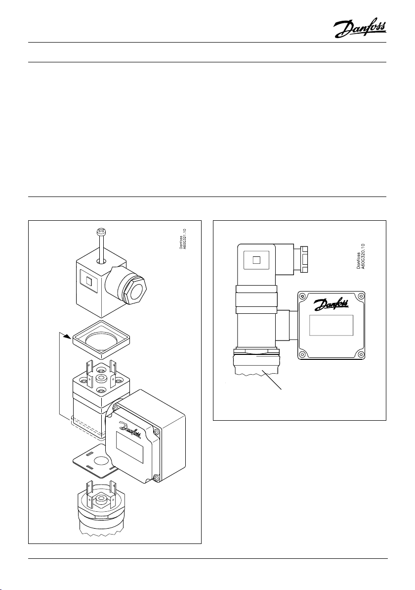
Electric connection
The MBD 1000 is simpy plugged into a transmitter by means of a special adaptor for the cubic
plug according to DIN43650.
Electric connection and commissioning of the
device must be carried out by trained and skilled
personnel.
Terminal assignment:
Use male plugs 1 and 2.
Supply voltage:
The display takes power directly from measuring
current.
Assembly
Wrong connection may lead to the destruction of
the display device. Danfoss cannot assume any
responsibility for this !!
Observe the maximum input current rating of
40mA under all circumstances !!
MBS/ AKS/ MBT
Transmitter connector
DIN 43650
2 IC.PI.P20.E2.02
© Danfoss A/S
Page 3

MBD 1000 Connection and operating instructions
Technical specication
Input signal 4 ... 20 mA (2-wire)
Max. allowed input current 40 mA
Reverse voltage protection polarized installation
Voltage drop across display approx. 3 V
Display 10 mm high LCD-display
Display range starting and end value freely selectable
Maximum display value 9999 digits
Minimum display value -1999 digits
Decimal point any position
Measuring accuracy 0.2% ± 1 digit
Temperature drift 100 ppm / °C
Measuring interval approx. 5 measurements / sec.
Filter 3 stages can be switched on
Nominal temperature 25°C
Amibent temperature 0 to 50°C
Relative atmospheric humidity 0 to 80% (non condensing)
Eletromagnetic compatibility:
Additional error:
Housing ABS. Front screen made of polycarbonate.
Connection specially designed adaptor for cubic plug
IP rating front side IP65
Fault codes
In case of unacceptable conditions in the system a fault code will be displayed.
Fault codes have been dened as follows:
In accordance with EN50081-1 and EN50082-2
< 1%
48.5 x 48.5 x 35.5 mm (L x W x D)
DIN43650 for simple connection.
Length of screw has to be adjusted.
FE 1: Measuring range has been exceeded
This fault code indicates that the measuring range of the A/D converter has been exceeded.
Potential fault cause: transmitter damaged
short-circuit in transmitter connection
MBD 1000 not/incorrectly congurated
Remedies: FE 1 will be reset as soon as the measuring values are back within
their permissible range. Please check your transmitter and transmitter
connecting cables.
FE 2: Measuring values have fallen below permissible range
This fault code indicates that the measuring values of the A/D converter have fallen below the
permissible range.
Potential fault cause: transmitter damaged
transmitter connection interrupted
MBD 1000 not/incorrectly congurated
Remedies: FE 2 will be reset as soon as the measuring values are back within
their permissible range. Please check your transmitter and transmitter
connecting cables.
© Danfoss A/S IC.PI.P20.E2.02 3
Page 4

MBD 1000 Connection and operating instructions
Conguration
Please note: measuring current should be
at least 4 mA during conguration!
1. Press button 1, "dP" (decimal point) will be
displayed.
Select decimal point position desired using
buttons 2 and 3.
Acknowledge decimal point position by
pressing button 1. "dP" will be displayed
again.
2. Press button 1 once again, "An 4" (display
for 4mA) will be displayed.
Use buttons 2 and 3 to set value to be
displayed on the MBD 1000 for an input
signal of 4mA.
Buttons 2 and 3 are equipped with a scrolling
function, i.e. the value will be increased
respectively decreased by 1 digit when
button 2 respectively button 3 is pressed
briey (no more than 1 s). When pressing
these buttons for a longer time (over 1 s)
the values will start „scrolling“ upwards
respectively downwards with the scrolling
speed being increased after approx. 6s.
Acknowledge value displayed by pressing
button 1. "An 4" will be displayed again.
3. Switch over to the next parameter by
pressing button 1 once again. "An20" will be
displayed (display for 20mA).
Use buttons 2 and 3 to set value to be
displayed on the MBD 1000 for an input
signal of 20mA.
Acknowledge value displayed by pressing
button 1. "An20" will be displayed again.
4. Press button 1 once again. "LI" (limit) will be
displayed.
Select measuring range limits desired using
buttons 2 and 3.
0 = Values exceeding/falling below limits are
acceptable. (FE1, FE2 displayed for
hardware limits)
1 = Values exceeding/falling below limits are
not acceptable. (FE1, FE2 displayed for
area limits)
Acknowledge selection made by pressing
button 1. "LI" will be displayed again. For
pressure and temperature measuring
transducers always enter "LI 0".
5. Press button 1 once again. "FILt" (lter) will
be displayed.
Select input lter 0, 1, 2 or 3 desired using
buttons 2 and 3.
0 = no lter
1 = lter 1 active
2 = lter 2 active
3 = lter 1 and lter 2 active
Filter 1: for ltering short pikes occurring when
relays and contactors are switched.
Make sure to always activate lter 1 if
high loads are switched in the vicinity
of the MBD 1000 (wires or sensor or if
large spikes are to be expected).
Additional display delay: approx. 0.5s
Filter 2: prevents ”jumping” of the last gure, a
phenomenon often found with digital
displays and controllers. Make sure to
always activate lter 2 if the display
range exceeds 2000 digits.
Additional display delay: approx. 1s
Acknowledge selection made by pressing button
1. "FILt" will be displayed again.
The adjustment of the MBD 1000 to the transmitter is now completed. The MBD 1000 can be
immediately switched over to display the current
measuring vlaue by pressing button 1.
IC.PI.P20.E2.02
© Danfoss A/S (DE-BD) 07-2007
 Loading...