

Page 1
i.
ii.
iii.
Service Kit Instructions
Series 42
Manual displacement control neutral start switch
The Neutral Start Switch (NSS) prevents the engine from
being started when the pump control handle is out of neutral.
The NSS should be wired in series with the engine starting
circuit. The switch contact is closed at the handle’s neutral
position and opens when the control handle is rotated 1.5°
to 2° from neutral.
The Backup Alarm Switch (BUA) outputs an electronic
signal when the control handle is in a reverse position. This
switch is normally wired in series with an audio output. The
switch contact is open until the control handle is rotated 2.6°
to 3.75° in the reverse direction.
WARNING:
The control handle’s neutral position must agree
with the pump’s neutral position for the NSS/BUA to
work effectively.
The Neutral Start/Backup Alarm Switch assembly can be
configured for three different setting.
i. A Neutral Start Switch only.
ii. A Neutral Start Switch with Backup Alarm for units
where clockwise (CW) handle rotation results in
“reverse” motion.
iii. A Neutral Start Switch with Backup Alarm for units
where counterclockwise (CCW) handle rotation
results in “reverse” motion
The setting must be in accordance with the configuration of
the unit. See the model code if uncertain of the type of NSS
you have.
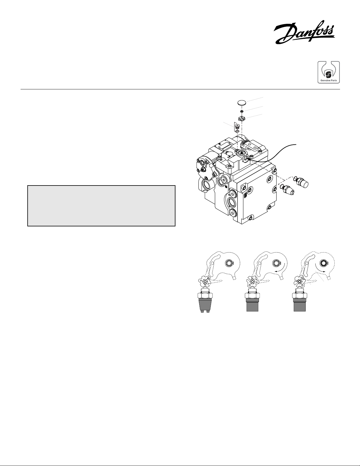
Alignment
Plug
NSS only
NSS Cover
NSS Control Nut
NSS Cam
NSS with Screw
Terminals
NSS Assembly on MDC
NSS with BUA
(CW = Reverse)
NSS Cavity
NSS with
Weatherpack
Control
Yolk
Cam
NSS with BUA
(CCW = Reverse)
Top View of NSS Showing Cam Positions
© Danfoss, 2013 BLN-10123 • Rev AA • September 2013 1
Page 2
Note:
Adjustment is normally required unless the function
of the NSS is changed (between i, ii, and iii).
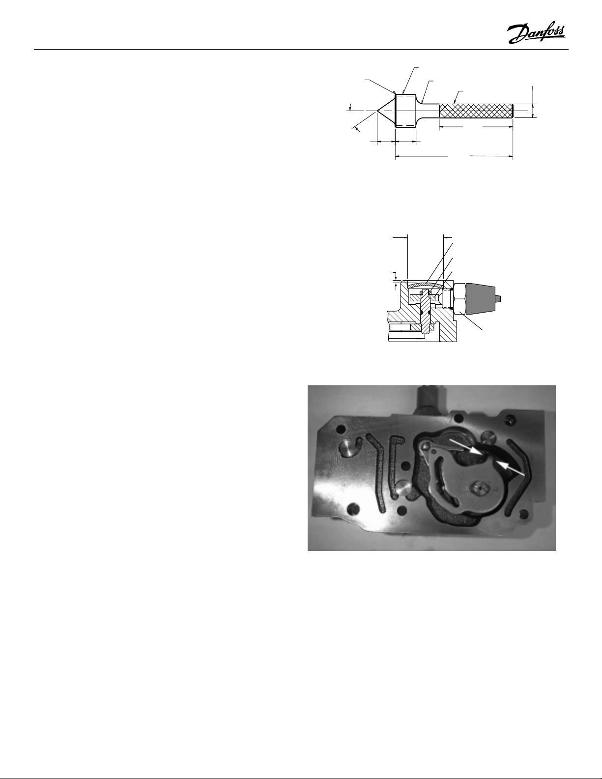
.04 x 45 Chamfer
9/16 -18UNF 2A THD
R.125
Knurl
ø .236
–.030
Adjustment of the NSS or NSS and BUA requires a special
alignment tool. Dimension are give at right.
Adjustment is performed by setting the cam positions within
the NSS assembly
1. The Manual Displacement Control (MDC) must be
removed from the housing.
2. Remove the NSS (
7
/8 inch hex).
3. Remove and discard the NSS cover by inserting a
screwdriver into the NSS cavity and popping off the
cover with a hammer. Be careful not to damage the
internal hardware.
4. Remove the control nut (8 mm hex).
5. Use a screwdriver to pop off the cam.
6. On the underside of the MDC, gently clamp a pair of
locking pliers around the spring contacts of the
control cam. Be careful not to dambe the spring
wires. The pliers should hold the nub on the control
cam to the pin underneath. This will hold the
control cam in neutral position.
7. Set cam in proper orientation according to the unit’s
configuration.
8. Screw special alignment tool in NSS cavity to hold
cam in place.
9. Place control nut on cam and torque to 4.1 to 6.8
Nm (3 - 5 ft•lbf).
10. Press new cover on top of cam cavity. This requires either an arbor
press or a full-sized punch.
The tool diameter should be 23.3 mm (0.916 in).
Press the new cover so that it sits 1.06 mm (0.0417
in) below the cast surface as illustrated at right.
11. Remove the alignment tool and locking pliers.
12. Place a new lubricated O-ring on NSS.
13. Reconnect the NSS to the MDC. Torque to 25 - 29
Nm (18 - 22 ft•lbf).
14. Reinstall MDC onto pump housing.
35.0
.306
.354
Material: .75 DIA x 3 ETD150
(All Dimensions in inches)
1.250
2.000
Alignment Tool
23.3 mm
(0.916 in.)
1.06 mm
(0.0417 in.)
NSS Cover
NSS Control Nut
NSS Cam
NSS
Side View of NSS and NSS Cavity
Underside of MDC Showing Clamping Position
of Locking Pliers
© Danfoss, 2013 BLN-10123 • Rev AA • September 2013 2
 Loading...