

Page 1
Service Kit Instructions
Series 20
Manifold replacement procedure
Manifold assembly kit
Quantity Description
1 Manifold assembly
2 O-rings
1 O-ring
6 Bolts
6 Washers
1 Orifice plug
A. Removal
1. Prior to removal of manifold assembly, remove all
dirt, and clean area where manifold assembly is attached
to end cap.
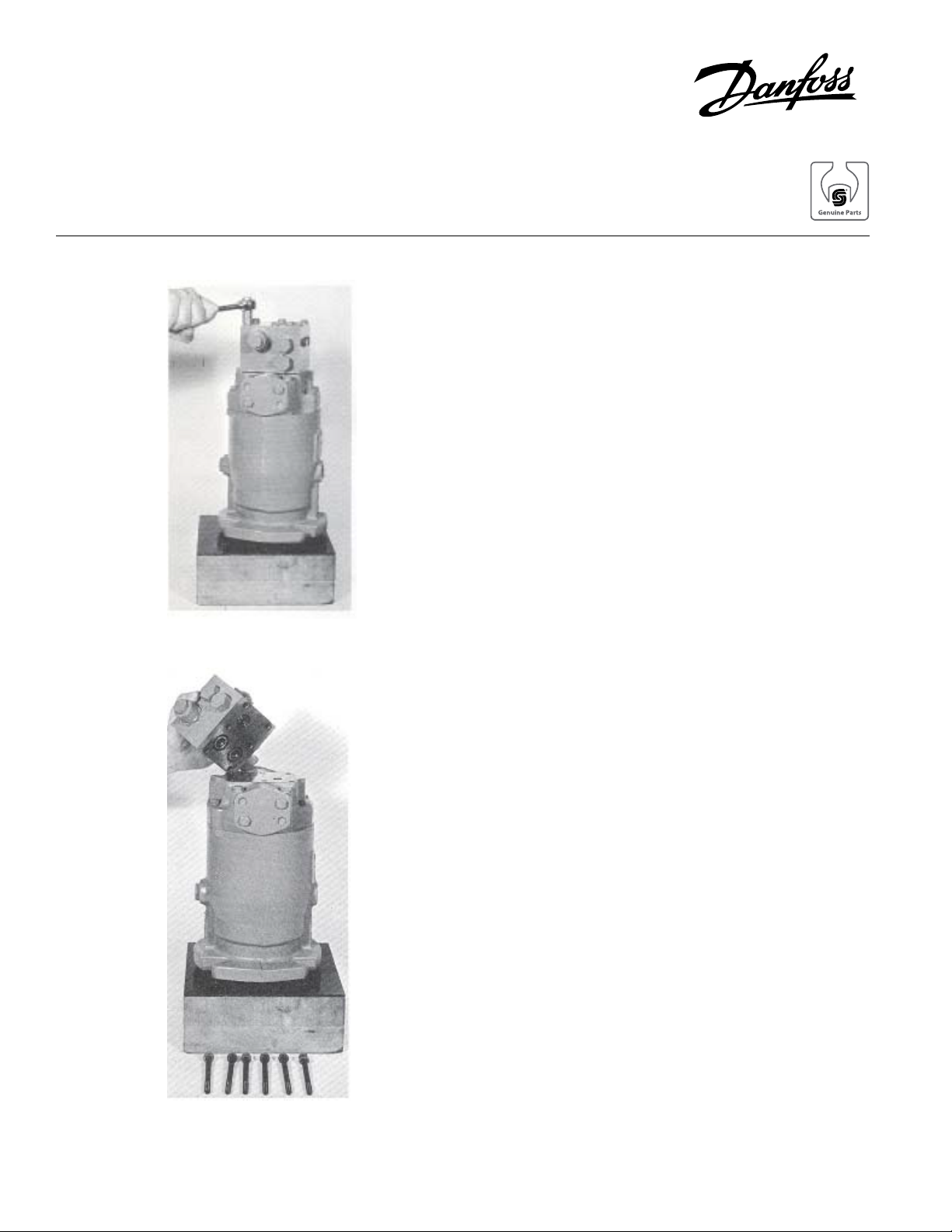
Figure N
2. Place drain pan under manifold to catch oil.
3. Remove the four (4) corner bolts holding manifold to
motor end cap. See figure N.
4. Grasp manifold to prevent it form dropping and
remove remaining two (2) mounting bolts. See figure P.
There is no gasket between the manifold and end cap.
Sealing is obtained by O-rings.
B. Installation
1. Use new O-rings.
2. The two grooves side by side require the larger Orings.
3. The remaining groove requires the orifice plug and
smaller O-ring.
4. Place manifold against motor end cap. Install new
bolts and washers being certain O-rings or orifice plug
did not slip from their grooves. Torque bolts 19-21 lbf ·ft.
5. Check reservoir oil.
Figure P
© Danfoss, 2013 BLN-9591 • Rev CA • September 2013 1
 Loading...