

Danfoss Maneurop reciprocating compressors MT, Maneurop reciprocating compressorsMTZ Application guide
Page 1
Application guidelines
Maneurop® reciprocating
compressors MT/MTZ
50 - 60 Hz
Group 2: R22, R417A, R407A/C/F, R134a, R404A / R507A, R448A / R449A, R452A, R513A
Group 1: R454C, R455A
www.danfoss.com
Page 2

Page 3

Application Guidelines
Content
General Information ........................................ 4
Maneurop® reciprocating compressors ......... 5
Code numbers (for ordering) ..........................................6
Compressor reference (indicated on the compressor
nameplate) .............................................................................6
Compressor model designation .....................................6
Specifications ................................................... 7
Technical specifications .....................................................7
Approvals and certificates ................................................7
Pressure equipment directive 2014/68/EU ................7
Low voltage directive 2014/35/EU ................................7
Machinery directive 2014/30/EU ................................... 7
Internal free volume ...........................................................7
Nominal performance data for R404A and R22 ......8
Nominal performance data for R407C and R134a ... 9
Nominal performance data for R407A and R407F .10
Nominal performance data R448A/R449A and
R452A .....................................................................................11
Nominal performance data R454C, R455A and
R513A .....................................................................................12
Operating envelopes ..................................... 13
Discharge temperature protection .............................16
Zeotropic refrigerant mixtures .....................................16
Phase shift ............................................................................17
Temperature glide .............................................................17
Dew temperature and Mean temperature for zeo-
tropic mixtures ...................................................................17
Outline drawings ........................................... 18
1 cylinder ..............................................................................18
2 cylinders ............................................................................19
4 cylinders ............................................................................20
Electrical connections and wiring ................ 21
Single phase electrical characteristics .......................21
Nominal capacitor values and relays ..........................21
Trickle circuit .......................................................................21
PSC wiring ............................................................................21
CSR wiring ............................................................................21
Suggested wiring diagrams ...........................................22
Three phase electrical characteristics ........................23
Winding resistance............................................................23
Motor protection and suggested wiring diagrams 23
Soft starters..........................................................................24
Voltage application range ..............................................24
IP rating .................................................................................24
Refrigerants and lubricants .......................... 25
General information .........................................................25
R22 ..........................................................................................25
Alternatives R22, HFC retrofit ........................................25
R407C .....................................................................................25
R134a .....................................................................................26
R404A .....................................................................................26
R507A .....................................................................................26
R407A .....................................................................................26
R407F .....................................................................................26
R448A/R449A ......................................................................26
R452A .....................................................................................27
R454C/R455A ......................................................................27
R513A .....................................................................................27
Hydrocarbons .....................................................................27
System design recommendations ................28
Piping design ......................................................................28
Operating limits .................................................................29
Operating voltage and cycle rate ................................30
Liquid refrigerant control and charge limit ..............30
Sound and vibration management .............. 32
Sound ....................................................................................32
Vibration ...............................................................................32
Installation and service ................................. 33
System cleanliness ............................................................33
Compressor handling, mounting and connection to
the system ............................................................................33
System pressure test ........................................................34
Leak detection ....................................................................34
Vacuum pull-down moisture removal .......................34
Start-up .................................................................................35
Ordering information and packaging ..........36
Packaging .............................................................................36
3AB196386425654en-021502
Page 4

Application Guidelines
General Information
Danfoss receiprocating compressors are
designed and manufactured with state of the
art technology and follow European and US
regulations. There is an added emphasis placed
on safety and reliability. Critical instructions are
highlighted with the following icons:
This icon indicates instructions to avoid
safety risk.
This icon indicates instructions to avoid
R
reliability risk.
The purpose of this guideline is informational,
with the intent to educate customers as to how
the compressors should properly function.
If you need any additional assistance, please
contact Danfoss Technichal Support. In any case,
Danfoss manufacturing accepts no liability as a
result of misuse or improper integration of the
compressor unit.
4 AB196386425654en-021502
Page 5
Application Guidelines
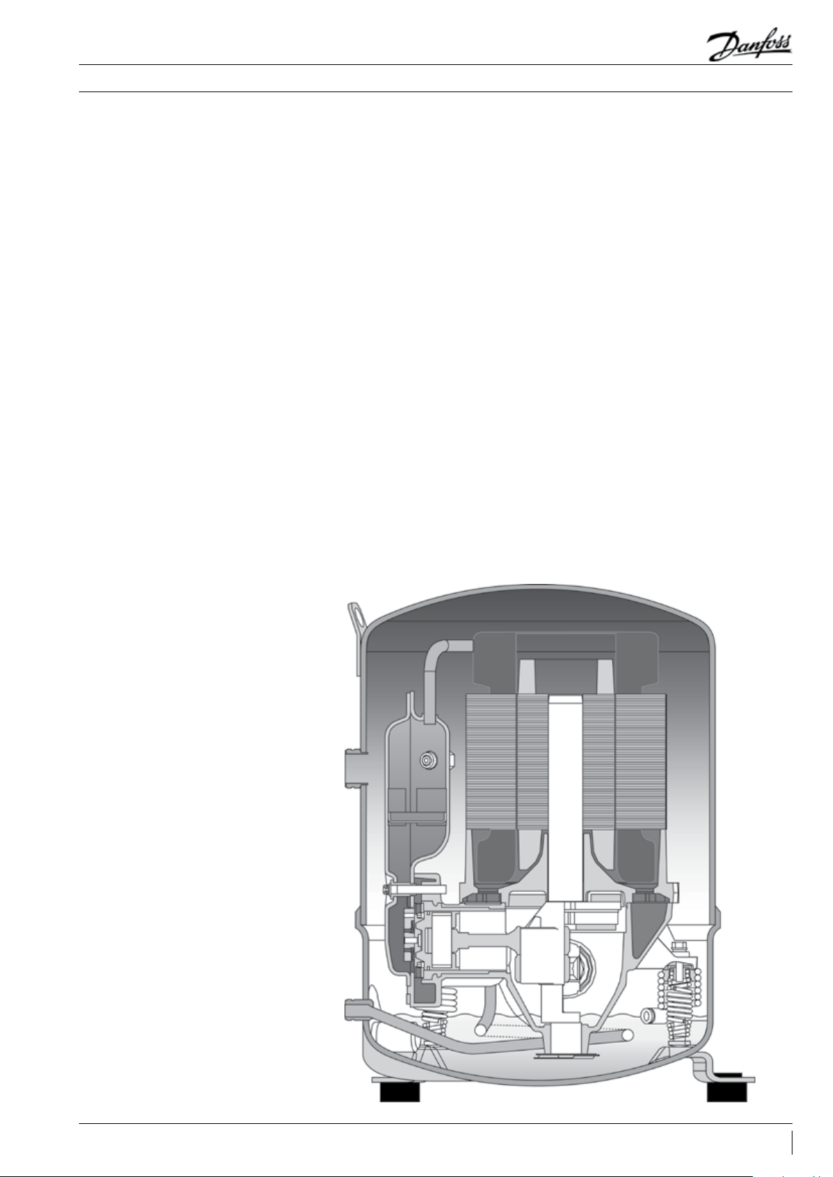
Maneurop® reciprocating compressors
Maneurop® reciprocating compressors from
Danfoss Commercial Compressors are specially
designed for applications with a wide range of
operating conditions. All components are of high
quality and precision in order to assure a long
product life.
Maneurop® MT and MTZ series compressors
are of the hermetic reciprocating type and are
designed for medium and high evaporating
temperature applications.
The positive benefits of internal motor
protection, high efficiency circular valve design
and high torque motors provide for a quality
installation.
MT & MTZ have the same mechanical and motor
design.
MT is charged with mineral oil while MTZ with
polyester oil.
These compressor ranges can be used with
a large choice of refrigerants according their
compatibility with the oil.
MT and MTZ compressors have a large internal
free volume that protects against the risk of
liquid hammering when liquid refrigerant enters
the compressor.
MT and MTZ compressors are fully suctiongas cooled. This means that no additional
compressor cooling is required and allows
the compressors to be insulated with acoustic
jackets, to obtain lower sound levels, without the
risk of compressor overheating.
MT and MTZ compressors are available in 16
different models with displacement ranging from
30 to 271 cm3/rev. Seven different motor voltage
ranges are available for single and three phase
power supplies at 50 and 60 Hz. All compressors
are available in VE version (oil equalisation + oil
sight glass).
5AB196386425654en-021502
Page 6
Application Guidelines
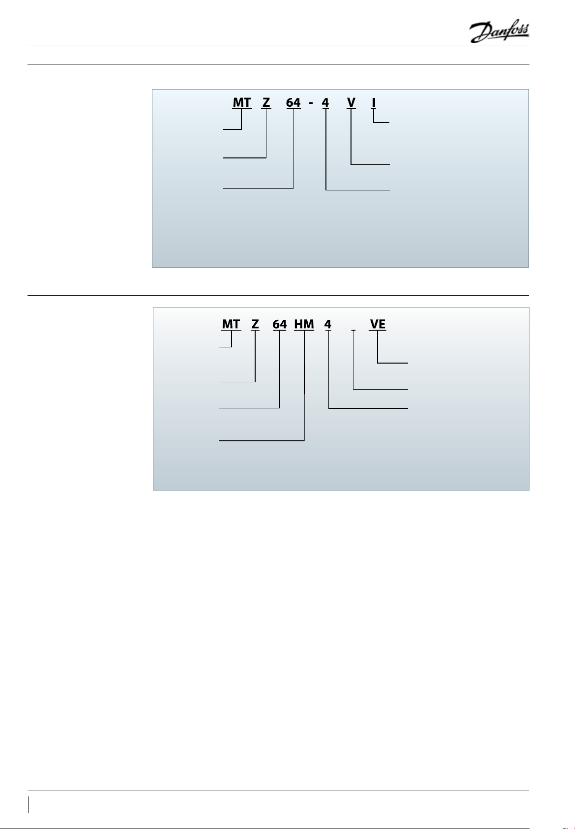
Code numbers (for ordering)
Compressor model designation
Compressor reference
(indicated on the compressor nameplate)
Compressor type
Polyolester oil
KBtu/h@ARI 60hz
Available code numbers are listed section “Ordering information and packaging”
D
Compressor
type
Polyolester oil
KBtu/h@ARI60hz
Displacement code
Packaging type
I : single pack
M : industrial pack
(see ordering section)
Oil equalisation port
and threaded sight glass
Motor voltage code*
1: 208-230V/1~/60Hz
3: 200-230V/3~/60Hz
4: 380-400 V/3~/50Hz & 460V/3~/60Hz
5: 220-240 V/1~/50Hz
6: 230 V/3~/50Hz
7: 500 V/3~/50Hz & 575V/3~/60Hz
9: 380 V/3~/60Hz
*Please consult Danfoss for motor version available
Oil equalisation port
and sight glass
Generation index
Motor voltage code*
1: 208-230V/1~/60Hz
3: 200-230V/3~/60 Hz
4: 380-400V/3~/50Hz & 460V/3~/60Hz
5: 220-240V/1~/50Hz
6: 230V/3~/50Hz
7: 500V/3~/50Hz & 575V/3~/60Hz
9: 380V/3~/60Hz
*Please consult Danfoss for motor version available
6 AB196386425654en-021502
Page 7
Application Guidelines
Specifications
Technical specifications
Compressor
model
MT/MTZ018 JA 30.23 5.26 1 0.95 21
MT/MTZ022 JC 3 8.12 6.63 1 0.95 21
MT/MTZ028 JE 48.06 8.36 1 0.95 23
MT/MTZ032 JF 53.86 9.37 1 0.95 24
MT/MTZ036 JG 60.47 10.52 1 0.95 24
MT/MTZ040 JH 67. 89 11. 81 1 0.95 24
MT/MTZ044 HJ 76.22 13. 26 2 1.8 35
MT/MTZ050 HK 85.64 14.90 2 1.8 35
MT/MTZ056 HL 96 .13 16.73 2 1.8 37
MT/MTZ064 HM 10 7.71 18.74 2 1. 8 37
MT/MTZ072 HN 120.94 21.0 4 2 1.8 40
MT/MTZ080 HP 135.78 23.63 2 1.8 40
MT/MTZ100 HS 171. 26 29.80 4 3.9 60
MT/MTZ125 HU 215.4 4 37.49 4 3.9 64
MT/MTZ144 HV 241.87 42.09 4 3.9 67
MT/MTZ160 HW 271.55 47. 25 4 3.9 67
Displacement
Code cm
3
/rev
m3/h at
2900 rpm
Cyl.
number
● Available in MT and MTZ ○ Available in MTZ only
Oil
charge
dm
3
Net
weight
kg
Available motor voltage codes
1 3 4 5 6 7 9
● ● ● ● -
● ● ● ● ●
● ● ● ● ●
- -
-
-
● ● ● ● ● ○ ●
● ● ● ● ● ○ ○
● ● ●
○ ● ●
● ● ●
● ● ●
● ● ●
● ●
-
● ●
-
● ●
-
● ●
-
● ●
-
● ●
-
●
-
○ ○ ●
-
● ○ ●
-
● ● ●
-
●
-
○
-
●
-
● ● ●
-
● ● ●
-
● ● ●
-
● ● ●
-
- -
-
-
-
●
○
●
●
●
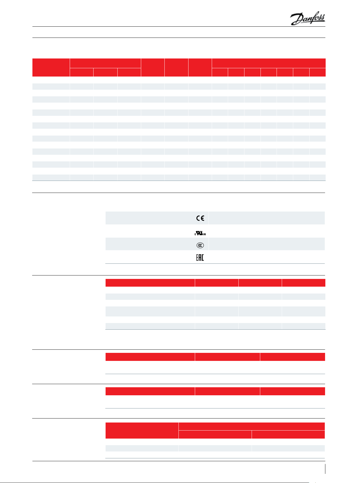
Approvals and certificates
Pressure equipment directive 2014/68/EU
Low voltage directive 2014/35/EU
Maneurop® MT/MTZ compressors comply with
the following approvals and certificates.
CE (European Directive)
UL
(Underwriters Laboratories)
CCC
(China Compulsory Product Certification)
EAC Eurasian conformity mark
Products MT/MTZ 018 to 040 MT/MTZ 018 to 040** MT/MTZ 044 to 160
Refrigerating fluids* Group 2 Group 1 Group 2
Category PED I II II
Evaluation module no scope D1 D1
Maximum/minimum allowable
temperature - TS
MT maximum allowable pressure - PS 18.4 bar(g) 18.4 bar(g) 18.4 bar(g)
MTZ maximum allowable pressure - PS 22.6 bar(g) 22.6 bar(g) 22.6 bar(g)
* According to the PED classification Group1 contains hazardous fluids e.g. flammable, while Group 2 all other fluids
** Only motor code 4 and 5
Products MT/MTZ 018 to 040 MT/MTZ 044 to 160
Manufacturer's declaration contact Danfoss contact Danfoss
50°C > Ts > -35°C 50°C > Ts > -35°C 50°C > Ts > -35°C
Other certificates/approvals please contact
Danfoss
All models
All 60 Hz models
All models code 4 and 5 under CCC scope.
All models voltage code 4 and 5
Machinery directive 2014/30/EU
Internal free volume
Products MT/MTZ 018 to 040 MT/MTZ 044 to 160
Manufacturer's declaration contact Danfoss contact Danfoss
Products
1 cyl. 7.76 0.28
2 cyl. 17.13 0.63
4 cyl. 32.2 1.20
Low side High side
Volume (litre)
7AB196386425654en-021502
Page 8
Application Guidelines
Specifications
Nominal performance data for R404A and R22
R404A Refrigeration
50 Hz, EN12900 ratings
Compressor
model
MTZ018-4* 1910 1.21 2.73 1.58 2070 1.31 2.86 5.39 2630 1.76 2.86 5.10
MTZ022-4* 2630 1.48 3.06 1.77 2830 1. 62 3.24 5.96 3600 2.05 3.27 5.99
MTZ028-4* 3430 1.96 4.04 1.75 3690 2.14 4.30 5.88 4680 2.68 4.23 5.96
MTZ032-4* 3980 2.16 4.25 1.84 4260 2.37 4.56 6.13 5110 2.98 4.56 5.85
MTZ036-4* 4670 2.58 4.95 1.81 4990 2.83 5.33 6.02 5900 3.33 5.09 6.05
MTZ040-4* 5330 2.95 5.87 1.81 5680 3. 24 6.29 5.98 6740 3.76 5.88 6.12
MTZ044-4* 5370 2.78 5.35 1.93 5780 3.02 5.67 6.53 7110 3.85 5.85 6.30
MTZ050-4* 6260 3.22 5.95 1.94 6700 3.50 6.33 6.53 8360 4.42 6.53 6.46
MTZ056-4* 6710 3.51 6.83 1.91 7250 3.85 7. 25 6.43 9490 4.98 7.52 6.50
MTZ064-4* 7980 4.20 7. 82 1.90 8590 4.60 8.35 6.37 10540 5.67 8.31 6.34
MTZ072-4* 8920 4.69 8.95 1.90 9570 5.11 9.50 6.39 11960 6.53 9.73 6.25
MTZ080-4* 10470 5.61 10. 20 1.87 1118 0 6.14 10.94 6.21 13610 7. 81 11. 35 5.95
MTZ100-4* 12280 6.76 12. 21 1.82 13170 7. 35 12 .94 6.12 154 80 8.72 12. 79 6.06
MT Z125 -4* 15710 8.44 14.69 1.86 16800 9.22 15.82 6.22 19970 11 .37 16.41 5.99
MTZ144 -4* 1849 0 9.78 16.77 1.89 19690 10.66 17.99 6.30 23540 12.9 9 18.47 6 .18
MTZ160-4* 20310 11. 08 18.80 1.83 21660 12.09 20.22 6 .11 25570 14.73 20.77 5.92
* 50 Hz, EN12900 data for indicated models are Asercom certified R404A data are also valid for refrigerant R507A
To = -10°C, Tc = 45°C, SC = 0K, SH = 10K
Cooling
capacity
W
Power
input
kW
Current
input
A
C .O.P.
W/W
To = -6.7°C, Tc = 48.9°C, SC = 0K, SH = 11.1K
Cooling
capacity
W
50 Hz, ARI ratings
Power
input
kW
Current
input
A
E.E.R.
Btu.h/W
To = -6.7°C, Tc = 48.9°C, SC = 0K, SH = 11.1K
Cooling
capacity
W
60 Hz, ARI ratings
Power
input
kW
Current
input
A
Btu.h/W
E.E.R.
R22 Refrigeration Air Conditioning
50 Hz, EN12900 ratings
Compressor
model
MT018-4 1690 1.0 0 2.27 1.69 3880 1.45 2.73 9.13 4660 1.74 2.73 9.14
MT022- 4 2490 1.29 2.55 1.94 5360 1.89 3.31 9.68 6440 2.27 3.31 9.68
MT028-4 3730 1.81 3.59 2.06 7380 2.55 4.56 9.88 8850 3.06 4.56 9.87
MT032- 4 3950 2 .11 3.73 1.87 8060 2.98 4.97 9.23 9680 3.58 4.97 9.23
MT036-4 4810 2.35 4.30 2.04 9270 3.37 5.77 9.39 11130 4.05 5.77 9.38
MT040-4 5220 2.67 4.86 1.95 10 480 3.86 6.47 9.27 12570 4.63 6.47 9.27
MT044-4 4860 2.46 5.02 1.9 8 10520 3.53 6.37 10.17 12890 4.32 6.42 10.18
MT050-4 5870 2.94 5.53 2.00 12230 4.19 7.20 9.96 14690 5.04 7. 26 9.95
MT056-4 6450 3.18 6.39 2.03 1375 0 4.58 8.19 10.25 16520 5.58 8.23 10.10
MT064-4 7750 3.64 7.03 2.13 1573 0 5. 27 9.16 10.19 18850 6.32 9.33 10.18
MT072-4 8710 4.19 8.48 2.08 18200 6 .12 10.98 10.15 2184 0 7. 33 10.77 10.17
MT080-4 10360 4.89 9.52 2 .12 20740 7.08 12. 48 10.00 24890 8.50 12 .34 9.99
MT10 0-4 113 30 5.79 11.82 1.96 23400 7. 98 14. 59 10.01 28080 9.58 14. 59 10.0 0
MT 125-4 15260 7. 55 12 .28 2.02 30430 10.66 17. 37 9.74 36520 12. 80 17. 37 9.74
MT144-4 17280 8.47 17. 06 2.04 34340 11.9 6 22.75 9.80 41210 14. 35 22.75 9.80
MT16 0-4 19190 9.49 16. 81 2.02 38270 13. 40 2 2.16 9.75 45930 16. 08 22.16 9.75
To: Evaporating temperature at dew point (saturated suction temperature)
Tc: Condensing temperature at dew point (saturated discharge temperature)
SC: Subcooling
SH: Superheat
ARI capacity and power input data are +/- 5%
Asercom: Association of European Refrigeration Compressor and Controls Manufacturers
ARI: Air Conditioning and Refrigeration Institute
To = -10°C, Tc = 45°C, SC = 0K, SH = 10K
Cooling
capacity
W
Power
input
kW
Current
input
A
C .O.P.
W/W
To = 7.2°C, Tc = 54.4°C, SC = 8.3K, SH = 11.1K
Cooling
capacity
W
50 Hz, ARI ratings
Power
input
kW
Current
input
A
E.E.R.
Btu.h/W
To = 7.2°C, Tc = 54.4°C, SC = 8.3K, SH = 11.1K
Cooling
capacity
W
60 Hz, ARI ratings
Power
input
kW
Current
input
A
E.E.R.
Btu.h/W
8 AB196386425654en-021502
Page 9
Application Guidelines
Specifications
Nominal performance data for R407C and R134a
R407C Air Conditioning
50 Hz, EN12900 ratings
Compressor
model
MTZ018-4* 3470 1.27 2.73 2.73 3850 1.38 2.86 9. 52 5050 1.73 2.82 9.96
MTZ022-4* 4550 1.71 3.27 2.67 5020 1.86 3.47 9.21 6280 2.26 3.45 9.48
MTZ028-4* 5890 2.17 4.30 2.72 6540 2.36 4.57 9.46 8220 2.82 4. 41 9.95
MTZ032-4* 6650 2.43 4.57 2.74 7330 2.66 4.90 9.40 9000 3.20 4.80 9.60
MTZ036-4* 7510 2.93 5.58 2.56 8280 3.21 5.99 8.80 9990 3.90 5.78 8. 74
MTZ040-4* 8660 3.40 6.46 2.55 9580 3.71 6.92 8.81 117 20 4.46 6.69 8.97
MTZ044-4* 9130 3.12 5.84 2.93 10100 3.38 6.18 10.20 127 30 4.25 6.34 10.22
MTZ050-4* 10420 3.69 6 .51 2.83 11530 4.01 6.95 9.81 14110 4.87 7. 06 9.89
MTZ056-4* 1168 0 4.02 7. 45 2.90 13000 4.37 7.91 10.15 16050 5.40 8.03 10.14
MTZ064-4* 13360 4.61 8.35 2.90 14850 5.02 8.91 10.10 18090 6.14 9.01 10.06
MTZ072-4* 15320 5.42 9.85 2.83 170 50 5.87 10.48 9.91 20780 7. 30 10. 61 9.72
MTZ080-4* 17380 6.29 11.31 2.76 19330 6.83 12 .08 9.66 22870 8.24 11. 99 9.47
MTZ100-4* 20480 7. 38 13 .05 2.78 22700 8.00 13 .83 9.68 28230 9.86 14. 22 9.77
MT Z125 -4* 26880 9.48 16 .12 2.84 29780 10.33 17. 33 9.84 35620 12.83 19.24 9.48
MTZ144 -4* 29770 10.68 18.07 2.79 33060 11.59 19.35 9.74 40900 14.42 20.40 9.68
MTZ160-4* 34090 12 .41 20.68 2.75 37820 13.46 22.14 9.59 45220 16. 64 23 .13 9. 27
* 50 Hz, EN12900 data for indicated models are Asercom certified
To = 5°C, Tc = 50°C, SC = 0K, SH = 10K
Cooling
capacity
W
Power
input
kW
Current
input
A
C .O.P.
W/W
To = 7.2°C, Tc = 54.4°C, SC = 8.3K, SH = 11.1K
Cooling
capacity
W
50 Hz, ARI ratings
Power
input
kW
Current
input
A
E.E.R.
Btu.h/W
To = 7.2°C, Tc = 54.4°C, SC = 8.3K, SH = 11.1K
Cooling
capacity
W
60 Hz, ARI ratings
Power
input
kW
Current
input
A
Btu.h/W
E.E.R.
R134a Refrigeration Air Conditioning
50 Hz, EN12900 ratings
Compressor
model
MTZ018- 4 1075 0.69 1.92 1. 56 2532 0.99 2.19 8.74 3038 1.19 2.29 8.74
MTZ022-4 14 08 0.82 2.16 1.73 3335 1.20 2.51 9.52 4001 1.4 4 2.62 9.52
MTZ028-4 1823 1.02 2.83 1.79 4217 1.53 3.30 9.39 5061 1.84 3.44 9.39
MTZ032-4 2076 1.25 3.33 1.66 4907 1.87 3.94 8.94 5889 2.25 4 .11 8.94
MTZ036-4 2753 1.45 3.32 1.9 0 6013 2.13 4.09 9.62 7216 2.56 4.26 9.62
MTZ040-4 2914 1.61 3.81 1.81 6342 2.33 4.89 9.28 7610 2.80 5.10 9.28
MTZ044-4 2926 1.49 4.05 1.96 6836 2.22 4.73 10. 51 8203 2.66 4.93 10.51
MTZ050-4 3364 1. 80 4.32 1. 87 7956 2.63 5.20 10.31 9547 3.16 5.42 10. 31
MTZ056-4 3526 1.88 5.31 1.87 8621 2.85 6 .17 10.34 10346 3. 41 6.44 10.34
MTZ064-4 4192 2.17 5.71 1.9 4 10 057 3.26 6. 81 10.51 12069 3.92 7.10 10.51
MTZ072-4 4873 2.50 6.67 1.95 11543 3.78 7.99 10. 41 13852 4.54 8.33 10.41
MTZ080-4 5857 2.93 7.22 2.00 1326 2 4.35 8.83 10.41 15915 5.23 9.21 10 .41
MTZ100-4 6617 3.65 8.67 1.82 15452 5.28 10.24 10.00 185 42 6.34 10.68 10.00
MT Z125 -4 8306 4.17 8.89 1.99 18941 6.29 11.5 0 10.27 22729 7. 55 11.99 10.27
MTZ144 -4 10732 5.40 11. 35 1.99 23536 7. 83 14.19 10. 27 28243 9. 39 14.80 10.27
MTZ160-4 1190 0 5.84 11.71 2.04 25779 8.57 15.11 10. 27 30935 10.29 15. 76 10.27
To: Evaporating temperature at dew point (saturated suction temperature)
Tc: Condensing temperature at dew point (saturated discharge temperature)
SC: Subcooling
SH: Superheat
ARI capacity and power input data are +/- 5%
Asercom: Association of European Refrigeration Compressor and Controls Manufacturers
ARI: Air Conditioning and Refrigeration Institute
To = -10°C, Tc = 45°C, SC = 0K , SH = 10K
Cooling
capacity
W
Power
input
kW
Current
input
A
C .O.P.
To = 7.2°C, Tc = 54.4°C, SC = 8.3K, SH = 11.1K
Cooling
W/W
capacity
W
50 Hz, ARI ratings
Power
input
kW
Current
input
A
E.E.R.
Btu.h/W
To = 7.2°C, Tc = 54.4°C, SC = 8.3K, SH = 11.1K
Cooling
capacity
W
60 Hz, ARI ratings
Power
input
kW
Current
input
A
E.E.R.
Btu.h/W
9AB196386425654en-021502
Page 10

Application Guidelines
Specifications
Nominal performance data for R407A and R407F
R4 07A Refrigeration
50 Hz, EN12900 ratings
Compressor
model
MTZ018- 4 1740 1.02 2.46 1.70 1940 1.12 2.58 5.91 2330 1.35 2.69 5.89
MTZ022-4 2390 1.26 2.75 1.90 2650 1.39 2.91 6.51 3180 1.67 3.04 6.50
MTZ028-4 3130 1.67 3.63 1.88 3470 1.85 3.87 6.40 416 0 2.22 4.04 6.40
MTZ032-4 3640 1.84 3.82 1.98 4000 2.04 4.10 6.69 4800 2.53 4.28 6.48
MTZ036-4 4260 2.19 4.45 1.95 4670 2.43 4.80 6.56 5600 2.92 5.00 6.55
MTZ040-4 4890 2.51 5.28 1.94 5340 2.80 5.67 6.51 6 410 3.36 5.91 6.51
MTZ044-4 4890 2.36 4.81 2.08 5 410 2.60 5.11 7.1 0 6500 3.12 5.33 7.11
MTZ050-4 5700 2.73 5.35 2.09 6280 3.01 5.69 7.12 7530 3.61 5.94 7.12
MTZ056-4 6120 2.98 6 .14 2.05 6790 3.30 6.53 7.0 2 8140 3.96 6.81 7.0 2
MTZ064-4 7270 3.57 7. 04 2.04 8040 3.95 7. 51 6.95 9650 4.75 7. 83 6.93
MTZ072-4 8130 3.98 8.05 2.04 8960 4.40 8.55 6.95 10760 5.28 8.92 6.96
MTZ080-4 9540 4.76 9.17 2.00 10 470 5.28 9.85 6.77 125 70 6.33 10. 27 6.78
MTZ100-4 1120 0 5. 74 10.98 1.95 12320 6.32 11.65 6.65 14790 7.58 12.15 6.66
MT Z125 -4 14330 7.17 13.21 2.00 15740 7.9 3 14. 24 6.77 18890 9. 51 14. 86 6.78
MTZ144 -4 16870 8.32 15.08 2.03 184 60 9.18 16 .19 6.86 22150 11. 02 16. 89 6.86
MTZ160-4 18520 9.42 16 .91 1.97 20300 10.43 18.20 6.64 24360 12.51 18.99 6.65
To: Evaporating temperature at dew point (saturated suction temperature)
Tc: Condensing temperature at dew point (saturated discharge temperature)
SC: Subcooling
SH: Superheat
To = -10°C, Tc = 45°C, SC = 0K, SH = 10K
Cooling
capacity
W
Power
input
kW
Current
input
A
C .O.P.
W/W
To = -6.7°C, Tc = 48.9°C, SC = 0K, SH = 11.1K
Cooling
capacity
W
50 Hz, ARI ratings
Power
input
kW
Current
input
A
E.E.R.
Btu.h/W
To = -6.7°C, Tc = 48.9°C, SC = 0K, SH = 11.1K
Cooling
capacity
W
60 Hz, ARI ratings
Power
input
kW
Current
input
A
Btu.h/W
E.E.R.
R407F Refrigeration
50 Hz, EN12900 ratings
Compressor
model
MTZ018- 4 1850 1.08 2.53 1.71 2080 1.19 2.66 5.97 2500 1.43 2.77 5.97
MTZ022-4 2540 1.33 2.83 1.91 2840 1.48 3.01 6.55 3410 1.77 3.14 6.58
MTZ028-4 3320 1.76 3.74 1.89 3710 1.96 4.00 6.46 4450 2.35 4.17 6.46
MTZ032-4 3860 1.94 3.93 1.99 4280 2.16 4.24 6.76 5130 2.59 4.42 6.76
MTZ036-4 4520 2.32 4.58 1.95 5010 2.58 4.95 6.63 6010 3.10 5 .17 6.62
MTZ040-4 517 0 2.65 5.43 1.95 5700 2.96 5.85 6.57 6840 3.55 6.10 6.58
MTZ044-4 5200 2.49 4.95 2.09 5810 2.76 5.28 7.18 6970 3.31 5.50 7.19
MTZ050-4 6060 2.90 5.50 2.09 6730 3.20 5.88 7.18 8080 3.85 6 .13 7.16
MTZ056-4 6500 3.16 6.31 2.06 7270 3. 51 6.74 7. 07 8730 4.21 7.0 3 7. 08
MTZ064-4 7730 3.78 7.23 2.05 8620 4.19 7. 76 7.0 2 10340 5.03 8.09 7. 02
MTZ072-4 8640 4.21 8.27 2.05 9 610 4.66 8.84 7. 04 115 30 5.60 9.22 7. 03
MTZ080-4 10140 5.04 9.43 2.01 11230 5.60 10.18 6.84 13470 6.72 10.61 6.84
MTZ100-4 1190 0 6.07 11. 28 1.96 13220 6.71 12.04 6.72 15870 8.05 12 .55 6.73
MT Z125 -4 15220 7. 58 13. 58 2.01 16870 8. 41 14.72 6.85 20240 10.09 15. 35 6.85
MTZ144 -4 17910 8.78 15. 50 2.04 197 70 9.72 16.73 6.94 23730 11.6 6 17.45 6.95
MTZ160-4 19 670 9.95 17.38 1.98 2174 0 11.03 18 .81 6.73 26090 13. 24 19. 62 6.73
To: Evaporating temperature at dew point (saturated suction temperature)
Tc: Condensing temperature at dew point (saturated discharge temperature)
SC: Subcooling
SH: Superheat
To = -10°C, Tc = 45°C, SC = 0K, SH = 10K
Cooling
capacity
W
Power
input
kW
Current
input
A
C .O.P.
W/W
To = -6.7°C, Tc = 48.9°C, SC = 0K, SH = 11.1K
Cooling
capacity
W
50 Hz, ARI ratings
Power
input
kW
Current
input
A
E.E.R.
Btu.h/W
To = -6.7°C, Tc = 48.9°C, SC = 0K, SH = 11.1K
Cooling
capacity
W
60 Hz, ARI ratings
Power
input
kW
Current
input
A
E.E.R.
Btu.h/W
Asercom: Association of European Refrigeration Compressor and Controls Manufacturers
ARI: Air Conditioning and Refrigeration Institute
10 AB196386425654en-021502
Page 11

Application Guidelines
Specifications
Nominal performance data R448A/R449A and R452A
R448A/R449A Refrigeration
50 Hz, EN12900 ratings
Compressor
model
MTZ018- 4 1840 1.04 2.55 1.77 2030 1.14 2.66 6.08 2430 1.36 2.78 6.10
MTZ022-4 2580 1.37 2.86 1. 88 2820 1.52 3.03 6.33 3380 1.82 3.16 6.34
MTZ028-4 3180 1.69 3.85 1. 89 3480 1.87 4.07 6.35 4170 2.24 4.25 6.35
MTZ032-4 3660 1.87 3.68 1.9 6 3970 2.08 3.97 6 .51 4770 2.49 4.14 6.54
MTZ036-4 4250 2.24 4.65 1.90 4650 2.48 4.97 6.40 5580 2.98 5 .18 6.39
MTZ040-4 4880 2.62 5.87 1.86 5340 2.90 6.27 6.28 6 410 3.48 6.54 6.29
MTZ044-4 5010 2.49 4.94 2.01 5500 2.74 5.25 6.85 6600 3.28 5.48 6.87
MTZ050-4 5700 2.87 5. 41 1.98 6310 3.18 5.74 6.77 7570 3.82 5.99 6.76
MTZ056-4 6340 3.16 6.53 2.00 7010 3.50 6.93 6.84 8 410 4.20 7.23 6.83
MTZ064-4 7330 3.62 7. 05 2.02 8040 4.01 7.56 6.84 9650 4.81 7.89 6.85
MTZ072-4 8440 4.20 8.80 2.01 9260 4.64 9.44 6.81 11110 5.57 9.85 6. 81
MTZ080-4 10010 4.97 9.66 2.02 10930 5.48 10. 34 6. 81 13120 6.57 10.79 6.82
MTZ100-4 1131 0 5.79 10.99 1.95 12430 6.37 11. 66 6.66 14910 7.65 12.17 6.65
MT Z125 -4 15220 7.4 5 13. 24 2.04 16720 8 .19 14.06 6.97 20060 9.88 14.67 6.93
MTZ144 -4 17560 8.63 15 .45 2.03 19040 9. 50 16 .69 6.84 22850 11. 40 17. 40 6.84
MTZ160-4 20140 9.87 17.11 2.04 21830 10.87 18.48 6.85 26200 13.04 19.27 6.86
To: Evaporating temperature at dew point (saturated suction temperature)
Tc: Condensing temperature at dew point (saturated discharge temperature)
SC: Subcooling
SH: Superheat
To = -10°C, Tc = 45°C, SC = 0K, SH = 10K
Cooling
capacity
W
Power
input
kW
Current
input
A
C .O.P.
W/W
To = -6.7°C, Tc = 48.9°C, SC = 0K, SH = 11.1K
Cooling
capacity
W
50 Hz, ARI ratings
Power
input
kW
Current
input
A
E.E.R.
Btu.h/W
To = -6.7°C, Tc = 48.9°C, SC = 0K, SH = 11.1K
Cooling
capacity
W
60 Hz, ARI ratings
Power
input
kW
Current
input
A
Btu.h/W
E.E.R.
R452A Refrigeration
50 Hz, EN12900 ratings
Compressor
model
MTZ018- 4 2000 1.15 2.65 1.74 2150 1.25 2.77 5.87 2580 1.49 2.88 5.91
MTZ022-4 2810 1.51 2.98 1.86 3010 1.65 3.15 6.23 3610 1.98 3.29 6.22
MTZ028-4 3250 1.86 4.00 1.75 3480 2.03 4.23 5.85 4170 2.44 4.41 5.83
MTZ032-4 3790 2.06 3.83 1.84 4060 2.27 4 .13 6.10 4870 2.73 4 .31 6.09
MTZ036-4 4300 2.48 4.84 1.74 4610 2.72 5.17 5.78 5530 3.26 5.39 5.79
MTZ040-4 5090 2.89 6 .11 1.76 5470 3 .18 6.52 5.87 6560 3.81 6.80 5.88
MTZ044-4 5370 2.73 5.24 1.96 5780 2.98 5.55 6.62 6940 3.58 5.79 6.62
MTZ050-4 6110 3.16 5.74 1.93 6630 3.47 6.07 6.52 7960 4 .16 6.33 6.53
MTZ056-4 6790 3.48 6.93 1.95 7370 3.82 7.33 6.58 8850 4.58 7. 64 6.59
MTZ064-4 7840 3.98 7.48 1.97 8450 4.36 8.00 6.61 10140 5.24 8.34 6.60
MTZ072-4 9020 4. 61 9.34 1.9 6 9730 5.06 9.98 6.56 11670 6.07 10.41 6.56
MTZ080-4 9680 5.26 10. 04 1.84 10390 5.75 10.72 6.17 12470 6.90 11.18 6.17
MTZ100-4 12310 6.37 11. 68 1.93 13270 6.97 12.42 6.50 15930 8. 37 12 .96 6.50
MT Z125 -4 16 070 8.19 14.09 1.96 17330 8.96 14.98 6.60 20790 10.75 15. 62 6.60
MTZ144 -4 17830 9.58 16.44 1.86 18950 10.4 6 17.77 6.18 22740 12 .55 18 .54 6.18
MTZ160-4 19880 10.80 18.20 1.84 21130 11.8 0 19. 68 6 .11 25360 14.16 20.52 6 .11
To: Evaporating temperature at dew point (saturated suction temperature)
Tc: Condensing temperature at dew point (saturated discharge temperature)
SC: Subcooling
SH: Superheat
To = -10°C, Tc = 45°C, SC = 0K, SH = 10K
Cooling
capacity
W
Power
input
kW
Current
input
A
C .O.P.
W/W
To = -6.7°C, Tc = 48.9°C, SC = 0K, SH = 11.1K
Cooling
capacity
W
50 Hz, ARI ratings
Power
input
kW
Current
input
A
E.E.R.
Btu.h/W
To = -6.7°C, Tc = 48.9°C, SC = 0K, SH = 11.1K
Cooling
capacity
W
60 Hz, ARI ratings
Power
input
kW
Current
input
A
Btu.h/W
E.E.R.
11AB196386425654en-021502
Page 12
Application Guidelines
Specifications
Nominal performance data R454C, R455A and R513A
R454C Refrigeration
50 Hz, EN12900 ratings
Compressor
model
To = -10°C, Tc = 45°C , SC = 0K , SH = 10K 50 Hz
Cooling
capacity
W
Power
input
kW
Current
input
A
C .O.P.
W/W
To = -6.7°C, Tc = 48.9°C, SC = 0K, SH = 11.1K
Cooling
capacity
W
MTZ018- 4 15 69 0.87 2.28 1.8 1734 0.96 2.36 6.19 211 0 1.16 2.24 6.22
MTZ022-4 2108 1.16 2.39 1.82 2309 1. 28 2.53 6.16 2909 1.64 2.64 6.06
MTZ028-4 2768 1.49 3.75 1.85 3646 1.84 3.61 6.77 3992 2.09 3.81 6.52
MTZ032-4 3317 1.67 3. 37 1.99 3021 1.63 3.93 6.32 4763 2.29 3.61 7.11
MTZ036-4 3722 1.97 4.43 1.89 4132 2.17 4.69 6.49 5325 2.73 4.63 6.64
MTZ040-4 4479 2.33 5.3 1.92 4918 2.59 5.64 6.49 6072 3.1 5.41 6.67
To: Evaporating temperature at dew point (saturated suction temperature)
Tc: Condensing temperature at dew point (saturated discharge temperature)
SC: Subcooling
SH: Superheat
R455A Refrigeration
Compressor
model
To = -10°C, Tc = 45°C , SC = 0K , SH = 10K 50 Hz
Cooling
capacity
MTZ018- 4 17 08 1.0 2.5 1.71 18 82 1.09 2.56 5.87 2276 1.3 2.42 5.99
MTZ022-4 2424 1.27 2.53 1.91 2654 1.4 2.68 6.46 3394 1.76 2.78 6.58
MTZ028-4 3115 1. 6 3.77 1.95 3405 1.74 3.95 6.66 4416 2.22 3.87 6.79
MTZ032-4 3534 1.76 3.52 2.01 3849 1.92 3.72 6.85 5081 2.46 3.84 7.0 4
MTZ036-4 4002 2.08 4.57 1.93 4441 2.3 4.85 6.59 5661 2.87 4.78 6.73
MTZ040-4 4668 2.43 5.54 1.92 5110 2.69 5.87 6.49 6524 3.28 5.8 6.78
To: Evaporating temperature at dew point (saturated suction temperature)
Tc: Condensing temperature at dew point (saturated discharge temperature)
SC: Subcooling
SH: Superheat
50 Hz, EN12900 ratings
Power
input
W
kW
Current
input
A
C .O.P.
W/W
To = -6.7°C, Tc = 48.9°C, SC = 0K, SH = 11.1K
Cooling
capacity
W
50 Hz, ARI ratings
Power
input
kW
Current
input
A
50 Hz, ARI ratings
Power
input
kW
Current
input
A
E.E.R.
Btu.h/W
E.E.R.
Btu.h/W
To = -6.7°C, Tc = 48.9°C, SC = 0K, SH = 11.1K
60 Hz, ARI ratings
Cooling
capacity
W
Power
input
kW
Current
input
A
Btu.h/W
60 Hz, ARI ratings
To = -6.7°C, Tc = 48.9°C, SC = 0K, SH = 11.1K
Cooling
capacity
W
Power
input
kW
Current
input
A
Btu.h/W
E.E.R.
E.E.R.
R513A Refrigeration Air Conditioning
50 Hz, EN12900 ratings
Compressor
model
To = -10°C, Tc = 45°C , SC = 0K , SH = 10K
Cooling
capacity
W
Power
input
kW
Current
input
A
To = 7.2°C, Tc = 54.4°C , SC = 8.3K , SH = 11.1K
C .O.P.
W/W
Cooling
capacity
W
MTZ018- 4 118 1 0.74 2.37 1.60 2757 1.03 2.63 9.15 3395 1. 23 2.40 9.45
MTZ022-4 154 6 0.88 2.13 1.76 3526 1.26 2.53 9.56 4425 1.58 2.57 9.56
MTZ028-4 1949 1.14 3.32 1.71 4426 1.6 4 3.77 9. 22 5608 2.02 3.59 9.49
MTZ032-4 2318 1.27 2.90 1. 83 5107 1.84 3.60 9.45 6543 2.30 3.60 9.73
MTZ036-4 2670 1.47 3.70 1.81 6 010 2.12 4.59 9.66 7145 2.59 4. 51 9.42
MTZ040-4 3169 1.78 4 .74 1.78 6888 2.53 5.62 9.28 8288 2.99 5.28 9.45
MTZ044-4 3183 1.68 4.13 1.89 7380 2.40 4.84 10. 51 8 915 2.94 4.82 10.38
MTZ050-4 3621 1.90 4.30 1.91 8085 2.73 5.27 10.10 9735 3.42 5.62 9.73
MTZ056-4 3822 2.05 5.27 1.87 8894 2.97 6.28 10.20 11241 3.80 6.19 10.10
MTZ064-4 4419 2.34 5.70 1.89 10141 3.44 6.91 10.07 12580 4.34 6.91 9.90
MTZ072-4 5037 2.70 7. 05 1.87 114 36 3.95 8.35 9.90 14 046 4.97 8 .12 9.66
MTZ080-4 5700 3.09 7. 27 1. 85 12963 4.54 8.86 9.73 16031 5.76 9.02 9.52
MTZ100-4 7150 3.91 8.96 1.83 15950 5.53 10.65 9.86 19397 6.72 10.54 9.86
MT Z125 -4 9614 4.81 9.73 2.00 21058 7. 00 12 .58 10.27 25367 8.69 13 .03 9.97
MTZ144 -4 10999 5.60 11.70 1.96 23855 8.10 14.64 10.07 28791 9.98 15. 04 9.86
MTZ160-4 12490 6.38 12.63 1.96 26 641 9.26 16.28 9.83 31756 11. 57 16.80 9.39
To: Evaporating temperature at dew point (saturated suction temperature)
Tc: Condensing temperature at dew point (saturated discharge temperature)
SC: Subcooling
SH: Superheat
ARI capacity and power input data are +/- 5%
Asercom: Association of European Refrigeration Compressor and Controls Manufacturers
ARI: Air Conditioning and Refrigeration Institute
50 Hz, ARI ratings
Power
input
kW
Current
input
A
E.E.R.
Btu.h/W
To = 7.2 °C, Tc = 54.4°C , SC = 8.3K , SH = 11.1K
60 Hz, ARI ratings
Cooling
capacity
W
Power
input
kW
Current
input
A
E.E.R.
Btu.h/W
12 AB196386425654en-021502
Page 13
Application Guidelines
MT - R22 - R417A
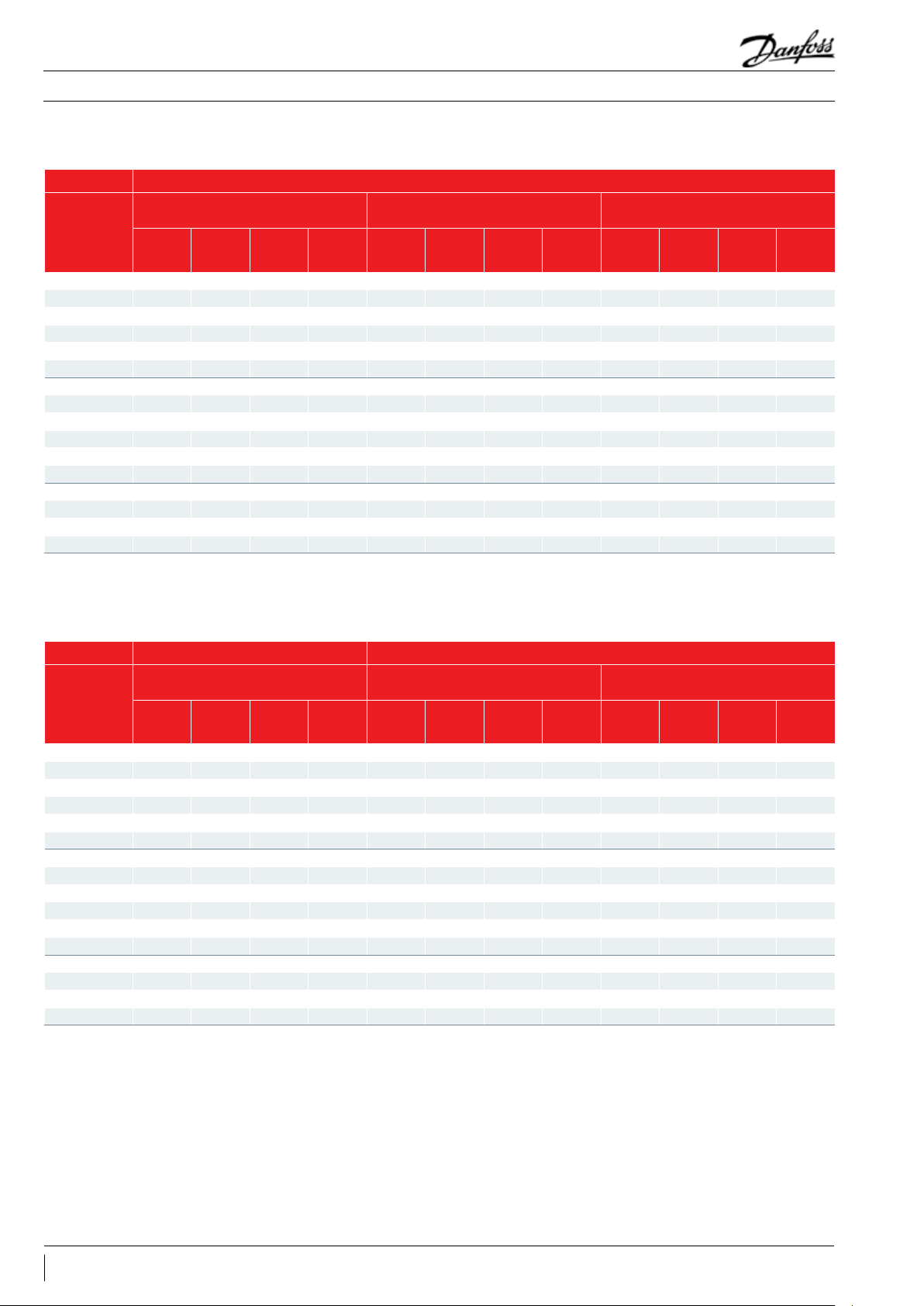
Operating envelopes
R
The operating envelopes for MT and MTZ compressors are given in the figures below and
guarantees reliable operations of the compressor for steady-state operation.
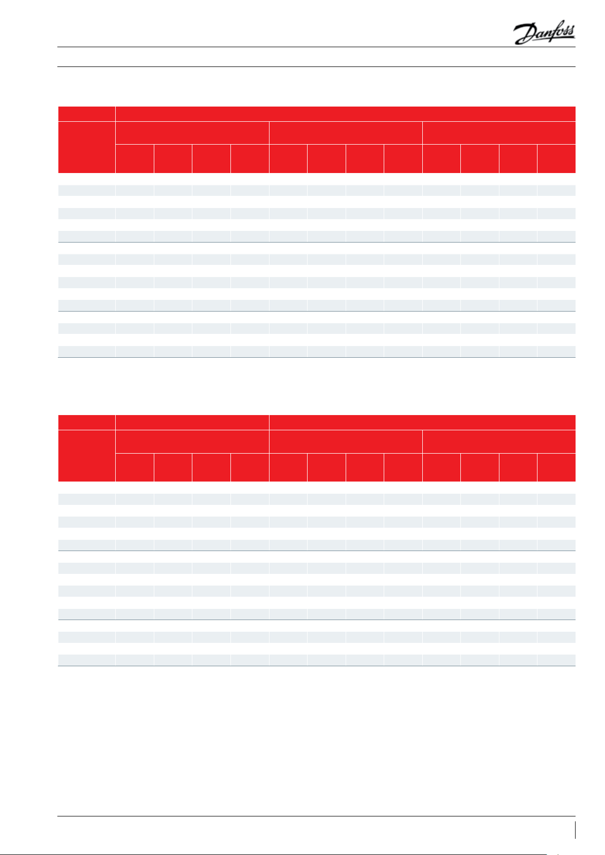
MTZ - R407C at DEW point
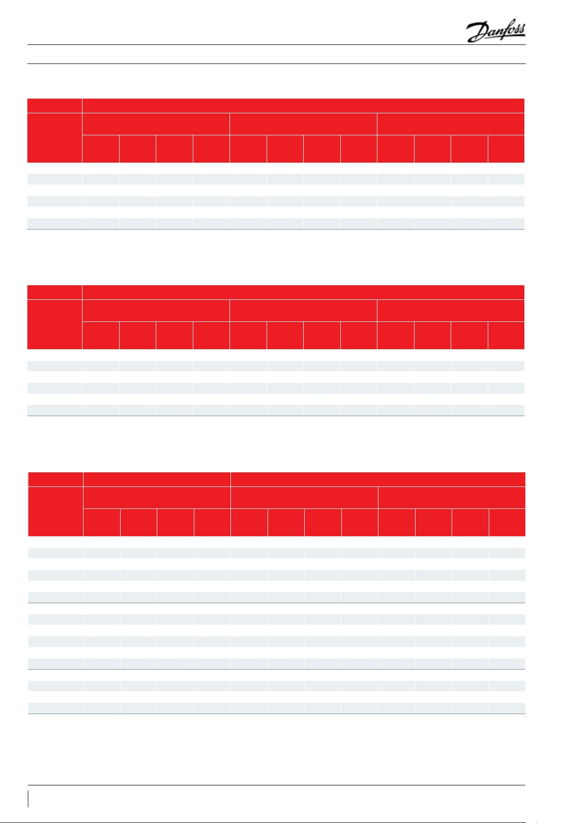
MTZ - R134a
70
65
60
55
50
45
40
35
Condensing temperature (°C)
30
-25-30 -20 -15 -10
75
70
65
60
55
50
45
40
35
Condensing temperature (°C)
30
-25-30 -20 -15 -10
S.H. = 11.1 K
Evaporating temperature (°C)
-5
-5
Evaporating temperature (°C)
0510 15 20
MTZ R134a
SH 10K
RGT 20°C
0510 15 20
S.H. = 30 K
MTZ - R404A / R507A
13AB196386425654en-021502
Page 14

Application Guidelines
MTZ – R407A at Dew Point
MTZ – R407F at Dew Point
Operating envelopes
SH 10K
RGT 20°C
SH 10K
RGT 20°C
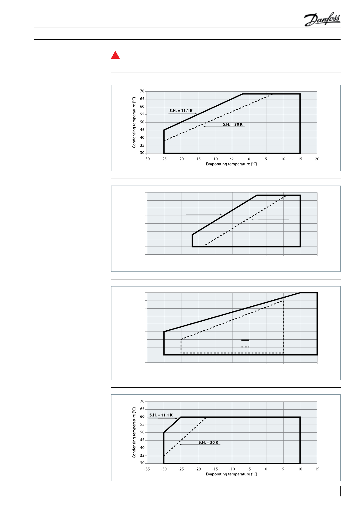
MTZ – R448A/R449A
70
65
60
55
50
45
40
35
30
25
20
15
10
5
0
-35 -30 -25 -20 -15 -10 10 15-5 05
SH 10K
RGT 20°C
SH10K RGT20
14 AB196386425654en-021502
Page 15

Application Guidelines
Operating envelopes
MTZ – R452A
MTZ – R454C/R455A
70
65
60
SH 10K
55
50
45
40
35
30
25
20
15
10
5
0
-35 -30 -25 -20 -15 -10 10 15-5 05
SH10K RGT20
70
65
60
55
50
45
40
35
30
25
20
15
10
5
0
-35 -30 -25 -20 -15 -10 10 15-5 05
SH 10K
RGT 20°C
RGT 20°C
SH10K
RGT20°C
15AB196386425654en-021502
Page 16

Application Guidelines
Operating envelopes
MTZ – R513A
Discharge temperature protection
80
75
70
65
60
55
50
45
40
35
30
25
20
15
10
5
0
-30 -25 -20 -15 -10 -5 10 15 20 2505
Even when the motor windings are
R
SH 10K
RGT 20°C
SH10K
protected against overheating by the internal
motor protection, the compressor discharge
gas temperature could exceed the maximum
allowed value of 135°C when the compressor
is operated outside its application envelope.
The most effective protection against too
high discharge gas temperature is to mount
a discharge gas thermostat. An accessory kit
is available from Danfoss which includes the
thermostat, mounting bracket and insulation.
The thermostat must be attached to the
RGT20°C
discharge line as indicated below at no more
than 150 mm from the discharge connection.
Thermostat
Discharge line
Bracket
Insulation
Zeotropic refrigerant mixtures
16 AB196386425654en-021502
Refrigerant mixtures can be either zeotropic or
azeotropic.
An azeotropic mixture (like R502 or R507A)
behaves like a pure refrigerant. During a phase
transition (from vapour to liquid or from liquid
to vapour) thecomposition of vapour and liquid
stays the same.
In a zeotropic mixture (like R407C) on the other
hand the composition of vapour and liquid
changes during the phase transition. When the
effect of this phase transition is very small, the
mixture is often called a near-azeotropic mixture.
R404A is such a near-azeotropic mixture.
The composition change causes phase shift and
temperature glide.
Page 17
Application Guidelines
Operating envelopes
Phase shift
Temperature glide
In system components where both vapour and
liquid phase are present (evaporator, condenser,
liquid receiver), the liquid phase and vapour
phase do not have the same composition. In
fact both phases form two different refrigerants.
Therefore zeotropic refrigerants need some
During the evaporating process and the
condensing process at constant pressure,
the refrigerant temperature will decrease
in the condenser and rise in the evaporator.
Therefore when speaking about evaporating
and condensing temperatures, it is important to
indicate whether this is a dew point temperature
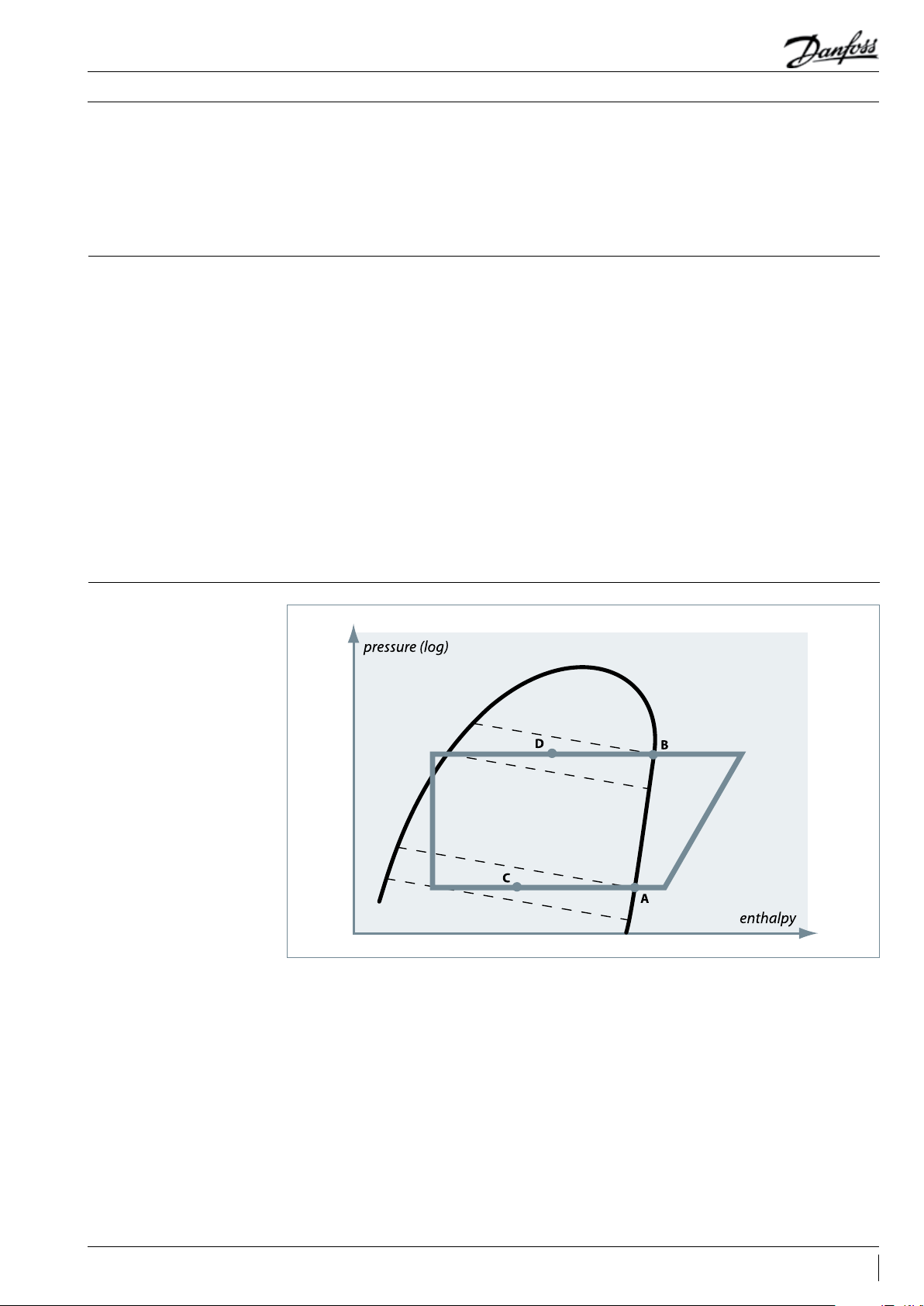
or a mean point value. In the figure below, the
dotted lines are lines of constant temperature.
They do not correspond to the lines of constant
pressure.
Points A and B are dew point values. These are
temperatures on the saturated vapour line.
special attention. Zeotropic refrigerants must
always be charged in liquid phase. Flooded
evaporators should not be applied in systems
with zeotropic refrigerants. This also applies to
near-azeotropic mixtures.
Points C and D are mean point values. These
are temperatures which correspond more or
less with the average temperature during the
evaporating and condensing process. For the
refrigerants with glide of around 6K, mean point
temperatures are typically about 2°C to 3°C lower
than dew point temperatures. According to
Asercom recommendations, Danfoss Commercial
Compressors uses dew point temperatures for
selection tables and application envelopes etc.
To obtain exact capacity data at mean point
temperatures, the mean point temperatures
must be converted to dew point temperatures
with help of refrigerant data tables from the
refrigerant manufacturer.
Dew temperature and Mean temperature for zeotropic mixtures
17AB196386425654en-021502
Page 18

Application Guidelines
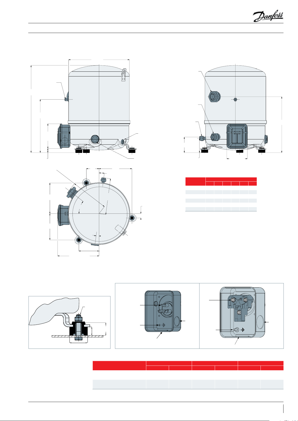
1 cylinder
Outline drawings
Bump on
single phase
LP gauge
port 1/4”
(schrader)
98
25
Suction: 142
Discharge: 142
68
(1)
/ 147
(1) (2)
Ø 224
Suction rotolock
(1)
1”
(2)
1”1/4
(1)
333
(2)
356
oil equalisation
3/8”
68
Mounting hole for PTC crankcase heater
33°
118
Threaded oil
sight glass
109
35°
(2)
Discharge rotolock
1”
68
All dimensions in mm
82
Model
1 3 4 5 6 7 9
Code
MT/MTZ018 (1) (1) (1) (1) - - -
263
MT/MTZ022 (2) (1) (1) (1) (1) - (1)
39
MT/MTZ028 (2) (1) (1) (1) (1) - (1)
MT/MTZ032 (2) (2) (2) (2) (2) (2) (2)
MT/MTZ036 (2) (2) (2) (2) (2) (2) (2)
MT/MTZ040 (2) (2) (2) - (2) - -
141
159
17
17°
Silent bloc
MT/MTZ 018 - 022 (3/4/5/6/9) 028 (3/4/5/6)
MT/MTZ022/1-028/1-032 - 036
- 040
123
Terminal box
Bolt HM8-40
23
15
Ø 31.75
Rotolock connections size Pipe sizing Rotolock valve
Suction Discharge Suction Discharge Suction Discharge
1" 1" 1/2 " 3/8" V06 V01
1"1/4 1" 5/8" 1/2 " V09 V06
Spade connectors
1/4" AMP-AWE
Earth M4-12
Knock-out Ø 21 mm
IP rating: 55 (with cable gland)
Ø 21 mm
18 AB196386425654en-021502
Page 19
413
Ø 288
265
Spade connectors
1/4" AMP-AWE
Earth M4-12
Ø 21 mm
Knock-out Ø 21 mm
Application Guidelines
2 cylinders
Schrader 1/4"
252
(1)
98
(2)
117
(1)
32
(2)
20
Suction 179
Discharge 176
145
Outline drawings
60
38°
171
Suction rotolock
1"3/4
Discharge rotolock
1"1/4
Oil equalisation
3/8"
Mounting hole for
PTC crankcase heater
74
(1)
Threaded oil sight glass
156
8°
68
All dimensions in mm
Model
1 3 4 6 7 9
Code
(2)
82
/ 98
MT/MTZ044 (1) (1) (1) (2) (1) (1)
MT/MTZ050 (2) (1) (1) (2) (1) (1)
MT/MTZ056 (2) (1) (1) (2) (1) (1)
MT/MTZ064 (2) (1) (1) (2) - (1)
21
MT/MTZ072 - (1) (1) (2) - (1)
MT/MTZ080 - (2) (1) (2) - (1)
Silent bloc
125
(1)
/ 196
188
Ø 31.75
8°
96
(2)
Terminal box for model (1)
Terminal box for model (2)
Screw
Bolt HM8-40
15
23
IP rating: 55 (with cable gland)
10-32 UNF x 9.5
Earth M4-12
Knock-out Ø 29 mm
IP rating: 54 (with cable gland)
Rotolock connections size Pipe sizing Rotolock valve
Suction Discharge Suction Discharge Suction Discharge
MT/MTZ 044 - 050 - 056 - 064 - 072 1" 3/4 1"1/4 7/ 8" 3/4" V07 V04
MT/MTZ 080 1"3/4 1"1/4 1"1/8 3/4" V02 V04
Knock-out
Ø 25.5 mm
19AB196386425654en-021502
Page 20

Ø 352
538 (2)
518 (1)
Threaded oil
Application Guidelines
4 cylinders
Outline drawings
Schrader 1/4 "
Suction rotolock
1"3/4
Discharge rotolock
1"1/4
210
117
155
232
155°
15°
246
205
Oil equalisation
3/8"
99
Mounting hole for
PTC crankcase heater
15°
246
15°
All dimensions in mm
233
125
209
98
Model
Code
3 4 6 7 9
MT/MTZ100 (1) (1) (1) (1) (1)
MT/MTZ125 (1) (1) (1) (1) (1)
MT/MTZ144 (2) (2) (2) (2) (2)
MT/MTZ160 (2) (2) (2) (2) (2)
sight glass
95
20 AB196386425654en-021502
Terminal box
Screw
10-32 UNF x 9.5
Earth M4-12
Knock-out Ø 29 mm
IP rating: 54 (with cable gland)
MT/MTZ100 - 125 - 144 - 160
Silent bloc
Knock-out
Ø 25.5 mm
Rotolock connections size Pipe sizing Rotolock valve
Suction Discharge Suction Discharge Suction Discharge
1"3/4 1"1/4 1"1/8 3/4" V02 V04
Page 21

Application Guidelines
Electrical connections and wiring
Single phase electrical characteristics
Nominal capacitor values and relays
* PSC: Permanent Split Capacitor
CSR: Capacitor Start Run
(1) Run capacitors: 440 volts
(2) Start capacitors: 330 Volts
LRA - Locked Rotor
Current (A)
Motor Code 1 5 1 5 1 5
Winding run start run start
MT/MTZ018 53 40 13 10 1.35 4.25 1.35 3.83
MT/MTZ022 53 41 17 15 1.20 2 .31 1.35 3.83
MT/MTZ028 81 51 25 20 0.68 1.84 1.07 3.26
MT/MTZ032 84 70 26.5 20 0.63 2.90 0.80 4.23
MT/MTZ036 84 60 30 22 0.63 2.90 0.80 4.23
MT/MTZ040 99 - 34 - 0.54 1.87 - MT/MTZ044 97 - 31 - 0.46 1.94 - MT/MTZ050 114 - 36 - 0.38 1.83 - MT/MTZ056 136 - 42.5 - 0.33 1.64 - MT/MTZ064 143 - 46 - 0.33 2.14 - -
Models
MT/MTZ018 JA-5 20 10 100
MT/MTZ022 JC-5 20 10 100
50 Hz
60 Hz
MT/MTZ028 JE-5 20 10 100
MT/MTZ032 JF-5 25 10 135
MT/MTZ036 JG-5 25 10 135
MT/MTZ018 JA-1 15 10 100
MT/MTZ022 JC-1 30 15 100
MT/MTZ028 JE-1 25 25 135
MT/MTZ032 JF-1 25 20 100
MT/MTZ036 JG-1 25 20 10 0
MT/MTZ040 JH-1 35 20 100
MT/MTZ044 HJ-1 30 15 135
MT/MTZ050 HK-1 30 15 135
MT/MTZ056 HL-1 35 20 200
MT/MTZ064 HM-1 30 25 235
MCC - Maximum
Continuous Current (A)
PSC/CSR* CSR only
Run capacitors (1) Start capacitors (2)
(A) µF (C) µF (B) µF
Winding resistance (Ω)
( ± 7 % at 25° C)
Start relay
3ARR3J4A4
/RVA6AMKL
3ARR3J4A4
/RVA6AMKL
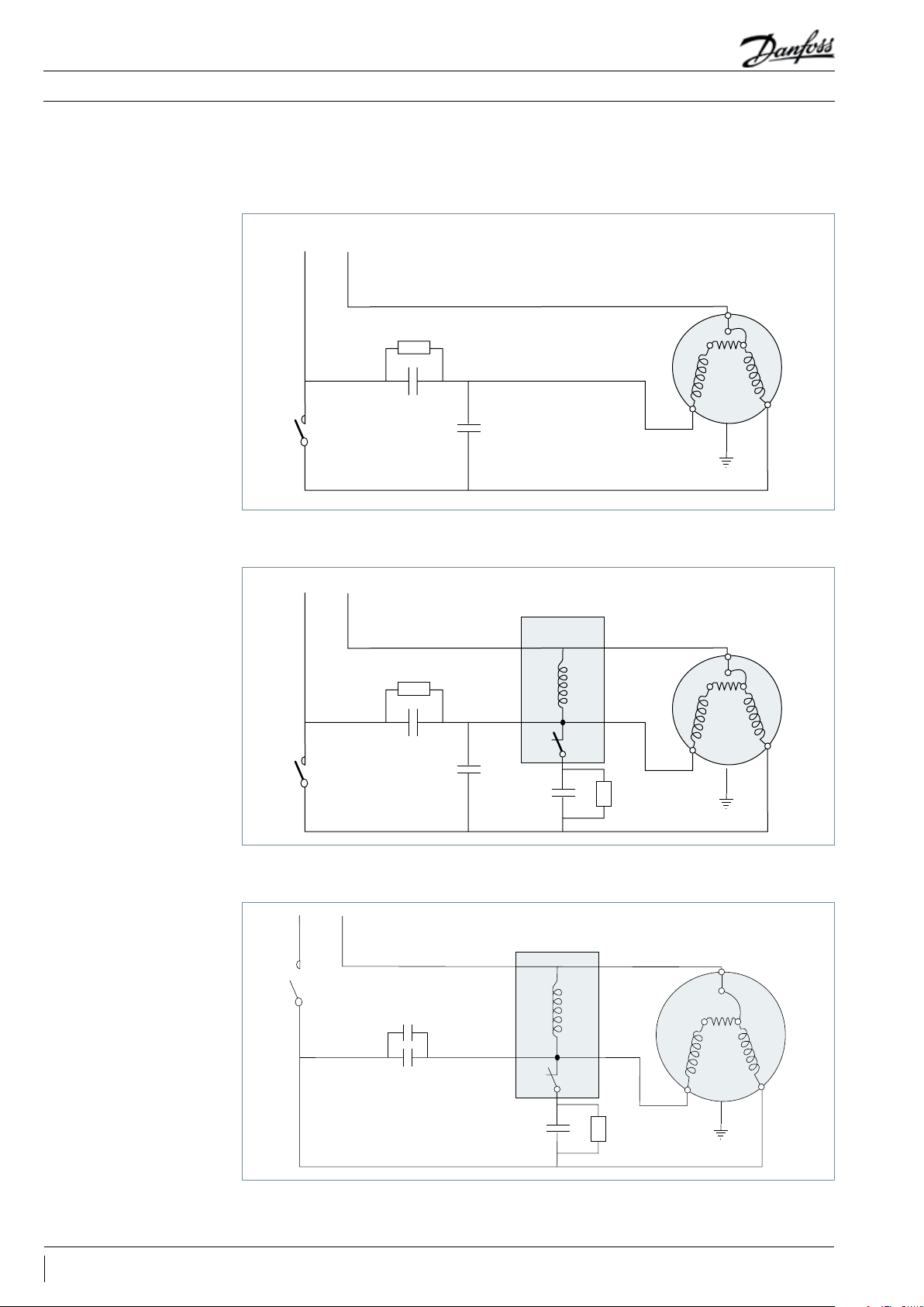
Trickle circuit
PSC wiring
CSR wiring
The trickle circuit provides the facility of heating
the compressor crankcase by feeding a small
current to the auxiliary winding and the run
capacitor (See the drawings in section “Electrical
connections and wiring”).
PSC wiring may be used for refrigerant circuits
with capillary tubes or expansion valves with
bleed ports. Pressure equalisation must be
CSR wiring provides additional motor torque
at start-up, by the use of a start capacitor in
combination with the run capacitor. This system
can be used for refrigerant circuits with capillary
tubes or expansion valves. The start capacitor is
only connected during the starting operation, a
potential relay is used to disconnect it after the
start sequence.
By using PSC or CSR starting systems,
compressor models MT / MTZ 018 - 022 can
be operated without crankcase heaters as the
heater function is provided by the trickle circuit.
For the larger single phase compressor
R
models MT / MTZ 028 - 064, the use of the PTC
crankcase heater is recommended.
ensured before start-up because of the low
starting torque characteristics of this system.
Some applications with high differential pressure
can require a very high starting torque. For such
cases the CSR starting kit can be converted to
a very high starting torque kit by an additional
start capcitor of 100 F parallel to the start
capacitor of the CSR kit. This configuration
can also be used to reduce erratic starting
at unfavourable conditions such as very low
ambient temperature or weak voltage.
21AB196386425654en-021502
Page 22
Application Guidelines
Suggested wiring diagrams
Single phase - PSC wiring
with trickle circuit
Electrical connections and wiring
230 V
IOL Motor protector
A & C Run capacitors
C Common
S Start winding (auxiliary)
R Run winding (main)
Single phase - CSR wiring
with trickle circuit
IOL Motor protector
A & C Run capacitors
B Start capacitor
C Common
S Start winding (auxiliary)
R Run winding (main)
Thermostat
230 V
Thermostat
220 kΩ - 1 W
A µF
220 kΩ - 1 W
A µF
C µF
C µF
Start relay
5
2
1
B µF
15 kΩ - 1 W
C
IOL
S
S
R
C
IOL
R
Single phase - CSR wiring
without trickle circuit
IOL Motor protector
A+C Run capacitors
B Start capacitor
C Common
S Start winding (auxiliary)
R Run winding (main)
Capacitors A and C can be replaced by
a single capacitor of size A + C
B capacitor delivered in two parts for
MT(Z)56 & 64-1
22 AB196386425654en-021502
230 V
Thermostat
CµF
Run capacitor
AµF
Run capacitor
Start capacitor
Start Relay
BµF
5
C
IOL
2
S
1
R
15 kΩ -1 w
Page 23
Application Guidelines
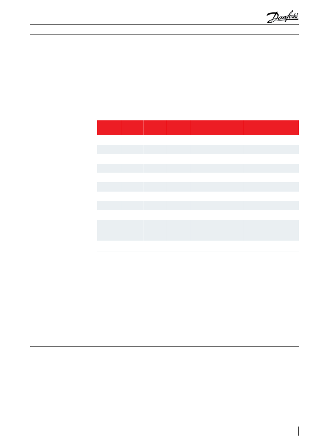
Three phase electrical characteristics
Electrical connections and wiring
LRA - Locked Rotor
Current (A)
MCC - Maximum
Continuous Current (A)
Winding resistance (Ω)
( ± 7 % at 25° C)
Motor Code 3 4 6 7 9 3 4 6 7 9 3 4 6 7 9
MT/MTZ018 38 20 - - - 9.5 5 - - - 2.58 9.34 3.41 - -
MT/MTZ022 38 20 30 - 22.5 11 6 8.5 - 6.5 2.58 11.84 3. 41 - 7. 30
MT/MTZ028 57 23 41 - 32 16 7. 5 11. 5 - 8.5 1.41 6.30 1.20 - 4.72
MT/MTZ032 60 25 44 22 35 18 8 13 5.5 9 1.32 4.45 2.01 10.11 3.40
MT/MTZ036 74 38 74 26 35 17 9 17 7 9.5 1.10 5.92 1.10 9.39 -
MT/MTZ040 98 38 74 - - 22 10 18 - - 0.89 4.05 1.10 - -
MT/MTZ044 115 48.5 77 44 78 22 9. 5 16 8.5 13 0.76 3.29 1.15 5.95 1.72
MT/MTZ050 115 48.5 77 44 78 25 11 .5 19 10 13 .5 0 .74 3.42 1.42 5.95 1.72
MT/MTZ056 130 64 105 50 72 24 14 23 11 15 0.56 2.44 0.78 3.94 1.67
MT/MTZ064 137 64 124 - 72 29 14 25 - 17.5 0.58 2.44 0.78 - 1.67
MT/MTZ072 135 80 143 - 100 30 17 27 - 18. 5 0.56 1.94 0.57 - 1.35
MT/MTZ080 140 80 132 - 102 36 19 29 - 22.5 0.49 1.94 0.57 - 1.33
MT/MTZ100 157 90 12 6 62 110 43 22 35 17 26 0. 51 2.12 0.68 3 .17 1.29
MT/MTZ 125 210 105 170 75 150 54 27 43 22 30 0.39 1.45 0.44 2.56 0.86
MT/MTZ 144 259 130 208 90 165 64 36 51 25 40 0.28 1.15 0.38 2.04 0.74
MT/MTZ 160 259 130 208 99 165 70 36 51 29 46 0.28 1.15 0.38 1.80 1.12
Winding resistance
Winding resistance is the resistance between
indicated terminal pins at 25°C (resistance value
Winding resistance is generally low and it
requires adapted tools for precise measurement.
+/- 7%).
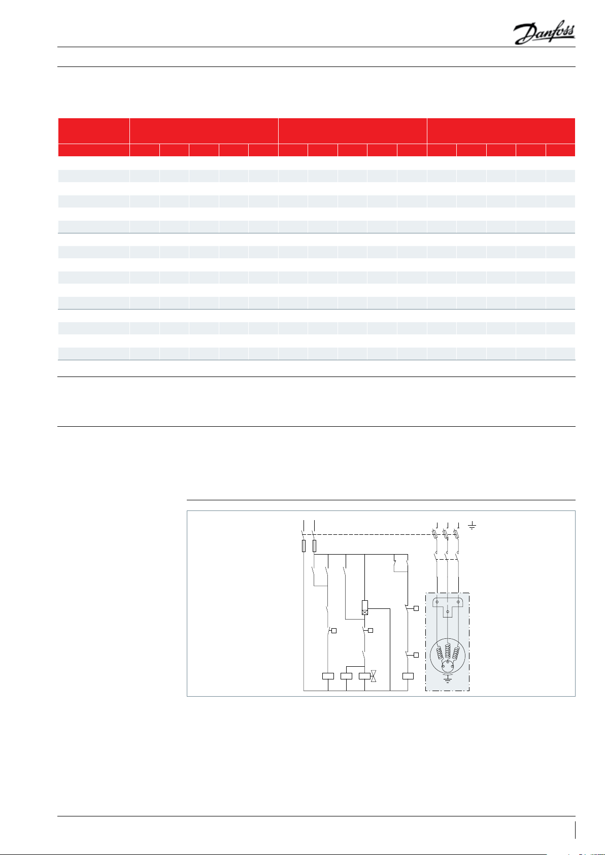
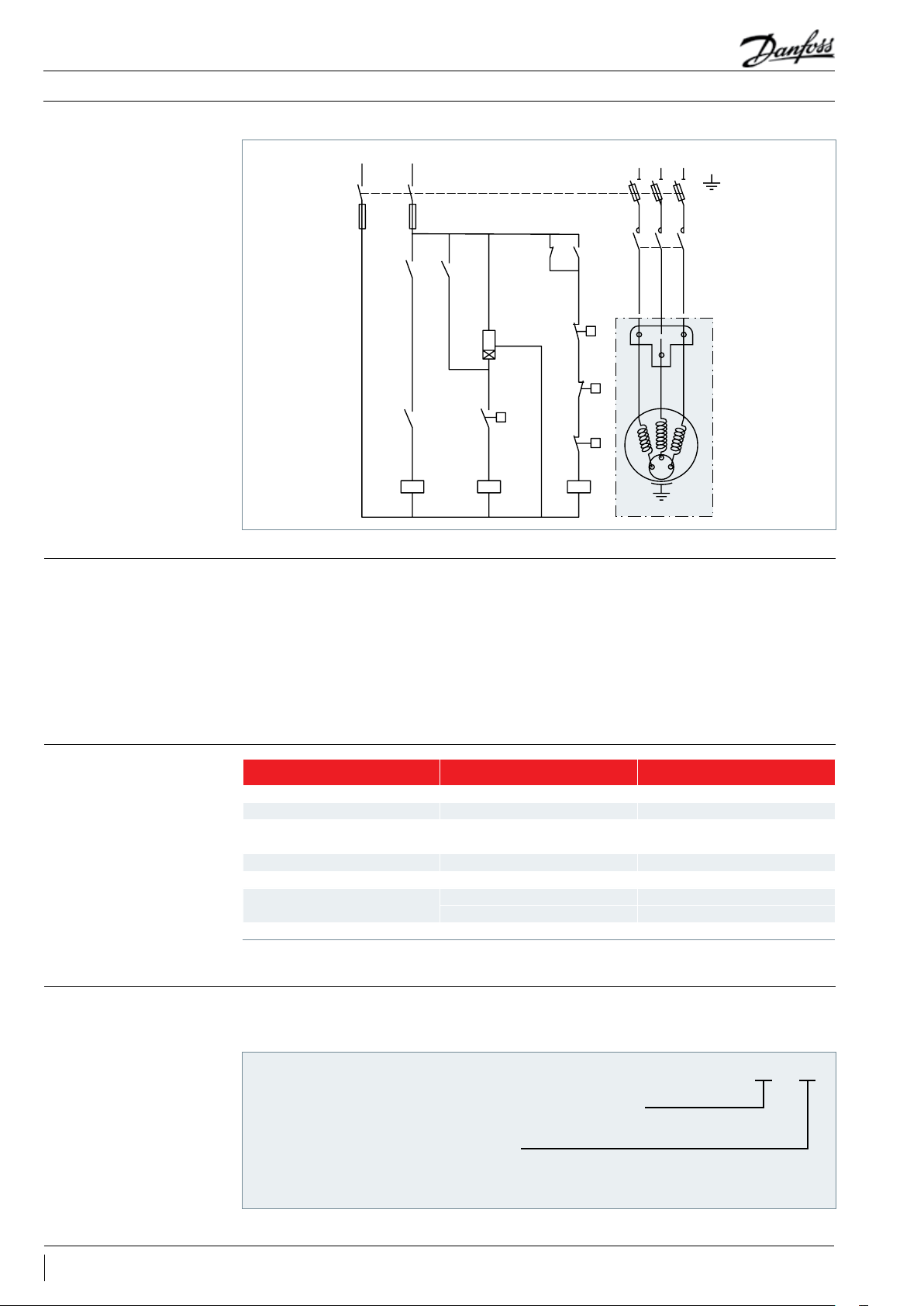
Motor protection and
suggested wiring diagrams
Suggested wiring diagram
with “one shot” pump-down
cycle and safety lock-out
relay
Control device ................................................ TH
Optional short cycle timer (3 min) ..... 180 s
Control relay .................................................... KA
Liquid Solenoid valve ............................... LLSV
Compressor contactor ................................ KM
Safety lock out relay ...................................... KS
Pump-down control & LP switch ............... LP
H.P. switch ........................................................ HP
Fused disconnect .......................................... Q1
Fuses ................................................................... F1
Compressor motor .......................................... M
Discharge gas thermostat ....................... DGT
The 3-phase compressors are protected by
an internal motor protector, connected to
the neutral point of the star connected stator
windings, the protector cuts out all 3-phases
simultaneously.
CONTROL CIRCUIT
F1F1
KM
KA KA
KS
LP
KM
KA
Note: once the overload protector has tripped it
may take up to 3 hours to reset and restart the
compressor.
For all 3-phase compressors, a PTC crankcase
heater is required.
L1 L3 L2
Q1
KA
A1
A3
180 s
A2
TH
KS
LLSV KS
KS
T1
HP
DGT
KM
T2
T3
M
23AB196386425654en-021502
Page 24
Application Guidelines
Electrical connections and wiring
Wiring diagram without
pump-down cycle
Control device ................................................ TH
Optional short cycle timer (3 min) ..... 180 s
Control relay .................................................... KA
Compressor contactor ................................ KM
Safety lock out relay ...................................... KS
High pressure switch .................................... HP
Low pressure switch ....................................... LP
Fused disconnect .......................................... Q1
Fuses ................................................................... F1
Compressor motor .......................................... M
Discharge gas thermostat ....................... DGT
Soft starters
CONTROL CIRCUIT
F1F1
KA KA
A1
A3
180 s
A2
KS
KM KA
TH
Softstarters are designed to reduce the starting
current of 3-phase AC motors.
Softstarters can be used on MTZ and MT
compressor but, in order to ensure proper
lubrication of compressor parts, the settings
must ensure that the compressor start-up time is
always less than 0.5 seconds.
L1 L3 L2
Q1
KA KS
T1
HP
LP
DGT
KS
KM
T2
T3
M
In case of use with R454C or R455A make sure
that the softstarter selected is compatible with
A2L refrigerants.
The number of starts should be limited to 6 per
hour. HP/LP pressure equalisation is required
before starting.
Voltage application range
IP rating
Motor Code Nominal voltage Voltage application range
1 208-230 V / 1 ph / 60 Hz 187 - 253 V
3 200-230 V / 3 ph / 60 Hz 180 - 253 V
4
380-400 V / 3 ph / 50 Hz 340 - 440 V
460 V / 3 ph / 60 Hz 414 - 506 V
5 220-240 V / 1 ph / 50 Hz 198 - 264 V
6 230 V / 3 ph / 50 Hz 207 - 253 V
7
500 V / 3 ph / 50 Hz 450 - 550 V
575 V / 3 ph / 60 Hz 517 - 632 V
9 380 V / 3 ph / 60 Hz* 342 - 418 V
* Some models are approved for 380 - 400 V / 3 ph / 60 Hz. Please check datasheet.
The compressor terminal boxes IP rating
according to CEI 529 are shown on the outline
The IP ratings are only valid when correctly sized
cable glands of the same IP rating are applied.
drawings section.
IP 5 5
1st numeral, level of protection against contact and foreign objects
5 complete protection against contact and against harmful dust deposits
2nd numeral, level of protection against water
4 protection against water splashing from any direction
5 protection against jets of water from any direction
MT/ MTZ 1cyl = IP55 -- MT/ MTZ 2 cyl check section outline drawings -- MT/MTZ 4cyl = IP54
24 AB196386425654en-021502
Page 25
Application Guidelines
Refrigerants and lubricants
General information
When choosing a refrigerant, different aspects
must be taken into consideration:
• Legislation (now and in the future)
• Safety
• Application envelope in relation to expected
running conditions
Additional points could influence the final
choice:
• Environmental considerations
• Standardisation of refrigerants and lubricants
• Refrigerant cost
• Refrigerant availability
• Compressor capacity and efficiency
• Compressor manufacturer recommendations
& guidelines
Only Danfoss lubricant are allowed for
Maneurop® MT & MTZ compressors.
Refrigerant Ty pe
R22 HCFC Mineral MT Mineral oil, 160P Medium / High temperature
R417A HFC Polyolester MT Polyolester oil 175PZ Medium / High temperature
R407A / C / F HFC Polyolester MTZ Polyolester oil 175PZ Medium / High temperature
R134a HFC Polyolester MTZ Polyolester oil 175PZ Medium / High temperature
R404A HFC Polyolester MTZ Polyolester oil 175PZ Medium temperature
R5 07A HFC Polyolester MTZ Polyolester oil 175PZ Medium temperature
R448A /
R449A
R454C /
R455A
R452A HFC+HFO Polyolester MTZ Polyolester oil 175PZ Medium/High temperature
HFO Polyolester MTZ Polyolester oil 175PZ Medium/High temperature
HFO Polyolester MTZ Polyolester oil 175PZ Medium/High temperature
Lubricant
type
Compressor
type
The table below gives an overview of the
different refrigerant - lubricant - compressor
combinations for Maneurop® MT & MTZ
compressors.
Danfoss lubricant Application
R22
Alternatives R22, HFC
retrofit
R407C
Alternative R22 retrofit
with HFC refrigerants
Hydrocarbons
Polyolester MT/MTZ Polyolester oil 175PZ Medium / High temperature
Danfoss does not authorise the use of hydrocarbons in Maneurop® MT/MTZ
Capacity and other data for HFC blends
refrigerants are not published in this document.
Maneurop® compressors however are suitable for
use with these refrigerants and can still be used
R22 is an HCFC refrigerant . It has a high GWP
and therefore it will be phased out in the future.
Check local legislation. Always use mineral oil
160P with R22.
A wide variety of HFC blends exist. There were
developed as temporary HCFC and HFC high
GWP alternatives. Some examples are R422A/D
Refrigerant R407C is an HFC refrigerant with
similar thermodynamic properties to those of
R22.
R407C has zero ozone depletion potential
(ODP=0). Many installers and OEMs consider
R407C to be the standard alternative for
R22. R407C is a zeotropic mixture and has a
temperature glide of about 6 K. For more specific
compressors
as replacements in existing installations, see
technical news FRCC.EN.049. and FRCC.EN.085.
for more information on retrofit.
The Maneurop® MT compressor is supplied with
an initial mineral oil charge.
- R427A, ... Retrofit technical news have been
issued to advice about use of these refrigerants.
information about zeotropic refrigerants; refer to
section "zeotropic refrigerant mixtures". R407C
must be charged in the liquid phase.
Always use the Maneurop® MTZ compressors
with Danfoss 175PZ polyolester oil, which is
supplied with the MTZ compressor.
25AB196386425654en-021502
Page 26

Application Guidelines
Refrigerants and lubricants
R134a
R404A
R507A
Refrigerant R134a is an HFC refrigerant with zero
ozone depletion potential (ODP = 0).
For applications with high evaporating and
high condensing temperatures, R134a is the
Refrigerant R404A is an HFC refrigerant with
zero ozone depletion potential (ODP = 0).
R404A is especially suitable for low evaporating
temperature applications but it can also be
applied to medium evaporating temperature
applications. R404A is a mixture and has a very
small temperature glide, and therefore must
be charged in its liquid phase, but for most
other aspects this small glide can be neglected.
Because of the small glide, R404A is often called
Refrigerant R507A is an HFC refrigerant with
no ozone depletion potential (ODP = 0). As
with R404A, R507A is particularly suitable for
low evaporating temperature applications but
it can also be used for medium evaporating
temperature applications. R507A is an azeotropic
mixture with no temperature glide. For low
ideal choice. R134a is a pure refrigerant and has
zero temperature glide. For R134a applications
always use the Maneurop® MTZ compressor with
Danfoss 175PZ polyolester oil which is supplied
with the MTZ compressor.
a near-azeotropic mixture. For more information
refer to section «zeotropic refrigerant mixtures».
For low evaporating temperature applications
down to -45°C, Maneurop® NTZ compressors
should be used. Refer to the NTZ selection and
application guidelines. For medium temperature
R404A applications, always use the Maneurop®
MTZ compressor with 175PZ polyolester oil
which is supplied with the MTZ compressor.
evaporating temperature applications down to
-45°C, Maneurop® NTZ compressor should be
used. Refer to the NTZ selection and application
guidelines. For medium temperature R507A
applications, always use the Maneurop® MTZ
compressor and Maneurop® 175PZ polyolester oil
which is supplied with the MTZ compressor.
R407A
R407F
R448A/R449A
Refrigerant R407A is an HFC with similar
thermodynamic properties to those of R404A,
R407A is a zeotropic refrigerant and has a
temperature glide of about 6,6K. For more
specific information about zeotropic refrigerant,
refer to section “zeotropic refrigerants mixtures”
Refrigerant R407F is an HFC with similar
thermodynamic properties to those of R404A,
R407F is a zeotropic refrigerant and has a
temperature glide of about 6,4K. For more
specific information about zeotropic refrigerant,
refer to section “zeotropic refrigerants mixtures”
and read FRCC.EN.085. R407F must be charged
R448A/R449A is an HFO/HFC Blend, with
similar thermodynamic properties to those
of R404A or R22. R448A/R449A is a Zeotropic
refrigerant and has a temperature glide of about
6,1/6,3K. For more specific information about
zeotropic refrigerant, refer to section “zeotropic
refrigerants mixtures” and read FRCC.EN.085.
and read FRCC.EN.085. R407A must be charged
in liquid phase, R407A GWP is stated at 2107
[CO=1,0]. Always use the Maneurop MTZ
compressors with danfoss 175PZ polyolester oil,
which is supplied with the MTZ compressors.
in liquid phase, R407F GWP is stated at 1825
[CO=1,0]. R407F is mainly suitable for high &
medium temperature application- Always use
the Maneurop MTZ compressors with danfoss
175PZ polyolester oil, which is supplied with the
MTZ compressors.
R448A/R449A must be charged in liquid phase,
R448A GWP is stated at 1387/1397 [CO=1,0].
Always use the Maneurop MTZ compressors with
Danfoss 175PZ polyolester oil, which is supplied
with the MTZ compressors.
26 AB196386425654en-021502
Page 27

Application Guidelines
Refrigerants and lubricants
R452A
R454C/R455A
R513A
R452A is an HFO/HFC Blend, with similar
thermodynamic properties to those of R404A
or R22. R452A is a Zeotropic refrigerant and
has a temperature glide of about 4K. For more
specific information about zeotropic refrigerant,
refer to section “zeotropic refrigerants mixtures”
R454C/R455A is an HFO Blend, with similar
thermodynamic properties to R404A. R454C/
R455A is a Zeotropic refrigerant and has
a temperature glide of about 6K /12K and
therefore must be charged in liquid phase.
For R454/R455A C GWP is stated below 150 limit.
Always use the Maneurop MTZ compressors with
Danfoss 175PZ polyolester oil.
R454C/R455A is classified A2L with low
flammability properties. Please refer to European
regulation and directives about the use of
R513A is an HFO/HFC Blend, with similar
thermodynamic properties to the R134a. R513A is
a Azeotrope refrigerant with a negligible glide.
R513A has zero ozone depletion potential
(ODP=0) and a Global Warming Potential (AR5)
at 573 [CO=1] . Always use the Maneurop® MTZ
compressors with Danfoss 175PZ polyolester oil.
and read FRCC.EN.085. R452A must be charged
in liquid phase, R452A GWP is stated at 1945
[CO=1,0]. Always use the Maneurop® MTZ
compressors with Danfoss 175PZ polyolester oil,
which is supplied with the MTZ compressors.
refrigerant of the A2L safety group (EN378,
EN60335). Outside Europe refer to the local
regulation.
R
With R454C/R455A, liquid migration to the
compressor have to be avoid:
- Maintain adequate superheat setting of
minimum 8-10K
- Use solenoid valve on the liquid line and pump
down is recommended.
- Use a crankase heater to avoid dissolution of
the lubricant.
With R513A, liquid migration to the
R
compressor have to be avoid:
- Maintain adequate superheat setting of
minimum 8-10K
- Use solenoid valve on the liquid line and pump
down is recommended.
- Use a crankase heater to avoid dissolution of
the lubricant.
Hydrocarbons
Hydrocarbons such as propane, isobutane
etc. are extremely flammable. Danfoss does
not authorise the use of hydrocarbons with
Maneurop® MT or MTZ compressors in any way,
even with a reduced refrigerant charge.
27AB196386425654en-021502
Page 28

Application Guidelines
System design recommendations
Piping design
Suction lines
Oil in a refrigeration circuit is required to
lubricate moving parts in the compressor. During
normal system operation small oil quantities
will continuously leave the compressor, with the
discharge gas. With good system piping design
this oil will return to the compressor. As long
as the amount of oil circulating through the
system is small it will contribute to good system
operation and improved heat transfer efficiency.
However, too large amounts of oil in the system
will have a negative effect on condenser and
evaporator efficiency. If, in a poorly designed
Horizontal suction line sections shall have a
slope of 0.5% in the direction of refrigerant flow
(5 mm per meter). The cross-section of horizontal
suction lines shall be such that the resulting
gas velocity is at least 4 m/s. In vertical risers, a
gas velocity of 8 to 12 m/s is required to ensure
proper oil return. A U-trap is required at the
foot of each vertical riser. If the riser is higher
than 4 m, additional U-traps are required for
each additional 4 meters. The length of each
U-trap must be as short as possible to avoid the
accumulation of excessive quantities of oil (see
figure below).
system, the amount of oil returning to the
compressor is lower than the amount of oil
leaving the compressor, the compressor will
become starved of oil and the condenser,
evaporator and/or refrigerant lines will become
filled with oil. In such situations, additional oil
charge will only correct the compressor oil level
for a limited period of time and increase the
amount of surplus oil in the rest of the system.
Only correct piping design can ensure a good oil
balance in the system.
Gas velocities higher than 12 m/s will not
contribute to significantly better oil return.
However they will cause higher noise levels
and result in higher suction line pressure drops
which will have a negative effect on the system
capacity.
For compressors mounted in parallel, the
common suction riser should be designed as
a double riser. Also refer to the News bulletin
"Mounting instructions for installation of
Maneurop® compressors in parallel " and "Parallel
application guidelines".
Note that the suction rotolock valves, which
can be ordered from Danfoss as accessories, are
designed for average pipe sizes, selected for
systems running at nominal conditions.
Discharge line When the condenser is mounted above the
compressor, a loop above the condenser and a
U-trap close to the compressor are required to
prevent liquid draining from the condenser into
the discharge line during standstill.
The pipe sizes selected for specific systems may
differ from these recommended sizes.
It is recommended that the suction lines are
insulated to limit suction gas superheat.
28 AB196386425654en-021502
Page 29

Application Guidelines
System design recommendations
Oil charge and oil separator
Filter driers
Operating limits
High pressure
Low pressure
In most installations the initial compressor oil
charge will be sufficient. In installations with line
runs exceeding 20 m, or with many oil traps or an
installations with the risk of slow oil return such
as in multiple evaporator or multiple condenser
installations, an oil separator is recommended.
oil separator, additional oil may be required. In
For new installations with MTZ compressors
Danfoss recommends using the Danfoss DML
filter driers containing activated alumina are
recommended.
100%-molecular sieve, solid core filter drier.
Molecular sieve filter driers with loose beads
from third party suppliers shall be avoided.
The drier is to be oversized rather than
undersized. When selecting a drier, always
take into account its capacity (water content
For servicing of existing installations where acid
formation is present the Danfoss DCL solid core
A high pressure safety switch is required to stop
the compressor, should the discharge pressure
exceed the values shown in the table below. The
high pressure switch can be set to lower values
depending on the application and ambient
conditions.
R
A low pressure safety switch is recommended to avoid compressor operation at too lower
capacity), the system refrigerating capacity and
the system refrigerant charge.
R
The HP switch must either be in a lockout
circuit, or be a manual reset device to prevent
compressor cycling around the high pressure
limit. When a discharge valve is used, the HP
switch must be connected to the service valve
gauge port, which cannot be isolated.
suction pressures.
MT MTZ
R22
160P
Test pressure low side 25 25 25 25 25 25 25 25 25 25 25 25 25
Working pressure
range high side
Working pressure
range low side
*Relief valve opening
pressure difference
*Relief valve closing
pressure difference
* Relief v alve fitted on 2 and 4 c yl.
10.9 - 27.7 9.32 - 25.5 11.6 - 25.8 12.5 - 29.4 12.1 - 24 7.87 - 22.6 13.2 - 27.7 12. 5-2 7.3 11.7-25.9 11.7-26 .0 5.2 - 22.3 8.37-23.36 5.6-22.3
1.01 - 6.89 0.54 - 5.66 0.53 - 5.94 1.43 - 6.55 0.99 - 6.25 0.06 - 4.72 1.04 - 7.2 0.84-6.69 0.6- 6.07 0.6-6.08 0.4 - 5.2 0 .21- 5.12 5.6-22.3
Low ambient temperature
operation
R417A
175P Z
30 30 30 30 30 30 30 30 30 30 30 30 30
8 8 8 8 8 8 8 8 8 8 8 8 8
R4 07A
175P Z
R407C
175P Z
R407F
175P Z
R134 a
175P Z
R404A/R507A
175P Z
bar (g)
At low ambient temperatures, the condensing
temperature and condensing pressure in air
cooled condensers will decrease.
R452A R449A R448A R454 C R513 A R455A
valve in the discharge line is required and
special care should be taken when designing the
discharge line.)
• Reduce air flow to condensers.
This low pressure may be insufficient to supply
enough liquid refrigerant to the evaporator. As a
result the evaporator temperature will strongly
decrease with the risk of frosting. At compressor
start-up, the compressor can pull a deep vacuum
Other problems can also occur when the
compressor is operating at low ambient
temperature. During shut down periods, liquid
refrigerant can migrate to a cold compressor.
and it can be switched off by the low pressure
protection. Depending on the low pressure
switch setting and delay timer short cycling can
For such conditions a belt-type crankcase heater
is strongly recommended.
occur. To avoid these problems, several solutions
are possible, based on reducing condenser
capacity:
• Indoor location of condensers
Note that with 100% suction gas cooled motors,
Maneurop® compressors can be externally
insulated.
• Liquid flooding of condensers (note: this
solution requires extra refrigerant charge, which
can introduce other problems. A non-return
Refer to section "Liquid refrigerant control &
charge limits" for more details.
29AB196386425654en-021502
Page 30

Application Guidelines
Operating voltage and cycle rate
Operating voltage range
System design recommendations
The operating voltage limits are shown in
the table from section “Compressor model
designation”. The voltage applied to the
motor terminals must always be within these
table limits. The maximum allowable voltage
|V
% voltage unbalance:
Vavg = Mean voltage of phases 1, 2 and 3
V1-2 = Voltage between phases 1 and 2
avg - V1-2 |+|Vavg - V1-3 |+|Vavg - V2-3 |
unbalance for 3-phase compressors is 2%.
Voltage unbalance causes high current draw
on one or more phases, which in turn leads to
overheating and possible motor damage.
Voltage unbalance is given by the formula:
x 100
avg
2 xV
V1-3 = Voltage between phases 1 and 3
V2-3 = Voltage between phases 2 and 3.
Cycle rate limit
R
There may be no more than 12 starts per
hour (6 when a soft start accessory is used). A
higher number reduces the service life of the
motor-compressor unit. If necessary, use an antishort-cycle timer in the control circuit.
A time-out of six minutes is recommended.
Liquid refrigerant control and charge limit
Refrigeration compressors are basically designed
as gas compressors. Depending on the
compressor design and operating conditions,
most compressors can also handle a limited
amount of liquid refrigerant. Maneurop® MT
and MTZ compressors have a large internal
volume and can therefore handle relatively large
amounts of liquid refrigerant without major
problems. However even when a compressor
can handle liquid refrigerant, this will not be
favourable to its service life. Liquid refrigerant
can dilute the oil, wash oil out of bearings and
result in high oil carry over, resulting in loss of
Off-cycle migration During system standstill and after pressure
equalisation, refrigerant will condense in the
coldest part of the system. The compressor can
easily be the coldest spot, for example when it
is placed outside in low ambient temperatures.
After a while, the full system refrigerant charge
can condense in the compressor crankcase. A
large amount will dissolve in the compressor
oil until the oil is completely saturated with
refrigerant. If other system components are
located at a higher level, this process can be
even faster because gravity will assist the liquid
refrigerant to flow back to the compressor. When
the compressor is started, the pressure in the
crankcase decreases rapidly.
The system must be designed in such a way
to guarantee a minimum compressor running
time in order to provide proper oil return and
sufficient motor cooling after starting.
Note that the oil return rate varies as a function
of the system design.
oil from the sump. Good system design can
limit the amount of liquid refrigerant in the
compressor, which will have a positive effect on
the compressor service life.
Liquid refrigerant can enter a compressor in
different ways, with different effects on the
compressor.
R
The liquid migration to the compressor
must be avoided by maintaining adequate
superheat setting of min. 8-10K.
At lower pressures the oil holds less refrigerant,
and as a result part of the refrigerant will
violently evaporate from the oil, causing the oil
to foam. This process is often called “boiling”.
The negative effects from migration on the
compressor are:
• oil dilution by liquid refrigerant
• oil foam, transported by refrigerant gas and
discharged into the system, causing loss of oil
and in extreme situations risk for oil slugging
• in extreme situations with high system
refrigerant charge, liquid slugging could occur
(liquid entering the compressor cylinders).
Liquid floodback during
operation
30 AB196386425654en-021502
During normal and stable system operation,
refrigerant will leave the evaporator in a
superheated condition and enter the compressor
as a superheated vapour.
Normal superheat values at compressor suction
are 5 to 30 K. However the refrigerant leaving
the evaporator can contain an amount of liquid
refrigerant due to different reasons:
• wrong dimensioning, wrong setting or
malfunction of expansion device
• evaporator fan failure or blocked air filters.
In these situations, liquid refrigerant will
continuously enter the compressor.
Page 31

Application Guidelines
System design recommendations
Liquid floodback at change
over cycles in reversible heat
pumps
Liquid floodback and zeotropic refrigerants
Crankcase heater
The negative effects from continuous liquid
floodback are:
• permanent oil dilution
In heat pumps, change over from cooling to
heating cycles, defrost and low load short cycles
may lead to liquid refrigerant floodback or
saturated refrigerant return conditions.
Liquid floodback in systems working with a
zeotropic refrigerant introduces additional
negative effects. e.g. R407C, R454C, R455A. A part
of the refrigerant leaves the evaporator in liquid
phase and this liquid has a different composition
than the vapour.
A crankcase heater protects against the
R
off-cycle migration of refrigerant and proves
effective if oil temperature is maintained 10
K above the saturated LP temperature of the
refrigerant. Tests must thereby be conducted
to ensure that the appro-priate oil temperature
is maintained under all ambient conditions. A
PTC crankcase heater is recommended on all
stand-alone compressors and split systems. PTC
crankcase heaters are self-regulating.
Under extreme conditions such as very low
ambient temperature a belt type crankcase
heater could be used in addition to the PTC
heater, although this is not a preferred solution
for 1 and 2 cylinder compressors. The belt
crankcase heater must be positioned on the
compressor shell as close as possible to the oil
sump to ensure good heat transfer to the oil.
• in extreme situations with high system
refrigerant charge and large amounts of
floodback, liquid slugging could occur.
The negative effects are:
• oil dilution
• in extreme situations with high system
refrigerant charge and large amounts of
floodback, liquid slugging could appear.
This new refrigerant composition may result in
different compressor operating pressures and
temperatures.
Belt crankcase heaters are not self-regulating.
Control must be applied to energise the belt
heater once the compressor has been stopped
and then to de-energise it while the compressor
is running. The belt heater must be energised 12
hours before restarting the compressor following
an extended down period.
If the crankcase heater is not able to maintain the
oil temperature at 10 K above the saturated LP
temperature of the refrigerant during off cycles
or if repetitive floodback is present a the Liquid
Line Solenoid Valve (LLSV) + pump-down cycle
is required, eventually in conjunction with a
suction accumulator.
R
Crankcase heater or PTC crankcase heater
always has to be use when refrigerant R454C/
R455A or R513A is used.
Liquid line solenoid valve &
pump-down
Suction accumulator
In refrigeration applications, the Liquid Line
Solenoid Valve (LLSV) is highly recommended.
During the off-cycle, the LLSV isolates the liquid
charge in the condenser side, thus preventing
against refrigerant transfer or excessive
migration of refrigerant into the compressor.
Furthermore, when using a LLSV in conjunction
with a pump-down cycle, the quantity of
refrigerant in the low-pressure side of the system
will be reduced.
A suction accumulator offers considerable
protection against refrigerant floodback at
start-up, during operation or after the defrost
operation. This device also helps to protect
against off-cycle migration by means of
providing additional internal free volume to the
low pressure side of the system.
A pump-down cycle design is required when
evaporators are fitted with electric defrost
heaters.
Liquid line solenoid valve and pump down have
to be use with refrigierant R513A.
The suction accumulator must be selected in
accordance with the accumulator manufacturer
recommendations. As a general rule, Danfoss
recommends to size the accumulator for at least
50% of the total system charge. Tests however
must be conducted to determine the optimal
size.
31AB196386425654en-021502
Page 32
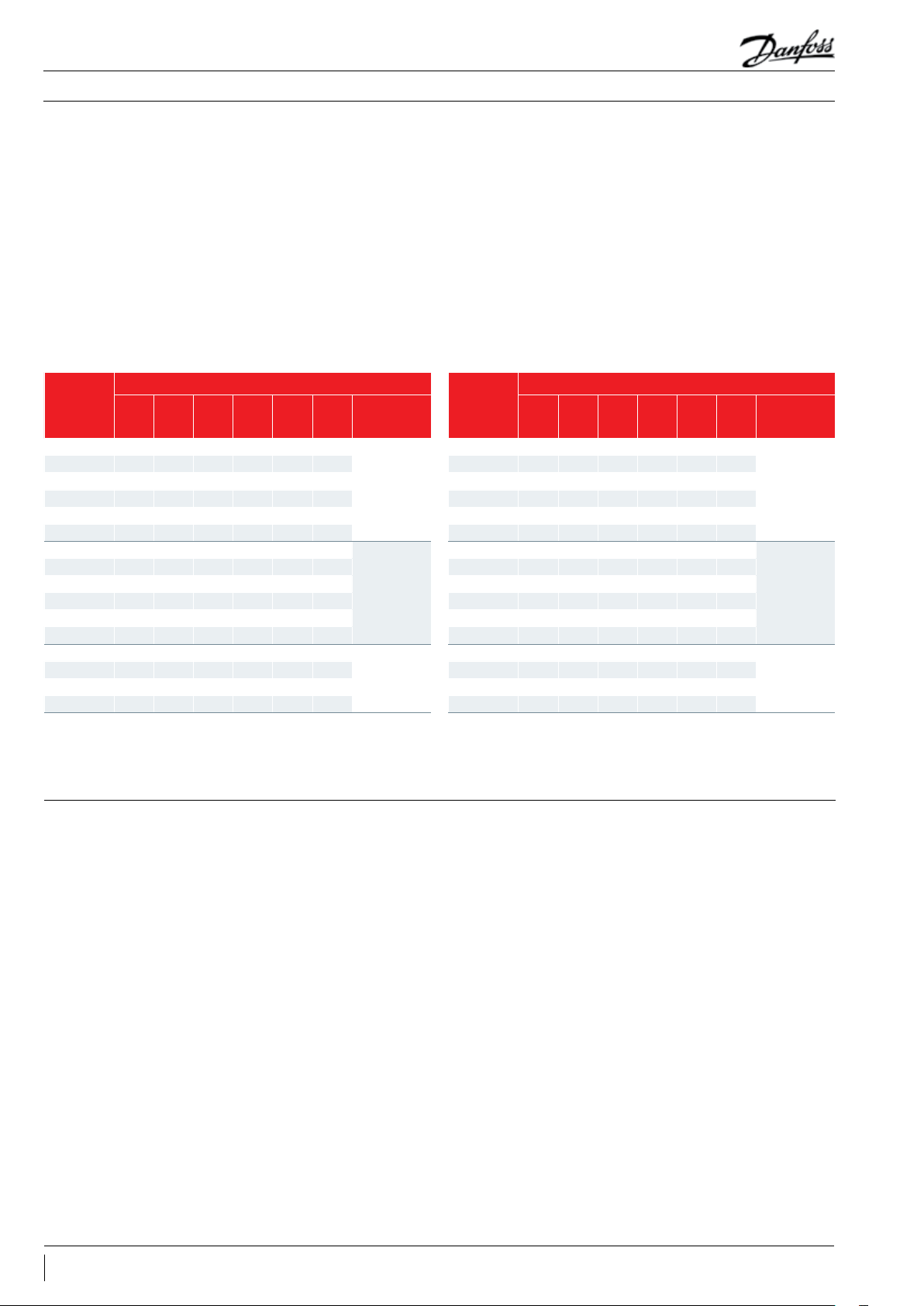
Application Guidelines
Sound and vibration management
Sound
Running compressors cause sound and vibration.
Both phenomena are closely related.
Because Maneurop® compressors are 100%
suction gas cooled, and require no body cooling,
they can be insulated. Values for the sound
Sound produced by a compressor is transmitted
in every direction by the ambient air, the
mounting feet, the pipework and the refrigerant
in the pipework.
reduction achieved with acoustic hoods are
shown also in the table on the right. For inside
mounted compressors, sound insulation of the
plantroom is an alternative to sound insulation of
the compressor.
The easiest way to reduce the sound transmitted
through ambient air is to fit a Danfoss acoustic
hood accessory.
Sound transmitted by mounting feet, pipework
and refrigerant should be treated the same way
as for vibration. Please refer to the next section.
50Hz
MTZ018- 4 73 74 73 76 75 71*
MTZ022-4 74 74 74 74 75 69*
MTZ028-4 75 72 73 73 75 68*
MTZ032-4 73 73 73 73 72 68*
MTZ036-4 72 72 72 72 73 67*
MTZ040-4 72 73 75 72 73 67
MTZ044-4 80 80 80 80 - 76*
MTZ050-4 83 83 83 83 - 79*
MTZ056-4 81 81 80 79 - 75*
MTZ064-4 80 80 80 80 - 76*
MTZ072-4 79 79 79 79 - 75*
MTZ080-4 80 80 79 80 - 76
MTZ100-4 85 84 84 82 - 79*
MT Z125 -4 84 84 84 84 - 81*
MTZ144 -4 83 83 83 83 - 80*
MTZ160-4 83 84 83 81 - 78
* Provisional Data
Sound power level for MTZ
As first approach, use these figures with -3 dB(A) reduction on the R404A sound power for MT models applied with R22.
** Acoustic hood accessory can reduce noise level by 6 to 10 dBA (depending on the operating conditions and models).
R404A R448A R449A R452A R454C R513 A
Acoustic hood
accessory**
120Z0575
120Z0576
120Z0577
60Hz
MTZ018- 4 76 75 73 76 72 71*
MTZ022-4 77 77 77 77 77 72*
MTZ028-4 74 73 74 73 76 68*
MTZ032-4 74 74 74 74 73 69*
MTZ036-4 73 73 73 73 76 68*
MTZ040-4 75 73 74 74 74 69
MTZ044-4 83 81 82 81 - 77*
MTZ050-4 86 86 86 86 - 82*
MTZ056-4 84 84 84 84 - 76*
MTZ064-4 83 83 83 83 - 78*
MTZ072-4 82 82 82 82 - 77*
MTZ080-4 82 81 80 82 - 77
MTZ100-4 88 86 86 85 - 81*
MT Z125 -4 87 87 87 87 - 83*
MTZ144 -4 86 86 86 86 - 82*
MTZ160-4 86 85 84 84 - 80
R404A R448A R449A R452A
Te=-10°C / TC=45°C / SH=10
R454C/
R513A
R455A
Acoustic hood
accessory**
120Z0575
120Z0576
120Z0577
Vibration The mounting grommets delivered with the
compressor should always be used. They reduce
the vibration transmitted by the compressor
mounting feet to the base frame.
The base on which the compressor is mounted
should be sufficiently rigid and of adequate mass
to ensure the full effectiveness of the mounting
grommets.
The compressor should never be directly
mounted to the base frame without the
grommets, otherwise high vibration transmission
would occur and the compressor service life
reduced. Suction and discharge lines must
have adequate flexibility in 3 planes. Eventually
vibration absorbers may be required.
Care must be taken to avoid tubing having
resonant frequencies close to those of the
compressor frequency.
Vibration is also transmitted by the refrigerant
gas. Maneurop® compressors have built in
mufflers to reduce this vibration.
To further reduce vibration an extra muffler can
be installed.
Note: Maneurop® MT & MTZ compressors have
been designed and qualified for stationary
equipment used in A/C and Refrigeration
applications.
Danfoss doesn’t warrant these compressors
for use in mobile applications, such as trucks,
railways, subways, etc...
32 AB196386425654en-021502
Page 33

Application Guidelines
Installation and service
System cleanliness System contamination is one of the main factors
affecting equipment reliability and compressor
service life.
Therefore it is important to ensure system
cleanliness when manufacturing a refrigeration
system. During the manufacturing process,
system contamination can be caused by:
• Brazing and welding oxides
• Filings and particles from removing burrs from
pipe-work
• Brazing flux
• Moisture and air.
Only use clean and dehydrated refrigeration
grade copper tubes and silver alloy brazing
Compressor handling, mounting and connection to the system
Compressor handling
Maneurop® MT and MTZ compressors are
provided with a lifting lug. This lug should
always be used to lift the compressor. Once the
compressor is installed, the compressor lifting
material. Clean all parts before brazing and
always purge nitrogen or CO
through the
2
pipes during brazing to prevent oxidation. If
flux is used, take every precaution to prevent
leakage into the piping. Do not drill holes (e.g.
for schräder valves) in parts of the installation
that are already completed, when filings and
burrs can not be removed. Carefully follow the
instructions below regarding brazing, mounting,
leak detection, pressure test and moisture
removal. All installation and service work shall
only be done by qualified personnel respecting
all procedures and using tools (charging systems,
tubes, vacuum pump, etc.) dedicated for the
refrigerant that will be used.
lug should never be used to lift the complete
installation.
Keep the compressor in an upright position
during handling.
Compressor mounting
Compressor connection to
the system
Mount the compressor on a horizontal plane
with a maximum slope of 3 degrees. All
compressors are supplied with three or four
rubber mounting grommets, each complete with
metal sleeves and nuts and bolts. Refer to the
These grommets largely attenuate the
compressor vibration transmitted to the base
frame. The compressor must always be mounted
with these grommets. Refer to the table below
for torque values.
section “Outline drawings”.
Designation Recommended torque (Nm)
Cable screw of T connector in electrical box screw 10/32 - UNF x 3 3
1" 80
Rotolock valves and solder sleeves
Mounting grommet bolts 1-2 / 4 cylinder 15 / 50
Oil sight glass - 50
Oil equalisation connection 1-2 / 4 cylinder 30 / 45
New compressors have a protective nitrogen
holding charge.
1"1/4 90
1"3/4 110
valves to the pipework before the compressor
is mounted. When all brazing is finished and
when the total system is ready, the compressor
R
The suction and discharge caps should
only be removed just before connecting the
compressor to the installation to avoid air and
caps can be removed and the compressor can
be connected to the system with a minimum
exposure to ambient air.
moisture entering the compressor.
If this procedure is not possible, the sleeves
Whenever possible the compressor must be the
last component to be integrated in the system. It
or valves may be brazed to the pipes when
mounted on the compressor.
is advisable to braze the solder sleeves or service
33AB196386425654en-021502
Page 34
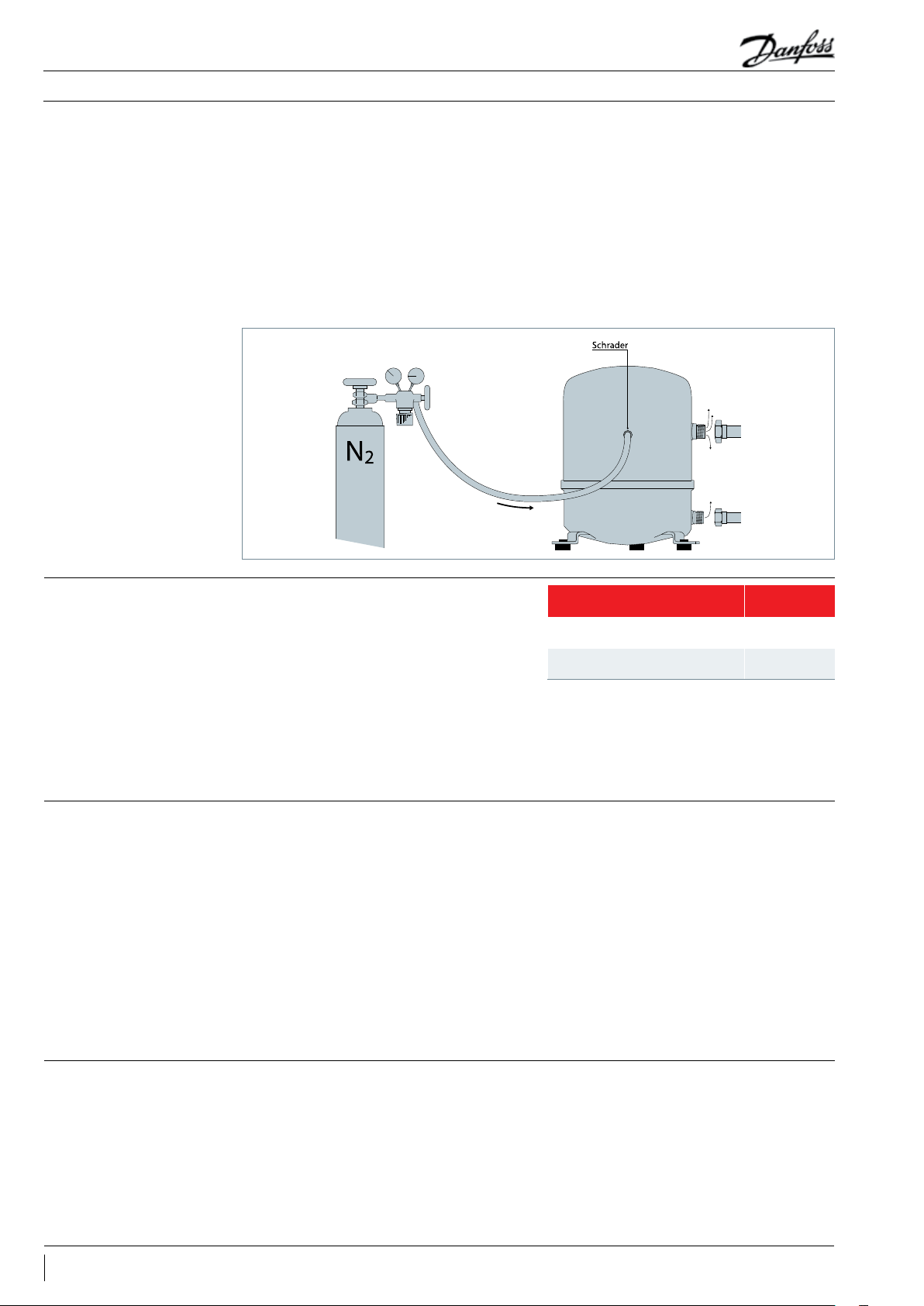
Application Guidelines
Installation and service
System pressure test
In this situation nitrogen or CO
must be purged
2
through the compressor via the schrader valve to
prevent air and moisture ingress. Purging must
start when the caps are removed and proceeded
during the brazing process.
When rotolock valves are used on the
compressor, they shall be closed immediately
after mounting, thus keeping the compressor
isolated from atmosphere or from a not yet
dehydrated system.
It is recommended that an inert gas such as
nitrogen be used for pressure testing. Dry air
may also be used but care should be taken
since it can form an inflammable mixture with
the compressor oil. When performing a system
pressure test, the maximum allowed pressure
for the different components should not be
exceeded.
For MT/MTZ compressors the maximum test
pressures are shown in the table beside.
Note: When the compressor is built into a ”pack”
or “rack” configuration which is not installed
immediately on its final location, a vacuum pulldown and moisture removal must be performed
to this pack (rack) as if it were a complete system
(see below). The pack must be charged with
nitrogen or CO
and open tubes must be blocked
2
with caps or plugs.
1-2-4 cylinder
compressors
Maximum compressor test
pressure, low side
Maximum compressor test
pressure, high side
25 bar(g)
30 bar(g)
Do not exceed 30 bar pressure difference
between high pressure side and low pressure
side of the compressor because this will open the
internal compressor relief valve.
Leak detection
Vacuum pull-down moisture removal
Whenever possible (if valves are present) the
compressor must be kept isolated from the
system. Perform a leak detection using the final
refrigerant. Pressurise with nitrogen or another
neutral gas and use a leak detector for the
applied refrigerant. Any spectrometric detection
system using helium can also be applied.
Eventual leaks shall be repaired respecting
the instructions written above. It is not
recommended to use other gasses such as
oxygen, dry air or acetylene as these gasses can
form an inflammable mixture. Never use CFC
Moisture obstructs the proper functioning of the
compressor and the refrigeration system.
Air and moisture reduce service life and increase
condensing pressure, and cause excessively high
discharge temperatures, which can destroy the
or HCFC refrigerants for leak detection of HFC
systems.
Note 1: Leak detection with refrigerant may
not be allowed in some countries. Check local
regulations.
Note 2: Leak detecting additives shall not be
used as they may affect the lubricant properties.
Warranty may be voided if leak detecting
additives have been used.
lubricating properties of the oil. Air and moisture
also increase the risk of acid formation, giving
rise to copper platting. All these phenomena
can cause mechanical and electrical compressor
failure.
34 AB196386425654en-021502
Page 35
Application Guidelines
Installation and service
Start-up
To eliminate these factors, a vacuum pulldown according to the following procedure is
recommended:
Whenever possible (if valves are present)
the compressor must be kept isolated from the
system.
After the leak detection, the system must be
pulled-down under a vacuum of 500 microns
(0.67 mbar). A two stage vacuum pump shall be
used with a capacity appropriate to the system
volume. It is recommended to use connection
lines with a large diameter and to connect these
to the service valves and not to the schrader
connection to avoid too high pressure losses.
When the vacuum level of 500 micron is
reached, the system must be isolated from the
vacuum pump. Wait 30 minutes during which
the system pressure should not rise. When the
pressure rapidly increases, the system is not leak
tight.
Before initial start-up or after a prolonged shut
down period, energise the crankcase heater
(if fitted) 12 hours prior to start-up, or turn on
A new leak detection must be performed and
the vacuum pull-down procedure should be
restarted from step 1. When the pressure slowly
increases, this indicates the presence of moisture.
In this case step 2 and 3 should be repeated.
Connect the compressor to the system by
opening the valves. Repeat step 2 and 3.
Break the vacuum with nitrogen or the final
refrigerant.
Repeat step 2 and 3 on the total system.
At commissioning, system moisture content may
be up to 100 ppm. During operation the filter
drier must reduce this to a level < 20 ppm.
Do not use a megohmmeter or apply power
to the compressor while it is under vacuum, as
this may cause motor winding damage.
R
Never run the compressor under vacuum
as it may cause compressor motor burn-out.
power for single phase compressors with trickle
circuit.
Refrigerant charging
Oil charge and oil level
Suction gas superheat
R
Zeotropic and «near-azeotropic»
refrigerant mixtures such as R404A, R407A/C/F,
R448A, R449A, R454C and R455A must always
be charged in the liquid phase. For the initial
charge, the compressor must not run and service
valves must be closed. Charge refrigerant as
close as possible to the nominal system charge
before starting the compressor. Then slowly
add refrigerant in the liquid phase, on the low
pressure side as far away as possible from the
running compressor.
The oil charge must be checked before
commissioning (1/4 to 3/4 of the oil sight glass).
Check the oil level again after a minimum of 2
hours operation at nominal conditions. In most
installations the initial compressor oil charge
will be sufficient. In installations with line runs
exceeding 20 m or with many oil traps or an
oil separator, additional oil may be required.
Normally the quantity of oil added should be
no more than 2% of the total refrigerant charge
(this percentage does not take into account oil
The optimum suction gas superheat is 10K. A
lower superheat value will contribute to better
system performance (higher mass flow and
more efficient use of evaporator surface). Low
super heat values however increase the risk of
unwanted liquid floodback to the compressor.
For very low superheat values an electronically
controlled expansion valve is recommended.
The refrigerant charge quantity must be suitable
for both winter and summer operation. Refer
also to section “Protection against flooded starts
and liquid floodback” for information about
refrigerant charge limits.
R
when a liquid line solenoid valve is used,
the vacuum in the low pressure side must be
broken before applying power to the system.
contained in accessories such as oil separators
or oil traps). If this amount has already been
added and the oil level in the compressor keeps
decreasing, the oil return in the installation is
insufficient. Refer also to section "Piping design".
In installations where slow oil return is likely such
as in multiple evaporator or multiple condenser
installations, an oil separator is recommended.
Refer to the table section “Refrigerant and
lubricants” to select the correct oil.
The maximum allowable superheat is about 30
K. Higher values can be accepted but in these
cases, tests have to be performed to check that
the maximum discharge temperature of 130°C
will not be exceeded. Note that high superheat
values decrease the compressor application
envelope and system performance.
35AB196386425654en-021502
Page 36
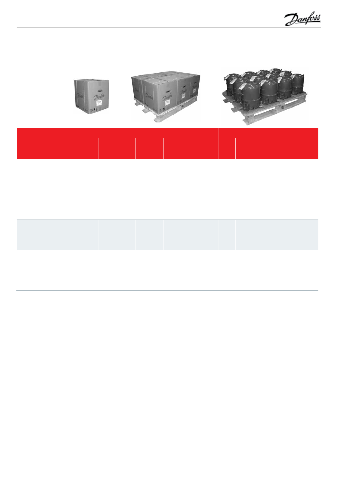
Application Guidelines
Ordering information and packaging
Packaging
Single pack Multipack Industrial pack
Model code 4
MT/MTZ 018
MT/MTZ 022 23 197 278
MT/MTZ 028 25 213 302
MT/MTZ 032 26 221 314
1 cylinder
MT/MTZ 036 27 229 326
Dimensions
(mm)
l: 330
w: 295
h: 385
Gross
weight
(kg)
23
Nbr
8
Dimensions
(mm)
l: 1150
w: 800
h: 510
Gross
weight
(kg)
197
Static
stacking
4 12
Nbr
Dimensions
(mm)
l: 1150
w: 800
h: 500
Gross
weight
(kg)
278
Static
stacking
4
MT/MTZ 040 27 229 326
MT/MTZ 044-050
2 cylinders
MT/MTZ 072-080 43 268 260
MT/MTZ 100
MT/MTZ 125 73 303 399
MT/MTZ 144 76 315 417
4 cylinders
MT/MTZ 160 76 315 417
Single pack: One compressor in a cardboard box.
Multipack: A full pallet of compressors, each individually packed in a cardboard box. Mainly dedicated to wholesalers and Danfoss
Industrial pack: A full pallet of unpacked compressors. Mainly dedicated to OEM customers.
Nbr: Number of compressor in a pack
In some publications this packaging may be indicated as individual packaging.
All single pack of 4 cylinder are shipped with a small 1/4 euro pallet (570 x 400 x 117 mm) under the individual box.
distribution centres.
In some publications this packaging may be indicated as ‘Multiple packaging.
l: 395
w: 365
h: 455
l: 470
w: 400
h: 650
39
70
l: 1150
6
w: 800
h: 600
l: 1150
4
w: 800
h: 800
244
291
4 6
4 6
l: 1150
236
w: 800
h: 600
381
l: 1150
w: 800
h: 710
4MT/MTZ 056-064 41 256 248
4
36 AB196386425654en-021502
Page 37

Application Guidelines
Ordering information and packaging
MT compressors in industrial pack - R22
Code no.
Compressor
model
MT018 MT18-1VM MT18-3VM MT18-4VM MT18-5VM -
MT022 MT22-1VM MT22-3VM MT22-4VM MT22-5VM MT22-9VM
MT028 MT28-1VM MT28-3VM MT28-4VM MT28-5VM MT28-9VM
MT032 MT 32-1VM MT32-3VM MT32- 4VM MT32-5VM MT32-9VM
MT036 MT36-1VM MT36-3VM MT36-4VM MT36-5VM MT36-9VM
MT040 MT4 0-1VM MT4 0-3VM MT40 -4VM - -
MT044 MT4 4-1VM MT4 4-3VM MT4 4- 4VM - MT4 4-9VM
MT050 MT50-1VM MT50-3VM MT50-4VM - MT50-9VM
MT056 MT56-1VM MT56-3VM MT56-4VM - MT56-9VM
MT064 MT64-1VM MT64-3VM MT64- 4VM - MT64-9VM
MT072 - MT72-3VM MT72-4VM - MT72-9VM
MT080 - MT80-3VM MT80-4VM - MT80-9VM
MT100 - MT100-3VM MT100-4VM - MT100 -9VM
MT 125 - MT125-3VM MT125- 4VM - MT125 -9VM
MT144 - MT144-3VM MT144 -4VM - MT14 4-9VM
1 3 4 5 9
208-230/1/60 200-230/3/60
460/3/60
400/3/50
230/1/50 380/3/60
MT160 - MT160 -3VM MT160-4VM - MT160-9VM
VM = Compressor, threaded oil sight glass, 3/8" oil equalisation connection
37AB196386425654en-021502
Page 38

Application Guidelines
Ordering information and packaging
MT compressors in single pack - R22
Code no.
Compressor
model
MT018 MT18-1V I MT18-3VI MT18-4VI MT18-5VI - - -
MT022 MT 22-1VI MT22-3VI MT22-4VI MT22-5VI MT22-6VI - MT22-9VI
MT028 MT28 -1VI MT28-3VI MT28-4VI MT28-5VI MT28-6VI - MT28-9VI
MT032 MT32-1VI MT32-3VI MT32-4VI MT32-5VI MT32-6VI - -
MT036 MT36-1VI MT36-3VI MT36-4VI MT36-5VI MT36-6VI - MT36-9VI
MT040 MT40 -1VI MT4 0-3VI MT40 -4V I - MT40 -6VI - -
MT044 - MT44-3V I M T44-4VI - - - M T44-9VI
MT050 MT50 -1VI MT50-3VI MT50-4VI - MT50-6VI - MT50-9VI
MT056 MT56 -1VI MT56-3VI MT56-4VI - MT56-6VI MT56-7VI MT56-9VI
MT064 MT64 -1VI MT64 -3VI MT64-4VI - MT64-6VI - MT64-9VI
1 3 4 5 6 7 9
208-230/1/60 200-230/3/60
460/3/60
400/3/50
230/1/50 230/3/50
575/3/60
500/3/50
380/3/60
MT072 - MT72-3VI MT72-4VI - - - MT72-9VI
MT080 - MT80 -3VI MT80-4VI - MT80-6VI - MT80-9VI
MT100 - MT100-3VI MT100-4VI - MT100-6VI MT100 -7VI MT100 -9VI
MT 125 - MT125-3VI M T125- 4VI - MT125-6VI MT125-7VI M T125 -9V I
MT144 - MT144-3VI MT144- 4VI - - MT144-7VI M T144-9VI
MT160 - MT160-3VI MT160-4VI - MT160 -6V I MT160 -7VI MT160 -9VI
VI = Single compressor, threaded oil sight glass, 3/8" oil equalisation connection
38 AB196386425654en-021502
Page 39

Application Guidelines
Ordering information and packaging
MTZ compressors in industrial pack
R404A / R507A / R134a / R407A / C / F / R448A / R449A / R452A / R454C* / R455A* / R513A
Code no.
Compressor
model
MTZ018 MTZ18 -1VM MTZ18-3VM MT Z18-4VM* MTZ18-5VM* -
MTZ022 MT Z22-1VM MTZ22-3VM MTZ22-4VM* MTZ22-5VM* MTZ22-9VM
MTZ028 MTZ28-1VM MTZ28-3VM MTZ28-4VM* MTZ28-5VM* MTZ28-9VM
MTZ032 MTZ32-1VM MTZ32-3VM MTZ32-4VM* MTZ32-5VM* MTZ32-9VM
MTZ036 MTZ36-1VM MTZ36-3VM MTZ36-4VM* MTZ36-5VM* MTZ36-9VM
MTZ040 MTZ40-1VM MTZ40-3VM MTZ40-4VM* - -
MTZ044 MTZ44 -1VM MTZ44-3VM MTZ44-4VM - MTZ44-9VM
MTZ050 MTZ50 -1VM MTZ50-3VM MTZ50-4VM - MTZ50-9VM
MTZ056 MTZ56-1VM MTZ56-3VM MTZ56-4VM - MTZ56-9VM
MTZ064 MTZ64 -1VM MTZ64-3VM MTZ64-4VM - MTZ64-9VM
MTZ072 - MTZ72-3VM MTZ72-4VM - MTZ72-9VM
MTZ080 - MTZ80-3VM MTZ80-4VM - MTZ80-9VM
MTZ100 - MTZ10 0-3VM MTZ100 -4VM - MTZ100-9VM
MTZ125 - M TZ125 -3VM MTZ125-4VM - MT Z125 -9 VM
MTZ144 - MTZ14 4-3VM MTZ144- 4VM - MTZ144- 9VM
MTZ160 - MTZ160-3VM MTZ160-4VM - MTZ160-9VM
1 3 4 5 9
208-230/1/60 200-230/3/60
460/3/60
400/3/50
230/1/50 380/3/60
VM = Compressor, threaded oil sight glass, 3/8" oil equalisation connection
* Qualifed with R454C / R455A.
39AB196386425654en-021502
Page 40

Application Guidelines
Ordering information and packaging
MTZ compressors in single pack
R404A/R507A / R134a / R407A/C/F / R448A/R449A / R452A / R454C* / R455A* / R513A
Code no.
Compressor
model
MTZ018 MTZ18 -1VI MTZ18-3VI MTZ18-4VI* MTZ18-5VI* - - -
MTZ022 MTZ22-1VI MTZ22-3VI MTZ22-4VI* MTZ22-5VI* MTZ22-6VI - MTZ22-9VI
MTZ028 MT Z28 -1VI MTZ28-3VI MTZ28-4VI* MTZ28-5VI* MTZ28-6VI - MTZ28-9VI
MTZ032 MTZ32-1VI MTZ32-3VI MTZ32-4VI* MTZ32-5VI* MTZ32-6VI MTZ32-7 VI MTZ32-9VI
MTZ036 MT Z36-1V I MTZ36-3VI MTZ36-4VI* MTZ36-5VI* MTZ36-6VI MTZ36 -7VI MTZ36-9VI
MTZ040 MTZ40-1VI MTZ40-3VI MTZ40-4VI* - MTZ40-6VI - -
MTZ044 MT Z44-1V I MTZ44-3VI MTZ44-4VI - MTZ44-6VI MTZ4 4-7VI MTZ44-9VI
MTZ050 MT Z50-1V I MTZ50-3VI MTZ50-4VI - MTZ50-6VI MT Z50-7VI MTZ50-9VI
1 3 4 5 6 7 9
208-230/1/60 200-230/3/6 0
460/3/60
400/3/50
230/1/5 0 230/3/50
575/3/60
500/3/50
380/3/60
MTZ056 MT Z56-1V I MTZ56-3VI MTZ56-4VI - MTZ56-6VI MTZ56-7VI MTZ56-9VI
MTZ064 MT Z64-1V I MTZ64-3VI MTZ64-4VI - MTZ64-6VI - MTZ64-9VI
MTZ072 - MTZ72-3VI MTZ72-4VI - MTZ72-6VI - MTZ72-9VI
MTZ080 - MTZ80-3VI MTZ80-4VI - MTZ80-6VI - MTZ80-9VI
MTZ100 - MTZ100-3VI MTZ100-4VI - MTZ100-6VI MTZ10 0-7VI MTZ100-9VI
MTZ125 - MTZ125-3V I MTZ125-4VI - MTZ125- 6VI MTZ12 5-7VI MTZ125-9VI
MTZ144 - MTZ144-3VI MTZ14 4- 4VI - - MT Z144-7VI MTZ14 4- 9VI
MTZ160 - MTZ160-3VI MTZ160-4VI - MTZ160- 6VI MTZ160-7VI MTZ160 -9VI
VI = Single compressor, threaded oil sight glass, 3/8" oil equalisation connection
* Qualifed with R454C / R455A.
40 AB196386425654en-021502
Page 41

Application Guidelines
Current version updates Previous version updates
Updates
• Page 22: MCC value for MTZ56-4 was changed
• Page 32: sound data for MTZ56-4 was changed
• Page 12: Nominal performance data for R454C is added
• Page 15: Operating envelope for R454C is added
• Page 25: Refrigerants and lubricants - R454C with POE oil is
added
• Page 27: Refrigerants and lubricants - R454C is added
• Page 29: Pressures for R454C are added
• Page 32: Sound data for R454C is added
• Adding R455A with R454C for all on this page
41AB196386425654en-021502
Page 42

Danfoss Cooling
Danfoss Inverter Scrolls
is a worldwide manufacturer of compressors and condensing units for refrigeration and HVAC applications. With a wide range
of high quality and innovative products we help your company to find the best possible energy efficient solution that respects
the environment and reduces total life cycle costs.
We have 40 years of experience within the development of hermetic compressors which has brought us amongst the global
leaders in our business, and positioned us as distinct variable speed technology specialists. Today we operate from engineering
and manufacturing facilities spanning across three continents.
Danfoss Turbocor Compressors
Danfoss Scrolls
Danfoss Optyma™ Condensing Units
Danfoss Maneurop Reciprocating Compressors
Danfoss Light Commercial Refrigeration
Compressors
Our products can be found in a variety of applications such as rooftops, chillers, residential air conditioners,
heatpumps, coldrooms, supermarkets, milk tank cooling and industrial cooling processes.
AB196386425654en-021502 © Danfoss | Climate Solutions | 2021.11
 Loading...