

Page 1
Managing Harmonic Distortion with Quasi 12-pulse
■■
■ Conventional Reduction Techniques
■■
For many years, the most commonly used method for
reducing harmonic distortion caused by Variable Frequency Drives in electrical systems has been to add
AC line reactors at the drives' input terminals. This reduces the harmonic distortion to a level which will be
sufficient in most installations. There is however a
practical limit to the size of the reactors which can be
installed and therefore also to the possible reduction
in harmonics which can be obtained by using this
technique.
The reason is that the drives' ability to supply full output torque is reduced as a result of voltage drop
across the reactors. The only way to compensate
for this is to increase the current supplied to the motor. This means that the motors must be able to
manage higher currents at the same torque requirement. Larger drives may also be required. However,
this causes a waste of resources as a result of increased generation of heat. This must be considered
when dimensioning the system in order to avoid overheating.
Managing Harmonic Distortion with Quasi 12-pulse
Another well-known technique is to implement DC
reactors in the intermediate circuit. This is however
not very practical if large reactors are needed, since
these reactors would produce a lot of heat in the
drives and reduce the drives' efficiency.
In order to avoid the unfortunate side effects of AC
or DC reactors in installations where high requirements to the reduction of harmonic distortion exist,
it has become the norm in certain markets to utilise
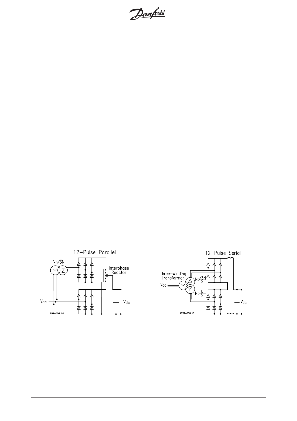
12 pulse drives. These drives consist of two 6 pulse
rectifiers and either a phase shifting transformer in
front of one of the rectifiers or a three winding transformer in front of the combined rectifier. See Figure
1 for schematic.
Figure 1: 12 Pulse Drives with Rectifiers in Parallel and in Series
This design provides excellent harmonic performance. The 5
celled almost completely. The two rectifiers and
either a phase shifting transformer and an interface
reactor (left solution in Figure 1) or a three winding
transformer
th
and 7th harmonic currents are can-
(right solution in Figure 1) makes this solution at least
50% more expensive than a standard drive with
built-in DC reactors. Therefore a more wide spread
use of it would mean a drastic increase in the cost per
drive installed.
MN.90.J2.02 - VLT is a registered Danfoss trademark
Page 2
■■
■ The alternative solution
■■
Managing Harmonic Distortion with Quasi 12-pulse
An alternative solution would be to use phase shifting transformers in front of 50% of the drive load and
then leave the other drives connected to the normal
mains.
The cost of this solution is only about 16% higher
than the cost of a standard Danfoss VLT frequency
converter. Since a transformer is only required on
every second drive, the total impact on the frequency converter cost is reduced to 8%. This is,
however, compared to a standard solution without
any additional harmonic filtering.
When considering this type of harmonic filtering, a
comparison with a solution where a 5% AC line reactor is used would be more realistic. This will not
nearly give the performance of the quasi 12 pulse,
but it is the largest AC line reactor which can be recommended installed in front of a Danfoss VLT Frequency Converter. A 5% AC line reactor will increase
Managing Harmnic Distortion with Quasi 12-pulse
the drive cost by approx. 2%. This means that the actual additional cost to a project would come to
approx. 6%.
The argument against this solution compared to a
true 12-pulse solution is that the balance of the
load is important to the performance, because the
improved performance is a result of the cancellation
of the 5
phase shift.
When the load is not balanced, the harmonics on
the drives with high load are not cancelled. This is
because the whole basis for the cancellation is that
the current vectors are of equal amplitude and that
the angle between them is 180°. The angle is maintained by the phase shifting transformer, but the
amplitude varies as the load decreases. When the
load only decreases on one of the drives, the length
of the vectors becomes unequal and full cancellation
is not achieved.
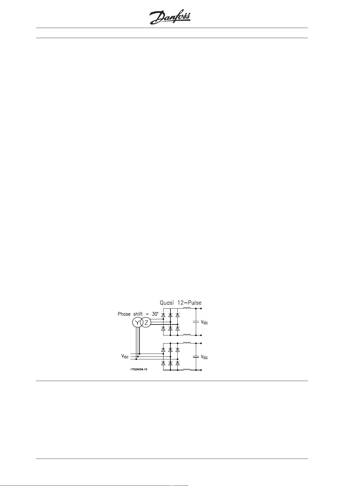
Figure 2 shows the system configuration for an installation using quasi 12-pulse. Please notice that standard 6 pulse frequency converters are used and that
the estimated load on each drive group should be as
close to equal as possible to achieve the best effect.
See the following sections to get a general impression
of the performance of quasi 12 pulse on the 2 drive
groups.
th
and 7th harmonic current due to the 30°
Figure 2: System Configuration for Quasi 12 Pulse
■■
■ Simulation of the Effects of Varying Load
■■
The research at Danfoss Drives into the significance
of load variations has revealed that there is a significant advantage to be obtained by using quasi 12
Pulse as long as all drives are above 20% load.
Whether or not the load is the same is less important.
Table 1 and Figure 3 on the following page show the
results of a simulation of the Total Harmonic Current
Distortion (THCD) as a function of the load on two
drive groups.
MN.90.J2.02 - VLT is a registered Danfoss trademark
Page 3

Managing Harmonic Distortion with Quasi 12-pulse
Table 1: Total Harmonic Current Distortion as a Function of Varying Load
Drive group 1
Load 100% 80% 60% 40% 20% 0%
100% 10.7% 11.6% 13.4% 16.7% 22.3% 37.4%
80% 10.6% 11.1% 12.4% 15.5% 21.8% 41.3%
60% 11.7% 11.5% 12.1% 14.8% 21.9% 48.6%
40% 13.9% 13.2% 13.0% 14.8% 22.8% 63.6%
20% 18.4% 17.5% 16.1% 14.7% 16.6% 88.5%
Drive group 2
0% 32.2% 34.7% 38.9% 47.0% 74.5% (100.0%)
Figure 3: Total Harmonic Current Distortion as a Function of Varying Load
100,0%
Managing Harmonic Distortion with Quasi 12-pulse
80,0%
60,0%
20%
40,0%
20,0%
0,0%
0%
Drive group 2
20%
60%
100%
100%
80%
60%
40%
Drive group 1
The impact on the Total Harmonic Voltage Distortion (THVD) in the system was also simulated under the same
conditions and the results are shown below in Table 2 and Figure 4.
Table 2: Total Harmonic Voltage Distortion as a Function of Varying Load
Drive group 1
Load 100% 80% 60% 40% 20% 0%
100% 2.3% 2.2% 2.3% 2.1% 2.2% 2.4%
80% 2.1% 1.9% 1.8% 1.7% 1.7% 2.0%
60% 2.0% 1.8% 1.8% 1.7% 1.7% 1.9%
40% 1.6% 1.4% 1.3% 1.2% 1.1% 1.4%
20% 1.5% 1.2% 1.1% 0.8% 0.7% 0.9%
Drive group 2
0% 1.7% 1.4% 1.3% 1.0% 0.7% 0.0%
MN.90.J2.02 - VLT is a registered Danfoss trademark
!
Page 4

Figure 4: Total Harmonic Voltage Distortion as a Function of Varying Load
00%
60%
Drive group 2
■ ■
■ Comments to the Simulation Results
■ ■
20%
Table 2 and Figure 4 show that the Total Harmonic
Voltage Distortion level never exceeds 5% when quasi
Managing Harmonic Distortion with Quasi 12-pulse
12 pulse is used in combination with a Danfoss drive.
This will be true in most systems as long as the transformer's drive load (in kVA) does not exceed 90% of
transformer's nominal power.
Furthermore the Total Harmonic Current Distortion will
never exceed 25% under the same conditions provided that there is a load balance between drives on
the phase shifting transformer and the drives connected directly to the main transformer which is always 1:5 or better. This does not mean that the
load on each individual drive cannot go below 20%,
only that if 50% of the drives are at no load, the
other 50% must be at least at 40% load for each of
the two drive groups.
It is a precondition for this solution to be valid that
the nominal drive load can be distributed equally between the phase shifting transformer and the drive
group directly connected to the main transformer.
Alternatively, a phase shifting transformer is connected to every second drive in the installation.
More accurate information about the voltage distortion
generated in a specific system where this solution is
used, requires a detailed simulation including the
Managing Harmonic Distortion with Quasi 12-pulse
2,5%
2,0%
1,5%
%
th
and 7th harmonics gener-
20%
40%
0%
Drive group 1
1,0%
0,5%
0,0%
80%
60%
100%
background distortion and single-phase non-linear
loads.
Knowledge about the single-phase non-linear loads
is more critical in a 12-pulse installation, since there
is no cancellation of the 5
ated by these loads. This applies to installations
where the drives are equipped with 12-pulse rectifiers as well as in installations where a quasi 12-pulse
installation is made.
Single phase non-linear loads could be equipment
such as computers, Xerox machines, faxes, fluorescent light, radios, televisions and small air-conditioners all of which use a rectifier to generate a DC
voltage supply. Some of these machines use active
filters which do not produce harmonics, but this is
not the norm yet. Also fluorescent light can have
balanced or electronic ballasts which do not produce harmonic distortion.
In installations where standard 6-pulse rectifiers are
used, the 5th and 7th harmonics generated are
counterphased to those of the single-phase loads and
background distortion. Information about the singlephase loads and background distortion is therefore
not as critical in a 6-pulse installation.
■ ■
■ Conclusion
■ ■
In installations where it is very important to achieve
low voltage distortion, quasi 12 pulse will give the
optimum results at the lowest cost.
"
MN.90.J2.02 - VLT is a registered Danfoss trademark
 Loading...