

Page 1

District heating application guide
Making applications
future proof all our
knowledge – is now yours
+30
years of experience
in district heating
applications, with
more than 5 million
installations worldwide.
www.districtenergy.danfoss.com
Page 2

Structure
Recommended solution for heating systems / New construction 4
Recommended solution for heating systems / Renovation 6
1 Introduction 8
1.1 District Heating nets in China Yesterday, Today and Tomorrow 10
1.2 Common problems of the current District Heating systems in China and their causes 11
1.2.1 Heat losses in networks 11
1.2.2 Hydraulically unbalanced networks 12
1.2.3 Over specied pumps 14
1.2.4 Lack of centralized hot water treatment for DHW systems 14
1.2.5 General energy ineciency of the heat supply system 15
2 Connection to the grid 16
2.1 Central substation equipped by weather compensator, no controls in the building – direct connection of the buildings 16
2.2 Central substation equipped by weather compensator. Few buildings had Mixing units or substation at the entrance 18
2.3 Central Substations with mixing loops at each building or every connection 19
2.4 Substations in each building 20
2.5 Flat stations in each at for the same district 25
2.6 Conclusion 22
3 Direct connection of Heating system (connected via Central substations) 24
3.1 Mixing loop with Weather compensation and Combination valves for the Heating systems 21
3.2 Mixing-loop for Heating system, recommended than dP less than 2 bar 26
3.3 Mixing loop with 3-way valves to be used if the temperature in primary and secondary systems are equal 28
3.4 Mixing loop for Heating system with Weather compensation, Motorized Control Valves and Manual Balancing valves 30
3.5 Mixing loop for Heating system with Weather compensation and motorized control valves for the systems with
T in secondary side equal to T on primary side 32
2
Page 3

4 Indirect connection of Heating system (Direct connection to the primary circuit) 34
4.1 Indirect connection of Heating system with DPC and MCV. DPC play also role of Flow limiter 34
4.2 Indirect connection of Heating system with DPCQ and MCV. DPCQ secure automatic ow limitation 36
4.3 Indirect connection of HE system with PIBCV 38
4.4 Indirect connection of HE system with MBV and MCV 40
4.5 Indirect connection of heating system with MCV only 42
5 Indirect connection of Heating and Domestic Hot water systems – directly to the primary side 44
5.1 Indirect connection of HE and DHW with common DPC 44
5.2 Indirect connection of HE and DHW with DPC on each circuit 46
5.3 Indirect connection of Heating and DHW system with DPCQ on each circuit 48
5.4 Indirect connection of HE and DHW systems with PIBCV used as control valve 50
5.5 Indirect connection HE and DHW systems with no DPC 52
5.6 Heating System connected thru Central substation via DPC on the entrance 54
6 Overall classication of Direct and Indirect Heating and Domestic Hot water 56
6.1 Direct heating system connection 56
6.2 Direct heating system connection 57
6.3 Domestic Hot Water Systems / Indirect DHW system connection 60
7 Product overview 62
7.1 Weather compensators - WC 62
7.2 Motorized Control Valves - MCV 62
7.3 Actuators for MCV and PICV 63
7.4 Pressure Independent Control Valves - PICV 63
7.5 Dierential Pressure (and Flow) Controllers - DPC (DPCQ) 64
7.6 Steel manual balancing valve and Ball valves 64
7.7 Temperature controllers 65
7.8 Energy meters 65
3
Page 4
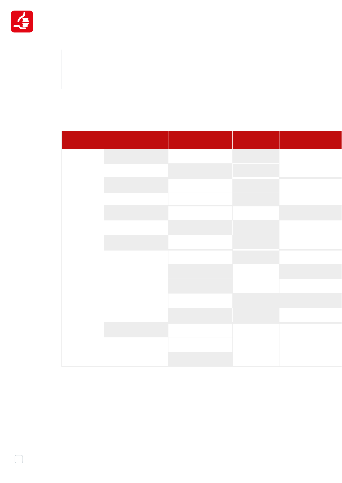
RECOMMENDED SOLUTION
Recommended solution for heating systems
NEW CONSTRUCTION
for heating systems
Source Distrubution/
transporatation
Distribution station *****
Distribution station Mixing loop FH + RT ****
Distribution station DPC Two pipe horizon + TRV ***
Heating
source
Distribution station
New construction:
Entrance of Building
Substation
Substation
Substation DPC Two pipe raise + TRV ****
Substation PIBCV Horizon / FH ***
Mixing loop PIBCV
DPC ** Up to 6 oors
Raiser Entrance of
Apartment
Flat station
DPC
DPC
MBV
PIBCV Horizon **
Substation
Distribution station Mixing loop FH **
4
DPC ON/OFF CV
Page 5
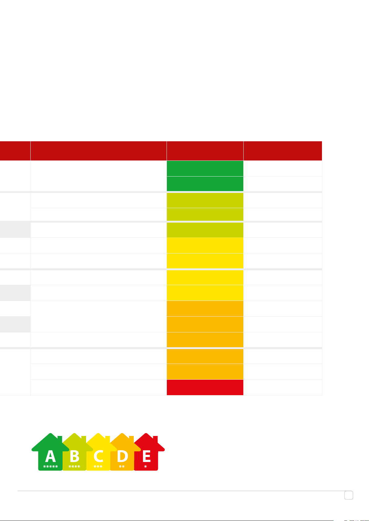
In the Apartment Recommend index Note
*****
Two pipe horizon + TRV / FH + RT
Two pipe horizon + TRV / FH + RT ****
FH ***
Two pipe raise + TRV ***
** More than 6 oors
Two pipe horizon + TRV / FH + RT
Horizon / FH **
Horizon *
Recommend index
5
Page 6
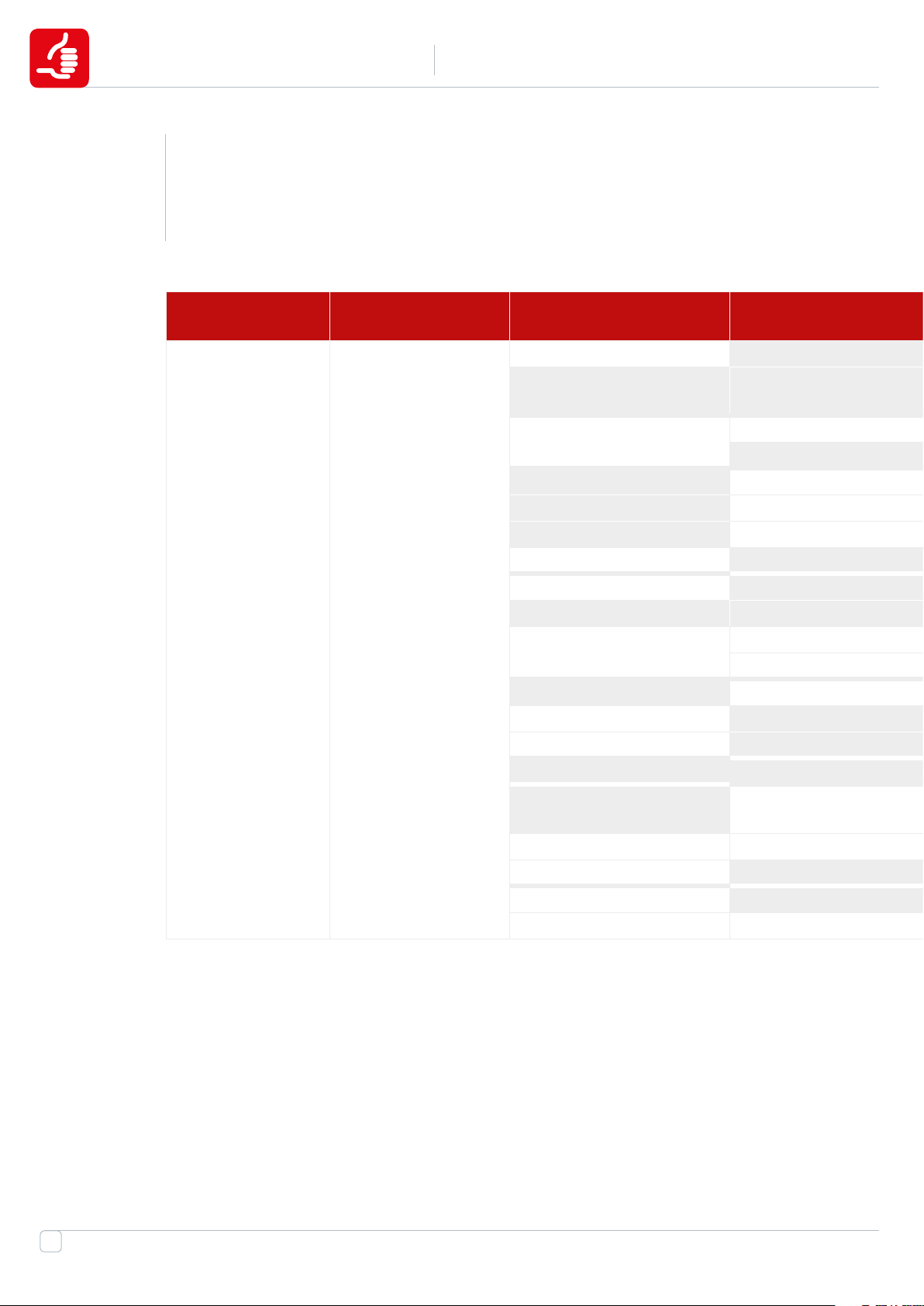
RECOMMENDED SOLUTION
Recommended solution for heating systems
RENOVATION
for heating systems
Source Distribution and
Transportation
CHP or Boiler
house
Distribution station
Entrance of Building Raiser Entrance of
Mixing loop
DPC
Mixing loop
DPC Two pipe raise + TRV ***
PIBCV+T One pipe raise + TRV ***
DPC MBV
DPC ** Up to 6 oors
Mixing loop MBV One pipe horizon + TRV **
DPC
Mixing loop
Flat station
DPC **
Mixing loop **
DPC
DPC ON/OFF CV * Up to 6 oors
Mixing loop *
Mixing loop Riser system *
Flat station MBV One pipe raise + TRV *
6
Page 7
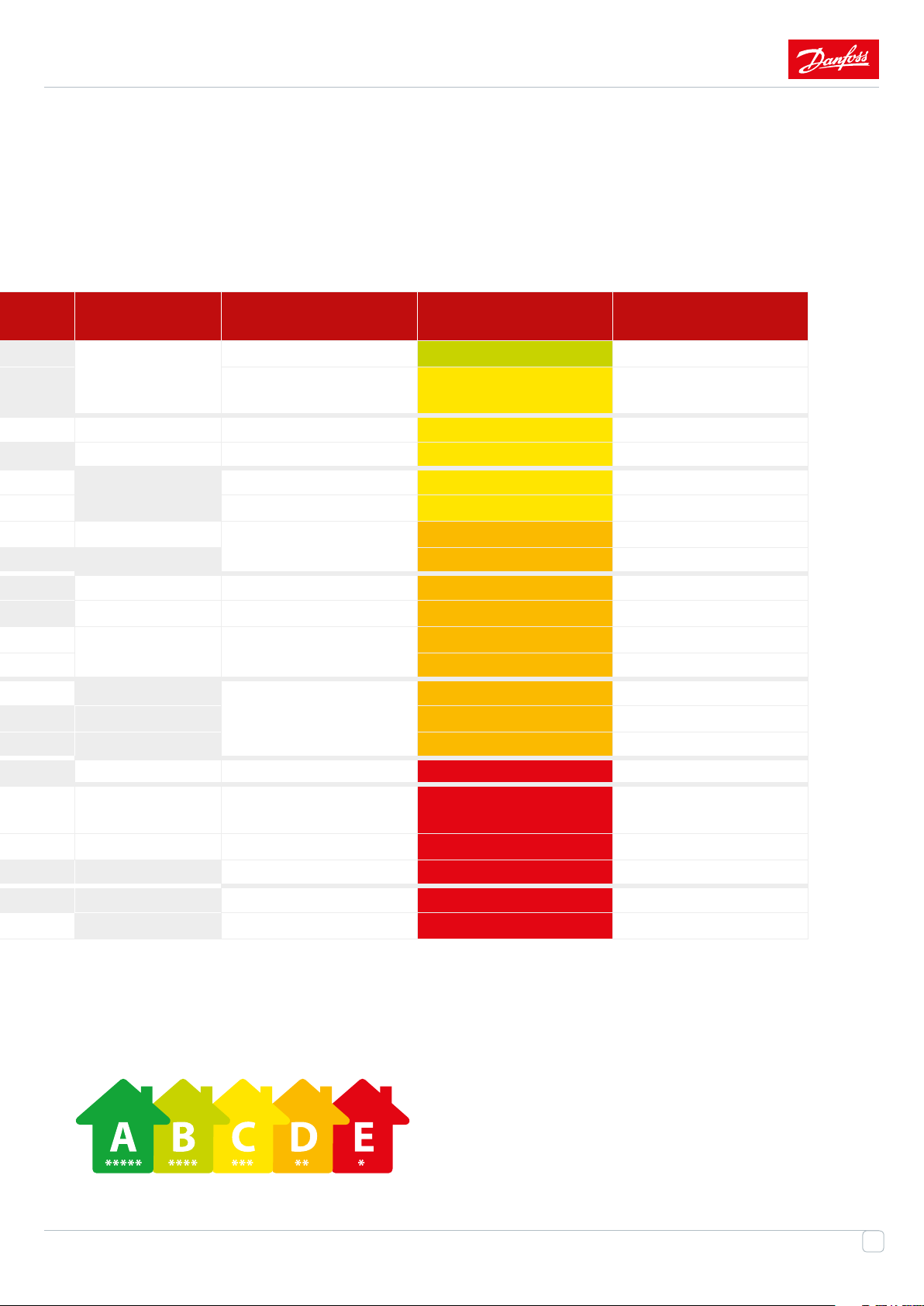
In the Apartment Recommend index Note
Apartment
FH + RT ****
DPC
Two pipe horizon + TRV
/ FH + RT
***
MBV FH + RT ***
PIBCV FH ***
Two pipe horizon + TRV
** More than 6 oors
/ FH + RT
PIBCV Horizon / FH **
** More than 6 oors
ON/OFF CV FH
** Up to 6 oors
**
One pipe raise + TRV
FL One pipe horizon + TRV *
ON/OFF CV with
preset
Horizon / FH * More than 6 oors
Recommend index
7
Page 8
1
Introduction
With every day it becomes more and more obvious that energy eciency is one of the main trends in
the 21st century economic development. All branches of modern industry, from microelectronics to
heavy engineering, are striving to reduce energy losses. Today there is no other way: we may just go
forward or step aside of the progress.
This may seem incredible, but it is our unbounded household power inputs that cause the global
warming. In Europe, about 40% of fuel-energy resources are consumed by communal consumers,
while transport and industry consume 32% and 28% respectively. Notwithstanding the fact that
energy saving is an integral part of public policy of Western countries for many years. First of all,
this was favoured by the energy crisis which took place in 1970s and signicantly aected those
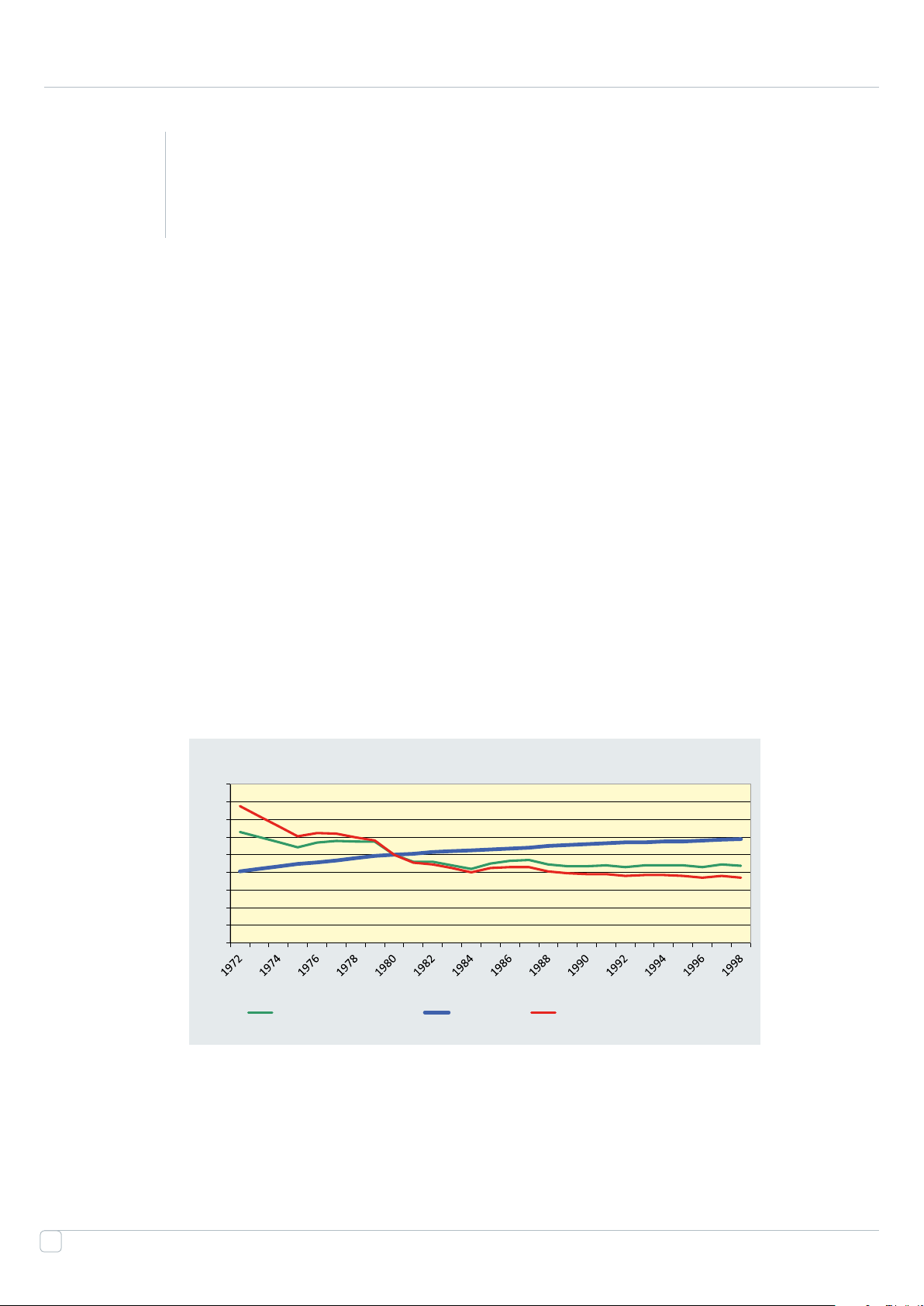
countries. Last year’s many of developed countries have achieved signicant results in this eld. In 25
years, they turned from consumers into suppliers of energy resources, rising to the rst places in the
world in energy eciency.
Index: 1980 = 100
180
160
140
120
100
80
60
40
20
0
Total energy consumption Heated area Energy consumption per m2
Figure 1:
8
Page 9

Realizing that in future, high energy costs will be necessary to maintain high rates of growth, the
China Government has begun to implement a large-scale plan of radical increase of energy eciency
and decrease of fast-growing demand for coal from energy-consuming industries. For each level
of the government administration a target for decrease of energy consumption, which must be
achieved, is set. In addition to that, the Government has begun to implement a "large-scale program
of closing of ineective companies". Eorts, which China applies, striving to raise its energy ecien-
cy, are probably the most resolute ones among those that have been ever applied in this eld by any
country. They will be discussed for years. But in spite of this trend there are several other problems,
for example, in heat-power engineering, particularly concerning heat distribution. Unfortunately,
the current condition of heat networks is far from the ideal, while it is not possible to carry out the
necessary replacements instantly. In this book, the main issues will be discussed and solutions,
related to Danfoss, its equipment and experience, will be proposed.
9
Page 10
1.1
District Heating nets in China
Yesterday, Today and Tomorrow.
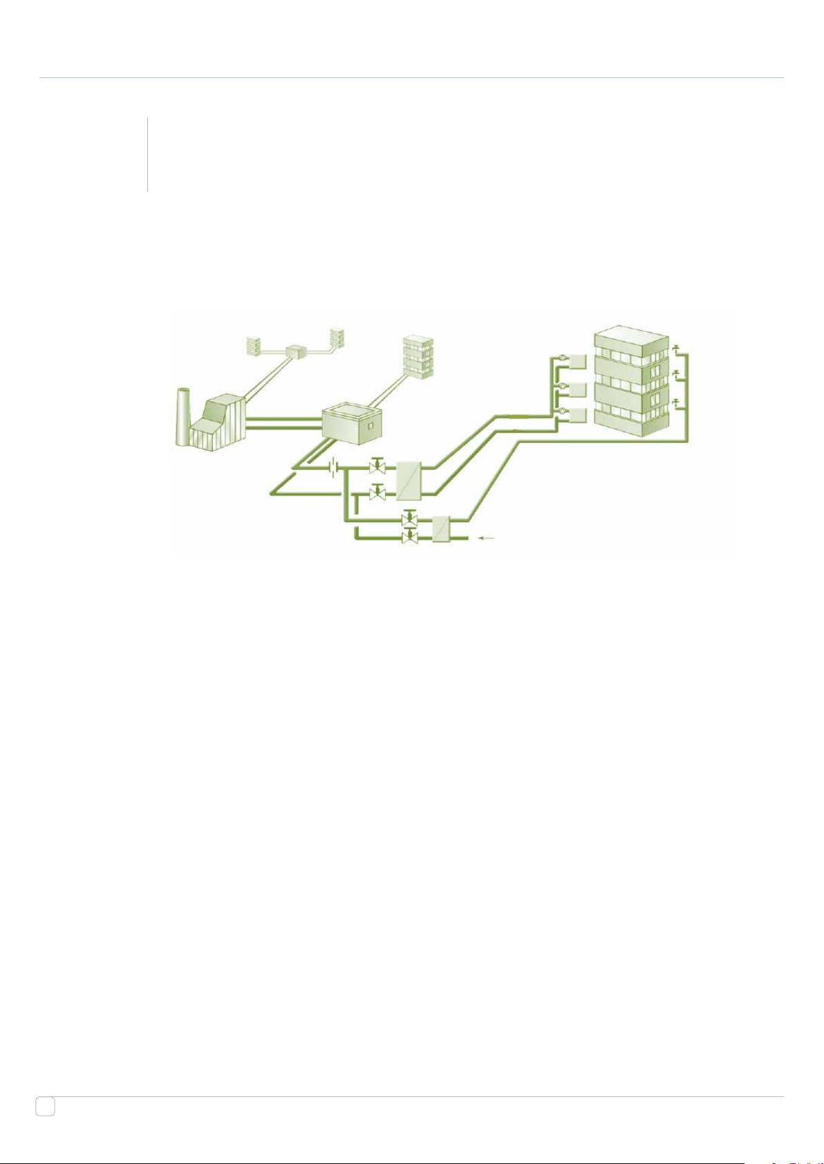
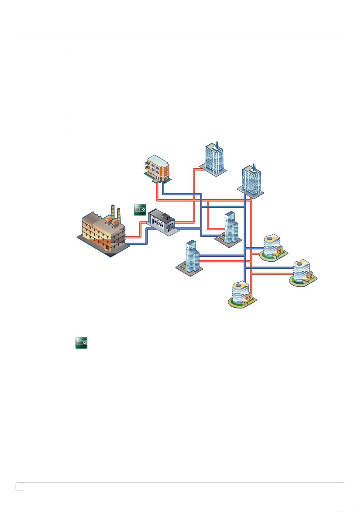
Connection of the building to the grid designed at 80ths old constructed District heating systems with network
structure as presented on the pic. 2 still have a high presence on the market.
Distribution
station
Building sub-
Source
station
Figure 2: District heating network
A brief overview of old District Heating Nets can be characterized by following:
• Weather compensated temperature control only at the heat source (combined heat power plants, boiler
installations)
• High level of heat losses
• High cola consumptions
• High demand for better water treatment
• Constant ow in primary and secondary circuits.
• Overspecied pumps
• Excessive consumption of heat and electric power
• Lack of comfort conditions for end-users
• High return temperature on Primary Side
• Hydraulic unbalance
• Energy ineciency
Domestic hot water system (DHW)not-connected to the District heating system and prepared by electrical /gas
10
boiler. In the regions Solar panels also used for DHW systems
Page 11
1.2
Common problems of the current District Heating
systems in China and their causes.
1.21
Heat losses in networks
Generally, the heat networks has been designed and constructed in 80s years of the last century. Since then
constant economic growth and industrial development required continual construction of new networks, while
the old ones practically were not reconstructed. Total heat losses reach ~ of the consumer heat load.
It is possible to distinguish two components of heat losses:
Heat losses
Leakage
Figure 3: Type of heat loses
Losses due to leakages:
This issues caused by all-round wearing of the heat networks. Corrosion makes holes in pipeline walls, bad seal
Loses from surface -
non insulated
in valves and between ange connections, which results in leaks.
Losses from pipeline surfaces:
Heat network pipelines are made of steel, which is an excellent thermal conductor. As it can be seen from the
following expression, this type of losses depends on a number of factors; among those are thermal conductivity
of the material and the dierence between the external air and the heat carrier temperatures.
Q =λ· (t1– t2) · F.
Lack of insulation, as well as the heat carrier temperature in the supply pipe, which is as high as 130 C, results in
2
heat losses of ~ Gcal per m
Insulation of the pipeline and decrease of the operating parameters allows lowering the losses down to ~ per
1 running meter
Conclusion:
Total heat losses reach 273 million Gcal per year, which amounts to 34.745 billion RMB in cash equivalent.It is
11
Page 12
impossible to solve the issue by mere replacement of pipelines: this will require huge manpower,
material and time resources. Measures, which can be taken now, are reduction of the temperature
curve and all-round insulation of pipelines. This will signicantly reduce the heat losses and grant
additional time, required for gradual reconstruction and replacement of heat networks.
1.22
Hydraulically unbalanced networks
Present-day heat supply systems of residential, production and administration buildings are con-
nected to heat networks via central substations. Consumer heat loads are unstable and, as a result of
quantity and quality regulation, which takes place at the heat source. This is a serious issue obviously
take place in heavily branched heat networks, due to their unbalance. Function of limitation of
maximal heat carrier ow by end consumer is also quite hard to implement.
Currently, hydraulic balancing of a heat network is carried out at the design conditions by means of
throttling orices or, at the best, by means of manual balancing valves or circulating pumps with
variable frequency converters. Resistance of the latter can be calculated by the following expression:
However, it is impossible to achieve balance between the quantity and quality regulated heat
network and consumers by means of the throttling devices, because as the ow changes from G1
to G2, hydraulic resistance of an orice or a manual balancing valve, which have constant hydraulic
characteristics (Kv), changes as square of the ow.
12
ΔРа ΔРb
А
ΔРc ΔРd
С
В
D
Figure 4: Standard piezometric diagram
Orices and manual valves can be used for balancing in systems with constant ow only. Quantity
and quality regulation in heat networks balanced by means of these devices results in oating piezo-
Page 13
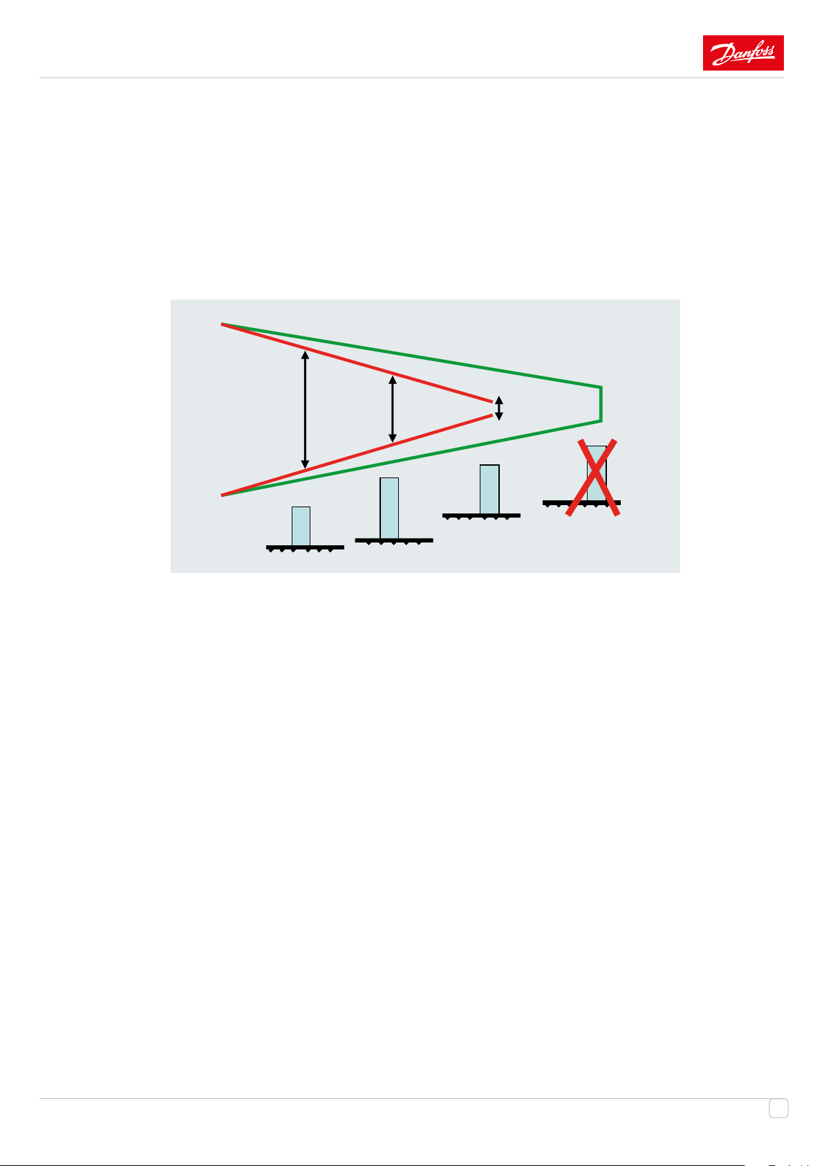
metric curve and, as a consequence, variable local pressure drops at building connection.
Similarly, usage of circulating pumps with variable frequency converters does not meet the expectations laid
on it. Indeed, total pressure of an unbalanced network does not change; excessive pressure and ow (which are
built up locally as the result of operation of automatic equipment and local decrease of the heat carrier ow)
are simply redistributed to the nearest objects. Thus variable frequency driving actuators do not perform their
primary function
ΔРа
ΔРb ΔРc
В
А
С
ΔРd=0
D
.
Figure 5: Piezometricschedulefor peakheat loadsperiod
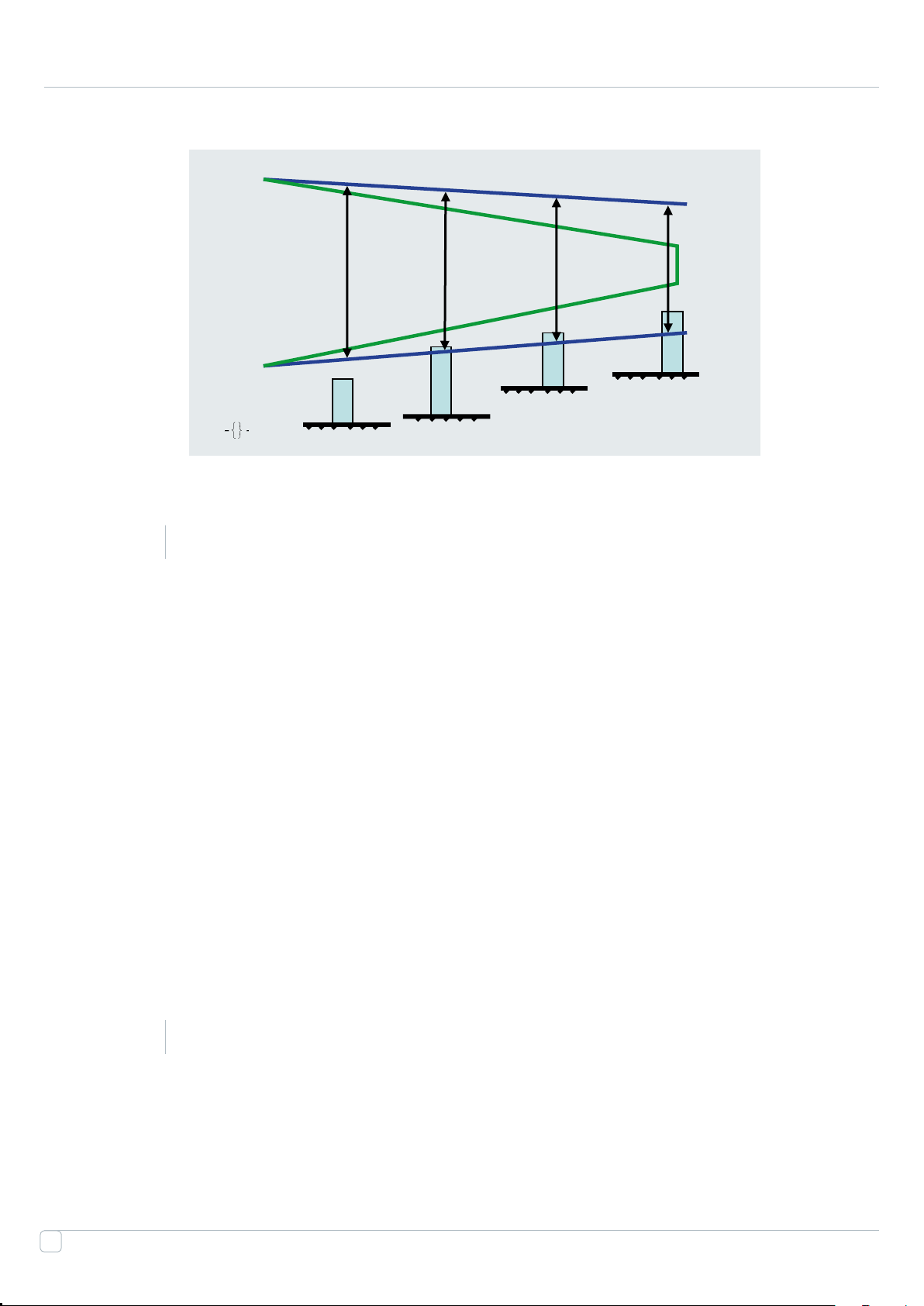
Existence of the oating piezometric curve makes it impossible to limit the maximal ow by means of orices
and manual balancing valves. Limitation of maximal ow, as well as hydraulic balancing of systems with varia-
ble ow can be carried out by means dierential pressure controllers only. Such controllers are capable to main-
tain the stable pressure drop in the regulated variable ow system. In case of increase of the input pressure they
ensure stable limitation of the maximal heat carrier ow. With usage of such controllers, "internal" hydraulic
balancing of heat networks at every central substation and building substation is no longer required. Orices
and manual balancing valves can be removed from pipelines: balanced distribution of the heat is achieved due
to additional hydraulic resistance of the DP controllers located at heat stations in each building.
Dismissal of quarterly balancing of heat networks invalidates the piezometric curve (there is no more local loss-
es at orices and manual balancing valves), the former "problem" objects receive local pressure drop required
for their operation. In centralized thermal supply systems these measures lead to signicant economic eect.
Circulation pumps of the heat networks instantly obtain the required pressure. Such heat power reserves make
it possible to connect additional consumers to the existing networks without considerable capital costs.
13
Page 14
ΔРа ΔРb ΔРd
А
В
ΔРc
С
Figure 6: The reduction of the circulationowinheating systems
D
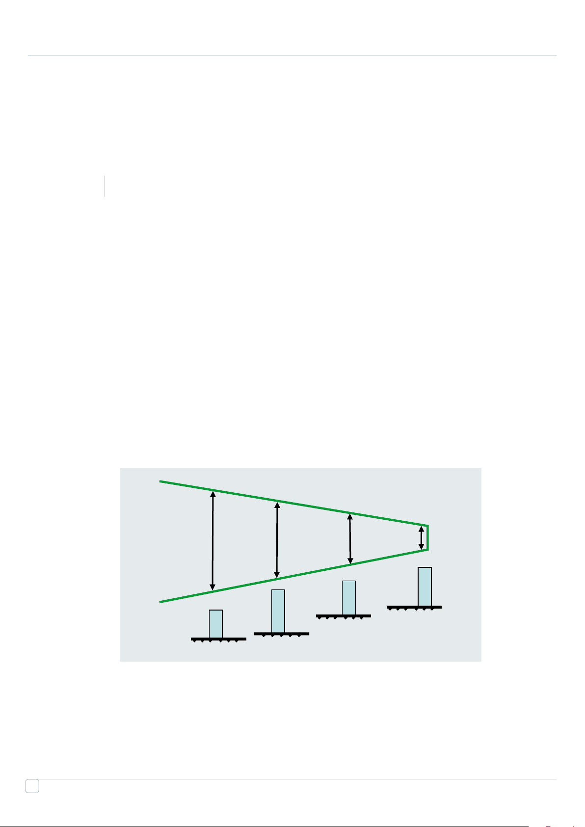
1.23
Over specied pumps
Another important issue, which requires attention, is over specied pumps installed at the heat
source thermal chambers and central heat supply stations. What is the reason of this problem? Why
does it have an negative inuence? The pumps are selected in assumption that the most distant
consumer must receive the heat carrier at the maximal ow, i.e. taking into account the maximal
hydraulic resistance. As the result, consumers located closer to the heat source or the central heat
supply station experience signicant "harmful" pressure, which must be decreased (wasting of
energy). Large safety factors stipulated by the network design are also not always useful. An over
specied pump operates in non-optimal conditions, which lowers its eciency (ref. the gure
above), increases electric energy consumption, decreases the life-time and heightens the noise level.
Currently, more and more systems are transferred to dynamic model of operation, and installation of
variable frequency converters becomes a requirement. If it is not possible to replace the pump itself,
the frequency converter will maximally optimize its operation in various operating modes.
In addition to all the mentioned above, usage of Overspecied pumps results in increase of capital
and operating costs.
14
1.24
Lack of centralized hot water treatment for DHW systems
Currently, only local water heaters installed directly in consumers' buildings are used. This results not
just in increased consumption of electric energy and gas, which can be used much more eectively.
It is well known that heating is not needed in summer, and the corresponding network pipelines are
Page 15

drained. As the result, internal pipe surface contacts with air, which speeds up corrosion in several times, which,
in turn, ruins leak-proofness of the pipes and increases heat losses resulted by leaks.
1.25
General energy ineciency of the heat supply system
All the above mentioned issues make a common image of the situation. Unfortunately, it is necessary to state
that the heat supply system stays generally inecient in spite of the eorts being applied. Renewal and recon-
struction of the large-scale systems require huge amounts of resources: time, money, manpower. Besides, the
problems of the heat supply system aect the allied industries:
Electric power industry (additional loads: water heaters in buildings, pump driving actuators)
Mining operations (additional loads: fuel for combined heat power plants and boiler installations)
Objective set by the Government of China is real and achievable. The future and economy of the country
depends on achievement of this objective. Yes, the capital costs are relatively high, however, in 5 - 10 years
benets of the modernization will signicantly exceed this value and open new horizons of development.
Danfoss has capabilities, experience and complete solutions which solving these issues. Some solutions,
described below, are widespread in Europe and also in Russia. Advantages of Danfoss' solution is:
• Decreased environmental impact,
• Energy saving,
• Decreased pay-back time,
• Improved comfort for tenants.
15
Page 16
2
2.1
Connection to the grid
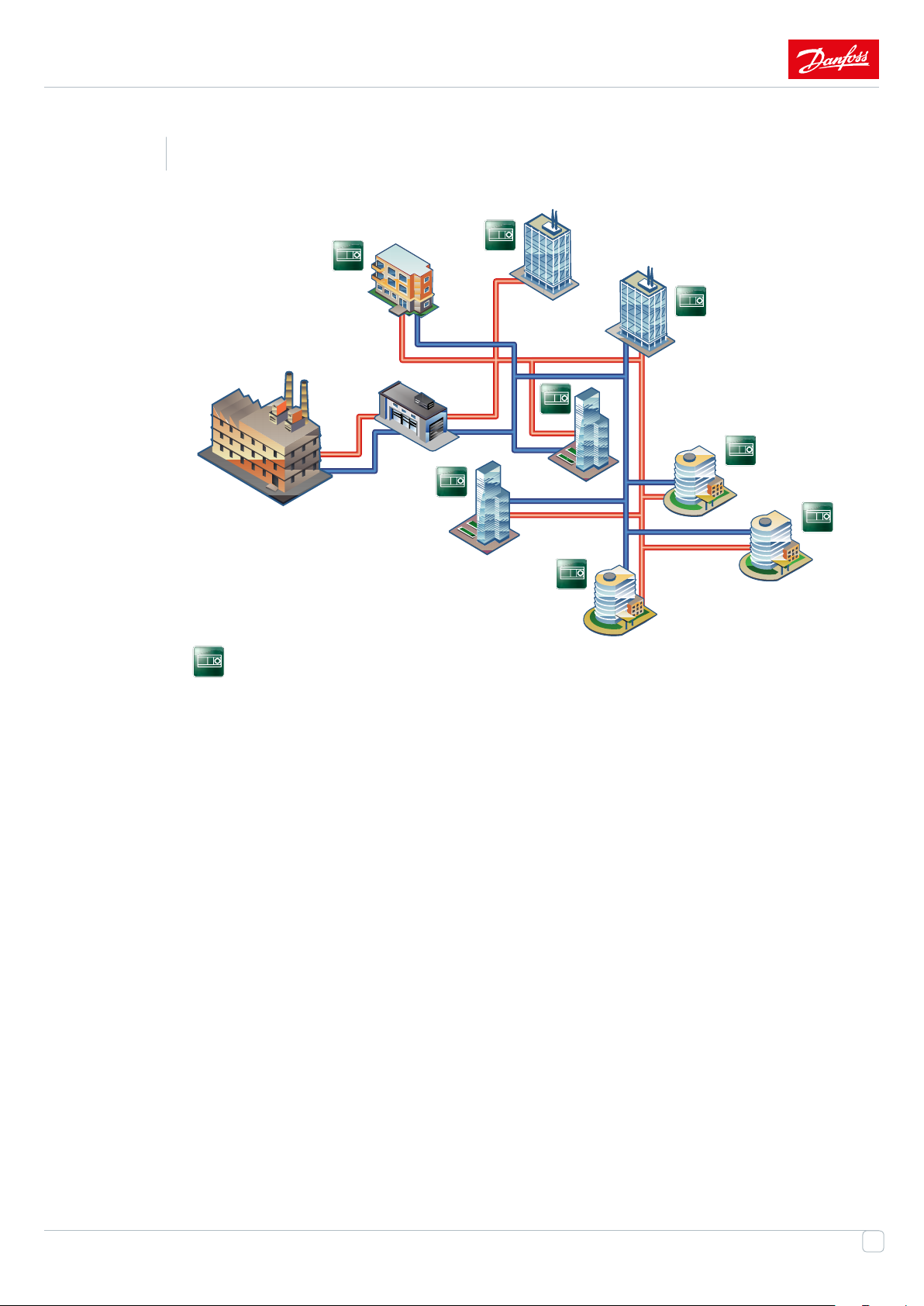
Central substation equipped by weather compensator, no controls in the building – direct connec-
tion of the buildings
16
Weather Compensation
Page 17

One of the solution,
Weather compensated temperature control at the heat source (combined heat power plants, boiler
installations)
• Weather dependent temperature control at central substations
• Local temperature control: thermostats installed on end consumers' radiators
• Variable ow in primary and secondary circuits.
• Manual balancing valves at building connections
• Domestic hot water system not connected to the District heating system and prepared by electri-
cal /gas boiler. In the regions Solar panels also used to control the water
The main disadvantage of such model is that the consumer is provided with sucient amount of
heat only in case the necessary specications of the network and the heat source are precisely met
and constant (because consumers are unable to adjust ow and, consequently, temperature)
Such model could be deemed viable earlier, prior to total upgrade of heat sources, Heat networks
and heating systems. However, usage of such models gets more and more undesirable. Consumers
and the Heat network experience almost all the problems mentioned above, like:
• Excessive consumption of heat and electric power
• Excessive temperature of the returning heat carrier
• Hydraulic unbalance
• Energy ineciency
• High rates of corrosion in the summer months
17
Page 18
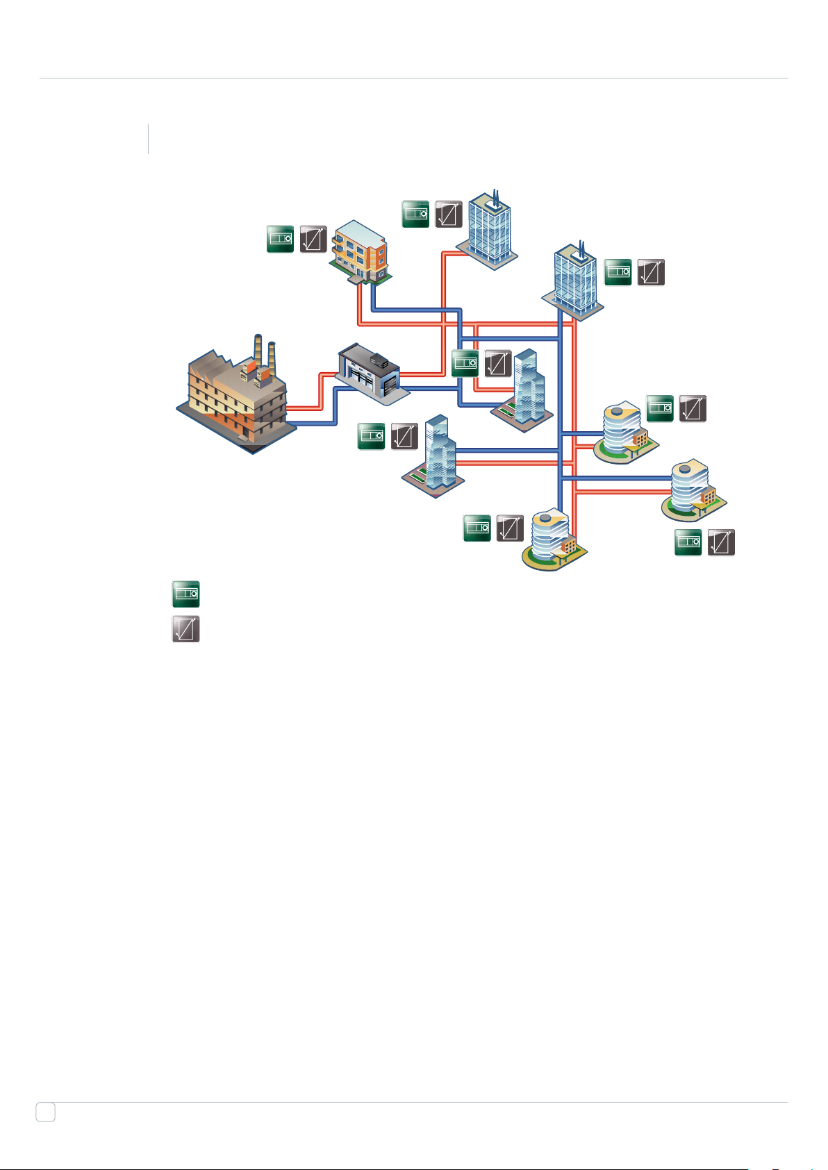
2.2
Central substation equipped by weather compensator. Few buildings had Mixing units or
substation at the entrance
Weather Compensation
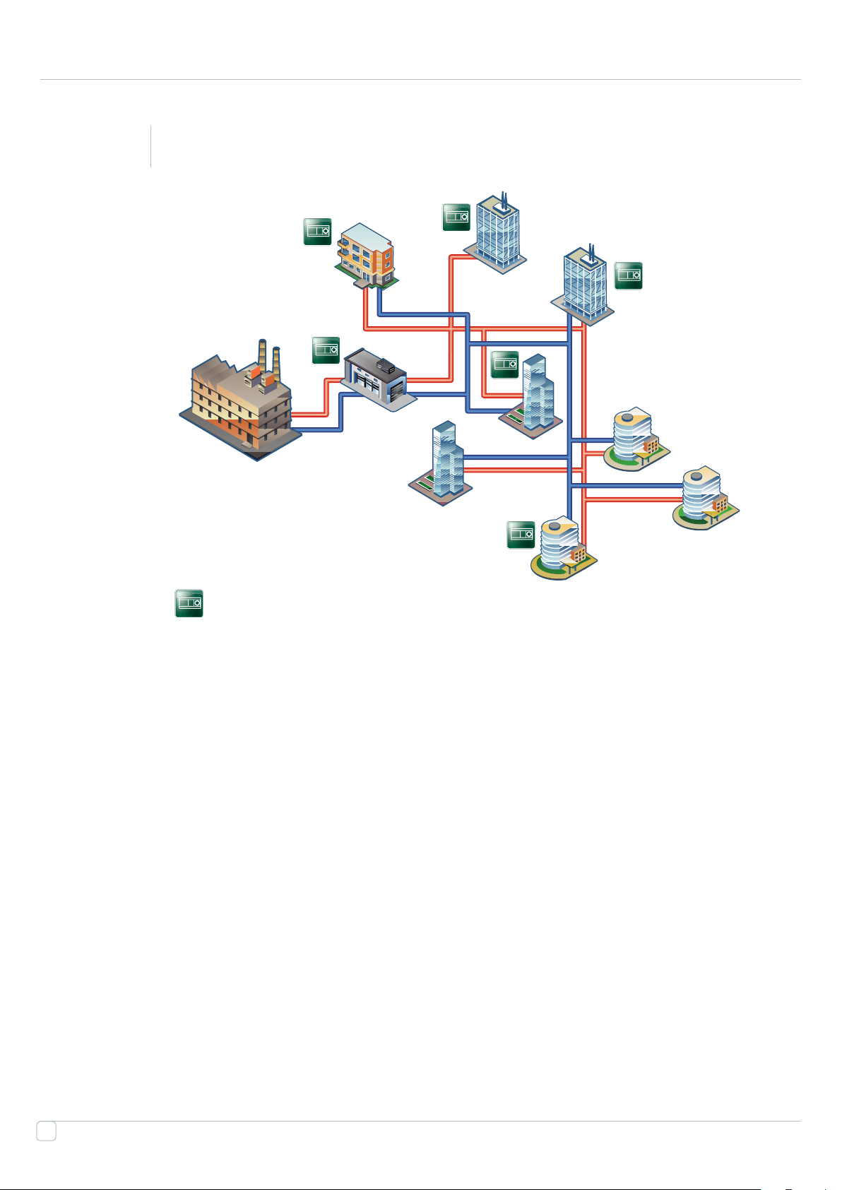
The second case is inseparably linked with progressive partial automation of buildings and end users, which,
as it was mentioned in section 1, threatens the whole system. Weather compensators close and open valves
in order to achieve the conditions conformable for the user. If such consumers become too large in number,
the other consumers become aected. Consumers not equipped with automation or even Dierential pressure
controllers may face with the following diculties and problems:
• Increase of pressure in return pipelines
• Pressure oscillation
• Overheating of premises
• Insucient heating
18
Page 19
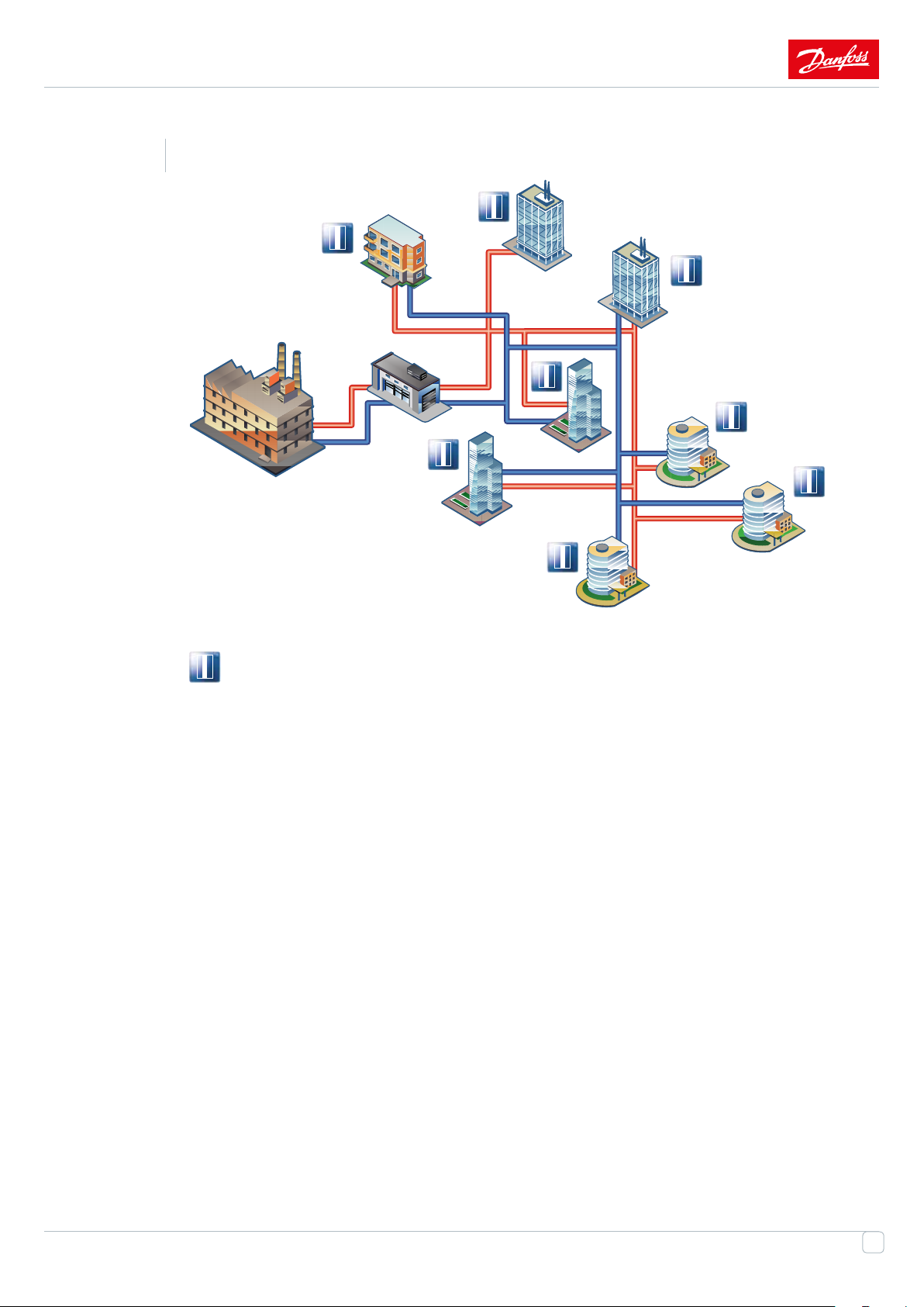
2.3
Central Substations with mixing loops at each building or every connection
Weather Compensation
For the renovation of the District Heating Nets, one of the compromised solutions might be installation in each
building the mixing loops for Heating system with keeping the Central Substations for the group of buildings.
Temperature and heat controlled based on the weather compensation principle to the consumer (right in the
building) compare to the previous solutions. Thus lead to increased energy-eciency and energy savings on the
level of 15-20%.
PICV or combination of DPC + MCV secure the hydronic stability, ow limitation and reduce the risk for cavita-
tion and pressure oscillations in the system. Needles to mark that by using DPC, hydronic stability achieved as
for primary as for secondary sides.
19
Page 20
2.4
Substations in each building
Weather Compensation
HEX
Indirect connections are used regardless of pressure value in the point of connection to the Heat network, which
means that such models are versatile. Hydraulic insulation between the heating systems and the Heat network
signicantly raises reliability of thermal supply systems, protects local systems from increase and decrease of
pressure in the Heat network, and allows keeping water in the heating system in case of emergency, because it
is prevented from freezing due to circulating pumps operation..
For consumer benets are:
• Comfort parameters due to the weather compensation
• Stable and accurate controls of parameters as in on the secondary as on primary sides
• Independence of system from other buildings
• HIGH energy eciency – for heat and for electricity
• HIGH energy savings – up to 25%
20
Page 21
2.5
Flat stations in each at for the same district
Icon of Flat station
The decentralized heating system comprises an installation, for which at stations built into each apartments
that are supplied from a central energy source. These units normally incorporate a compact plate heat ex-
changer, which delivers instantaneous DHW on demand and a dierential pressure control valve to control the
heating ow to the tenants’ radiators or oor heating.
The essence of decentralized heating systems is in moving certain processes from the central substation to the
individual ats.
In order to secure optimum system performance of the at station it is important to dimension the system
correctly. A dimensioning tool provided by Danfoss provides an easy way for correctly dimensioning the at station.
Ref: eFlat dimensioning tool at danfoss.com
Decentralized systems can operate with all available energy sources. The most frequently used are either an
indirect DH substation, any other directly connected substation or boiler installation. All the sources can be
combined with solar.
The benets of having a at stations compared to traditional systems include
• Accurate individual energy metering
21
Page 22

Space-saving and easy to install
•
• Increased energy eciency through improved system operation and low operational
temperatures, suitable for low temperature systems
• Hydraulic balance in the system
• Reduced maintenance costs due to simple and reliable technology
• Individual setting of room temperature and independent instantaneous DHW preparation in
sucient quantities provides maximum comfort
• Independency of energy source
2.6
Conclusion
Objective set by the Government of China is real and achievable. The future and economy of the
country depends on achievement of this objective. Yes, the capital costs are relatively high, howev-
er, in 5 - 10 years benets of the modernization will signicantly exceed this value and open new
horizons of development.
Danfoss has capabilities, experience and complete solutions which solving these issues. Some solu-
tions, described below, are widespread in the world. . Advantages of Danfoss' solution:
• Decreased environmental impact,
• Energy saving,
• Decreased pay-back time,
• Improved comfort for tenants.
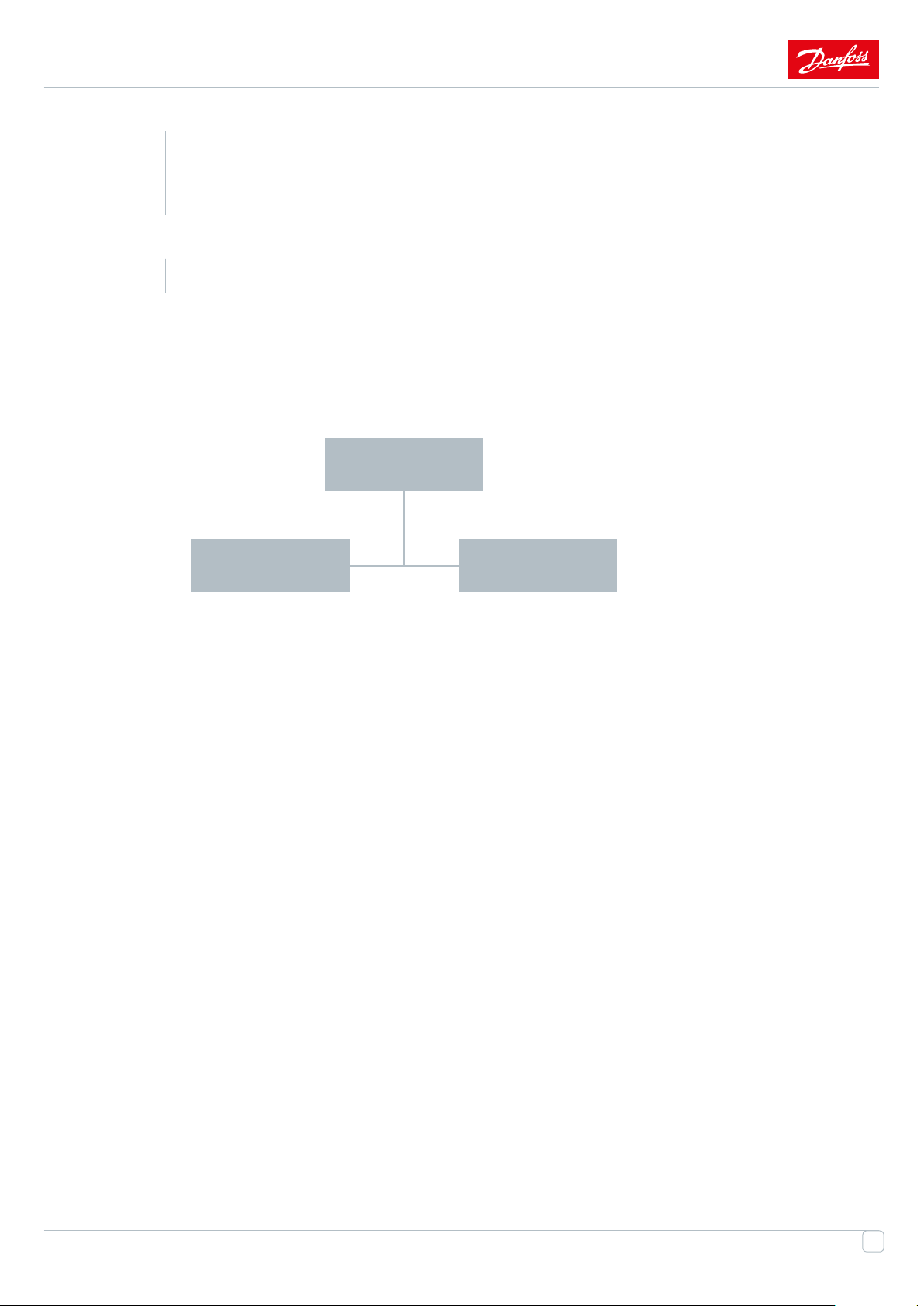
Classication of solutions Level of energy-eciency
No control Very low
Control in few buildings LOW
CHP with ML MEDIUM
IHP HIGH
Flat stations in each apartment VERY HIGH
22
Page 23

23
Page 24

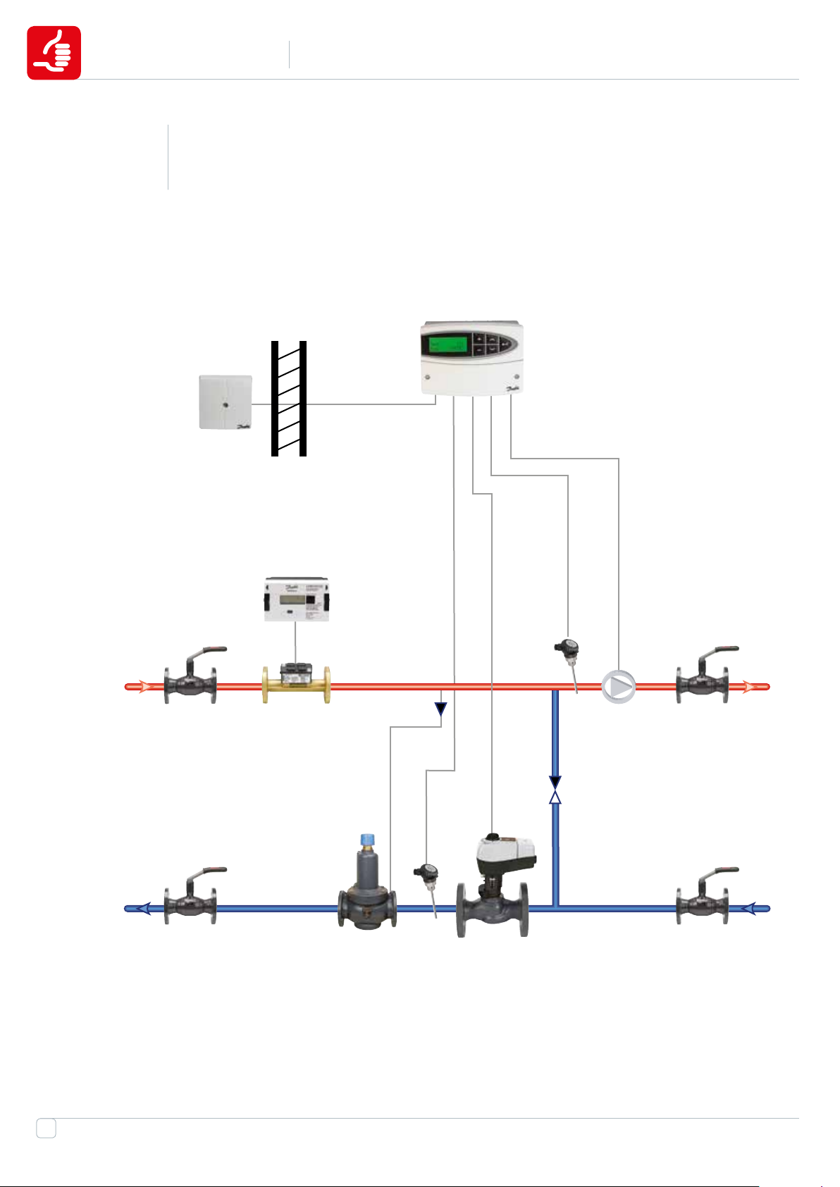
RECOMMENDED*
Direct connection of Heating system
Application
3
3.1
(connected via Central substations)
Mixing loop with Weather compensation and Combination valves for
the Heating systems
ECL
TS
HM
BV
BV TS
TS
BV
PICV
BV
24
Page 25

System analysis
Design / Sizing
1
• SIMPLIFIED HYDRONIC CALCULATION REQUIRED
• Pump head calculation according nominal ow
• Place on Pump installation depends on Static pressure in the net and
system
Operational cost
2
• Limited operational cost due to unstable hydraulic balance (no stabiliza-
tion of DP)
• Low periodical Check-up costs due to the limited amount of equipment
• Power consumption of pump depends on system and place of installation
• Very low amortization costs due to limited amount of equipment
Investment
3
• Investment cost – LOW (Weather compensator +combined valves )
• Installation cost – VERY LOW
• Commissioning cost for weather compensator and combi-valve - ME
DIUM
4
5
Energy savings
• MEDIUM ENERGY SAVING due to the Weather compensation and low
• LOW RISK OF OVERFLOW due to the ow limitation on combi valves,
• HIGH HEAT CONSUMPTION than outside temperature higher than calcu-
lated
Control stability
• Stability at full load, and very good stability on partial load
• MEDIUM risk of emergency – internal Dp controller in PICV protect sec-
ondary side from pressure uctuations on primary side
• LOW RISK of pressure oscillation in DH Nets due to the integrated DPC in
PIBCV
• LOW RISK FOR CAVITATION
25
Page 26
RECOMMENDED*
Mixing-loop for Heating system, recommended than dP less than 2
3.2
bar
Application
ECL
TS
BV
BV
HM
DPC
TS
TS
BV
BV
MCV
26
Page 27

System analysis
Design / Sizing
1
• TRADITIONAL CALCULATION REQUIRED FOR MCV AND DPC: Kvs and
authority of the valves, dP presetting for DPC
• PLACE OF THE DPC AND MCV INSTALLATION DEPENDS ON THE CUR
RENT PIEZOMETER
• Pump head calculation according nominal ow
• Place of pump installation depends on available dierential pressure
Operational cost
2
• LOW operational cost due to stable hydraulic balance (stabilization of dP)
• MEDIUM periodical check-up costs due to the limited amount of equip-
ment
• Power consumption of pump depends on system and place of installation
• MEDIUM amortization costs due to amount of equipment
3
4
5
Investment
• Investment cost – MEDIUM
• Installation cost – MEDIUM
• Commissioning cost for weather compensator and combi-valve -
MEDIUM
Energy savings
• MEDIUM ENERGY SAVING due to the Weather compensation
• LOW RISK OF OVERFLOW due to the ow limitation obtained by special
presetting procedure of DPC
Control stability
• Stability at full load, and very good stability on partial load
• LOW risk of emergency – DPC protect secondary side from pressure uc-
tuations on primary side
• LOW risk of pressure oscillation in the DH net due to the DPC
• LOW risk for cavitation
27
Page 28

RECOMMENDED*
3.3
Application
Mixing loop with 3-way valves to be used if the temperature in
primary and secondary systems are equal
ECL
TS
HM
DPC
BV
BV TS
MCV
BVTS
BV
28
Page 29

System analysis
Design / Sizing
1
• TRADITIONAL CALCULATION REQUIRED FOR MCV AND DPC: Kvs and
authority of the valves, dP presetting for DPC
• PLACE OF THE DPC INSTALLATION DEPENDS ON THE CURRENT
PIEZOMETER
• Pump head calculation according nominal ow
• Place of pump installation depends on available dierential pressure
Operational cost
2
• Low operational cost due to stable hydraulic balance (stabilization of dP)
• Medium periodical check-up costs due to the limited amount of equip-
ment
• Power consumption of pump depends on system and place of installation
• MEDIUM amortization costs due to amount of equipment
3
4
5
Investment
• Investment cost – MEDIUM
• Commissioning cost - HIGH for weather compensator and DPC
Energy savings
• MEDIUM ENERGY SAVING due to the Weather compensation
• LOW RISK OF OVERFLOW due to the ow limitation obtained by special
presetting procedure of DPC
Control stability
• Stability at full load, and very good stability on partial load
• Low risk of emergency – DPC protect secondary side from pressure uc-
tuations on primary side
• Low risk of pressure oscillation in the DH net due to the DPC
29
Page 30

ACCEPTABLE*
Mixing loop for Heating system with Weather compensation, Motor-
3.4
ized Control Valves and Manual Balancing valves
TS
Application
ECL
SMBV
BV
HM
TS
MCV
BV
TS
BV
30
Page 31

System analysis
Design / Sizing
1
• TRADITIONAL CALCULATION REQUIRED FOR MCV: Kvs and authority of
the valves
• Presetting calculation of Balancing valves is needed
• Pump head calculation according nominal ow
• Place on Pump installation depends on Static pressure in the net and
system
Operational cost
2
• HIGH operational cost due to unstable hydraulic balance (no stabilization
of DP)
• Medium periodical Check-up costs due to the limited amount of equip-
ment
• Power consumption of pump depends on system and place of installation
• Low amortization costs due to limited amount of equipment
3
4
5
Investment
• Investment cost – MEDIUM (control valve + Weather compensator +
Manual Balancing valves) installation cost - MEDIUM
• Commissioning cost – AVERAGE for weather compensator and balancing
valves
Energy savings
• MEDIUM ENERGY SAVING due to the Weather compensation and max
ow limitation
• RISK OF OVERFLOW due to the ow limitation by balancing valve
• HIGH HEAT CONSUMPTION than outside temperature lower
Control stability
• Stability only at full load, but on partial load VERY LOW
• HIGH risk of emergency – non protection of secondary side from pressure
uctuations
• VERY HIGH risk of cavitation
• HIGH risk of pressure oscillation in DH Nets
31
Page 32

NOT RECOMMENDED NOT RECOMMENDED NOT RECOMMENDED NOT RECOMMENDED NOT RECOMMENDED NOT RECOMMENDED NOT RECOMMENDED
NOT RECOMMENDED*
Application
NOT RECOMMENDED NOT RECOMMENDED NOT RECOMMENDED NOT RECOMMENDED NOT RECOMMENDED NOT RECOMMENDED NOT RECOMMENDED
Mixing loop for Heating system with Weather compensation and
3.5
motorized control valves for the systems with T in secondary side
NOT RECOMMENDED NOT RECOMMENDED NOT RECOMMENDED NOT RECOMMENDED NOT RECOMMENDED NOT RECOMMENDED NOT RECOMMENDED
equal to T on primary side
NOT RECOMMENDED NOT RECOMMENDED NOT RECOMMENDED NOT RECOMMENDED NOT RECOMMENDED NOT RECOMMENDED NOT RECOMMENDED
NOT RECOMMENDED NOT RECOMMENDED NOT RECOMMENDED NOT RECOMMENDED NOT RECOMMENDED NOT RECOMMENDED NOT RECOMMENDED
ECL
NOT RECOMMENDED NOT RECOMMENDED NOT RECOMMENDED NOT RECOMMENDED NOT RECOMMENDED NOT RECOMMENDED NOT RECOMMENDED
TS
NOT RECOMMENDED NOT RECOMMENDED NOT RECOMMENDED NOT RECOMMENDED NOT RECOMMENDED NOT RECOMMENDED NOT RECOMMENDED
NOT RECOMMENDED NOT RECOMMENDED NOT RECOMMENDED NOT RECOMMENDED NOT RECOMMENDED NOT RECOMMENDED NOT RECOMMENDED
HM
NOT RECOMMENDED NOT RECOMMENDED NOT RECOMMENDED NOT RECOMMENDED NOT RECOMMENDED NOT RECOMMENDED NOT RECOMMENDED
TS
NOT RECOMMENDED NOT RECOMMENDED NOT RECOMMENDED NOT RECOMMENDED NOT RECOMMENDED NOT RECOMMENDED NOT RECOMMENDED
BV
BV
NOT RECOMMENDED NOT RECOMMENDED NOT RECOMMENDED NOT RECOMMENDED NOT RECOMMENDED NOT RECOMMENDED NOT RECOMMENDED
NOT RECOMMENDED NOT RECOMMENDED NOT RECOMMENDED NOT RECOMMENDED NOT RECOMMENDED NOT RECOMMENDED NOT RECOMMENDED
TS
NOT RECOMMENDED NOT RECOMMENDED NOT RECOMMENDED NOT RECOMMENDED NOT RECOMMENDED NOT RECOMMENDED NOT RECOMMENDED
NOT RECOMMENDED NOT RECOMMENDED NOT RECOMMENDED NOT RECOMMENDED NOT RECOMMENDED NOT RECOMMENDED .RECOMMENDED NOT RECOMMENDED
32
BV
MCV
BV
Page 33

System analysis
Design / Sizing
1
• TRADITIONAL CALCULATION REQUIRED FOR MCV: Kvs and authority of
the valves
• Pump head calculation according nominal ow
• Place on Pump installation depends on Static pressure in the net and
system
Operational cost
2
• HIGH operational cost due to unstable hydraulic balance (no stabilization
of DP)
• MEDIUM periodical Check-up costs due to the limited amount of equip-
ment
• Power consumption of pump depends on system and place of installation
• Very low amortization costs due to limited amount of equipment
3
4
5
Investment
• Investment cost – MEDIUM (control valve + Weather compensator +
pump)
• Low installation cost - - MCV + Strainer + shut-o valves
• Low commissioning cost for weather compensator
Energy savings
• MEDIUM ENERGY SAVING due to the Weather compensation
• HIGH RISK OF OVERFLOW due to the lack of ow limitation (no hydraulics
balance products on the loop),
• HIGH HEAT CONSUMPTION than outside temperature higher than
Control stability
• LIMITED stability, only in case when ow on secondary side is const. and
pressure on primary is also stable
• HIGH risk of emergency – non protection of secondary side from pressure
uctuations
• HIGH risk of pressure oscillation in DH Nets
• VERY HIGH risk of cavitation
33
Page 34

RECOMMENDED
Indirect connection of Heating system
Application
4
4.1
(Direct connection to the primary circuit)
Indirect connection of Heating system with DPC and MCV. DPC play
also role of Flow limiter
ECL
TS
34
BV
BV
HM
HM
DPC
TS
BVTS
BV
MCV XG
Page 35

System analysis
Design / Sizing
1
• TRADITIONAL CALCULATION REQUIRED FOR MCV AND DPC: Kvs and
authority of the valves, dP presetting for DPC
• Pump head calculation according nominal ow
• Place of valves installation depends on available dierential pressure in
the primary side.
Operational cost
2
• Low operational cost due to stable hydraulic balance (stabilization of DP)
• Medium periodical check-up costs due to the limited amount of equip-
ment
• Power consumption of pump depends on system and place of installation
• Very low amortization costs due to limited amount of equipment
3
4
5
Investment
• Investment cost – MEDIUM
• High commissioning cost for weather compensator and DP controller
Energy savings
• MEDIUM ENERGY SAVING due to the Weather compensation and
• LOW RISK OF OVERFLOW due to the ow limitation obtained by special
presetting procedure of DPC
Control stability
• Stability at full load, and very good stability on partial load
• LOW risk of pressure oscillation on DH nets
• LOW risk for cavitation
35
Page 36

RECOMMENDED*
Indirect connection of Heating system with DPCQ and MCV. DPCQ
4.2
secure automatic flow limitation
TS
Application
ELC 110
ECL
DPCQ
BV
BV HM TS
BVTS
BV
MCV XG
36
Page 37

System analysis
Design / Sizing
1
• TRADITIONAL CALCULATION REQUIRED FOR MCV AND DPC: Kvs and
authority of the valves, dP presetting for DPC
• Pump head calculation according nominal ow
• Place of valves installation depends on available dierential pressure in
the primary side.
Operational cost
2
• Low operational cost due to stable hydraulic balance (stabilization of DP)
• Medium periodical check-up costs due to the limited amount of equip-
ment
• Power consumption of pump depends on system and place of installation
• Very low amortization costs due to limited amount of equipment
3
4
5
Investment
• Investment cost – MEDIUM
• High commissioning cost for weather compensator and DPCQ controller
Energy savings
• ENERGY SAVING due to the Weather compensation
• NO RISK OF OVERFLOW due to the ow limitation obtained by DPCQ
Control stability
• Very good stability of control as at full as on partial load
• VERY LOW risk of pressure oscillation on DH nets
• VERY LOW risk for cavitation
37
Page 38

RECOMMENDED*
Indirect connection of HE system with PIBCV
4.3
TS
Application
ECL
BV
BV
HM
TS
PICV
XG
TS
BV
BV
38
Page 39

System analysis
Design / Sizing
1
• SIMPLIFIED HYDRONIC CALCULATION REQUIRED
• Pump head calculation according nominal ow
• Place of the installation of PICV depends on the evaluable dierential pres-
sure. Installation on return pipe is preferable due to the low parameters
Operational cost
2
• Limited operational cost due to unstable hydraulic balance (no stabiliza-
tion of DP)
• Low periodical Check-up costs due to the limited amount of equipment
• Power consumption of pump depends on system and place of installation
• Very low amortization costs due to limited amount of equipment
Investment
3
• Investment cost – LOW (Weather compensator +combi valves )
• Installation cost - LOW
• Commissioning cost -LOW for weather compensator and PICV
4
5
Energy savings
• MEDIUM ENERGY SAVING due to the Weather compensation and max
ow limitation
• LOW RISK OF OVERFLOW due to the ow limitation
• HIGH HEAT CONSUMPTION than outside temperature lower than calcu-
lated one
Control stability
• Stability at full load, and very good stability on partial load
• LOW risk of pressure oscillation on DH nets
• LOW risk for cavitation
39
Page 40

NOT RECOMMENDED NOT RECOMMENDED NOT RECOMMENDED NOT RECOMMENDED NOT RECOMMENDED NOT RECOMMENDED NOT RECOMMENDED
ACCEPTABLE*
Application
NOT RECOMMENDED NOT RECOMMENDED NOT RECOMMENDED NOT RECOMMENDED NOT RECOMMENDED NOT RECOMMENDED NOT RECOMMENDED
Indirect connection of HE system with MBV and MCV
4.4
NOT RECOMMENDED NOT RECOMMENDED NOT RECOMMENDED NOT RECOMMENDED NOT RECOMMENDED NOT RECOMMENDED NOT RECOMMENDED
NOT RECOMMENDED NOT RECOMMENDED NOT RECOMMENDED NOT RECOMMENDED NOT RECOMMENDED NOT RECOMMENDED NOT RECOMMENDED
ECL
NOT RECOMMENDED NOT RECOMMENDED NOT RECOMMENDED NOT RECOMMENDED NOT RECOMMENDED NOT RECOMMENDED NOT RECOMMENDED
TS
NOT RECOMMENDED NOT RECOMMENDED NOT RECOMMENDED NOT RECOMMENDED NOT RECOMMENDED NOT RECOMMENDED NOT RECOMMENDED
NOT RECOMMENDED NOT RECOMMENDED NOT RECOMMENDED NOT RECOMMENDED NOT RECOMMENDED NOT RECOMMENDED NOT RECOMMENDED
HM
NOT RECOMMENDED NOT RECOMMENDED NOT RECOMMENDED NOT RECOMMENDED NOT RECOMMENDED NOT RECOMMENDED NOT RECOMMENDED
TS
NOT RECOMMENDED NOT RECOMMENDED NOT RECOMMENDED NOT RECOMMENDED NOT RECOMMENDED NOT RECOMMENDED NOT RECOMMENDED
SMBV
NOT RECOMMENDED NOT RECOMMENDED NOT RECOMMENDED NOT RECOMMENDED NOT RECOMMENDED NOT RECOMMENDED NOT RECOMMENDED
TS
BV
BV
MCV
XG
BV
NOT RECOMMENDED NOT RECOMMENDED NOT RECOMMENDED NOT RECOMMENDED NOT RECOMMENDED NOT RECOMMENDED NOT RECOMMENDED
NOT RECOMMENDED NOT RECOMMENDED NOT RECOMMENDED NOT RECOMMENDED NOT RECOMMENDED NOT RECOMMENDED NOT RECOMMENDED
NOT RECOMMENDED NOT RECOMMENDED NOT RECOMMENDED NOT RECOMMENDED NOT RECOMMENDED NOT RECOMMENDED NOT RECOMMENDED
NOT RECOMMENDED NOT RECOMMENDED NOT RECOMMENDED NOT RECOMMENDED NOT RECOMMENDED NOT RECOMMENDED .RECOMMENDED NOT RECOMMENDED
40
Page 41

System analysis
Design / Sizing
1
• TRADITIONAL CALCULATION REQUIRED FOR MCV AND MBV: Kvs and
authority of the valves
• Presetting calculation of Balancing valves is needed
• Pump head calculation according nominal ow
Operational cost
2
• High operational cost due to unstable hydraulic balance (no stabilization
of DP)
• Medium periodical Check-up costs due to the limited amount of equip-
ment
• Power consumption of pump depends on system and place of installation
• Low amortization costs due to limited amount of equipment
3
4
5
Investment
• Investment cost – MEDIUM (control valve + Weather compensator +
Manual Balancing valves)
• Low installation cost - - MCV + Strainer + shut-o valves+ MBV
• Commissioning cost for weather compensator and balancing valves
Energy savings
• LOW ENERGY SAVING due to the Weather compensation
• RISK OF OVERFLOW due to the ow limitation
• HIGH HEAT CONSUMPTION than outside temperature lower than calcu-
lated one
Control stability
• Stability only at full load, but on partial load VERY LOW
• HIGH risk of emergency – non protection of HEX from pressure uctu-
ations
• HIGH Risk of pressure oscillation on DH nets
• HIGH risk for cavitation
41
Page 42

NOT RECOMMENDED NOT RECOMMENDED NOT RECOMMENDED NOT RECOMMENDED NOT RECOMMENDED NOT RECOMMENDED NOT RECOMMENDED
NOT RECOMMENDED*
Application
NOT RECOMMENDED NOT RECOMMENDED NOT RECOMMENDED NOT RECOMMENDED NOT RECOMMENDED NOT RECOMMENDED NOT RECOMMENDED
Indirect connection of heating system with MCV only
4.5
NOT RECOMMENDED NOT RECOMMENDED NOT RECOMMENDED NOT RECOMMENDED NOT RECOMMENDED NOT RECOMMENDED NOT RECOMMENDED
NOT RECOMMENDED NOT RECOMMENDED NOT RECOMMENDED NOT RECOMMENDED NOT RECOMMENDED NOT RECOMMENDED NOT RECOMMENDED
NOT RECOMMENDED NOT RECOMMENDED NOT RECOMMENDED NOT RECOMMENDED NOT RECOMMENDED NOT RECOMMENDED NOT RECOMMENDED
ECL
NOT RECOMMENDED NOT RECOMMENDED NOT RECOMMENDED NOT RECOMMENDED NOT RECOMMENDED NOT RECOMMENDED NOT RECOMMENDED
TS
NOT RECOMMENDED NOT RECOMMENDED NOT RECOMMENDED NOT RECOMMENDED NOT RECOMMENDED NOT RECOMMENDED NOT RECOMMENDED
NOT RECOMMENDED NOT RECOMMENDED NOT RECOMMENDED NOT RECOMMENDED NOT RECOMMENDED NOT RECOMMENDED NOT RECOMMENDED
HM
NOT RECOMMENDED NOT RECOMMENDED NOT RECOMMENDED NOT RECOMMENDED NOT RECOMMENDED NOT RECOMMENDED NOT RECOMMENDED
TS
NOT RECOMMENDED NOT RECOMMENDED NOT RECOMMENDED NOT RECOMMENDED NOT RECOMMENDED NOT RECOMMENDED NOT RECOMMENDED
BV
BV
NOT RECOMMENDED NOT RECOMMENDED NOT RECOMMENDED NOT RECOMMENDED NOT RECOMMENDED NOT RECOMMENDED NOT RECOMMENDED
BV
NOT RECOMMENDED NOT RECOMMENDED NOT RECOMMENDED NOT RECOMMENDED NOT RECOMMENDED NOT RECOMMENDED NOT RECOMMENDED
TS
MCV
XG
BV
NOT RECOMMENDED NOT RECOMMENDED NOT RECOMMENDED NOT RECOMMENDED NOT RECOMMENDED NOT RECOMMENDED NOT RECOMMENDED
NOT RECOMMENDED NOT RECOMMENDED NOT RECOMMENDED NOT RECOMMENDED NOT RECOMMENDED NOT RECOMMENDED .RECOMMENDED NOT RECOMMENDED
42
Page 43

System analysis
Design / Sizing
1
• TRADITIONAL CALCULATION REQUIRED FOR MCV: Kvs and authority of
the valves
• Pump head calculation according nominal ow
• Place on Pump installation depends on Static pressure in the net and
system
Operational cost
2
• HIGH operational cost due to unstable hydraulic balance (no stabilization
of DP)
• MEDIUM periodical Check-up costs due to the limited amount of equip-
ment
• Power consumption of pump depends on system and place of installation
• Very low amortization costs due to limited amount of equipment
3
4
5
Investment
• Investment cost – MEDIUM (control valve + Weather compensator +
pump)
• Low installation cost - - MCV + Strainer + shut-o valves
• Low commissioning cost for weather compensator
Energy savings
• MEDIUM ENERGY SAVING due to the Weather compensation
• HIGH RISK OF OVERFLOW due to the lack of ow limitation (no hydraulics
balance products on the loop),
• HIGH HEAT CONSUMPTION than outside temperature higher than calcu-
lated
Control stability
• LIMITED stability, only in case when ow on secondary side is const. and
pressure on primary is also stable
• HIGH risk of emergency – non protection of HEX from pressure uctu-
ations
43
Page 44

RECOMMENDED*
Indirect connection of Heating and Domestic Hot
Application
5
5.1
water systems – directly to the primary side.
Indirect connection of HE and DHW with common DPC
ECL
TS
HM
DPC
BV
BV
BV
TS
TS
MCV
MCV
XG
XG
TS
TS
BVBV
BV
44
Page 45

System analysis
Design / Sizing
1
• TRADITIONAL CALCULATION REQUIRED FOR MCV AND DPC: Kvs and
authority of the valves, dP presetting for DPC
• Pump head calculation according nominal ow
Operational cost
2
• Limited operational cost due to unstable hydraulic balance (no stabiliza-
tion of DP)
• Low periodical Check-up costs due to the limited amount of equipment
• Power consumption of pump depends on system and place of installation
• VERY HIGH amortization costs due to the amount of equipment
Investment
3
• Investment cost – AVERAGE
• installation costs - AVERAGE
• Commissioning cost - HIGH for weather compensator and DPC
4
5
Energy savings
• HIGH ENERGY SAVING due to the Weather compensation and ow limita-
tion
• LOW RISK OF OVERFLOW due to the ow limitation on DP valves in
Control stability
• Stable and accurate control of parameters on full, partial and extreme
“parameters” load
• NO risk for cavitation
• NO risk for pressure oscillation
45
Page 46

RECOMMENDED*
Indirect connection of HE and DHW with DPC on each circuit
5.2
TS
Application
ECL
HM
BV
BV
BV
DPC
DPC
TS
MCV
XG
TS
TS
BVBV
BV
46
TS
MCV
XG
Page 47

System analysis
Design / Sizing
1
• TRADITIONAL CALCULATION REQUIRED FOR MCV AND DPC: Kvs and
authority of the valves, dP presetting for DPC
• Pump head calculation according nominal ow
Operational cost
2
• Low periodical Check-up costs due to the limited amount of equipment
• Power consumption of pump depends on system and place of installation
• VERY HIGH amortization costs due to the amount of equipment
Investment
3
• Investment cost – VERY HIGH
• installation costs - VERY HIGH
• Commissioning cost - VERY HIGH for weather compensator and DPC’s
4
5
Energy savings
• HIGH ENERGY SAVING due to the Weather compensation and ow
limitation
• LOW RISK OF OVERFLOW due to the ow limitation on DP valves
Control stability
• Stable and accurate control of parameters as on full as on partial load
47
Page 48

ACCEPTABLE*
Indirect connection of Heating and DHW system with DPCQ on each
5.3
circuit
TS
Application
ECL
HM
BV
BV
DPCQ
DPCQ
TS
MCV
XG
TS
BV
BV
48
TS
MCV
XG
Page 49

System analysis
Design / Sizing
1
• TRADITIONAL CALCULATION REQUIRED FOR MCV AND DPC: Kvs and
authority of the valves, dP presetting for DPCQ
• Pump head calculation according nominal ow
• Place of DPCQ and MCV installation depend on the available dierential
pressure
Operational cost
2
• Limited operational cost due to unstable hydraulic balance (no stabiliza-
tion of DP)
• Low periodical Check-up costs due to the limited amount of equipment
• Power consumption of pump depends on system and place of installation
• VERY HIGH amortization costs due to the amount of equipment
3
4
5
Investment
• Investment cost – VERY HIGH
• installation cost – VERY HIGH
• Commissioning cost - VERY HIGH for weather compensator and DPCQ
REGULATORS
Energy savings
• HIGH ENERGY SAVING due to the Weather compensation and automatic
ow limitation
• NO RISK OF OVERFLOW due to the automatic ow limitation on DPCQ
valves
Control stability
• Stable and accurate control of parameters on full, partial and extreme
“parameters” load
• NO risk for cavitation
• NO risk for pressure oscillation
49
Page 50

RECOMMENDED*
Indirect connection of HE and DHW systems with PIBCV used as con-
5.4
trol valve
ESMT
Application
ECL
BV
HM
TS
MCV
PICV
XG
TS
BVBV
BV
50
BV BV
TS
XG
PICV
Page 51

System analysis
Design / Sizing
1
• SIMPLIFIED HYDRONIC CALCULATION REQUIRED
• Pump head calculation according nominal ow
• Place of the installation of PIBCV depends on the evaluable dierential
pressure. Installation on return pipe is preferable due to the low parameters
Operational cost
2
• Limited operational cost due to unstable hydraulic balance (no stabiliza-
tion of DP)
• Low periodical Check-up costs due to the limited amount of equipment
• Power consumption of pump depends on system and place of installation
• Very low amortization costs due to limited amount of equipment
3
4
5
Investment
• Investment cost – Above AVERAGE (Weather compensator +PIBCV’s )
• Installation cost - LOW
• Commissioning cost - LOW for weather compensator and PIBCVs
Energy savings
• MEDIUM ENERGY SAVING due to the Weather compensation and max
ow limitation
• RISK OF OVERFLOW due to absence of Flow limitation
• HIGH HEAT CONSUMPTION than outside temperature lower than calcu-
lated (set point)
Control stability
• Stability at full load, and very good stability on partial load
• LOW risk of pressure oscillation on DH nets
• LOW risk for cavitation
51
Page 52

NOT RECOMMENDED NOT RECOMMENDED NOT RECOMMENDED NOT RECOMMENDED NOT RECOMMENDED NOT RECOMMENDED NOT RECOMMENDED
NOT RECOMMENDED*
Application
NOT RECOMMENDED NOT RECOMMENDED NOT RECOMMENDED NOT RECOMMENDED NOT RECOMMENDED NOT RECOMMENDED NOT RECOMMENDED
Indirect connection HE and DHW systems with no DPC
5.5
NOT RECOMMENDED NOT RECOMMENDED NOT RECOMMENDED NOT RECOMMENDED NOT RECOMMENDED NOT RECOMMENDED NOT RECOMMENDED
ECL
NOT RECOMMENDED NOT RECOMMENDED NOT RECOMMENDED NOT RECOMMENDED NOT RECOMMENDED NOT RECOMMENDED NOT RECOMMENDED
TS
NOT RECOMMENDED NOT RECOMMENDED NOT RECOMMENDED NOT RECOMMENDED NOT RECOMMENDED NOT RECOMMENDED NOT RECOMMENDED
NOT RECOMMENDED NOT RECOMMENDED NOT RECOMMENDED NOT RECOMMENDED NOT RECOMMENDED NOT RECOMMENDED NOT RECOMMENDED
NOT RECOMMENDED NOT RECOMMENDED NOT RECOMMENDED NOT RECOMMENDED NOT RECOMMENDED NOT RECOMMENDED NOT RECOMMENDED
HM
MCV
TS
BVBV
NOT RECOMMENDED NOT RECOMMENDED NOT RECOMMENDED NOT RECOMMENDED NOT RECOMMENDED NOT RECOMMENDED NOT RECOMMENDED
BV
BV
TS
XG
BV
NOT RECOMMENDED NOT RECOMMENDED NOT RECOMMENDED NOT RECOMMENDED NOT RECOMMENDED NOT RECOMMENDED NOT RECOMMENDED
BV
NOT RECOMMENDED NOT RECOMMENDED NOT RECOMMENDED NOT RECOMMENDED NOT RECOMMENDED NOT RECOMMENDED NOT RECOMMENDED
TS
NOT RECOMMENDED NOT RECOMMENDED NOT RECOMMENDED NOT RECOMMENDED NOT RECOMMENDED NOT RECOMMENDED NOT RECOMMENDED
TS
MCV
XG
NOT RECOMMENDED NOT RECOMMENDED NOT RECOMMENDED NOT RECOMMENDED NOT RECOMMENDED NOT RECOMMENDED NOT RECOMMENDED
NOT RECOMMENDED NOT RECOMMENDED NOT RECOMMENDED NOT RECOMMENDED NOT RECOMMENDED NOT RECOMMENDED NOT RECOMMENDED
NOT RECOMMENDED NOT RECOMMENDED NOT RECOMMENDED NOT RECOMMENDED NOT RECOMMENDED NOT RECOMMENDED .RECOMMENDED NOT RECOMMENDED
52
Page 53

System analysis
Design / Sizing
1
• TRADITIONAL CALCULATION REQUIRED FOR MCV's: Kvs and authority of
the valves
• Pump head calculation according nominal ow for both systems
• Place of the valves installation depends on the available dierential pres-
sure and Piezometer
Operational cost
2
• High operational cost due to unstable hydraulic balance (no stabilization
of DP)
• Medium periodical Check-up costs due to the limited amount of equip-
ment
• Power consumption of pump depends on system and place of installation
• MEDIUM amortization costs due to limited amount of equipment
3
4
5
Investment
• Investment cost – MEDIUM (control valve + Weather compensator +
Manual Balancing valves)
• Installation cost - MEDIUM
• Commissioning cost - LOW
Energy savings
• LOW ENERGYSAVING due to the Weather compensation
• HIGH RISK OF OVERFLOW due to absence of Flow limitation
• HIGH HEAT CONSUMPTION than outside temperature low
Control stability
• Stability only at full load, but on partial load NOT STABLE.
• High risk of emergency – non protection of HEX from pressure uctuations
• VERY HIGH risk of pressure oscillation in DH nets
• VERY HIGH risk of cavitation
53
Page 54

ACCEPTABLE*
Heating System connected thru Central substation via DPC on the
5.6
entrance
Application
HM
BV
BV
DPC
54
Page 55

System analysis
Design / Sizing
1
• TRADITIONAL CALCULATION REQUIRED FOR DPC: Kvs of the valve, dP
presetting for DPC
• PLACE OF THE DPC INSTALLATION DEPENDS ON THE CURRENT
PIEZOMETER
Operational cost
2
• Low operational cost due to stable hydraulic balance (stabilization of dP)
and obsolesce of pump
• Medium periodical check-up costs due to the limited amount of equip-
ment
• Low amortization costs due to amount of equipment
Investment
3
• Investment cost – LOW
• Commissioning cost - LOW ( DPC)
4
5
Energy savings
• NO ANY ENERGYSAVING
• LOW RISK OF OVERFLOW due to the ow limitation obtained by special
presetting procedure of DPC
Control stability
• VERY stable system
• LOW risk of emergency – DPC protect secondary side from pressure uc-
tuations on primary side
• LOW risk of pressure oscillation in the DH net due to the DPC
55
Page 56

NOT RECOMMENDED NOT RECOMMENDED NOT RECOMMENDED NOT RECOMMENDED NOT RECOMMENDED NOT RECOMMENDED NOT RECOMMENDED
NOT RECOMMENDED*
Application
NOT RECOMMENDED NOT RECOMMENDED NOT RECOMMENDED NOT RECOMMENDED NOT RECOMMENDED NOT RECOMMENDED NOT RECOMMENDED
Heating System connected directly to Central substation with Ther-
5.7
mostatic controller (TC)
NOT RECOMMENDED NOT RECOMMENDED NOT RECOMMENDED NOT RECOMMENDED NOT RECOMMENDED NOT RECOMMENDED NOT RECOMMENDED
HM
NOT RECOMMENDED NOT RECOMMENDED NOT RECOMMENDED NOT RECOMMENDED NOT RECOMMENDED NOT RECOMMENDED NOT RECOMMENDED
NOT RECOMMENDED NOT RECOMMENDED NOT RECOMMENDED NOT RECOMMENDED NOT RECOMMENDED NOT RECOMMENDED NOT RECOMMENDED
BV BV
TC
NOT RECOMMENDED NOT RECOMMENDED NOT RECOMMENDED NOT RECOMMENDED NOT RECOMMENDED NOT RECOMMENDED NOT RECOMMENDED
NOT RECOMMENDED NOT RECOMMENDED NOT RECOMMENDED NOT RECOMMENDED NOT RECOMMENDED NOT RECOMMENDED NOT RECOMMENDED
BV BV
XG
NOT RECOMMENDED NOT RECOMMENDED NOT RECOMMENDED NOT RECOMMENDED NOT RECOMMENDED NOT RECOMMENDED NOT RECOMMENDED
NOT RECOMMENDED NOT RECOMMENDED NOT RECOMMENDED NOT RECOMMENDED NOT RECOMMENDED NOT RECOMMENDED NOT RECOMMENDED
NOT RECOMMENDED NOT RECOMMENDED NOT RECOMMENDED NOT RECOMMENDED NOT RECOMMENDED NOT RECOMMENDED NOT RECOMMENDED
NOT RECOMMENDED NOT RECOMMENDED NOT RECOMMENDED NOT RECOMMENDED NOT RECOMMENDED NOT RECOMMENDED NOT RECOMMENDED
NOT RECOMMENDED NOT RECOMMENDED NOT RECOMMENDED NOT RECOMMENDED NOT RECOMMENDED NOT RECOMMENDED NOT RECOMMENDED
NOT RECOMMENDED NOT RECOMMENDED NOT RECOMMENDED NOT RECOMMENDED NOT RECOMMENDED NOT RECOMMENDED NOT RECOMMENDED
NOT RECOMMENDED NOT RECOMMENDED NOT RECOMMENDED NOT RECOMMENDED NOT RECOMMENDED NOT RECOMMENDED .RECOMMENDED NOT RECOMMENDED
56
Page 57

System analysis
Design / Sizing
1
• TRADITIONAL CALCULATION REQUIRED FOR VALVE: Kvs
• Pump head calculation according nominal ow
Operational cost
2
• HIGH operational cost due to unstable hydraulic balance (no stabilization
of dP)
• MEDIUM periodical Check-up costs due to the limited amount of equip-
ment
• Power consumption of pump depends on system and place of installation
• Very low amortization costs due to limited amount of equipment
3
4
5
Investment
• Investment cost – LOW(Thermostatic valve + pump)
• Installation cost- LOW
• Commissioning cost – VERY LOW
Energy savings
• LOW ENERGY SAVING due to the temperature control
• HIGH RISK OF OVERFLOW due to the lack of ow limitation (no hydraulics
balance products on the loop),
Control stability
• Stable only on full load
• HIGH risk of pressure oscillation in DH Nets
• VERY HIGH risk of cavitation
57
Page 58

RECOMMENDED*
Overall classication of Direct and Indirect
Application
6
6.1
Heating and Domestic Hot water
Direct heating system connection
ECL
TS
HM
DPC
MCV
BV
BV TS
Capital costs - low; small quantity of equipment, simple automatics
Operational costs - low; small quantity of equipment, no water treatment
Operations - in case of availability of automatics - average; any Heat network emergency cases
reects on consumers; the system is not protected from pressure uctuation in the network;
maximal operating pressure (or maximal radiator pressure) is no more than 6 bar; quantity power
control is not possible, because it may ruin the circulation regime. In absence of automation it is
impossible to provide any comfortable conditions for end users.
TS
BV
BV
58
Page 59

System analysis
6.2
Direct heating system connection
ELC 110
TS
DPC
BV
BV HM
Capital costs - high; rst of all a heat exchanger, in some cases - including reserve HEX; a lot of automatics
Operating costs - average, if the design is performed correctly (no overspecied valves and pumps),
compared to the direct model; increased power of circulation pumps of the primary (heat network) and
the secondary (consumer) circuits
Operations - Indirect connection models are used regardless of pressure value in the point of connection to the Heat network, which means that such models are versatile. Hydraulic insulation between the
heating systems and the Heat network signicantly raises reliability of thermal supply systems, protects
local systems from increase and decrease of pressure in the Heat network, and allows keeping water in
the heating system in case of emergency, because it is prevented from freezing due to circulating pumps
operation. The model allows to use quantity regulation of Heat network and signicantly decrease of the
coolant temperature in case of emergency without concern of failure of the heating system circulation
regime. Provide of maximal comfortable conditions for end users
TS
MCV XG
BVTS
BV
59
Page 60

RECOMMENDED*
Domestic Hot Water Systems.
6.3
Indirect DHW system connection.
TS
Application
ECL
HM
BV
DPCQ
DPCQ
TS
MCV
TS
TS
BVBV
BV
60
TS
MCV
XG
Page 61

System analysis
Capital costs - high, costs for heat exchanger and the secondary circuit circulation pump
Operating costs - average, constant power consumption by the secondary circuit circulation pump
Operations - Indirect connection models are used regardless of pressure value in the point of connec-
tion to the Heat network, which means that such models are versatile. Hydraulic insulation between the
DHW system and the Heat network signicantly raises reliability of thermal supply systems, protects local
systems from increase and decrease of pressure in the Heat network, and also eliminates problems with
water treatment in the Heat network. The model allows to use quantity regulation of Heat network and
signicantly decrease of the coolant temperature in case of emergency without concern of failure of the
DHW system circulation regime. Provides maximal comfortable conditions and timely hot water supply
of end users.
61
Page 62

7. Product overview
7.1 Weather compensators - WC
Picture Name Description
ECL310
ECL110 One circuit controller
ESMT Outside temperature sensor PT1000
ESMU Temperature sensor PT1000 Temp. reg.
Wheather compensator with possibility to
control 3 circuits
Charcteristic
3 circuits max, 3
point ouput or 0-10 V,
preprogrammed
1 circuit only
(HE or DHW),
preprogrammed
Appl. RH-C/
HVAC*
Electronic
control
Electronic
control
Outside temp
monit
7.2 Motorized Control Valves - MCV
Picture Name Description Size mm Kvs (m3/h) Applications Comments
Comments
Can be connected to
SCADA system
Stand alone
-
More dierent shape sensors
availiable
VF2
VF3
VFM2
Pressure reliefed 2-way control valve with
log-lin control characteristics
3-way control valve with log-lin control
characteristics
Pressure reliefed 2-way control valve with
log-lin control characteristics
15-150 0,63-320 All High control ratio
15-150 0,63-320 All Tmax=130C
65-250
63-900
All
Highes working dP
and Kvs
62
62
Page 63

7.3 Actuators for MCV and PICV
Picture Name Description Usage with Control type Speed (S/mm) Comments
AMV/E 435
AMV/E 655/658
Gear push'pull actuator with 24V and 230
V power supply, manial operation, LED
signalization, Anti -oscilation fuction
Gear push-pull actuator with 24V and
230 V power supply, manual operation
(mechanical and electrical), LED
signalization, Anti -oscilation fuction
VF2&3
Dn15-80
VFM 3-6 3-point, 0-10 V
7,5-15 3-point, 0-10 V
7.4 Pressure Independent Control Valves - PICV
Picture Name Description Size mm Kvs (m3/h) PN, bar Comments
AHQM
Flow controller with intergrated
conrol valves
12,5-90 0,63-320 16
Fastest and easiest
installation
Spring return SD and SU
avaliable on 658 version
only
T=120C, thread version
for small dimension
availiable
AFQM and AFQM6
Flow controller with intergrated
conrol valves
65-125 50-160 16/25/40 T=150C
63
Page 64

7.5 Dierential Pressure (and Flow) Controllers - DPC (DPCQ)
Picture Name Description Size mm Setting range Applications Comments
AHP
Dierential pressure controller with
adjustable pressure setting
50-100 - All
Used with BaBV or
other MBV in the ow
pipe for shut-o, ow
limiting and impulse
tube connection
0,15-1,5
0,1-0,7
0,05-0,35
1-6
0,5-3
0,1-0,7/0,2
0,1-0,7/0,5
0,15-1,5/0,2
0,1-1,5/0,5
All
All
AFP
AFPQ
Dierential pressure controller with
adjustable pressure setting
Dierential pressure controller with
adjustable pressure setting and ow
limitation
15-250
15-250
7.6 Steel manual balancing valve and Ball valves
Picture Name Description Size mm PN Applications Comments
BaBV
With presetting, with measuring nipples,
Steel valve body, closing with ball valves
50-100 - All
Used in combination
with VFG2 or VFGS2
valves .Required
additional impulse
tubes
Used in combination
with VFG2 or VFGS2
valves .Required
additional impulse
tubes
Used with BaBV or
other MBV in the ow
pipe for shut-o, ow
limiting and impulse
tube connection
64
64
BV Ball valve 15-600 16/25/40 All
availiable in FF , WW
and other versions
Page 65

7.7 Temperature controllers
Picture Name Description Size mm Setting range Applications Comments
20-90
AFT Selfacting temperature controller 15-250
40-110
60-130
Heating
7.8 Energy meters
Picture Name Description Qp (m3/h) PN Applications Comments
SONO 1500
Sonometer 1500 with heat
calculator Infocall
15-100 0,6-60
Heating/
Cooling
More versions of
Temperature controllers
availiable. Used in
combination with VFG
valves
Bigger sizes availiable
65
Page 66

NOTES
.......................................................................................................................................................................................................................................................................................................................................................................................................................................................................
.......................................................................................................................................................................................................................................................................................................................................................................................................................................................................
.......................................................................................................................................................................................................................................................................................................................................................................................................................................................................
.......................................................................................................................................................................................................................................................................................................................................................................................................................................................................
.......................................................................................................................................................................................................................................................................................................................................................................................................................................................................
.......................................................................................................................................................................................................................................................................................................................................................................................................................................................................
.......................................................................................................................................................................................................................................................................................................................................................................................................................................................................
.......................................................................................................................................................................................................................................................................................................................................................................................................................................................................
.......................................................................................................................................................................................................................................................................................................................................................................................................................................................................
.......................................................................................................................................................................................................................................................................................................................................................................................................................................................................
.......................................................................................................................................................................................................................................................................................................................................................................................................................................................................
.......................................................................................................................................................................................................................................................................................................................................................................................................................................................................
.......................................................................................................................................................................................................................................................................................................................................................................................................................................................................
.......................................................................................................................................................................................................................................................................................................................................................................................................................................................................
.......................................................................................................................................................................................................................................................................................................................................................................................................................................................................
.......................................................................................................................................................................................................................................................................................................................................................................................................................................................................
.......................................................................................................................................................................................................................................................................................................................................................................................................................................................................
.......................................................................................................................................................................................................................................................................................................................................................................................................................................................................
.......................................................................................................................................................................................................................................................................................................................................................................................................................................................................
.......................................................................................................................................................................................................................................................................................................................................................................................................................................................................
.......................................................................................................................................................................................................................................................................................................................................................................................................................................................................
.......................................................................................................................................................................................................................................................................................................................................................................................................................................................................
.......................................................................................................................................................................................................................................................................................................................................................................................................................................................................
.......................................................................................................................................................................................................................................................................................................................................................................................................................................................................
.......................................................................................................................................................................................................................................................................................................................................................................................................................................................................
.......................................................................................................................................................................................................................................................................................................................................................................................................................................................................
.......................................................................................................................................................................................................................................................................................................................................................................................................................................................................
.......................................................................................................................................................................................................................................................................................................................................................................................................................................................................
.......................................................................................................................................................................................................................................................................................................................................................................................................................................................................
.......................................................................................................................................................................................................................................................................................................................................................................................................................................................................
.......................................................................................................................................................................................................................................................................................................................................................................................................................................................................
.......................................................................................................................................................................................................................................................................................................................................................................................................................................................................
66
Page 67

.......................................................................................................................................................................................................................................................................................................................................................................................................................................................................
.......................................................................................................................................................................................................................................................................................................................................................................................................................................................................
.......................................................................................................................................................................................................................................................................................................................................................................................................................................................................
.......................................................................................................................................................................................................................................................................................................................................................................................................................................................................
.......................................................................................................................................................................................................................................................................................................................................................................................................................................................................
.......................................................................................................................................................................................................................................................................................................................................................................................................................................................................
.......................................................................................................................................................................................................................................................................................................................................................................................................................................................................
.......................................................................................................................................................................................................................................................................................................................................................................................................................................................................
.......................................................................................................................................................................................................................................................................................................................................................................................................................................................................
.......................................................................................................................................................................................................................................................................................................................................................................................................................................................................
.......................................................................................................................................................................................................................................................................................................................................................................................................................................................................
.......................................................................................................................................................................................................................................................................................................................................................................................................................................................................
.......................................................................................................................................................................................................................................................................................................................................................................................................................................................................
.......................................................................................................................................................................................................................................................................................................................................................................................................................................................................
.......................................................................................................................................................................................................................................................................................................................................................................................................................................................................
.......................................................................................................................................................................................................................................................................................................................................................................................................................................................................
.......................................................................................................................................................................................................................................................................................................................................................................................................................................................................
.......................................................................................................................................................................................................................................................................................................................................................................................................................................................................
.......................................................................................................................................................................................................................................................................................................................................................................................................................................................................
.......................................................................................................................................................................................................................................................................................................................................................................................................................................................................
.......................................................................................................................................................................................................................................................................................................................................................................................................................................................................
.......................................................................................................................................................................................................................................................................................................................................................................................................................................................................
.......................................................................................................................................................................................................................................................................................................................................................................................................................................................................
.......................................................................................................................................................................................................................................................................................................................................................................................................................................................................
.......................................................................................................................................................................................................................................................................................................................................................................................................................................................................
.......................................................................................................................................................................................................................................................................................................................................................................................................................................................................
.......................................................................................................................................................................................................................................................................................................................................................................................................................................................................
.......................................................................................................................................................................................................................................................................................................................................................................................................................................................................
.......................................................................................................................................................................................................................................................................................................................................................................................................................................................................
.......................................................................................................................................................................................................................................................................................................................................................................................................................................................................
.......................................................................................................................................................................................................................................................................................................................................................................................................................................................................
.......................................................................................................................................................................................................................................................................................................................................................................................................................................................................
67
Page 68

We mind your business
districtenergy.danfoss.com
Danfoss Danfoss
VG.IS.A2.41
Danfoss Danfoss Danfoss A/S( )
 Loading...