

Page 1
Fact Sheet
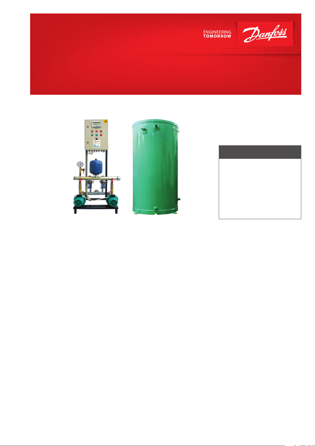
MAKE UP LINE Substations
A high performance system for make up, connecting to the secondary side of heating circuits
FEATURES AND BENEFITS
• Protection of the heating
circuit at overpressure
• Pressure maintaining in heating
system in very strict limits
• Controlled lling up of atmospheric
tank and of the heating circuit
• Short delivery time, easy to
install, minimal location site
Application
The Make Up Line is a range of systems
mounted on the secondary side (on
the interior building circuit) of district
heating systems or thermal plants with
maximum temperature of 115 °C and
PN 6 / PN 10. This system is suitable for
maintaining between an overpressure
given by water dilatation and an under
pressure limit given by loses of water
from dierent reasons in secondary
heating circuit. The dimensioning of
components in size and type is done
with a calculation method developed
by Schmidt-Bretten, member of Danfoss
Group.
Function
The Make Up system has the function to
discharge the soft water into an atmospheric tank via pressure relief valve(s) if
the heating circuit develops a pressure
value over the maximum set value or
has the function to ll up the heating
installation circuit via Make Up pump(s)
if the pressure decreases below the minimum set value. The volume of lling up
water or the leakage water from heating
circuit is automatically replaced in water
tank via solenoid valve.
Also, the system is able to protect the
pump in case of water lack, can assure
a sequential start of pumps, is able to
stop functioning pumps in case of pipe
breaking, can make automate switching on the second pump in case of failure function of the rst, assures the permanent monitoring of the water level
in the atmospheric tank (minimum,
normal and maximum) and assures the
ltering of water.
The entire system has an electric and
control panel connected to a pressure sensor and two level switches,
and function of received values commands the excess pressure valve(s), the
pump(s) or the solenoid valve opening/
closing.
Models
The Make Up system is available for
a wide range of standardized heating capacities between 500 kW and
8000 kW and for static pressures between 15 mwc and 60 mwc.
It has to be emphasized that this system is designed as an ecient two in
one pressure controller where control
is made automatic.
For all usually requests and for the
easier way of choosing the adequate
equipment, our specialists come with
standard solutions as shown in the
examples of the Make Up standard
range table. Although, other tailored
made equipment may be available on
demand.
Construction and installation
The pressure sensor, the closed pressure vessel, the level switches and
manometers are standard given for all
Make Up usually models. The pumps
are made of stainless steel. The atmospheric tank is made of steel. The
system equipment as valves, check
valves, strainers are made of brass.
The pipes of the system are made of
steel. The connections are made by
ange with gaskets, external and internal thread according to diameter.
In the construction can be integrated
optional modules for communications
via standardized RS485.
The MAKE UP LINE is delivered as
aunitary system, ready to be installed.
districtenergy.danfoss.com
Page 2
VD1
V1.1
VD2
PA1
V1.2
CV1
P
M
VTM
V2.1
V2.2
CV2
PA2 WTL
EVM
ELP
VA
FA
800 mm
800 mm
H
h
R1
WT
ELP
PA1
VTM
VD1
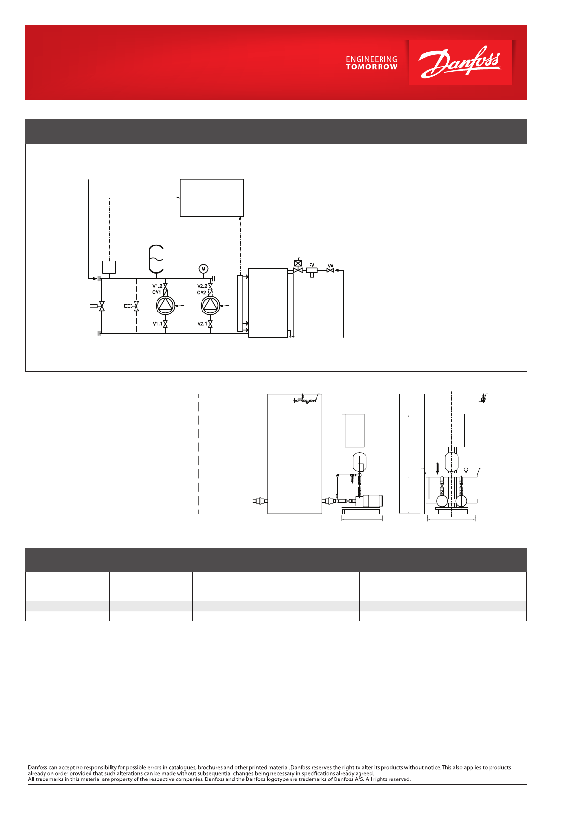
CIRCUIT DIAGRAM – EXAMPLE OF MAKE UP SYSTEM
R1 (R2): heating installation connection
Technical parameters:
Nominal pressure: PN 6 / PN 10
Maximum temperature: T
=115 °C
max
Make up source
Supply temperature: T
Nominal pressure: PN 6 / PN 10
max
= 80 °C
Electrical supply: 3~400 V /50Hz
PA1 (PA2) Make Up pump – one or two pieces
VD1 (VD2) Pressure relief valve
(pressure relief controller)
– one or two pieces
EVM Solenoid valve
P Pressure sensor
L Level switches
ELP Electric and control panel
V1 (V2) Shut o valve – pump circuit
VA Shut o valve – ll-up circuit
CV1 (CV2) Check valve
FA Strainer
M Manometer
WT Atmospheric water tank
VTM Closed pressure vessel
(against pressure shocks)
R3: soft water connection
R3: soft water connection
R3
(R2): heating
installation
connection
WT
additional
MAKE UP LINE (EXAMPLES):
Substation
type
EXP 203 2200 2 25 2 × 0,55 1 × 1000
EXP 405 4200 5 38 2 × 0,55 1 × 3500
EXP 805 6900 9 44 2 × 1,85 2 × 3000
SBT · Sos. Oltenitei no 208 · Popesti-Leordeni 077160 · Ilfov · România
Tel.: +4031 222 20 10 · Fax: +4031 222 22 99 · secretariat@schmidt.ro · www.schmidt.ro
© Danfoss | DHS-SRMT/ PL | 2016 . 02
Heating capacity
[kW]
Flow rate / one pump
[m3/h]
Static pressure
[mwc]
Electrical power
[kW]
Expansion tank pieces ×
volume, liters
VL.EH.E2.02
 Loading...