

Danfoss MAGFLO MAG 1100, MAGFLO MAG 3100, MAGFLO MAG 5000, MAGFLO MAG 6000, MAGFLO MAG 5100 W Handbook
Page 1
SAP No. 521H0879
DKFD.PS.027.W3.22
Handbook
MAGFLO
â
Electromagnetic flowmeters
Sensor types MAG 1100, MAG 3100, MAG 5100 W
Signal converter types MAG 5000, MAG 6000
[ ]
FLOW DIVISION - SIMPLY BETTER
Page 2
MAGFLO
Danfoss range of electromagnetic flowmeters
2
MAG 5000 MAG 6000
Outputs 1 current output 1 current output
1digital output 1digital output
1 relay output 1 relay output
Flow direction Uni/bidirectional Uni/bidirectional
Communication Optional Add-on modules
HART
HART, DeviceNet, Profibus DP,
Profibus PA, CANopen
Display 3 lines 3 lines
20 characters 20 characters
(optional without display) (optional without display)
Meter uncertainty ±0.5% of rate ±0.25% of rate
Enclosure NEMA 2, NEMA 4X, NEMA 6 NEMA 2, NEMA 4X, NEMA 6
Custody transfer PTB PTB
approval (cold water) OIML R75
OIML R117
Ex-version [EEx ia/ib] IIB
Safety barrier intrinsically safe
Power supply 12-24 V a.c./d.c. 12-24 V a.c./d.c.
115-230 V a.c. 115-230 V a.c.
Batch No Yes
Approvals ULc general purpose ULc general purpose
FM Class 1, division 2 FM Class 1, division 2
MAG 1100 MAG 1100 MAG 3100 MAG 3100 W MAG 5100 W
FOOD
Size [inch]
1
/4" - 4"
3
/8" - 4"
1
/2" - 78" 1" - 48" 1" - 48"
Connection Flangeless Weld-in adapter, Flange Flange Flange
(Wafer) clamp adapter,
thread adapter
Pressure [psi] 600 600 1500 600 600
Temperature [
°°
°°
°F] 0 to 400 −20 to 300 −40 to 350 −20 to 200 −20 to 200
Liner Ceramic (Al2 O3) Ceramic (Al2 O3) Neoprene, EPDM, Neoprene and 1" - 1½" &
PFA PFA Teflon (PTFE), EPDM 14" - 48"
Ebonite, hard elastomer
Linatex
2" - 12"
composite elastomer
Electrodes Platinum Platinum AISI 316 Ti, AISI 316 Ti AISI 316 Ti,
Hastelloy C276 Hastelloy C276 Hastelloy C, Grounding electrode Grounding electrode
Platinum/Iridium,
Titanium,
Tantalum
Grounding electrode
Enclosure NEMA 4X & NEMA 6
Ex-version EEx ia/ib IIB T4-T6 EEx ia/ib IIB T4-T6
Houzandous area intrinsically safe intrinsically safe
Approvals FM Class 1, division 2, WRc, NSF
WRc, NSF
Page 3

MAGFLO
â
3
Contents
1.1 Product intro duct ion ............................................................................................................................................................. 4
1.2 Mode of op eration ................................................................................................................................................................ 5
2.1 Sensor MAG 1100 and MAG 1100 Ex ............................................................................................................................... 6
2.2 Sensor MAG 1100 FOOD .................................................................................................................................................... 7
2.3 Sensor MAG 3100, MAG 3100 Ex and MAG 3100 W ................................................................................................... 8-9
2.4 Sensor MAG 5100 W ......................................................................................................................................................... 10
2.5 .1 Signal converter MAG 5000 (1/4" to 48") ......................................................................................................................... 11
2.5 .2 Signal converter MAG 6000 (1/4" to 78") ......................................................................................................................... 12
2.5 .3 Safety barrier (ia/ib) for sizes up to 12'’ ......................................................................................................................... 13
2.5 .4 Cleaning unit ....................................................................................................................................................................... 13
2.6 Meter uncertai nty ............................................................................................................................................................... 14
2.7 Output characteristics MAG 5000 and MAG 6000 ......................................................................................................... 15
2.8 .1 Sensor cables and conduc tivity of medium .................................................................................................................... 16
2.8 .2 Minimum accept data for cable ......................................................................................................................................... 16
2.9 HARTâ communication add-on module ............................................................................................................................ 16
2.1 0 Cable specificatio ns (Supplied by Danfoss ) ................................................................................................................... 16
3.1 Sizing table (1/4" to 78") .................................................................................................................................................... 17
3.2 .1 Minimum conduct ivity ......................................................................................................................................................... 18
3.2 .2 Liner selectio n guide .......................................................................................................................................................... 18
3.2 .3 Elect rode select ion guide .................................................................................................................................................. 18
3.3 Inst alla tion conditi ons .................................................................................................................................................. 1 8-21
3.4 Cleaning unit ....................................................................................................................................................................... 22
3.5 Custo dy transfer approva l ................................................................................................................................................. 23
3.6 Signal converter 5000 CT, MAG 6000 CT Sealing ......................................................................................................... 23
3.7 Ex installat ions ................................................................................................................................................................... 24
4.1 Sensor MAG 1100 .............................................................................................................................................................. 25
4.2 Sensor MAG 1100 FOOD ............................................................................................................................................ 26-27
4.3 Sensor MAG 5100 W ................................................................................................................................................... 28-29
4.4 Sensor MAG 3100 and MAG 3100 W ......................................................................................................................... 3 0-31
4.5 Signa l converte r ........................................................................................................................................................... 31-33
5.1 Potent ial equalizat ion (Groundin g) ................................................................................................................................... 34
5.2 Inlet protection MAG 3100 ................................................................................................................................................ 35
5.3 Cathod ic protected piping ................................................................................................................................................. 35
6.1 Integral mount installation MAG 5000 and MAG 6000 ............................................................................................. 36 -37
6.2 .1 Add-on modules (MAG 6000 only) .................................................................................................................................... 38
6.2 .2 Remote installat ion (Sensor end) ..................................................................................................................................... 38
6.2 .3 Remote installation (Wall mount) ................................................................................................................................ 39-40
6.2 .4 Remote insta llation (Rack mount) ..................................................................................................................................... 41
6.2 .5 Add-on modules (MAG 6000 only) .................................................................................................................................... 42
6.2 .6 Inst allatio n using wall mount ing kit ................................................................................................................................. 43
6.2 .7 Install ati on using front of panel mountin g kit ............................................................................................................... 44
6.2 .8 Ins tall ati on usin g back of panel moun tin g kit ............................................................................................................... 45
6.3 Signal conv erter with safety barrier ................................................................................................................................. 46
6.4 Signal converter with cleaning unit .................................................................................................................................. 47
7.1 Signal converter MAG 5000 and MAG 6000 connection diagram ................................................................................. 48
7.2 Wiring diagram for signal converter and sensor ............................................................................................................. 49
7.2 .1 Inte gral insta llation ............................................................................................................................................................. 49
7.2 .2 Remote installation wall mount NEMA 6 enclosure ......................................................................................................... 49
7.2 .3 Rack mount NEMA 2 enclosure ........................................................................................................................................ 50
7.2 .4 Wall mount NEMA 4X enclosure ....................................................................................................................................... 50
7.2 .5 Rack mount with safety barrier NEMA 2 EEx (ia/ib) up to 12'' ..................................................................................... 50
7.2 .6 Wall mount with safety barrier NEMA 6 EEx (ia/ib) up to 12'' ...................................................................................... 51
7.2 .7 Rack mount NEMA 2 with cleaning unit.......................................................................................................................... 51
7.2 .8 Wall mount NEMA 6 with cleaning unit ............................................................................................................................. 51
8.1 Keypad and disp lay layout ................................................................................................................................................ 52
8.2 Menu build-up ..................................................................................................................................................................... 53
8.2 .1 Passwor d ............................................................................................................................................................................. 53
8.3 .1 MAG 5000 and MAG 6000................................................................................................................................................. 54
8.3 .2 MAG 6000 CT ..................................................................................................................................................................... 55
8.4 .1 Bas ic settings ..................................................................................................................................................................... 56
8.4 .2 Outpu ts ............................................................................................................................................................................... 57
8.4 .3 Digital and relay outputs .................................................................................................................................................... 57
8.4 .4 Relay output ........................................................................................................................................................................ 58
8.4 .5 External input ..................................................................................................................................................................... 58
8.4 .6 Sen sor characteri sti cs ...................................................................................................................................................... 59
8.4 .7 Reset mode ......................................................................................................................................................................... 59
8.4 .8 Service mode ...................................................................................................................................................................... 60
8.4 .9 Operat or menu setup ......................................................................................................................................................... 61
8.4 .10 Product identity (read only) ............................................................................................................................................... 62
8.4 .11 Change password ............................................................................................................................................................... 62
8.4 .12 Language mode .................................................................................................................................................................. 63
8.4 .13 HART
â
communication MAG 5000 HART or as add-on module .................................................................................... 63
8.5 .1 Flow rate .............................................................................................................................................................................. 64
8.5 .2 Totalizer ............................................................................................................................................................................... 64
8.5 .3 Ba tch ................................................................................................................................................................................... 64
8.6 .1 Factory setting s/avail able settings .................................................................................................................................. 65
8.6 .2 Dimension dependent factory settings MAG 50 00 and MAG 6000 .............................................................................. 66
8.6 .3 Dimens ion dependent batc h and pulse output settings ................................................................................................. 66
8.6 .4 MAG 6000 CT settings ...................................................................................................................................................... 67
8.7 .1 Error handling ..................................................................................................................................................................... 68
8.7 .2 List of error numbers ......................................................................................................................................................... 69
9.1 Converter check list ........................................................................................................................................................... 70
9.2 Trouble shooting MAG 5000 and MAG 6000 ................................................................................................................... 71
9.3 Check list MAG senso r ...................................................................................................................................................... 72
9.4 Coil resistan ce table .......................................................................................................................................................... 73
10. 1 Sensor MAG 1100 ........................................................................................................................................................ 7 4-75
10. 2 Adapter, MAG 1100 FOOD (contains 2 adapt ers, 2 clamp rings and 2 gaskets) ....................................................... 75
10. 3 Sensor MAG 3100 and MAG 3100 Ex ....................................................................................................................... 76-77
10. 4 Sensor MAG 3100 W ......................................................................................................................................................... 78
10. 5 Sensor MAG 5100 W ......................................................................................................................................................... 79
10. 6 Signa l converte r ................................................................................................................................................................. 80
10. 7 Signal converter rack mount ............................................................................................................................................. 81
10. 8 Acc es so rie s ........................................................................................................................................................................ 82
10. 9 Calibration ........................................................................................................................................................................... 83
2. Specifications
1. Product introduction
3. Product selection guidelines
4. Dimensions and weight
6. Installation of signal
conv erter
5. Installation of sensor
7. Electrical connection
8. Start-up & programming
10. Ordering
9. Serv ic e
Page 4
MAGFLO
â
4
1.1
Product introduction
1. Product introduction
MAGFLOâ electromagnetic flowmeters offer reliable, precise and inexpensive flow measurement on all electrically conductive liquids. Typical applications are found in all industries. E.g.:
• Water sector: Potable water, treatment of chemicals, waste water and sludge.
• Food sector: Dairy products, beer, wine, soft-drinks and fruit juices.
• Chemical sector: Detergents, pharmaceuticals, acids and alkalies.
• Other sectors: HVAC, paper pulp and mining slurries.
MAGFLOâ electromagnetic flowmeters are characterised by simplicity:
Þ Simple to install
Þ Simple to commission
Þ Simple to operate
Þ Simple to maintain
MAGFLO
â
electromagnetic flowmeters are manufactured by Danfoss A/S, Flow Division - one of
the worlds leading makers of flowmeters.
All MAGFLOâ electromagnetic flowmeters feature a unique SENSORPROM® memory unit which
stores sensor calibration data and signal converter settings for the lifetime of the product.
At commissioning the flowmeter commences measurement without any initial programming.
The factory settings matching the sensor are stored
in the SENSORPROM® unit. Also customer specified
settings are downloaded to the SENSORPROM
®
unit. Should the signal converter be replaced, the
new converter will upload all previous settings and
resume measurement without any need for reprogramming.
Furthermore, the "fingerprint" used in connection
with the Danfoss Verificator is stored during the sensor calibration.
The Danfoss Verificator can verify the accuracy of
the flowmeter while still installed years after the
initial calibration.
USM II "Plug & Play" add-on communication modules.
USM II - the Universal Signal Module with "Plug &
Play" simpl ic it y makes it e asy to access and
integrate the flow measurement with almost any
system. It ensures the flowmeter will be easy to
upgrade to new communication platforms in the
future, too.
Page 5

MAGFLO
â
5
1. Product introduction
1.2
Mode of operation
Ui = When an electrical conductor of length L is moved at velocity v, perpendicular to the lines of
flux through a magnetic field of strength B, the voltage Ui is induced at the ends of the conductor
Ui = L x B x v
Ui= Induced voltage
L = Conductor length = Inner pipe diameter = k
1
B = Magnetic field strength = k
2
v = Velocity of conductor (media)
k = k1 x k
2
Ui = k x v, the electrode signal is directly proportional to the fluid velocity
SENSOR (Flow tube)
The sensor converts the flow into an electrical voltage (U
i
) proportional to the velocity of the flow.
The sensor is built up of a stainless steel pipe, 2 coils, electrodes, an isolating liner, housing and
where applicable, connecting flanges.
SIGNAL CONVERTER
The signal converter consists of a number of function blocks which convert the sensor voltage into
flow readings.
Power supply
2 different types of power supply are available. A 12 - 24 V a.c./d.c. and a 115 - 230 V a.c. switch
mode type.
Coil current module generates a pulsating magnetizing current that drives the coils in the sensor.
The current is permanently monitored and corrected. Errors or cable faults are registered by the selfmonitoring circuit.
Input circuit amplifies the flow proportional signal from the electrodes. The input impedance is
extremely high: >10
14
W which allows flow measurements on fluids with conductivities as low as
1 mS/cm. Measuring errors due to cable capacitance are eliminated due to active cable screening.
Digital signal processor converts the analog flow signal to a digital signal and suppresses
electrode noise through a digital filter. Inaccuracies in the signal converter as a result of long-term
drift and temperature drift are monitored and continuously compensated for via the self-monitoring
circuit. The analog to digital conversion takes place in an ultra low noise ASIC with 23 bit signal
resolution. This has eliminated the need for range switching. The dynamic range of the signal
converter is therefore unsurpassed with a turn down ratio of minimum 3000:1.
CAN communication
The signal converter operates internal via an internal CAN communication bus. Signals are
transferred to/from a signal conditioner to the display module, internal/external option modules and
the dialog module.
Dialog module
The display unit consists of a 3-line display and a 6-key keypad. The display shows a flow rate or
a totalizer value as a primary reading.
Output module converts flow data to an analog, a digital and a relay output. The outputs are
galvanically isolated and can be individually set to suit a particular application.
The flow measuring principle is based on Faraday’s law of electromagnetic induction. The flowmeter
consists of a sensor type MAG 1100, 3100 or 5100 W and a signal converter type MAG 5000 or 6000.
Page 6
MAGFLO
Specif ications
6
2. Specifications MAG 1100 and MAG 1100 Ex
Type Flangeless sensor (Wafer)
Nominal size
1
/4", 3/8", 1/2", 1", 11/2", 2", 3", 4"
3
/8", 1/2", 1", 11/2", 2", 3", 4"
1
/4", 3/8", 1/2", 1", 11/2", 2", 3", 4"
Operating pressure
1
/4"-21/2": 600 psi, 3": 560 psi,
1
/4"-21/2": 600 psi, 3": 560 psi,
4": 450 psi 300 psi 4": 450 psi
Vacuu m
1.5 × 10⁻⁵ psi 0.3 psi 1.5 × 10⁻⁵ psi
Temperature of
PFA
−20°F to +265°F
medium
Ceramic
0°F to +300°F −5°F to +250°F
High temperature version
0°F to +400°F Suitable for steam sterilization at 300°F
Temperature shock (Duration > 1 min.): Max. ±210° F momentarily (Duration > 1 min.):
(Ceramic liner)
1
/4", 3/8", 1/2", 1":
1
/4", 3/8", 1/2", 1":
Max. ∆T ≤ 60°F/min. Max. ∆ T ≤ 60°F/min.
1
1
/2", 2", 21/2": Max. ∆T ≤ 50°F/min. 11/2", 2", 21/2" : Max. ∆T ≤ 50°F/min.
3", 4" : Max. ∆T ≤ 40°F/min. 3", 4" : Max. ∆T ≤ 40°F/min.
(Duration ≤ 1 min., (Duration ≤ 1 min.,
followed by 10 min. rest): followed by 10 min. rest):
1
/4", 3/8", 1/2", 1": Max. ∆T ≤ 175°F
1
/4", 3/8", 1/2", 1": Max. ∆T ≤ 175°F
1
1
/2", 2", 21/2": Max. ∆T ≤ 160°F 11/2", 2", 21/2": Max. ∆T ≤ 160°F
3", 4": Max. ∆T ≤ 140°F 3", 4": Max. ∆T ≤ 140°F
Ambient temperature Remote mount signal converter: −40°F to +210°F
Integral mount signal converter: −5°F to +120°F
Liner Aluminum oxide Al2O3 (ceramics) Reinforced PFA (Teflon) Aluminum oxide Al2O3 (ceramics)
Elec tro des Platinum with gold/titanium brazing Hastelloy C-276 Platinum with gold/titanium brazing
alloy alloy
Enclosure Stainless steel AISI 316L (1.4404) Stainless steel AISI 316 (1.4436) Stainless steel AISI 316L (1.4404)
Stainless steel AISI 316 (1.4436)
Terminal box
Standard
Fiberglass-reinforced polyamide Fiberglass-reinforced polyamide Stainless steel AISI 316L (1.4404)
(Remote installation only)
High temp.
Stainless steel AISI 316 (1.4436) Stainless steel AISI 316L (1.4404)
Studs & nuts Stainless steel AISI 304 (1.4301) Stainless steel AISI 304 (1.4301)
Number and size to DIN 2501 Number and size to DIN 2501
Mating flanges DIN 2501 (150-600 psi), ANSI B16.5,
class 150 and 300 or equivalent
To DIN 2501 (150-600 psi),
ANSI B16.5,
class 150 and 300 or equivalent
Option
1/4'' & 3/8'': 1/2'' NPT threaded adaptor
Gaskets
Standard
EPDM (max. 300°F, 600 psi) EPDM (max. 300°F, 600 psi)
Option
Graphite (max. 390°F, 600 psi) Graphite (max. 390°F, 600 psi)
Option
PTFE (max. 210°F, 300 psi) PTFE (max. 265°F, 300 psi)
Cable entries 4 pcs. PG 13.5
Enclosure rating
Standard
NEMA 4X / 6 (3 ft. submersion for 30 min)
Option
NEMA 6P (30 ft. continuous submersion)
Mechanical load (vibration) 18-1000 Hz random, 3.17 G rms in all directions to EN 60068-2-36 18-1000 Hz random in all directions
to EN 60068-2-36
Sensor: 3.17 G/
Integral mount Ex-d: 1.14 G
Test pressure 1200 psi (2 × nominal) 600 psi (2 × nominal) 1200 psi (2 × nominal)
Ex approvals EEx [ia/ib] IIB T4-T6/
DEMKO, No. 97D.121909X
Excitation frequency
1
/4" - 21/2": 15 Hz
3
/8" - 21/2": 15 Hz
1
/4" - 21/2": 15 Hz
programmable 3", 4": 7.5 Hz 3", 4": 7.5 Hz 3", 4": 7.5 Hz
2. Specifications
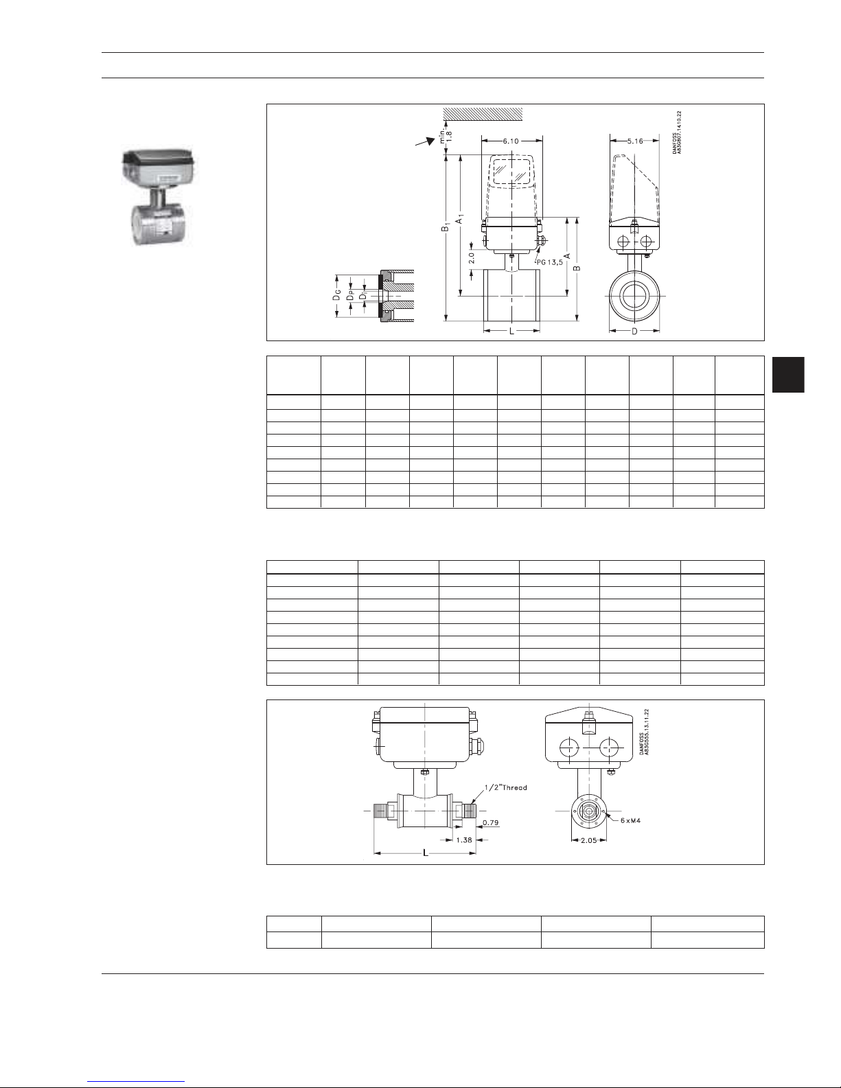
2.1 Sensor MAG 1100 and MAG 1100 Ex
MAG 1100 Ceramic MAG 1100 PFA
MAG 1100 Ex
Page 7
MAGFLO
7
Specif ications
Adapters Stainless steel AISI 316 Pressure
Pipe connection/ Adapter for direct welding into pipe:
Ope rating
Tri-Clover
ISO 2037, DIN 11850, SMS 3008, BS 4825-1
pressure
3
/8", 1/2", 1", 11/2", 2", 3" 600 psi
4" 350 psi
Clamp adapter:
Tri-Clamp
ISO 2852, DIN 32676, SMS 3016, BS 4825-3
3
/8", 1/2", 1", 11/2", 2" 200 psi
21/2", 3", 4" 150 psi
Thread adapter:
DIN 11851:
3
/8", 1/2", 1", 11/2" 600 psi
2", 21/2", 3", 4" 350 psi
ISO 2853, SS 3351, BS 4825-4:3/8", 1/2", 1", 11/2", 2", 3", 4" 200 psi
SMS 1145: 1", 11/2", 2", 21/2", 3" 80 psi
Gas ke t
Standard
EPDM (ethylene, propylene rubber) (− 5 °F to 300 °F)
Option
NBR (nitrile butadiene rubber) (−5 °F to 210 °F)
Material Stainless steel AISI 304, ISO 2852
Type Hygienic sensor
Nominal size
3
/8", 1/2", 1", 11/2", 2", 3", 4"
Process connection Hygienic adapters available for:
♦ Direct welding in ♦ Clamp fitting ♦ Threaded fitting
Operating pressure
3
/8"-21/2": 600 psi, 3": 560 psi, 4": 450 psi 300 psi
Vacuum
1.5 × 10⁻⁵ psi 0.3 psi
Temperature of medium 0°F to +300°F − 20°F to +270°F
Suitable for steam sterilization Suitable for steam sterilization at 300°F
Temperature shock (Duration > 1 min.): Max. ±212°F momentarily
3
/8", 1/2", 1" Max. ∆T ≤ 60°F/min.
11/2", 2", 21/2" Max. ∆T ≤ 50°F/min.
3", 4" Max. ∆T ≤ 40°F/min.
(Duration ≤ 1 min., followed by 10 min. rest):
3
/8", 1/2", 1" Max. ∆T ≤ 175°F
11/2", 2", 21/2" Max. ∆T ≤ 160°F
3", 4" Max. ∆T ≤ 140°F
Ambient temperature Remote mount signal converter: −40°F to +210°F Remote mount signal converter: −40°F to +210° F
Integral mount signal converter: − 5°F to +120°F Integral mount signal converter: −5° F to +120°F
Liner Aluminum oxide Al2O3 (ceramic) Reinforced PFA (Teflon)
Electrodes Platinum with gold/titanium brazing alloy Hastelloy C-276
Enclosure Stainless steel AISI 316L (1.4404) Stainless steel AISI 316L (1.4404)
Terminal box
Standard
Fiberglass-reinforced polyamide Fiberglass-reinforced polyamide
(Remote installation only)
Option
Stainless steel AISI 316 (1.4436) Stainless steel AISI 316 (1.4436)
Cable entries 4 pcs. PG 13.5 4 pcs. PG 13.5
Enclosure rating
Standard
NEMA 4X / 6 (3 ft. submersion for 30 min) NEMA 4X / 6 (3 ft. submersion for 30 min)
Option
NEMA 6P (30 ft. continuous submersion) NEMA 6P (30 ft. continuous submersion)
Mechanical load (vibration) 18-1000 Hz random, 3.17 G rms in all directions, 18-1000 Hz random, 3.17 G rms in all directions,
to EN 60068-2-36 to EN 60068-2-36
Test pressure 1200 psi (2 × nominal) 600 psi (2 × nominal)
Approvals 3A, EHEDG 3A
Excitation frequency
3
/8" - 21/2": 15 Hz
3
/8" - 21/2": 15 Hz
programmable 3", 4": 7.5 Hz 3", 4": 7.5 Hz
2.2 Sensor MAG 1100 FOOD
MAG 1100 FOOD MAG 1100 FOOD PFA
2. Specifications MAG 1100 FOOD
Accessories
MAG 1100 FOOD
Note
It is always a system so please state system max. pressure and not MAG 1100 or adapter.
Page 8
MAGFLO
â
Specif ications
8
Type Sensor with flanges Sensor with flanges Sensor with flanges
Nominal size
1
/2" - 78"
1
/2" - 12" 1" - 48"
Temperature of medium Temperature classification
Liner: T3 + T4 T5 T6
Neoprene (standard) 30 to 160°F 30 to 160°F 30 to 160°F 30 to 160°F 30 to 160°F
EPDM1) -20 to 200°F -20 to 200°F -20 to 190°F -20 to 170°F -20 to 200°F
Linatexâ rubber -40 to 160°F2) 0 to 160°F 0 to 160°F 0 to 160°F
Ebonite1) 30 to 200°F 30 to 200°F 30 to 190°F 30 to 170°F
PTFE 0 to 210°F 0 to 210°F 0 to 190°F 0 to 170°F
PTFE high temperature 0 to 350°F
Ambient temperature
Remote mount signal converter -40°F to 210°F 0°F to 105°F -40°F to 210°F
Integral mount signal converter 0°F to 120°F 0°F to 105°F 0°F to 120°F
Operating pressure3) [abs.psi]
Liner:
Neoprene 0.15 to 1500 psi 0.15 to 1500 psi 0.15 to 600 psi
EPDM 0.15 to 600 psi 0.15 to 600 psi 0.15 to 600 psi
Natural rubber & Linatexâ0.15 to 600 psi 0.15 to 600 psi
Ebonite 0.15 to 1500 psi 0.15 to 1500 psi
PTFE teflon:
1
/2" - 24" Max. 210°F: 4.5 to 750 psi 4.5 to 600 psi
1
/2" - 12" Max. 350°F: 9.0 to 750 psi
Excitation frequency
1
/2" - 21/2": 15 Hz
1
/2" - 21/2": 7.5 Hz All sizes: 3.75 Hz
3" - 6": 7.5 Hz 3"/4": 3.75 Hz
8" - 48": 3.75 Hz 5" - 12": 1.875 Hz
54" - 78": 1.875 Hz 14" - 48": 3.75 Hz
Enclosure rating
Standard
NEMA 4X / 6 (3 ft. submersion for 30 min)
Option
NEMA 6P (30 ft. continuous submersion)
Cable entries 4 pcs. PG 13.5 - 2 others available
Mechanical load 18-1000 Hz random, 3.17 G rms in all directions, to EN 60068-2-36
Test pressure 1.5 ´ nominal pressure
Approvals FM Class 1, division 2
2. Specifications MAG 3100, MAG 3100 Ex and MAG 3100 W
2.3 Sensor MAG 3100, MAG 3100 Ex and MAG 3100 W
MAG 3100 MAG 3100 Ex MAG 3100 W
1
) With WRC and NSF (Water Research Council, UK) approval
2
) For temperature below -5°F AISI 304 or 316 flanges must be used
3
) Maximum operating pressure decreases with increasing operating temperature and with stainless steel flanges
Page 9
MAGFLO
â
9
Specif ications
2.3 Sensor MAG 3100, MAG 3100 Ex and MAG 3100 W
(continued)
2. Specifications MAG 3100, MAG 3100 Ex and MAG 3100 W
Fla ng es
Standard
DN 15-50: 600 psi DN 25-50: 600 psi
EN 1092-1:20011) DN 65-150: 200 psi DN 65-150: 200 psi
Rased face DN 200-1000: 150 psi DN 200-1200: 150 psi
DN 1100 -2000: 80 psi
Option
DN 65-1000: 80 psi DN 200-600: 200 psi
DN 1200-2000: 150 psi
DN 200-2000: 200 psi
DN 200-600: 350 psi
DN 65-600: 600 psi
DN 50-400 945 psi (DIN 2636)
DN 25-350 150 psi (DIN 2637)
ANSI B 16.5 3/4"-24": Class 150 (290 psi) 3/4"-24": Class 150 (290 psi)
(~BS 1560) 3/4"-24": Class 300 (725 psi)
AS 2129 3/4"-48": Table D/E
AS 4087 Class 14 (DN 50-1200, 200 psi)
Class 21 (DN 50-600, 300 psi)
Class 35 (DN 50-600, 500 psi)
AWWA C-207 28"-78": Class D (145 psi) 28"-48": Class D (145 psi)
Electrodes
Standard
AISI 316 Ti (1.4571) AISI 316 Ti (1.4571)
Option
Hastelloy C-276, Platinum / Iridium, Titanium,
AISI 316 Ti Ceramic Coated, Tantalum
Grounding electrodes
Standard
As measuring electrodes (except PTFE) AISI 316 Ti (1.4571)
Measuring pipe
Standard
AISI 304 (1.4301) AISI 304 (1.4301)
Option
AISI 316L (1.4404)
Flange and
Standard
Carbon steel Carbon steel
housing material Corrosion-resistant two-component coating (min. 150 mm) Corrosion-resistant two-compo-
nent coating (min. 150 mm)
Option
AISI 304 (1.4301) flanges and carbon steel housing.
Coating as above
Option
AISI 316 L (1.4404) flanges and housing
Ex-approval
Remote mount
1
/2" - 12" EEx [ia/ib] IIB T4-T6
Approvals FM Class 1, division 2 FM Class 1, division 2
MAG 3100 MAG 3100 Ex MAG 3100 W
1
) EN 1092-1, DIN 2501 & BS 4504 have the same mating dimensions
Page 10
MAGFLO
â
Specif ications
10
Type Sensor with flanges
Des ig n Straight Coned down 1 pipe size Straight
Nominal size
inch
1" - 1½" 2" - 12" 14" - 48"
Liner Hard elastomer Composite elastomer Hard elastomer
(hard rubber) (hard & soft rubber) (hard rubber)
Liner approvals WRc, NSF WRc, NSF WRc, NSF
Medium temperature 25 to 200°F
Ambient temperature
Remote signal converter -40 to 200°F
Compact signal converter -5 to 125°F
Operating pressure 0.15 to 580 psi 0.45 to 300 psi 0.15 to 200 psi
Excitation frequency 12.5 Hz 2-2½": 12.5 Hz 3.125 Hz
3-6": 6.25 Hz
8-12": 3.125 Hz
Enclosure rating
Standard
NEMA 4X / 6 (3 ft. submersion for 30 min)
Option
NEMA 6P (30 ft. continuous submersion)
Cable entries 4 Pg 13.5
Mechanical load 18-1000 Hz random, 3.17 G rms in all directions to EN 60068-2-36
Test pressure 1.5 ´ nominal pressure
Fla ng es
EN 1092-1
Standard
600 psi 2-6": 200 psi 150 psi
8-12": 150 psi
Option
8-12": 200 psi 200 psi
ANSI B16.5
Standard
Class 150 lb Class 150 lb 14"-24": Class 150 lb
AWWA C-207 Standard 28"-48": Class D
Pressure drop at 3 m/sec. As straight pipe Max. 0.35 psi As straight pipe
Electrodes AISI 316 Ti (1.4571)
PE/grounding electrodes
Standard
AISI 316 Ti (1.4571)
Measuring pipe/meter body AISI 304 (1.4301) Composite elastomer AISI 304 (1.4301)
Fla ng es Carbon steel
Housin g Carbon steel
Surface finish Two component epoxy Polyester powder coat Two component epoxy
min. 150 microns min. 100 microns min. 150 microns
Color RAL 7035 pale grey
Approvals
Conforms to
WRc, NSF
1
) For sizes greater than 24" PED conformity is available as a cost added option, the basic unit will only carry the LVD (Low Voltage Directive)
and EMC approval.
2. Specifications MAG 5000 and MAG 5000 CT
2.4 Sensor MAG 5100 W
Page 11
MAGFLO
â
11
Specif ications
Current output
Active current 0-20 mA, 4-20 mA or 4-20 mA + alarm (Power supplied from flowmeter)
Load < 800 ohm
Time constant 0.1-30 sec. adjustable
Digital output
Fre quency 0-10 kHz, 50% duty cycle
Time constant 0.1-30 sec. adjustable
Active pulse 24 V d.c., 30 mA, 1 KW £ R
load
£ 10 KW, short-circuit-protected (Power supplied from flowmeter)
Passive pulse 3-30 V d.c., max. 110 mA, 200 W £ R
load
£ 10 KW (Powered from connected equipment)
Relay Time constant Changeover relay, time constant same as current time constant
Load 42 V a.c./2 A, 24 V d.c./1A
Digital input 11-30 V d.c., Ri = 4.4 KW
Activation time 50 msec.
Current I
11 V d.c.
= 2.5 mA, I
30 V d.c.
= 7 mA
Functions Flowrate, 2 totalizers, low flow cut-off, empty pipe cut-off, flow direction, error system, operating time,
uni/bidirectional flow, limit switches, pulse output, control for cleaning unit
Galvanic isolation All inputs and outputs are galvanically isolated
Cu t-o ff Low flow 0-9.9% of maximum flow
Empty pipe Detection of empty pipe 1)
Totalizer Two eight-digit counters for forward, net or reverse flow
Display Background illumination with alphanumerical text, 3 × 20 characters to indicate flowrate, totalized
values, settings and faults
Reverse flow indicated by negative sign
Time constant Time constant as current output time constant
Zero point adjustment Automatic
Electrode input impedance > 1 x 10¹⁴ W
Excitation frequency Sensor size depending pulsating d.c. current (125 mA)
Ambient temperature Display version during operation: -5 to 120°F
Blind version during operation: -5 to 140°F
During storage: -40 to 160°F (Relative humidity max 95%)
Custody transfer approval PTB
MAG 5000 CT (cold water)
Com municatio n
Standard
Without serial communication
Optional
HART
â
Integral mount
Enclosure material Fiberglass-reinforced polyamide
Enclosure rating NEMA 4X / 6 (3 ft. submersion for 30 min)
Mecanical load 18-1000 Hz random, 3.17 G rms in all directions to EN 60068-2-36
Rack mount
Enclosure material Standard rack mount of aluminum/steel (DIN 41494)
Width: 4.75 inch
Height: 5.25 inch
Enclosure rating NEMA 2
Mechanical load Version: 1 G, 1-800 Hz sinusoidal in all directions to EN 60068-2-36
EMC performance Emission: EN 50081-1 (Light industry)
Immunity: EN 50082-2 (Industry)
Power supply 115-230 V a.c. +10% to -15%, 50-60 Hz
11-30 V d.c. or 11-24 V a.c.
Power consumption 230 V a.c.: 9 VA
24 V d.c.: 9 W, IN = 380 mA, start-up peak current = 8 A (30 msec.)
12 V d.c.: 11 W, IN = 920 mA start-up peak current = 4 A (250 msec.)
Approvals FM Class 1, division 2, ULc general purpose
1
) Special cable required in separate mounted installation
2. Specifications MAG 5000 and MAG 5000 CT
2.5.1 Signal converter MAG 5000 (1/4" to 48")
Accuracy 0.5%
6.221
99.19
Page 12
MAGFLO
â
Specif ications
12
Current output
Active current 0-20 mA, 4-20 mA or 4-20 mA + alarm (Power supplied from flowmeter)
Load < 800 ohm
Time constant 0.1-30 sec. adjustable
Digital output
Frequency 0-10 kHz, 50% duty cycle
Time constant 0.1-30 sec. adjustable
Active pulse 24 V d.c., 30 mA, 1 KW £ R
load
£ 10 KW, short-circuit-protected (Power supplied from flowmeter)
Passive pulse 3-30 V d.c., max. 110 mA, 200 W £ R
load
£ 10 KW (Powered from connected equipment)
Relay Time constant Changeover relay, time constant same as current time constant
Load 42 V a.c./2 A, 24 V d.c./1A
Digital input 11-30 V d.c., Ri = 4.4 KW
Activation time 50 msec.
Current I
11 V d.c.
= 2.5 mA, I
30 V d.c.
= 7 mA
Functions Flowrate, 2 totalizers, low flow cut-off, empty pipe cut-off, flow direction, error system, operating time,
uni/bidirectional flow, limit switches, pulse output, control for cleaning unit and batching
Galvanic isolation All inputs and outputs are galvanically isolated
Cu t-o ff Low flow 0-9.9% of maximum flow
Empty pipe Detection of empty pipe 1)
Totalizer Two eight-digit counters for forward, net or reverse flow
Display Background illumination with alphanumerical text, 3 × 20 characters to indicate flowrate, totalized
values, settings and faults
Reverse flow indicated by negative sign
Time constant Time constant as current output time constant
Zero point adjustment Automatic
Electrode input impedance > 1 x 10
14
W
Excitation frequency Sensor size depending pulsating d.c. current (125 mA)
Ambient temperature Display version during operation: -5 to 120°F
Blind version during operation: -5 to 140°F
During storage: -40 to 160°F (Relative humidity max 95%)
Custody transfer approval PTB DANAK OIML R75 DANAK OIML R117
MAG 6000 CT only (cold water) (hot water) (cold water/milk, beer etc.)
Com municatio n
Standard
Prepared for client mounted add-on modules
Optional
HART, Profibus PA, Profibus DP, CANopen, DeviceNet as add-on module
Integral mount
Enclosure material Fiberglass-reinforced polyamide
Enclosure rating NEMA 4X / 6 (3 ft. submersion for 30 min)
Mecanical load 18-1000 Hz random, 3.17 G rms in all directions to EN 60068-2-36
Rack mount
Enclosure material Standard rack mount of aluminum/steel (DIN 41494)
Width: 4.75 inch
Height: 5.25 inch
Enclosure rating NEMA 2
Mechanical load Version: 1 G, 1-800 Hz sinusoidal in all directions to EN 60068-2-36
EMC performance Emission: EN 50081-1 (Light industry)
Immunity: EN 50082-2 (Industry)
Power supply 115-230 V a.c. +10% to -15%, 50-60 Hz
11-30 V d.c. or 11-24 V a.c.
Power consumption 230 V a.c.: 9 VA
24 V d.c.: 9 W, IN = 380 mA, start-up peak current = 8A (30 msec.)
12 V d.c.: 11 W, IN = 920 mA, start-up peak current = 4A (250 msec.)
Approvals FM Class 1, division 2, ULc general purpose
1
) Special cable required in separate mounted installation
2. Specifications MAG 6000 and MAG 6000 CT
2.5.2 Signal converter MAG 6000 (1/4" to 78")
Accuracy 0.25% (0.5% for MAG 3100 W sensor)
6.221
99.19
Page 13
MAGFLO
â
13
Specif ications
2. Specifications Safety barrier & cleaning unit
Applic ation As combined unit with MAG 6000 only and MAG 1100 Ex/3100 Ex in the size
range 1/4" - 12"
Ex approval [EEx ia/ib] IIB
Cable parameter Group Capacity in mF Inductance in mH
Electrode cable IIB £ 31 £ 80
Coil cable IIB £ 0.5 £ 8
Ambient temperature During operation: -5 to 120°F
During storage: -5 to 160°F
rack mount
Enclosure material Standard rack mount in aluminum/steel (DIN 41494)
Width: 4.75 inch
Height: 5.25 inch
Enclosure rating NEMA 2
Mechanical load 1 G, 1-800 Hz sinusoidal in all directions to EN 60068-2-36
EMC performance
Emission EN 50081-1 (Light industry)
Immunity EN 50082-2 (Industry)
2.5.3
Safety barrier (ia/ib)
for sizes up to 12'’
Applic ation For use together with MAG 5000 and 6000 rack mount to clean the
electrodes on MAG 1100, MAG 3100 or MAG 5100 W.
NB Must not be used with intrinsically safe systems
Cleaning voltage
(unloaded)
a.c. cleaning 60 V a.c.
d.c. cleaning 30 V d.c.
Cleaning period 60 sec. + 60 sec. pause period
Relay Switch relay activated when cleaning is in progress
Load 42 V/2 A
Ope ration
Automatic Yes
Manual No
Indicator lamps LEDs: "ON" and "CLEANING"
Supply voltage and 115-230 V a.c. +10% to -15%, 50-60 Hz, 7 VA cleaning, 5 VA stand by
power consumption
Ambient temperature During operation: -5 to 120°F
During storage: -5 to 160°F
Rack mount
Enclosure material Standard rack mount in aluminum/steel (DIN 41494)
Width: 4.75 inch
Height: 5.25 inch
Enclosure rating NEMA 2
Mechanical load 1 G, 1-800 Hz sinusoidal in all directions to EN 60068-2-36
2.5.4
Cleaning unit
Page 14
MAGFLO
â
Specif ications
14
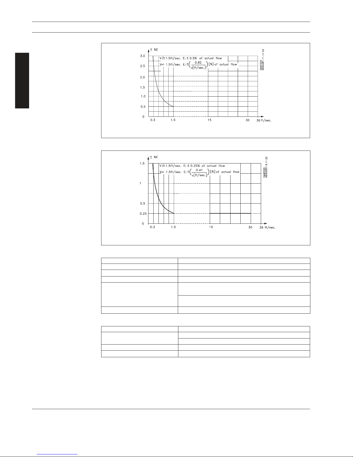
MAG 5000 or MAG 6000 used with MAG 3100 W or MAG 1100 PFA2.6
Meter uncertainty
V: Actual flow velocity [ft./s]
E: Meter uncertainty as a percentage of actual flow
MAG 6000 used with MAG 3100, MAG 1100 Ceramic or MAG 5100 W
V: Actual flow velocity [ft./s]
E: Meter uncertainty as a percentage of actual flow
Reference conditions (ISO 9104 and DIN/EN 29104)
Temperature of medium 68°F ±9 F
Ambient temperature 68°F ±9 F
Supply voltage Un ±1%
Warming-up time 30 min.
Incorporation in pipe section Inlet section 10 * Nominal pipe size (sizes up to 48"),
5 * Nominal pipe size (sizes up to 48")
Outlet section 5 * Nominal pipe size (sizes up to 48"),
3 * Nominal pipe size (sizes up to 48")
Flow conditions Fully developed flow profile
Additions in the event of deviations from reference conditions
Current output As pulse output ±(0.1% of actual flow +0.05% FSO)
Effect of ambient temperature Display/frequency/pulse output: < ±0.003% / < ±0.0017°F
Current output: < ±0.005% / < ±0.0028°F
Effect of supply voltage < 0.005% of measuring value on 1% change
Repeatability ±0.1% of actual flow for V ³ 1.5 ft./sec.
2. Specifications
Page 15
MAGFLO
â
15
Specif ications
2. Specifications
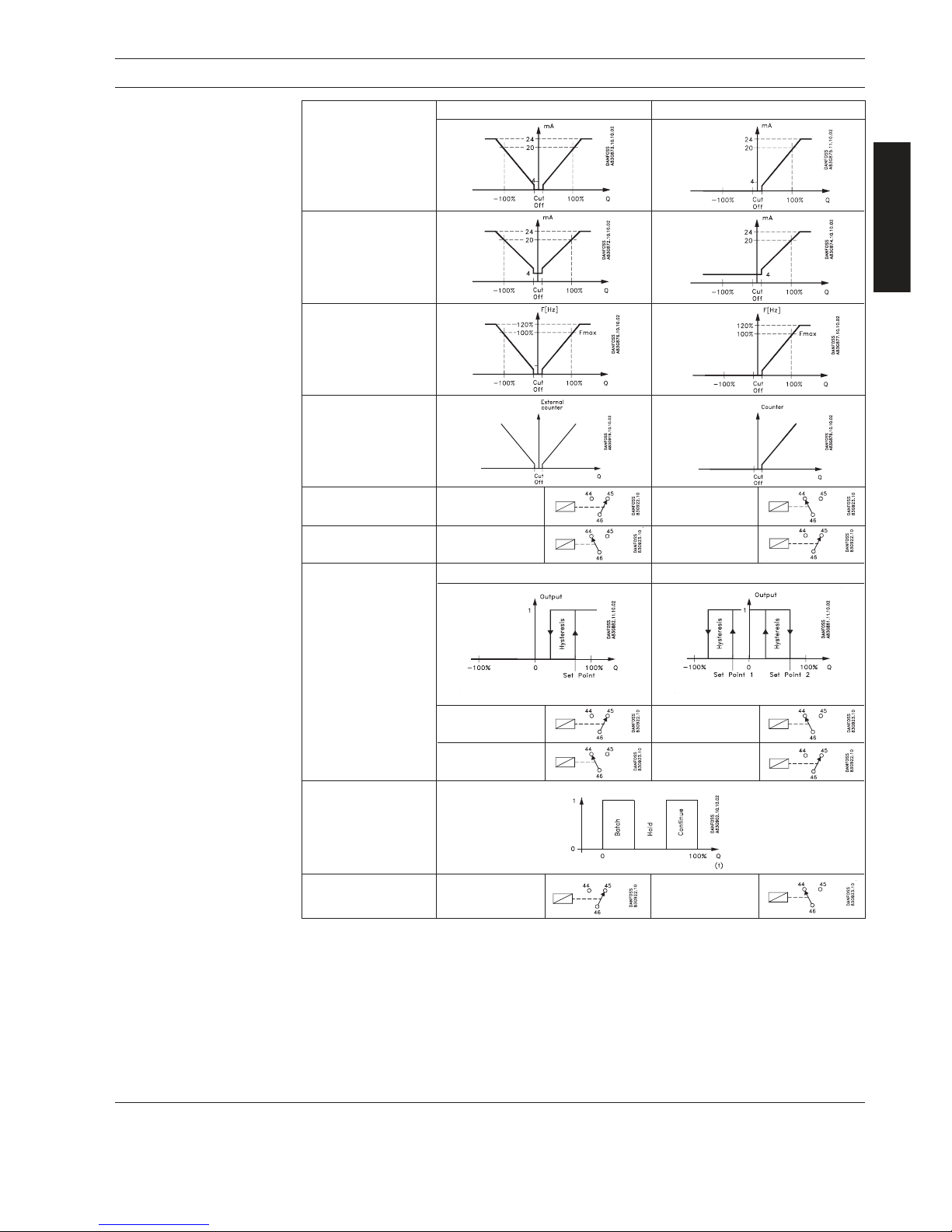
2.7
Output characteristics
MAG 5000 and MAG 6000
Output characteristics Bidirectional mode Unidirectional mode
0-20 mA
4-20 mA
Freque ncy
Pulse output
Relay
Power down Active
Error relay No error Error
Limit switch or 1 set point 2 set points
direction switch
Low flow Intermediate flow
(Reverse flow)
High flow High flow/
(Forward flow) Low flow
Batch on digital
ou t put
Batch on relay Hold Batch
Page 16
MAGFLO
â
Specif ications
16
Coil cable Electrode cable
Basic data No. of conductors 2 3
Min. sqr. area 0.5 mm2/20 gage 0.2 mm2/22 gage
Shield Yes Yes
Max. capacitance N.A. 107 pF/ft.
Max. cable loop Media temperature: < 210°F 40 W N.A.
resistance < 390°F 6 W N.A.
2. Specifications
2.8.1
Sensor cables and
conductivity of medium
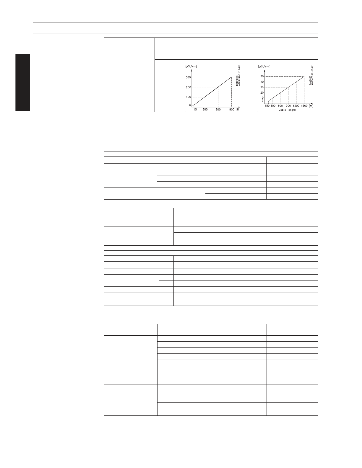
Note
· For detection of empty pipe the min. conductivity must always be ³ 20 mS/cm. and the max.
length of electrode cable when remote mounted is 150 ft. Special shielded cables must be used.
· For remote mounting in Ex applications special cable cannot be used, empty pipe cannot be
detected and the electrical conductivity must be ³ 30 mS/cm.
· For remote mounted CT installations the max. cable length is 600 ft.
2.8.2
Minimum accept data for
cable
2.9
Cable specification
(Supplied by Danfoss)
Standard cable Special cable
(electrode/coil) (electrode)
Basic data No. of conductors 3 3
Sqr. area 1.5 mm2/18 gage 0.25 mm2/22 gage
Shield Yes Double
Color code Brown, blue, black Brown, blue, black
Outside color Grey Grey
Ext. diameter 0.3" 0.32"
Conductor Flexible CU Flexible CU
Isolation material PVC PVC
Amb. temperature · Flexible installation -23 to 160°F -23 to 160°F
· Non flexible installation -20 to 160°F -20 to 160°F
Cable parameter Capatance 49.24 pF/ft. N.A.
Inductance 0.178 mH/ft. N.A.
L/R 43.83 mH/W N.A.
2.9
HART
â
communication
add-on module
Applic ation MAG 6000, MAG 6000 CT
Optional available as factory mounted in MAG 5000
Communication standard Bell 202 frequency shift keying (f.s.k.) standard
Communication modes · Single loop mode
· Multi-drop mode, 15 slave devices
Com municat or Rosemount Hand-held communicator, type 275
Cable specification
Communication mode
/ Single loop
Q [mm2] CU ³ 0.2 mm2/AWG 24
Shield Yes (Overall shield)
Loop resistance
Min.
230 W
Max.
800 W
Cable capacity £ 122 pF/ft.
Cable length 5000 ft.
Twisted pair Yes
HARTâ is a registered trademark of the HART Communication Foundation.
Conductivity of Integral mount installation:
medi um Liquids with an electrical conductivity ³ 5 mS/cm.
For a conductivity between 5 and 10 mS/cm, the repeatability may degrade to
±0.5% of actual flow.
Remote mount
installation:
Standard electrode cable Special electrode cable
Page 17
17
MAGFLO
â
3. Product selection guidelines
Product selection
guidelines
3. Product selection guidelines
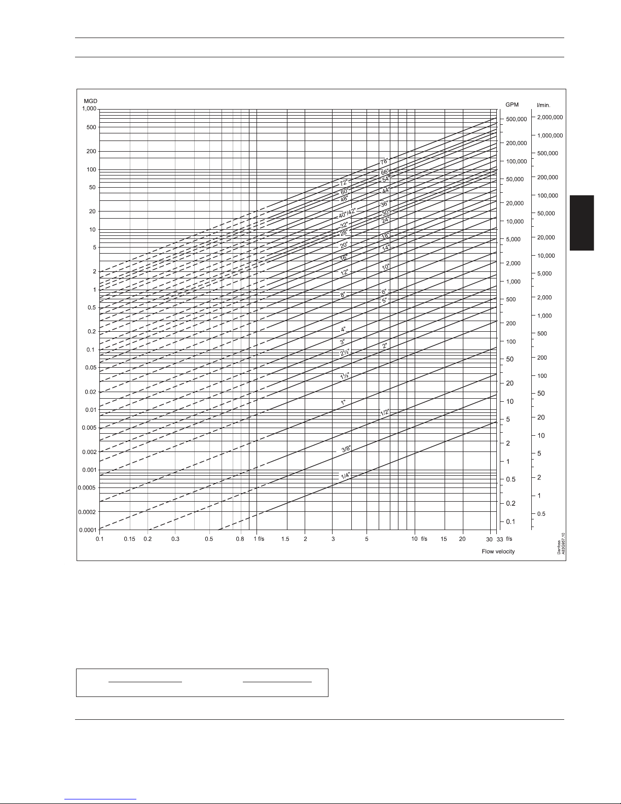
3.1 Sizing table (1/4" to 78")
The table shows the relationship between flow velocity V, flow quantity Q and sensor dimension size.
Guidelines for selection of sensor
Min. measuring range: 0-0.8 ft./sec. Max. measuring range: 0-33 ft./sec.
Normally the sensor is selected so that the nominal flow velocity is within the measuring range 1-15 ft./sec.
Flow velocity calculation formula:
GPM = (Pipe I.D. inches)2 x velocity (ft./sec.) x 2.448
V =
GPM x 0.408
(Pipe I.D. inches)
2
or V =
(Pipe I.D. inches)
2
MGD x 283.67
Page 18
18
MAGFLO
â
3. Product selection guidelines
Product selection
guidelines
3.2.1
Minimum conductivity
Applicati ons Min. conductivity
Integral mounted 5 m S/cm
Remote mounted 5 mS/cm
(Please see 2.7.1 for further details)
With empty pipe detection 20 mS/cm
(Please see 2.7.1 for further details)
Ex-installations
(Remote mounted only)
30 mS/cm
(Please see 2.7.1 for further details)
District heating systems
(Without DC cleaning unit)
250 mS/cm max. 150 ft.
3.2.2
Liner selection guide
Liner Applica tions
Ceramics Al2O
3
General purpose, agressive chemicals
PFA General purpose, dairy, food and beverage
Neoprene General purpose, sewage
EPDM Drinking water, sea water
PTFE Agressive chemicals, paper and pulp, high temperature applications
Linate x
â
Abrasive media and mining slurries
Ebo ni te Drinking water
3.2.3
Electrode selection guide
Electrodes Applications
AISI 316 Ti General purpose, water, sewage and district heating
AISI 316 Ti Ceramic coated High content of fibres, paper pulp
Hastelloy C-276 Good chemical proporties, sea water
Titanium Chlorine, chlorite, nitric and chromic acids
Textile bleaching industry
Tantalum Almost any acid solution
Platinum and platinum/irridium The ultimate electrode material. Unaffected by most liquids
3.3
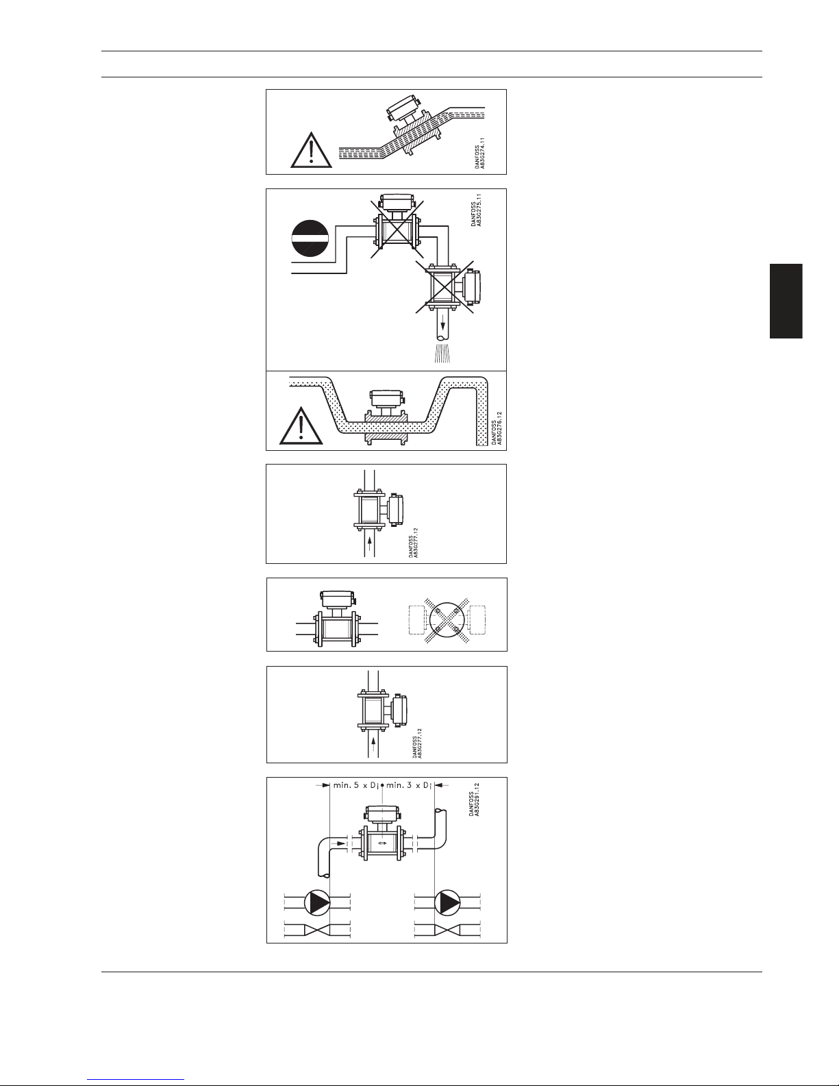
Installation conditions
Reading and operating the flowmeter is possible under almost any installation conditions
because the display can be oriented in relation to
the sensor.
Page 19
19
MAGFLO
â
3. Product selection guidelines
Product selection
guidelines
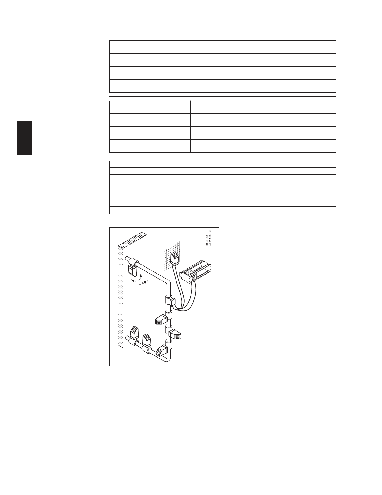
The sensor must be mounted as shown in the
left figure. Do not mount the sensor as shown in
the right figure. This will position the electrodes
at the top where there is possibility for air bubbles
and at the bottom where there is possibility for
mud, sludge, sand etc.
Recommended installation is in a vertical/inclined pipe to minimize the wear and deposits
in the sensor.
To achieve accurate flow measurement it is
essential to have straight lengths of inlet and
outlet pipes and a certain distance between
pumps and valves.
It is also important to center the flowmeter in
relation to pipe flanges and gaskets.
For accurate flow measurement, the sensor
must be installed in a section of straight pipe,
free of valves, elbows, tees, etc.
· Min. 5 x I.D. upstream
· Min. 3 x I.D. downstream
Installation in horizontal
pipes
Measuring abrasive
liquids and liquids
containing particles
Inlet and outlet conditions
Avoid:
· Installation at the highest point in the pipe
system
· Installation in vertical pipes with free outlet
For partially filled pipes or pipes with downward
flow and free outlet the flowmeter should be
located in a U-tube.
Recommended flow direction: upwards. This
minimizes the effect on the measurement of any
gas/air bubbles in the liquid.
Installation in vertical pipes
3.3
Installation conditions
(continued)
To ensure optimum flow measurement, attention should be paid to the following:
The sensor must always be completely full with
liquid.
Page 20
20
MAGFLO
â
3. Product selection guidelines
Product selection
guidelines
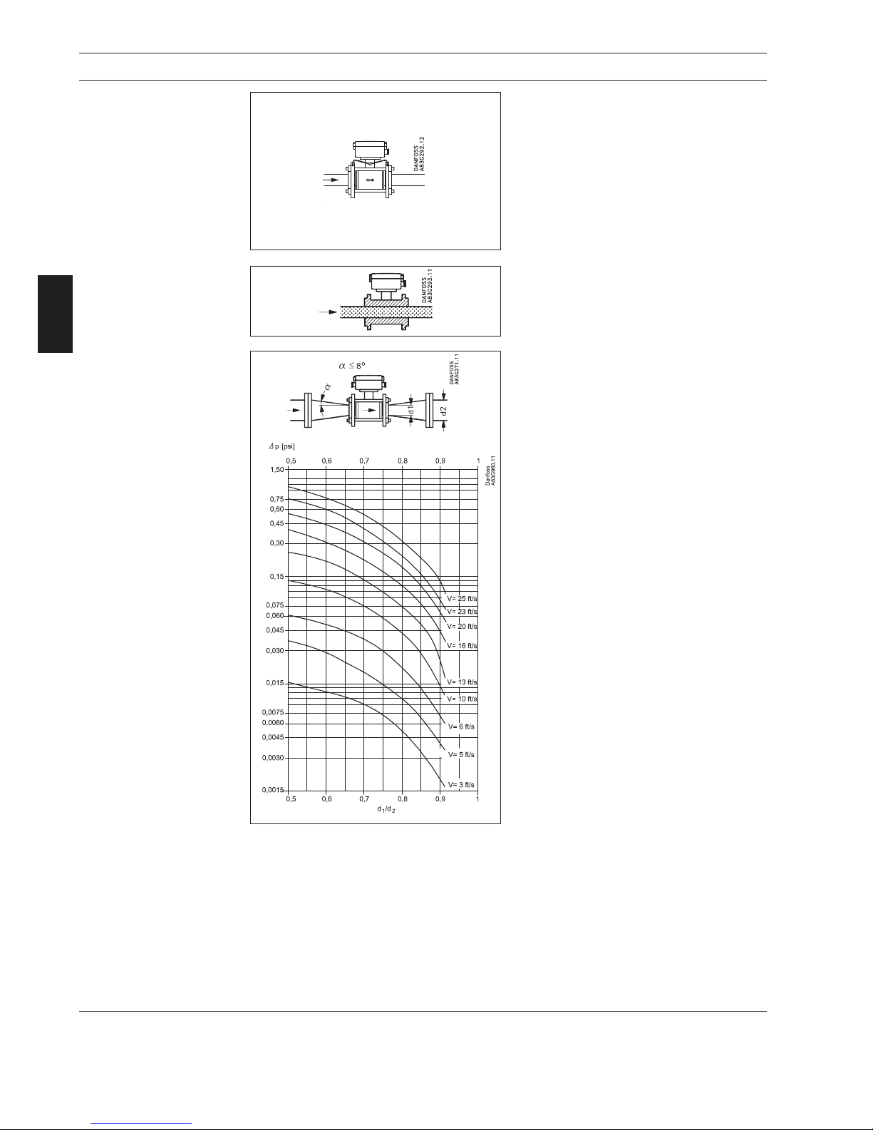
Avoid a vacuum in the measuring pipe, since
this can damage certain liners.
See "Specifications", section 2.
The flowmeter can be installed between two
reducers.
With an 8° reducer the following pressure drop
curve applies. The curves are applicable to
water.
Example:
A flow velocity of 10 ft./sec. (V) in a sensor with
a diameter reduction from 4" to 3" (d1/d2 = 0.8)
gives a pressure drop of 0.04 psi.
Vacuum
Installation in large pipes
The electrical potential of the liquid must always be equal to the electrical potential of the
sensor. This can be achieved in different ways
depending on the application:
A. Built-in grounding electrodes. (MAG 3100
and MAG 3100 W).
B. Direct metallic contact between sensor and
fittings. (MAG 1100 FOOD).
C. Wire jumper between sensor and adjacent
flanges. (MAG 1100 and MAG 3100).
D. Optional graphite gaskets on MAG 1100.
(Standard for MAG 1100 High temperature).
Potential equalization
(Grounding)
Page 21
21
MAGFLO
â
3. Product selection guidelines
Product selection
guidelines
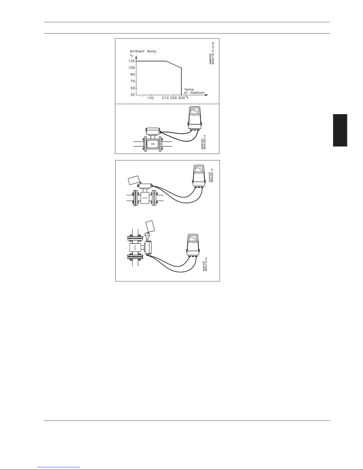
The sensor and signal converter can be installed either integral mount or remote.
With integral mount installation the temperature of medium must be according to the graph.
With remote installation, the cable length and
type described under "Specifications", section
2 must be used.
Integral mount/remote
installation
Suggestions for the direct
burial of MAG 3100 &
MAG 5100 W sensors
If MAGFLO 3100 or MAG 5100 W sensors are buried directly into the ground, we suggest the
following precautions:
The SENSORPROMâ unit should be removed from the terminal box on the sensor and relocated
in the signal converter remote mounting prior to burying the sensor.
All the sensor data plate information and serial number should be recorded for each sensor prior
to burying. This will ensure correct matching with the SENSORPROM
â
unit.
The sensor should be potted with the optional IP68 submersion kit and suitable coil and
electrode cables should be used prior to burying.
The use of pea gravel, at least 12 inches all around the sensor, is recommended. This provides
some drainage and prevents dirt from caking onto the sensor. It also helps locate the sensor
should excavation be necessary.
Before covering the pea gravel with earth, we suggest the use of electrical cable identification
tape laid above the gravel.
The sensor should not be subject to heavy vehicles applying excessive weight above the sensor
or pipeline.
NEMA 6 submersible kit
(option)
If the sensor is going to be buried or permanently submerged, the terminal box must
be encapsulated with silicon dielectric gel.
The optional kit has two components.
Mix the two components well (without inducing
air) and pour the contents into the terminal box.
The material is a non-toxic, transparent, selfhealing gel which cures in approx. 24 hours.
The gel can be penetrated with test instruments or be removed in case of cable replacement.
Horizontal installation
Vertical installation
Page 22
22
MAGFLO
â
3. Product selection guidelines
Product selection
guidelines
The Danfoss cleaning unit can be used with MAG 5000 or 6000 in rack mount versions.
The cleaning unit can be used in applications where the liner material and subsequently the
electrodes may be coated with deposits. If the coating is electrically insulating, the electrode signal
will be reduced. If the coating is electrically conductive, the electrode signal will be partly shortcircuited. In both cases the accuracy of the meter will decrease (dependent on the type and thickness
of the coating).
Note
The cleaning unit cannot be used for flammable or explosive media!
Empty pipe detection and cleaning facility cannot be used at the same time.
The cleaning unit cleans the electrodes electro-chemically by applying a voltage to the electrodes
for approx. 60 sec. While cleaning, the signal converter stores and holds the latest measured flow
reading on the display and also the signal outputs. After an additional pausing period of 60 sec. the
flowmeter resumes normal measurement and the cleaning is now completed.
The relay in the signal converter activates the cleaning cycle. In the relay output menu (under
cleaning) the cleaning interval can be set between 1 hour and 24 hours.
Cleaning should only take place with liquid in the pipe. This can be achieved via the empty pipe
detection. It is therefore recommended to select “empty pipe detection” ON when using the cleaning
unit.
The cleaning sequence can also be controlled manually through the electrical input of the signal
converter. Before this is done, ensure that the measuring pipe is full.
Theory of operation
3.4
Cleaning unit
AC-cleaning
(For non-conductive coatings)
DC-cleaning
(For conductive coatings)
AC-cleaning is used to remove fatty deposits on the electrodes. Fatty deposits are seen from
Slaughter houses and in rare instances from wastewater applications and water applications with
oil residuals. During the cleaning process, the surface of the electrodes get warmer, which tends
to soften grease particles and the gas bubbles generated mechanically lift deposits away from the
surface of the electrodes.
DC-cleaning is used to eliminate electrically conductive deposits in the measuring pipe influencing
the measuring accuracy.
Particularly in district heating applications, an electrically conductive deposit (magnetite) may occur
and short-circuit the electrode signal. In this case the accuracy of the meter decreases and the signal/
noise conditions of the meter become inferior. The problem only arises if the conductivity of the water
is less than approx. 250 mS/cm.
During DC-cleaning, electrolysis takes place where the flow of electrons removes the particle
deposits from the electrode area.
Page 23

23
MAGFLO
â
3. Product selection guidelines
Product selection
guidelines
A signal converter can be supplied in a version
tested and approved for custody transfer (CT).
The internal counter can accordingly be used
for billing.
This requires verification, sealing and setting of
the signal converter together with the sensor for
a specific flow range. After sealing, the data on
the signal converter must not be changed.
3.5
Custody transfer
approval
The sealing of the signal converter is done by
placing sealing marks on the signal converter
and on the connection plate in the terminal box.
3.6
Signal converter
MAG 5000 CT, 6000 CT
Sealing
The final (lead) sealing is carried out as shown:
MAG 6000 CT is installed like a standard MAG 6000 except for the final sealing.
Calibration sealing has been carried out at calibration.
Page 24

24
MAGFLO
â
3. Product selection guidelines
Product selection
guidelines
MAG 6000 rack mount with integral safety barrier (ia/ib) for remote mounting in safe area
Approval [EEx ia/ib] llB. The safety barrier is to be used with sensors MAG 1100 Ex and MAG 3100
Ex, 1/4" to 4". When this safety barrier is used, the coil circuit is intrinsic safety “ib” and the electrode
circuit is intrinsic safety “ia”.
Sensors
The sensors can be one of the following type.
MAG 1100 Ex for mounting in Ex areas
1/4'' to 4'' approval EEx [ia/ib] llB T4..T6. DEMKO no. 97D.121909X. DN 6 - 100.
MAG 3100 Ex for mounting in Ex areas
The sensor carries the approval:
1
/2" to 1" EEx [ia/ib] llB T4..T6, DEMKO no. 98E.123914X
11/2" to 12" EEx [ia/ib] llB T4..T6, DEMKO no. 98E.123915X
The electrode circuit in the sensors is manufactured to an intrinsically safe category “ia” and the coil
circuit to an intrinsically safe category “ib”, achieved by an integrated and patented protection circuit.
Marking
The marking has the following meaning according to European Norm EN 50014.
E: Certified to CENELEC standard.
Ex: Designates explosion proof material and indicates that the apparatus has been
approved in accordance with a certificate issued.
i: “Intrinsic safety” is a protection ensuring that the energy in the electric circuit is too small to
ignite the explosive atmosphere. There are two categories of intrinsic safety: “ia” and “ib”.
ia: In intrinsic safety category “ia”, the circuit must remain safe, even in the event of two
simultaneous errors occurring that are independent of one another.
ib: In intrinsic safety category “ib” the circuit must remain safe if an error occurs.
ll: Designates that the apparatus may be used in all areas (Except mining).
B: Indicates the gas group in which the unit may be used.
T4..T6 The temperature class describes the maximum temperature which any exposed surface
of the equipment may reach. The sensor can have temperature class T3, T4, T5 or T6
depending on the temperature of the media. Please see technical data for the sensor.
T3: Max. surface temperature 390 °F => (Max. media temperature 355 °F)
T4: Max. surface temperature 275 °F => (Max. media temperature 250 °F)
T5: Max. surface temperature 210 °F => (Max. media temperature 195°F)
T6: Max. surface temperature 185 °F => (Max. media temperature 165 °F)
3.7
Ex installations
Page 25
25
MAGFLO
â
D & W
MAG 1100, integral/remote mount/separate4. Dimensions and weight
4.1
Sensor MAG 1100
4. Dimensions and weight
1
) 0.5" shorter when the AISI terminal box is used. (Ex and high temperature 390°F).
2
) With signal converter MAG 5000 or MAG 6000 installed, weight is increased by approx. 1.8 lbs.
The total built-in length "L" [inch] before assembling depends on the gasket selected.
Size EPDM Graphite PTFE(Teflo n) Without gasket Grounding ring
1
/4" 2.52 2.60 2.75 2.52 3.03
3
/8" 2.52 2.60 2.75 2.52 3.03
1
/2" 2.56 2.60 2.75 2.52 3.03
1" 3.15 3.19 3.35 3.10 3.62
11/2" 3.74 3.78 3.94 3.70 4.21
2" 4.13 4.17 4.33 4.05 4.61
21/2" 5.12 5.15 5.31 5.05 5.60
3" 6.10 6.14 6.30 6.00 6.57
4" 7.28 7.31 7.48 7.20 7.76
The MAG 1100 1/4" and 3/8" are prepared for assembly with the 1/2" pipe connection.
The built-in length "L" varies dependent on the gasket choice:
Without gasket EPDM Graphite Teflo n
L [inch] 5.9 5.9 6.0 6.1
Size A1) B1) A
1
B
1
D D
i
D
i
D
p
DGWeig ht2)
(Al2O3) (PFA )
[inc h] [i nch] [in ch] [ inc h] [inch ] [ in ch] [ inc h] [in ch ] [ inc h] [lbs]
1
/4" 6.14 7.13 12.16 13.15 1.90 0.24 0.68 1.34 10.6
3
/8" 6.14 7.13 12.16 13.15 1.90 0.39 0.39 0.53 1.34 10.6
1
/2" 6.14 7.13 12.16 13.15 1.90 0.59 0.63 0.68 1.57 10.6
1" 6.46 7.72 12.48 13.74 2.50 0.98 1.02 1.12 2.20 10.8
11/2" 6.93 8.58 12.95 14.61 3.31 1.57 1.50 1.71 2.95 16.5
2" 7.24 9.25 13.27 15.27 4.00 1.97 1.97 2.15 3.54 20.3
21/2" 7.64 10.00 13.66 16.02 4.72 2.56 2.60 2.68 4.41 26.5
3" 7.87 10.47 13.90 16.50 5.24 3.15 3.19 3.25 4.88 33.1
4" 8.39 11.50 14.41 17.52 6.26 3.94 3.94 4.22 5.91 48.5
Signal converter removal clearance
Page 26
26
MAGFLO
â
D & W
4.2
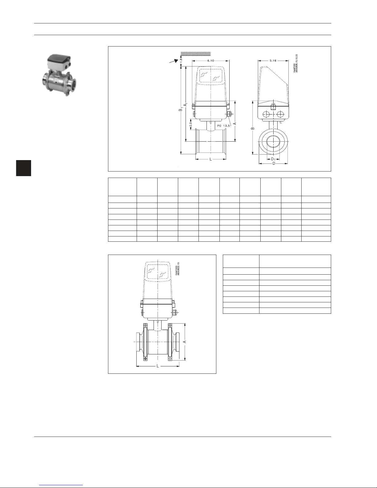
Sensor MAG 1100 FOOD
MAG 1100 FOOD, integral or remote mount and separate
4. Dimensions and weight
Size L A A
1
B B
1
D D
i
D
i
Weight 1)
(Al2O3) (PFA)
[inch] [inch] [inch] [inch] [inch] [inch] [inc h] [inch] [lbs]
3
/8" 2.52 6.14 12.16 7.40 13.43 2.52 0.39 0.39 4.8
1
/2" 2.52 6.14 12.16 7.40 13.43 2.52 0.59 0.63 4.8
1" 3.11 6.46 12.48 7.98 14.01 3.05 0.98 1.02 4.9
11/2" 3.70 6.93 12.95 8.72 14.74 3.58 1.57 1.50 7.5
2" 4.09 7.24 13.27 9.59 15.61 4.68 1.97 1.97 9.2
21/2" 5.16 7.64 13.66 10.20 16.22 5.12 2.56 2.60 12.0
3" 6.14 7.87 13.90 10.93 16.95 6.10 3.15 3.19 15.0
4" 7.32 8.39 14.41 11.99 18.01 7.20 3.94 3.94 22.0
1
) With signal converter MAG 5000 or MAG 6000 installed, weight is increased by approx. 1.8 lbs.
Built-in length
Size A
[inc h]
3
/8" 3.90
1
/2" 3.90
1" 4.45
11/2" 4.96
2" 6.06
21/2" 6.50
3" 7.87
4" 8.86
Signal converter removal clearance
Page 27

27
MAGFLO
â
D & W
Accessories
MAG 1100 FOOD
4. Dimensions and weight
Tri-Clover
â
and Tri-Clampâ are registered trademarks for Ladish Co.
Weld-in type
Tri-Clover
®
Di Do
[inc h] [in ch] [inch] [i nch ] [inc h]
3
/
8
3
/81 1/20.37
1
/
2
1
/
2
1
/21 1/20.62
3
/
4
1 1 1 1/20.87 1
1 1/21 1/21 1/21.37 1 1/
2
2 2 1 1/21.87 2
2 1/22 1/21 3/42.37 2 1/
2
3 3 2 2.87 3
4 4 2 3.83 4
Adapter
size
Sensor
size
Clamp type
Tri -Clamp
®
Di Do
[inc h] [inc h] [inch] [i nc h] [inch]
3
/
8
3
/81 1/20.37 0.98
1
/
2
1
/21 1/20.62 0.98
1 1 1 1/20.87 1.99
1 1/21 1/21 1/21.37 1.99
2 2 1 1/21.87 2.52
2 1/22 1/21 3/42.37 3.05
3 3 2 2.87 3.58
4 4 2 3.83 4.70
Adapter
size
Sensor
size
L
L
Page 28

28
MAGFLO
â
D & W
mm inch mm inch mm inch mm inch mm inch mm inch mm inch
25 1" 187 7.4 N/A N/A N/A N/A 200 7.9 200 7.9 N/A N/A
40 1½” 197 7.8 N/A N/A N/A N/A 200 7.9 200 7.9 N/A N/A
50 2" 188 7.4 N/A N/A 200 7.9 N/A N/A 200 7.9 N/A N/A
65 2½” 194 7.6 N/A N/A 200 7.9 N/A N/A 200 7.9 N/A N/A
80 3" 200 7.9 N/A N/A 200 7.9 N/A N/A 200 7.9 N/A N/A
100 4" 207 8.1 N/A N/A 250 9.8 N/A N/A 250 9.8 N/A N/A
125 5" 217 8.5 N/A N/A 250 9.8 N/A N/A 250 9.8 N/A N/A
150 6" 232 9.1 N/A N/A 300 11.8 N/A N/A 300 11.8 N/A N/A
200 8" 257 10.1 350 13.8 350 13.8 N/A N/A 350 13.8 N/A N/A
250 10" 284 11.2 450 17.7 450 17.7 N/A N/A 450 17.7 N/A N/A
300 12" 310 12.2 500 19.7 500 19.7 N/A N/A 500 19.7 N/A N/A
350 14" 362 14.3 550 21.7 550 21.7 N/A N/A 550 21.7 N/A N/A
400 16" 387 15.2 600 23.6 600 23.6 N/A N/A 600 23.6 N/A N/A
450 18" 418 16.5 600 23.6 600 23.6 N/A N/A 600 23.6 N/A N/A
500 20" 443 17.4 625 24.6 625 24.6 N/A N/A 680 26.8 N/A N/A
600 24" 494 19.4 750 29.5 750 29.5 N/A N/A 820 32.3 N/A N/A
700 28" 544 21.4 875 34.4 875 34.4 N/A N/A N/A N/A 875 34.4
750 30" 571 22.5 N/A N/A N/A N/A N/A N/A N/A N/A 937 36.9
800 32" 606 23.9 1000 39.4 1000 39.4 N/A N/A N/A N/A 1000 39.4
900 36" 653 25.7 1125 44.3 1125 44.3 N/A N/A N/A N/A 1125 44.3
1000 40" 704 27.7 1250 49.2 1250 49.2 N/A N/A N/A N/A 1250 49.2
42" 704 27.7 N/A N/A N/A N/A N/A N/A N/A N/A 1250 49.2
1100 44" 755 29.7 N/A N/A N/A N/A N/A N/A N/A N/A 1375 54.1
1200 48" 810 31.9 1500 59.1 1500 59.1 N/A N/A N/A N/A 1500 59.1
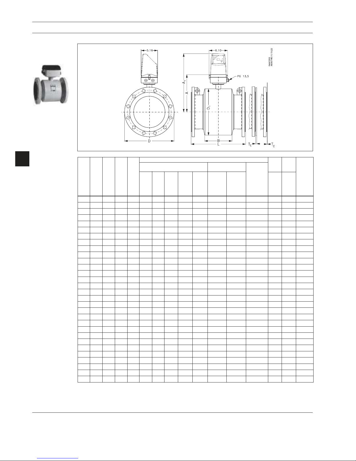
4.3
Sensor MAG 5100 W
Dimensions
AWWA
Nominal
size
A
L
PN 10
PN 16 PN 40 Class 150
4. Dimensions and weight
Page 29

29
MAGFLO
â
D & W
4. Dimensions and weight
mm inch kgs lbs kg s lbs k gs lbs k g s lbs kgs lbs
25 1" N/A N/A N/A N/A 4 9 4 9 N/A N/A
40 1½” N/A N/A N/A N/A 7 15 6 13 N/A N/A
50 2" N/A N/A 9 20 N/A N/A 8 20 N/A N/A
65 2½” N/A N/A 10.7 24 N/A N/A 11 24 N/A N/A
80 3" N/A N/A 11.6 26 N/A N/A 13 28 N/A N/A
100 4" N/A N/A 15.2 33 N/A N/A 19 41 N/A N/A
125 5" N/A N/A 20.4 45 N/A N/A 24 52 N/A N/A
150 6" N/A N/A 26 57 N/A N/A 29 64 N/A N/A
200 8" 48 106 48 106 N/A N/A 56 124 N/A N/A
250 10" 64 141 69 152 N/A N/A 79 174 N/A N/A
300 12" 76 167 86 189 N/A N/A 110 243 N/A N/A
350 14" 100 220 116 255 N/A N/A 131 289 N/A N/A
400 16" 127 280 144 317 N/A N/A 165 364 N/A N/A
450 18" 152 335 178 393 N/A N/A 176 388 N/A N/A
500 20" 184 405 232 512 N/A N/A 235 518 N/A N/A
600 24" 258 568 343 736 N/A N/A 345 761 N/A N/A
700 28" 315 693 350 772 N/A N/A N/A N/A 309 681
750 30" N/A N/A N/A N/A N/A N/A N/A N/A 480 1058
800 32" 410 904 442 975 N/A N/A N/A N/A 421 928
900 36" 512 1129 550 1213 N/A N/A N/A N/A 539 1188
1000 40" 650 1433 732 1614 N/A N/A N/A N/A 670 1477
42" N/A N/A N/A N/A N/A N/A N/A N/A 700 1544
1100 44" N/A N/A N/A N/A N/A N/A N/A N/A 1100 2426
1200 48" 990 2183 1106 2439 N/A N/A N/A N/A 1030 2271
AWWA
Nominal size
PN 10
PN 16 PN 40 Class 150
MAG 5100 W weight
The effect of temperature on
working pressure
MAG 5100 W
Metric (Pressure in bar)
Sizes 25 mm, 40 mm & > 600 mm
Flange spec. Flange Temperature °C
rating -5 10 50 90
EN 1092-1 PN 10 10.0 10.0 9.7 9.4
PN 16 16.0 16.0 15.5 15.1
PN 40 40.0 40.0 38.7 37.7
ANSI B16.45 150 lb 19.7 19.7 19.3 18.0
AWWA C-207 Class D 10.3 10.3 10.3 10.3
Sizes 50 mm to 600 mm
EN 1092-1 PN 10 10.0 10.0 10.0 8.2
PN 16 10.0 16.0 16.0 13.2
PN 40 10.0 40.0 40.0 32.9
ANSI B16.45 150 lb 10.0 19.7 19.7 16.2
Imperial (Pressure in Psi)
Sizes 1", 1½”, & > 24"
Flange spec. Flange Temperature °F
rating 25 50 125 200
EN 1092-1 PN 10 145 145 141 136
PN 16 232 232 225 219
PN 40 580 580 561 547
ANSI B16.45 150 lb 286 286 280 261
AWWA C-207 Class D 150 150 150 150
Sizes 2" to 24"
EN 1092-1 PN 10 145 145 145 119
PN 16 145 232 232 191
PN 40 145 580 580 477
ANSI B16.45 150 lb 145 286 286 235
Page 30
30
MAGFLO
â
D & W
4. Dimensions and weight
4.4
Sensor
MAG 3100 and
MAG 3100 W
MAG 3100 & MAG 3100 W, integral or remote mount and separate
Size A1) A
1
B D
1
L
2)
EN 1092-1-2001 ANSI 16.5 AWWA
T
C
3)
T
E
3)
Weight
4)
C-207
PN PN PN PN PN Class Class
Class
6, 25 40 2.52 100 150 300
D
10,
16
[inch] [inch] [inch] [inch] [inch] [inch] [inch] [inch] [inch] [inch] [inch] [inch] [inch] [inch] [inch] [lbs]
1
/2" 7.36 13.31 2.32 4.09 7.87 7.87 7.87 - - 7.87 7.87 - 0.24 11
1" 7.36 13.31 2.32 4.09 7.87 7.87 7.87 - 10.24 7.87 7.87 0.05 0.24 13
11/2" 7.76 13.70 3.23 4.88 7.87 7.87 7.87 - 11.02 7.87 7.87 0.05 0.24 17
2" 8.07 14.01 2.83 5.47 7.87 7.87 7.87 10.87 11.81 7.87 7.87 0.05 0.24 28
21/2" 8.35 14.29 2.83 6.06 7.87 7.87 7.87 12.60 13.78 7.87 10.71 0.05 0.24 30
3" 8.74 14.69 2.83 6.85 7.87 10.71 10.71 12.72 13.39 10.71 10.71 0.05 0.24 33
4" 9.53 15.47 3.35 8.43 9.84 9.84 9.84 14.96 15.75 9.84 12.20 0.05 0.24 44
5" 10.04 15.98 3.35 9.41 9.84 9.84 9.84 16.54 17.72 9.84 13.10 0.05 0.24 55
6" 10.87 16.81 5.39 11.10 11.81 11.81 11.81 16.34 17.72 11.81 11.81 0.05 0.24 66
8" 11.97 17.91 5.39 13.31 13.78 13.78 13.78 18.90 20.87 13.78 13.78 0.05 0.31 110
10" 13.07 19.02 5.39 15.47 17.72 17.72 17.72 21.65 24.41 17.72 17.72 0.05 0.31 155
12" 14.05 20.00 5.39 17.48 19.69 19.69 19.69 23.62 26.77 19.69 19.69 0.06 0.31 176
14" 14.25 20.20 10.63 17.76 21.65 21.65 21.65 27.56 31.50 21.65 21.65 - 0.06 0.31 242
16" 15.24 21.18 10.63 19.76 23.62 23.62 23.62 29.53 - 23.62 23.62 - 0.06 0.39 275
18" 16.45 22.40 12.20 22.16 23.62 23.62 23.62 - - 23.62 25.20 - 0.06 0.39 385
20" 17.44 23.39 13.78 24.17 24.61 24.61 26.77 - - 26.77 28.70 - 0.06 0.39 440
24" 19.45 25.39 16.93 28.15 29.53 29.53 29.53 - - 32.28 33.80 - 0.06 0.39 660
28" 21.42 27.36 19.69 32.13 34.45 - - - - - - 34.5 0.08 - 770
30" 22.48 28.43 21.89 34.21 - - - - - - - 36.9 0.08 - 880
32" 23.86 29.80 22.05 36.50 39.37 - - - - - - 39.4 0.08 - 1045
36" 25.71 31.65 24.80 40.63 44.29 - - - - - - 44.3 0.08 - 1233
40" 27.72 35.67 26.38 44.72 49.21 - - - - - - 49.2 0.08 - 1541
42" 27.72 35.67 26.38 44.72 49.21 - - - - - - 49.2 0.08 - 1541
44" 29.72 35.67 30.31 48.74 - - - - - - - 59.1 0.08 -
48" 31.89 37.83 31.18 53.07 59.06 - - - - - - 59.1 0.08 - 2751
54" 36.42 42.36 39.37 65.94 68.90 - - - - - - 68.9 0.12 - 3211
60" 38.27 44.21 40.15 65.83 - - - - - - - 73.8 0.12 - 3731
66" 40.35 46.30 44.49 75.39 78.74 - - - - - - 78.7 0.12 - 4257
72" 44.21 50.16 49.21 77.72 88.58 - - - - - - 88.5 0.12 - 5291
78" 48.15 54.09 54.13 85.59 98.43 - - - - - - 98.4 0.12 - 7492
1
)1/2" shorter with AISI terminal box (Ex and is PTFE high temperature with ss terminal box)
2
) When grounding rings are used, the thickness of the grounding ring must be added to the built-in length
3
) TC = Type C grounding ring, TE = Type E grounding ring
4
) Weights are for ANSI 150 without signal converter
D = Outside diameter of flange, see flange tables
Page 31

31
MAGFLO
â
D & W
4. Dimensions and weight
Grounding/protection ring
Size
t
1
t
2
Weight
[inch] [inch] [lbs]
1" to 10" 0.05 0.6 <1
12" to 24" 0.06 0.8 1-6
28" to 48" 0.08 1.0 6-11
54" to 78" 0.12 1.6 20-35
Size
t
1
Weight
[inch] [lbs]
1
/2" 0.2 0.15
1" to 6" 0.2 1-3
8" to 14" 0.3 4-9
16 to 24" 0.4 14-28
Type C flanges for liners of neoprene, EPDM, Linatexâ and ebonite.
Type E flanges for liners of PTFE.
Note
MAG 3100 high temperature (PTFE) is always equipped with 2 pcs. type E grounding flanges.
4.5
Signal converter
Integral mount signal converter
Weight: MAG 6000 and MAG 5000: 2.0 lbs
Weight: Wall bracket: 2.0 lbs
Wall mount signal converter
Rack mount, standard unit
Weight incl. back print:
MAG 5000: 1.8 lbs
MAG 6000: 1.8 lbs
Safety barrier (ia/ib): 2.2 lbs
Safety barrier (ia): 1.8 lbs
Cleaning unit: 2.0 lbs
Integral or wall mount
polyamide
Page 32
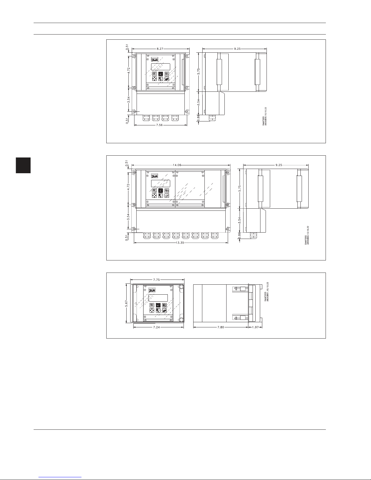
32
MAGFLO
â
D & W
4. Dimensions and weight
Wall mounting converter
Weight excl. signal converter: 8.0 lbs
Wall mounting converter
with cleaning unit or
intrincically safe barrier
Weight excl. signal converter: 7.0 lbs
Front panel mounting kit
Weight excl. signal converter: 3.0 lbs
Page 33
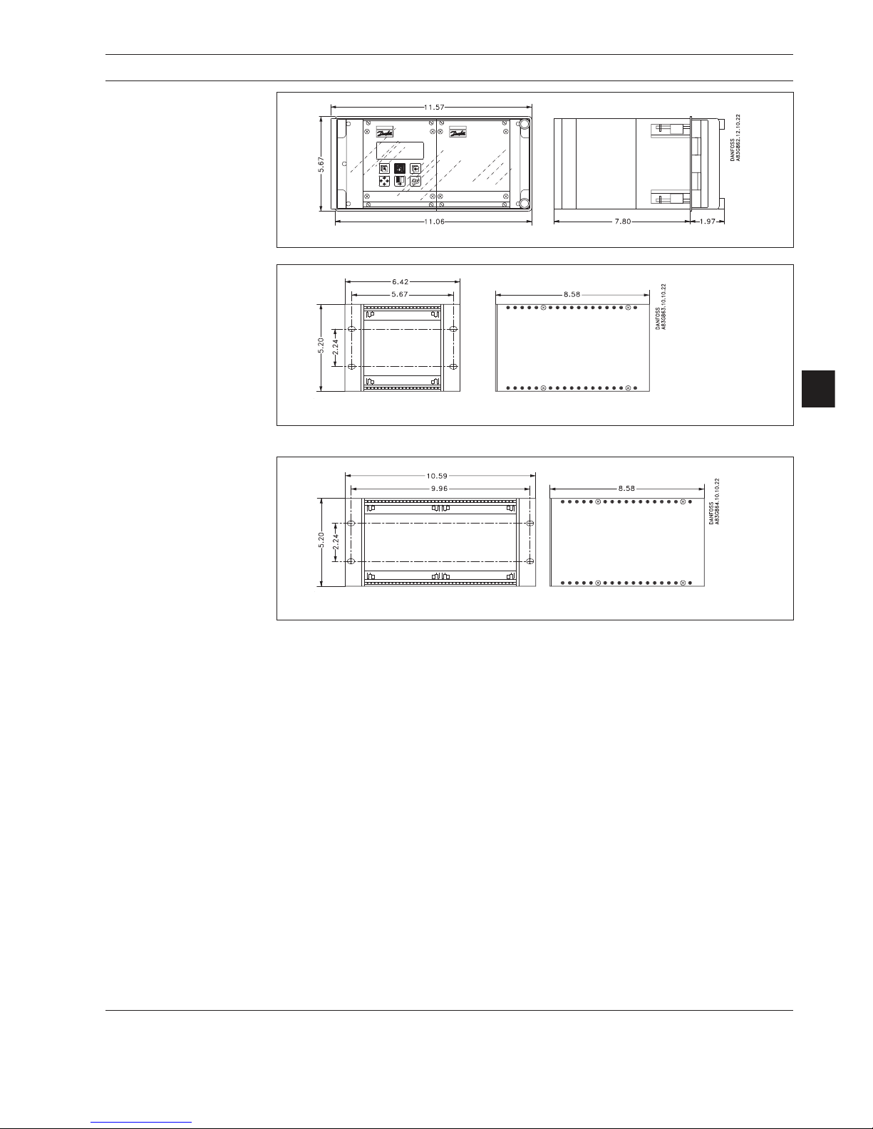
33
MAGFLO
â
D & W
Back of panel mounting kit
Back of panel mounting kit
for converter with intrinsically safe barrier or
cleaning unit
Weight: 2.0 lbs
Weight: 2.0 lbs
4. Dimensions and weight
Front panel mounting kit
for converter with intrinsically safe barrier or
cleaning unit
Weight excl. signal converter: 3.5 lbs
Page 34

34
MAGFLO
â
Sensor
To obtain optimum results from the measuring system, the chassis body of the sensor must have
the same electrical potential as the liquid being measured.
5. Installation of sensor
5.1
Potential equalization
(Grounding)
MAG 1100
Graphite gaskets EPDM or PTFE gaskets
Electrically
conductive
piping
A: Potential equalization with electri-
cally conductive graphite gaskets
B: Potential equalization using earth
strap supplied.
C: Potential equalization with electri-
cally conductive graphite gaskets
D: Potential equalization using sepa-
rate potential equalization ring
Electrically
non -conductive piping
MAG 1100 FOOD
The sensor must be installed between two
adapters. Potential equalization with the liquid
occurs automatically via these adapters and
through the adjacent pipe.
5. Installation of sensor
MAG 3100 W / MAG 3100
(except PTFE liner)
Potential equalization is carried out with the
built-in grounding electrodes. No further action
need to be taken.
Page 35

35
MAGFLO
â
Sensor
5. Installation of sensor
MAG 3100
PTFE liner
Electrically conductive piping
Use a grounding straps on one side.
Potential equalization, electrically conductive
pipe
Non-conductive piping
Use an grounding ringe. Place the ring between
flowmeter and the adjacent pipe flange.
Selection of grounding ring depends on medium, liner material and application.
Special attention must be given to systems with
cathodic protection.
Integral installation:
The signal converter must be supplied through
an isolation transformer. The terminal "PE" must
never be connected.
Remote installation:
The shield must only be connected at the sensor end via a 1.5 mF capacitor. The shield must
never be connected at both ends.
Isolated sensor:
If above mentioned connections are unacceptable, the sensor must be isolated from the pipe
work.
Liner Suitable
material grounding ring
PTFE Type E
Type of grounding flange depending on liner
material
With abrasive liquids, flowmeter inlet protection may be necessary. Here type C and E
grounding rings are used.
Type C (for all liners except PTFE) is inserted
between the flanges.
Type E (for PTFE liner only) is fitted to the flange.
When using a grounding ring, gaskets must
always be used between the adjacent pipe
flange and the grounding flange.
5.2
Inlet protection MAG 3100
5.3
Cathodic protected piping
Page 36

36
MAGFLO
â
Installation of signal
conv.
6. Installation of signal converter
6. Installation of signal
converter
6.1
Integral installation
MAG 5000 and MAG 6000
Step 1
Remove and discard the terminal box lid of the
sensor.
Fit the PG 13.5 cable glands for the supply and
output cables.
Step 2
Remove the two black plug assemblies for coil
and electrode cables in the terminal box and
connect them to their corresponding terminal
numbers on the connection board.
Step 3
Connect an earth wire between PE on connection board and bottom of connection box.
Connect the 2 pin connector and 3 pin connector
as shown.
Note
In earlier version the 3 pin connector was a 5 pin
connector.
Step 4
Mount the connection plate in the terminal box.
The SENSORPROM
®
unit connections will be
established automatically when the connection
plate is mounted in the terminal box.
Note
Check that your connection board lines up with
the SENSORPROM
®
unit, if not, move the
SENSORPROM
®
unit to the other side of the
terminal box.
Step 5
Fit the supply and output cables respectively
and tighten the cable glands to obtain optimum
sealing.
Please refer to the wiring diagram in section 7
for the electrical connections.
Mount the signal converter on the terminal box.
Not e
System will not register
flow if black plugs are not
connected to connection
board
Page 37

37
MAGFLO
â
Installation of signal
conv.
6. Installation of signal converter
1
2
4
3
5
Step 1
Use a screw driver to remove the outer frame.
Step 2
Loosen the 4 screws retaining the control
pad.
Step 3
Withdraw the control pad and turn it to the
required orientation.
Step 4
Tighten the 4 screws until a mechanical stop
is felt in order to obtain NEMA enclosure
rating.
Step 5
Snap-lock the outer frame onto the control
pad (click).
The signal converter can be mounted in either
direction as the arrow indicates without
turning the terminal box.
The terminal box can be rotated ±90° in order
to optimize the viewing angle of the signal
converter display/keypad:
Unscrew the four screws in the bottom of the
terminal box. Turn the terminal box to the required position and re tighten the screws
firmly.
Turning the control pad
Turning the signal
converter
Page 38

38
MAGFLO
â
Installation of signal
conv.
Locate the add-on module in the bottom of the
MAG 6000 signal converter.
6. Installation of signal converter
6.2.1
Add-on modules
(MAG 6000 only)
Press the add-on module forwards as far as
possible.
The add-on module has now been installed
and the signal converter is ready t o be
installed on the terminal box.
Communication to the operator menu and
electrically inputs and outputs is automatically established by power on.
Step 2 (All signal converter types)
Fit and connect the electrode and coil cables
as shown in section 7 “Electrical connections”.
The unshielded cable ends must be kept as
short as possible.
The electrode cable and the coil cable must be
two separate cables to prevent interference.
Tighten the cable glands well to obtain optimum sealing.
The two cables can run in the same conduit.
Step 1 (All signal converter types)
Remove the SENSORPROM
®
unit from the
sensor terminal box and mount it under the
connection board for the signal converter
(please refer t o the follo wing pages f or
specific mounting types).
6.2.2
Remote installation
Sensor end
Page 39

39
MAGFLO
â
Installation of signal
conv.
6.2.3
Remote installation
Wall mount
MAG 6000 & MAG 5000
Step 3 (Wall mounting)
Mount wall bracket on a wall or in the back of a
panel.
Mount the wall mounting on a vertical or horizontal pipe using an ordinary hose clamp or a
duct strap.
Vertical pipe mounting
Horizontal pipe mounting
6. Installation of signal converter
Page 40
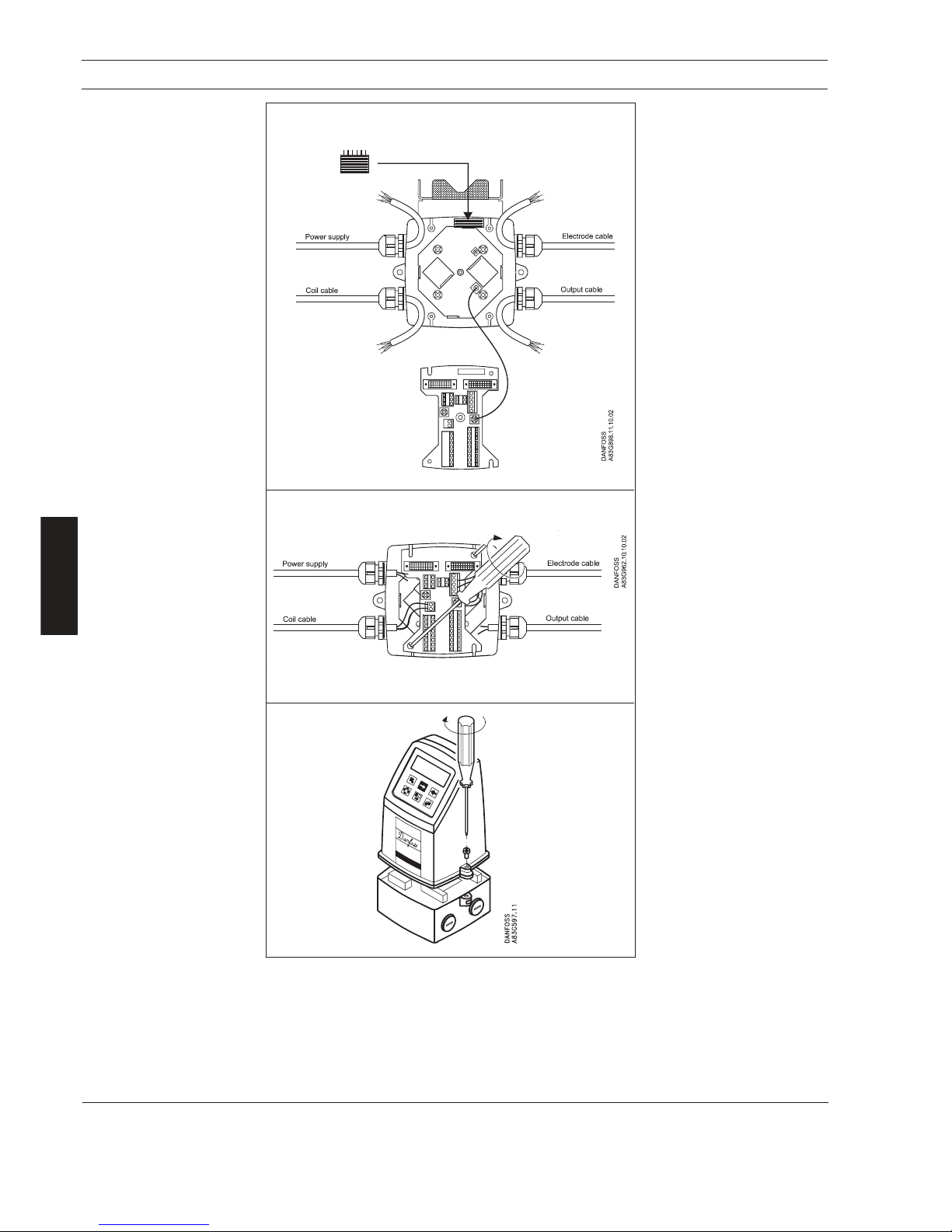
40
MAGFLO
â
Installation of signal
conv.
6. Installation of signal converter
6.2.3
Remote installation
Wall mount
(continued)
Step 4 (wall mounting)
Remove the SENSORPROM
®
unit from the sensor terminal
box. Mount the SENSORPROM® unit in the wall mounting terminal box as shown.
The text on the SENSORPROM
®
unit must face to-
wards the wall bracket.
Mount an earth wire between
PE on the connection board
and bottom of connection box.
Step 5 (wall mounting)
Mount the connection board in
the terminal box. Fix the connection board with the two diagonal opposite screws.
Fit the coil, electrode, supply
and output cables respectively
and tighten the cable glands to
obtain optimum sealing.
Please see the wiring diagram
in section 7 for the electrical
connections.
Step 6 (wall mounting)
Mount the signal converter on
the terminal box.
Remove the SENSORPROM® unit
Page 41

41
MAGFLO
â
Installation of signal
conv.
6. Installation of signal converter
6.2.4
Remote installation
Rack mount
(continued from page 38)
Step 1 + 2
Please refer to page 38.
Step 3 (Rack mount units)
Mount the SENSORPROM® memory unit on the connection board supplied with the signal
converter as shown. The SENSORPROM
®
unit is supplied with the sensor in the terminal box.
Step 4 (Rack mount units)
Mount the guide rails in the rack system as shown. Distance between guide rails is 4.52 inch.
Guide rails are supplied with the rack system and not with the signal converter.
Step 5 (Rack mount units)
Mount the connection board as shown. Board to be mounted on the inside.
Step 6 (Rack mount units)
Connect the cables as shown under "Electrical connection", section 7.
Step 7 (Rack mount units)
Insert the signal converter into the rack system.
(From sensor terminal box)
Page 42

42
MAGFLO
â
Installation of signal
conv.
Locate the add-on module in the bottom of the
MAG 6000 signal converter.
6. Installation of signal converter
6.2.5
Add-on modules
(MAG 6000 only)
Press the add-on module forwards as far as
possible.
The add-on module has now been installed
and the signal converter is ready t o be
installed terminal box.
Page 43

43
MAGFLO
â
Installation of signal
conv.
6. Installation of signal converter
6.2.6
Installation using wall
mounting kit
(continued from page 38)
Step 1 + 2
Please refer to page 38.
Step 3 (Rack mount units)
Mount the NEMA 4X enclosure on the wall with four screws.
Step 4 (Rack mount units)
Mount the SENSORPROM
®
memory unit on the connection board as shown.
The SENSORPROM® unit is supplied with the sensor in the terminal box. The connection board
for NEMA 4X wall mounting boxes must be used (only applicable if parts are bought separate and
not as one unit).
Step 5 (Rack mount units)
Connect the cables to the terminals, see "Electrical connection", section 7.
Step 6 (Rack mount units)
Insert in the signal converter and close the cover.
(From sensor terminal box)
Page 44

44
MAGFLO
â
Installation of signal
conv.
6. Installation of signal converter
6.2.7
Installation using front of
panel mounting kit
(continued from page 38)
Step 1 + 2
Please refer to page 38.
Step 3 (Rack mount units)
Mount the SENSORPROM
®
memory unit on the connection board as shown.
The SENSORPROM® unit is supplied with the sensor in the terminal box.
Step 4 (Rack mount units)
Fit the enclosure in a cut out at the front of a panel. Fasten the four screws accessible at the front.
Step 5 (Rack mount units)
Connect the cables as shown under "Electrical connection", section 7.
Step 6 (Rack mount units)
Insert in the signal converter and close the cover.
(From sensor terminal box)
Page 45
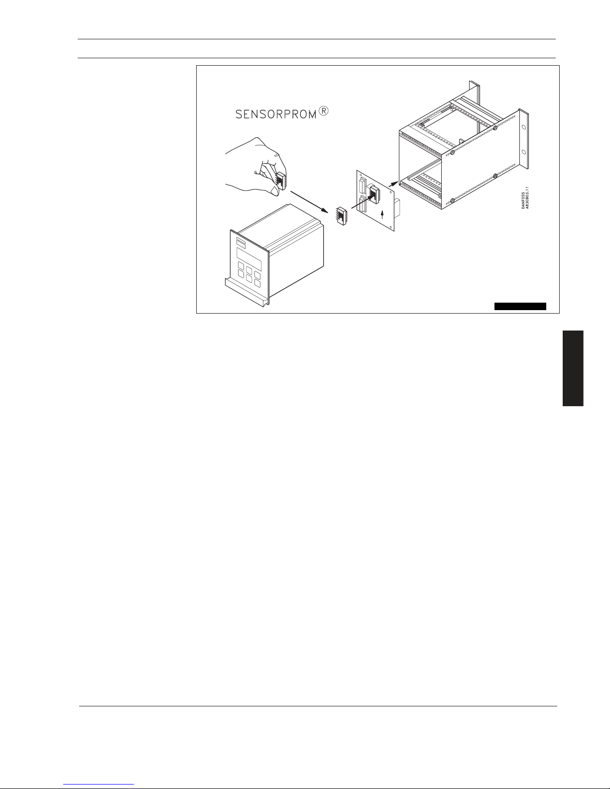
45
MAGFLO
â
Installation of signal
conv.
6.2.8
Installation using back of
panel mounting kit
(continued from page 38)
Step 1 + 2
Please refer to page 38.
Step 3 (Rack mount units)
Mount the SENSORPROM
®
memory unit on the connection board as shown.
The SENSORPROM® unit is supplied with the sensor in the terminal box.
Step 4 (Rack mount units)
Mount the connection board in the back of the enclosure.
Step 5 (Rack mount units)
Connect the cables as shown under "Electrical connection", section 7.
Step 6 (Rack mount units)
Mount the enclosure in the back of a panel with four screws.
Step 7 (Rack mount units)
Insert in the signal converter.
6. Installation of signal converter
(From sensor terminal box)
Page 46
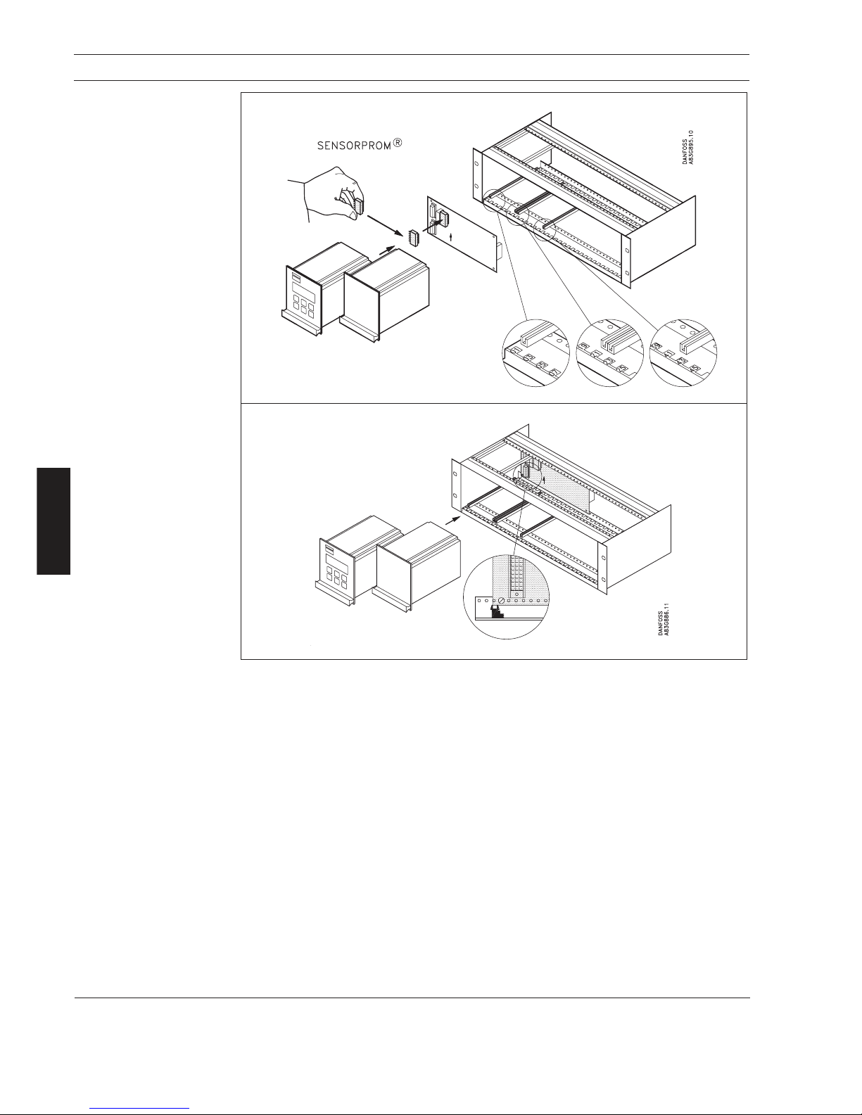
46
MAGFLO
â
Installation of signal
conv.
6. Installation of signal converter
6.3
Signal converter with
safety barrier
(continued from page 38)
Step 1 + 2
Please refer to page 38.
Step 3 (Rack mount units)
Fit the SENSORPROM
®
memory unit on the connection board supplied with the safety barrier.
The SENSORPROM
®
unit is delivered mounted in the terminal box of the sensor. The
connection board supplied with the signal converter is not used.
Step 4 (Rack mount units)
Mount the guide rails in the rack system as shown. Distance between guide rails is 4.52 inch.
Guide rails are supplied with the rack system and not with the signal converter.
Step 5 (Rack mount units)
Mount the connection board as shown. The mounting screw must be installed just in line with the
guide rails.
Step 6 (Rack mount units)
Connect the cables as shown under "Electrical connection", section 7.
Step 7 (Rack mount units)
Insert the signal converter and the safety barrier into the rack system.
(From sensor terminal box)
Page 47
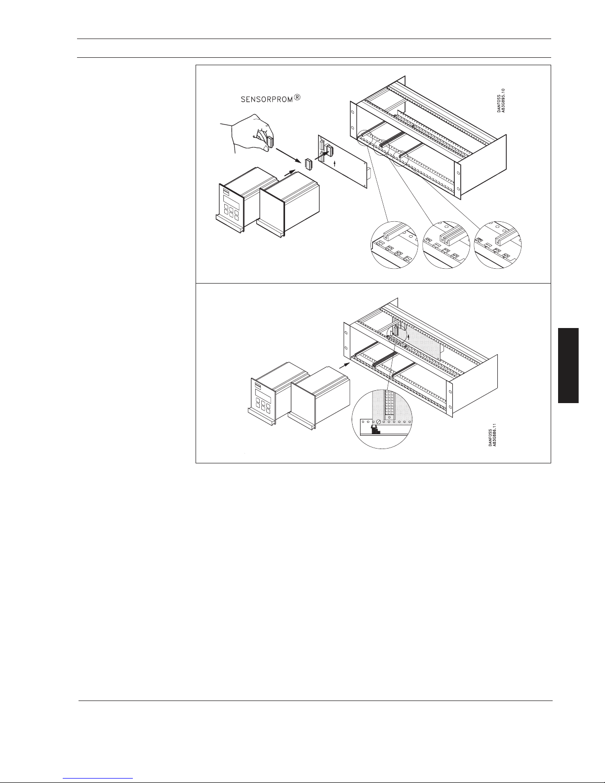
47
MAGFLO
â
Installation of signal
conv.
6.4
Signal converter with
cleaning unit
(continued from page 38)
Step 1 + 2
Please refer to page 38.
Step 3 (Rack mount units)
Fit the SENSORPROM
®
memory unit on the connection board supplied with the cleaning unit.
The SENSORPROM
®
unit is delivered mounted in the terminal box of the sensor. The
connection board supplied with the signal converter is not used.
Step 4 (Rack mount units)
Mount the guide rails in the rack system as shown. Distance between guide rails is 4.52 inch.
Guide rails are supplied with the rack system and not with the signal converter.
Step 5 (Rack mount units)
Mount the connection board as shown. The mounting screw must be installed just in line with the
guide rails.
Step 6 (Rack mount units)
Connect the cables as shown under "Electrical connection", section 7.
Step 7 (Rack mount units)
Select AC-cleaning or DC-cleaning mode at the switch located on the base of the cleaning unit.
Step 8 (Rack mount units)
Insert the cleaning unit and the signal converter in the rack system.
6. Installation of signal converter
(From sensor terminal box)
Page 48

48
MAGFLO
â
7. Electrical connection
Elec.con.
7. Electrical connection
7.1
Signal converter
MAG 5000 and MAG 6000
connection diagram
Grounding
PE must be connected for safety reasons.
Mechanical counters
When connecting a mechanical counter to terminals 57 and 58 (active output), a 1000 mF capacitor
must be connected to the terminals 56 and 58. Capacitor + is connected to terminal 56.
Output cables
When using long cables in an electrically noisy environment we recommend using shielded cable
in metal conduit. See page 15 for max. cable lengths.
Electrode cables
Dotted connections only to be used when using speical cable.
Special cable with individual wire shields (shown
with dashed lines) are only
required when using empty
pipe function with low
conductivity process (see
“Specifications, section 2)
Safety Note
Only qualified personnel
should perform wiring or
repairs, and only when the
signal converter is not
powered. Install signal
converter in accordance
with all relevant NEC and
local codes.
Page 49

49
MAGFLO
â
7. Electrical connection
Elec.con.
7.2
Wiring diagram for signal
converter and sensor
7.2.1 Integral installation
Integral mount
Remote wall mounting
7.2.2
Remote installation wall
mount NEMA 6 enclosure
Cathodic protected piping
Integral mount installation:
The signal converter must be supplied through an isolation transformer. The terminal "PE" must
not be connected.
Sensor cables
· Unshielded cable ends must be as short as possible and the two cables must be kept separate.
Cables must not be spliced.
· Terminals 81 and 84 are only connected when double shielded is used. See 2.7.1.
· Coil cable shield must be connected at both ends. Electrode cable shields must be connected
at sensor side only.
Note
See 5.3 when using cathodic protection.
Note
Mount a grounding wire to the PE on the connnection board to ensure sufficient grounding.
Page 50

50
MAGFLO
â
7. Electrical connection
Elec.con.
7.2.3
Rack mount
NEMA 2 enclosure
7.2.4
Wall mount
NEMA 4X
enclosure
7.2.5
Rack mount with
safety barrier
NEMA 2
EEx (ia/ib)
up to 12''
Page 51

51
MAGFLO
â
7. Electrical connection
Elec.con.
7.2.6
Wall mount with
safety barrier
NEMA 6
EEx (ia/ib) up to
12''
7.2.7
Rack mount
NEMA 2 with
cleaning unit
7.2.8
Wall mount
NEMA 6 with
cleaning unit
Page 52

52
MAGFLO
â
8. Start-up & programming
Start-up & programming
8. Commissioning
8.1
Keypad and
display layout
Keypad The keypad is used to program the flowmeter. The function of the keys is as follows:
TOP UP KEY This key (hold 2 sec.) is used to switch between operator
menu and setup menu. In the converter setup menu, a short
press will cause a return to the previous menu.
FORWARD KEY This key is used to step forward through the menus. It is the
only key normally used by the operator.
BACKWARD KEY This key is used to step backward through the menus.
CHANGE KEY This key changes the settings or numerical values.
SELECT KEY This key selects the figures to be changed.
LOCK/UNLOCK KEY This key allows the operator to change settings, save
changes and gives access to submenus.
Display
The display is alphanumerical and indicates flow values, flowmeter settings and error messages.
The upper line is for primary flow readings and will always show either flow rate, totalizer 1 or totalizer
2. The line is divided into 3 fields.
S: Sign field
P: Primary field for numerical value
U: Unit field
The centre line is the title line (T) with individual information according to the selected operator or
setup menu.
The lowest line is the subtitle line (ST) which either will add information to the title line or keep
individual information independent of the title line.
F: The alarm field. Two flashing triangles will appear by a fault condition.
M: The mode field. The symbols indicate the following.
Communication mode Basic settings Operator active
Service mode Output Operator inactive
Operator menu External input
Product identity Sensor characteristics
Language mode Reset mode
Ready for change Access to submenu
Value locked (saved) RESET MODE: Zero setting of
totalizers and initialization of setting
L: The lock field. Indicates the function of the lock key.
Page 53

53
MAGFLO
â
8. Start-up & programming
Start-up & programming
8.2
Menu build-up
The menu structure of a specific signal converter type is shown in a menu overview map.
Details of how a specific parameter is set is shown in a menu detail map for the specific parameter.
A detail map is valid for each type of signal converter if not indicated otherwise. The menu structure
is valid for the title and subtitle line only. The upper line is for primary readings only and will always
be active with either flowrate, totalizer 1 or totalizer 2.
The menu is built up in two parts. An operator menu and a setup menu.
Operator menu
The operator menu is for daily operation. The operator menu is customised in the operator menu
setup. The signal converter always starts in operator menu No. 1. The page forward and page
backward keys are used to step through the operator menus.
Setup menu
The setup menu is for start-up commissioning and service only.
Access to the setup menu is gained by pressing the top up key for 2 seconds. The setup menu
operates in two modes:
· View mode
· Setup mode
View mode is a read only mode. The pre-selected settings can only be viewed.
Setup mode is a read and write mode. The pre-selected settings can be scanned and changed.
Access to the setup mode is password protected. The factory set password is 1000 (see 8.6.1).
Access to a submenu in the set up menu is gained by the lock key. A short press on a top up key
will bring you back to the previous menu. A long press (2 sec.) on the top up key will exit the setup
menu and bring you back to operator menu No. 1.
8.2.1
Password
The SETUP MENU can be operated in two different modes:
1. VIEW MODE (Read only)
2. CHANGE MODE (Read and write mode)
Access view mode is gained by pressing the forward key when in the password menu.
Access to change mode is password protected. The password is factory set to 1000, but can be
changed to any value between 1000 and 9999 in the change password menu.
The factory setting of 1000 can be re-established as follows:
· Switch off power suppply
· Press the TOP UP key and switch on the power supply
· Release the key after ROM and RAM tests are completed
The password is now reset to 1000.
Page 54

54
MAGFLO
â
8. Start-up & programming
Start-up & programming
8.3.1 MAG 5000 and MAG 6000
Menu overview
Page 55

55
MAGFLO
â
8. Start-up & programming
Start-up & programming
8.3.2 MAG 6000 CT
Menu overview
Page 56

56
MAGFLO
â
8. Start-up & programming
Start-up & programming
Menu detail
8.4.1
Basic settings
Comma for flow rate, totalizer 1 and totalizer 2 can be individually positioned.
· open the respective window.
· ensure that the cursor is positioned below the comma. Use the SELECT KEY .
· move the comma to the requested position. Use the CHANGE KEY .
Units are changed by means of the CHANGE KEY with the cursor placed below the unit selected.
Select units (cursor moved) by means of the SELECT KEY .
Totalizer 2 is not visible when batch is selected as digital output.
Main frequency
To select the main power supply frequency corresponding
to the country in which the flowmeter is installed.
(US = 60 Hz)
Flow direction
Select the correct flow direction in the pipe
Q
max.
Sets the measuring range, the analog outputs and the
frequency output. Value, decimal point, unit and time can
be set individually (setting is dimension dependent).
Q
max.
2
Sets the measuring range, the analog outputs and the
frequency output. Value, decimal point, unit and time can
be set individually (setting is dimension dependent).
Only visible when it has been choosen as external digital
input.
Totalizers
To set unit and decimal point.
Low flow cutt off
To set a % of selected Q
max.
. To filter noise in the
installation. Influences display and all outputs.
Error level
To select which error level, the flowmeter will detects an
error.
Page 57

57
MAGFLO
â
8. Start-up & programming
Start-up & programming
Menu detail
8.4.3
Digital and relay outputs
Error level
Error number
8.4.2
Outputs
Digital output
Frequency
Proportional to flowrate
(Terminal 56, 57, 58)
The current output must be turned off when not used.
Current output
Proportional to flowrate
(Terminal 31 and 32)
4 - 20 mA + alarm:
Current output gives the following mA, depending on what is selected as error level in basic settings.
Fatal: 1 mA, permanent: 2 mA, warning: 3 mA
Digital output
Pulse/volume
(Terminal 56, 57, 58)
Page 58

58
MAGFLO
â
8. Start-up & programming
Start-up & programming
Menu detail
Limit/direction
Limit switches are available for both digital as well as relay output.
Direction mode: 1 set point at 0% flow; hysteresis 5%.
If 2 set points must activate 2 separate outputs, a single set point has to be selected individually
for digital as well as relay outputs.
Batch
(MAG 6000 only)
(Possible through relay and
digital output)
8.4.4
Relay output
Cleaning
8.4.5
External input
Batch control is available on MAG 6000 only.
The relay output must always be used to operate the cleaning unit when a cleaning unit has been
installed together with the signal converter. The relay output cannot be used for other purposes.
Page 59

59
MAGFLO
â
8. Start-up & programming
Start-up & programming
Menu detail
8.4.6
Sensor characteristics
8.4.7
Reset mode
If “SENSORPROM not
installed” is shown, refer to
section 6 (depending on
type of mounting configuration).
Page 60
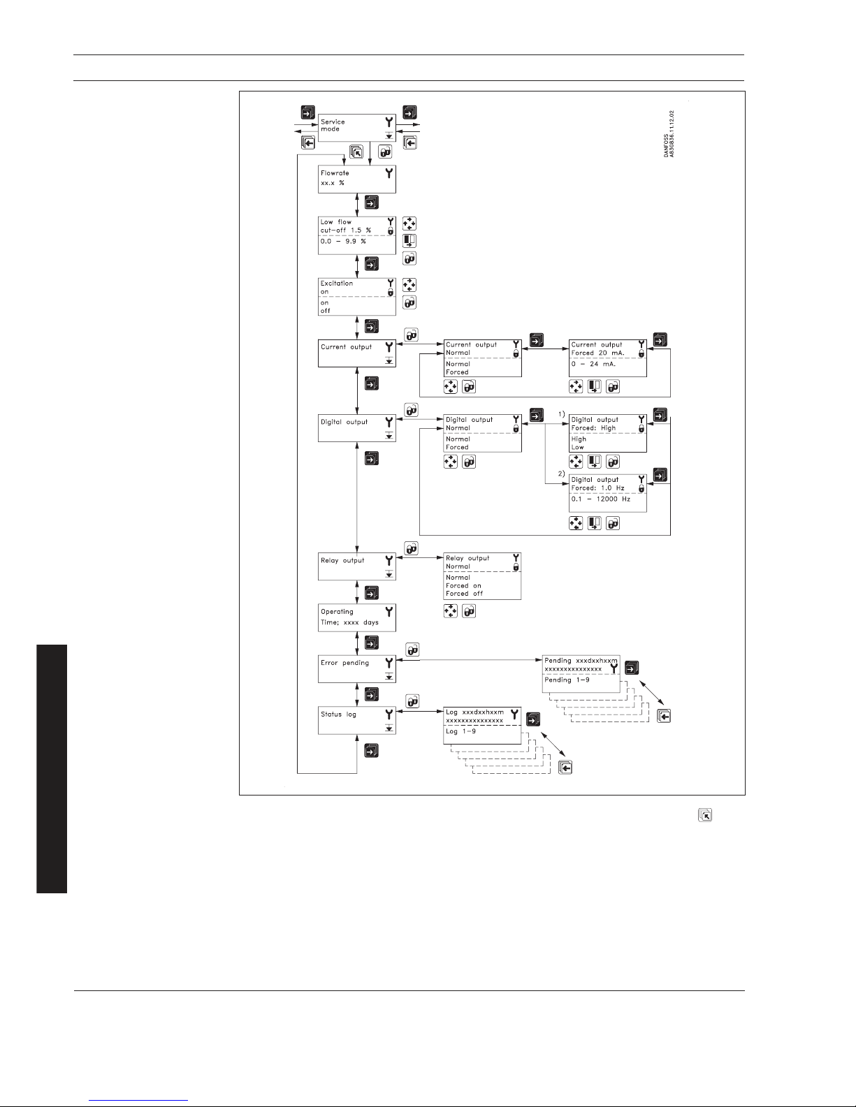
60
MAGFLO
â
8. Start-up & programming
Start-up & programming
8.4.8
Service mode
All previous settings are reinitialized when service mode is exited using the top up key .
The error system
The error system is divided into an error pending list and a status log list. Time is displayed as days,
minutes and hours since the error has occurred. The first 9 standing errors are stored in error
pending. When an error is removed it is removed from error pending. The latest 9 errors are stored
in the status log. When an error is removed it is still kept in status log. Errors in status log is stored
for 180 days.
Error pending and status log are accessible when enabled in the operator menu.
Menu detail
1) Standard
2) If digital output is set to
frequency
Page 61

61
MAGFLO
â
8. Start-up & programming
Start-up & programming
Menu setup
8.4.9
Operator menu setup
The upper line is always active and can never be deselected.
The two lower lines are for individual operator information. Information which the operator can scroll
through with the forward key .
· A closed lock key in the operator menu setup, means that the menu is enabled when viewing
the operator menu.
· An open lock key symbol , means that the menu is not available in the operator menu.
The middle line can either be used as a heading “Text line” for the lower line, or as a flow-reading.
A flow reading can be individually selected for each menu.
The lower line may be used for an additional flow reading to the reading already available in the
upper line.
Text means that the text for the chosen measured value is
show n.
For exam ple if tex t is chosen in lin e 2 and flow rate is
chosen in line 3, the text “flow rate” is shown in line 2 and
the measured flow rate value is show in line 3.
Page 62

62
MAGFLO
â
8. Start-up & programming
Start-up & programming
8.4.10
Product identity
(Read only)
Software version of add-on module is only available if the add-on module has been installed.
Menu detail
8.4.11
Change password
If you have forgotten your password please
refer to 8.2.1 on how to reset your password
back to factory setting, 1000.
Page 63

63
MAGFLO
â
8. Start-up & programming
Start-up & programming
8.4.12
Language mode
Menu detail
8.4.13
HARTâ communication
MAG 5000 HART or as
add-on module
Used to select language.
Page 64

64
MAGFLO
â
8. Start-up & programming
Start-up & programming
8.5.3
Batch
(Only available on
MAG 6000)
A batch can be started, paused or stopped from the operator menu, in addition to the externally
operated batch control. The batch is controlled using the lock and the top up keys.
The lock key :
· Starts the batch
· Holds the batch (pause) when pressed during batching
· Restarts the batch to continue when pressed during a pause.
The top up key resets a batch completely during a pause.
The accumulated number of performed batches can be viewed when enabled in the operator menu
setup, please refer to 8.4.9.
The batch cycle counter is reset by pressing the lock key in the “batch cycle counter reset” menu.
Batch cycle counter
Batch cycle counter reset
8.5.1
Operator menu
Flow rate
Operator menu
The 1st display line is always active and shows the value enabled in the operator menu setup.
· Flow rate
· Totalizer 1
· Totalizer 2
The 2
nd
and 3rd display lines are individually set in the operator menu. The page forward key steps
through the enabled settings.
· Flow rate
· Totalizer
· Totalizer reset
· Batch control
· Batch cycle counter
· Batch cycle counter reset
· Pipe size
· Sensor type
· Pending errors
· Status log
· Tag No.
8.5.2
Totalizer reset
Totalizer
A totalizer is reset by pressing the lock key when the corresponding totalizer reset window is open.
Page 65

65
MAGFLO
â
8. Start-up & programming
Start-up & programming
8.6.1
Factory settings/available
settings
Parameter Factory settings Available settings
Password
Default value 1000
Password 1000 1000 - 9999
Basic settings
Flow direction Positive Positive, negative
Q
max.
(1+2)
- Volume units Dim. dependent m3, ml, l, kl, hl, Ml, ft3, in3, US G, US kG, US MG, UK G,
UK MG
- Time units Dim. dependent Sec., min., hour, day
Totalizer 1 Forward Forward, reverse, net
- Totalizer 1 units Dim. dependent m3, ml, l, kl, hl, Ml, ft3, in3, US G, US kG, US MG,
UK G, UK MG
Totalizer 2 Reverse Forward, reverse, net
- Totalizer 2 units Dim. dependent m3, ml, l, kl, hl, Ml, ft3, in3, US G, US kG, US MG,
UK G, UK MG
Low flow cut-off 1.5 % 0 - 9.9 %
Empty pipe Off Off, on
Error level Warning Fatal, permanent, warning
Output
Current output Off On/off, uni-/bidirectional, 0/4 - 20 mA
- Direction Uni-directional Uni-/bidirectional
- Function 4-20 mA 0-20 mA, 4-20 mA, 4-20 mA + alarm
- Time constant 5 s 0.1 - 30 s
Digital output Pulse Error, direction/limit, batch1), frequency, pulse, error no.,
off
Relay output Error Error, direction/limit, cleaning, error No., off
Direction/limit switch O ff 1 set point/2 set points, - 100 - 100%
- Hysteresis 5% 0.0 - 100%
Batch
1)
Off
- Batch quantity 0 Dim. dependent
- Batch compensation 0 -100 - 100 m
3
- Batch counter Down Up/down
- Time constant 0.1 s 0.1 - 30 s
Frequen cy Off 500 Hz, 1 kHz, 5 kHz, 10 kHz
- Time constant 5 s 0.1 - 30 s
Pulse On
- Pulse polarity Positive Positive/negative
- Pulse width 66 ms 64 µs, 130 µs, 260 µs, 510 µs, 1.0 ms, 2.0 ms,
4.1 ms, 8.2 ms, 16 ms, 33 ms, 66 ms, 130 ms,
260 ms, 520 ms, 1.0 s, 2.1 s, 4.2 s.
- Volume/pulse Dim. dependent Dim. dependent
- Time constant 0.1 s 0.1 - 30 s
Electrode cleaning Off Off/cleaning
- Cleaning cycle time 24 h 1 - 240 h
External input
External input Off Batch, reset totalizer, freeze output, forced output, off
- Batch Start, hold/continue, stop, Q
max.
2
Sensor characteristics
Correction factor 1 0.85 - 2.00
Language English English, German, French, Danish, Swedish, Finnish,
Spanish, Russian, Italian, Portuguese
Operator menu
Primary field Flow rate Flow rate, Totalizer 1, Totalizer 2
Title/subtitle line Flow rate, Totalizer 1, Flow rate, Flow rate %, Q
max.
, Totalizer 1, Totalizer 2,
totalizer 2, totalizer 1 Totalizer 1 reset, Totalizer 2 reset, Batch start/
reset, totalizer 2 reset, paused/stop, Batch cycle counter, Batch cycle
error pending counter reset, Sensor size, Sensor type, Error
pending, Status log, Tag No.
The signal converter is delivered with factory settings ready to measure the actual flow.
1)
Batch is available on
MAG 6000 only
Page 66

66
MAGFLO
â
8. Start-up & programming
Start-up & programming
8.6.2
Dimension dependent
factory settings
MAG 5000 and
MAG 6000
Volume/pulse or batch quantity
US G min. US G max.
1
/
2
0.0000388 1,019
1 0.0000144 2,826
11/
2
0.000277 7,264
2 0.000433 11,333
21/
2
0.000732 19,152
3 0.00111 29,058
4 0.00173 47,022
5 0.0027 70,798
6 0.0039 101,970
8 0.0069 181,222
10 0.0011 283,192
12 0.016 407,881
14 0.021 555,289
16 0.028 725,152
18 0.035 917,733
20 0.043 1,133,034
24 0.062 1,631,791
28 0.085 2,220,894
32 0.110 2,900,873
36 0.140 3,671,199
40 0.173 4,532,400
48 0.249 6,526,635
78 0.692 181,129,860
8.6.3
Dimension dependent
batch and pulse output
settings
MAG 1100
MAG 3100
(ANSI #150, ANSI#300
and AWWA flanges)
Q
ma x.
MAG 5100 W MAG 1100,
3100, 3100 W Volume/ Pulse Totalizer
[in ches] fac.set. min. max. min. max. un it pulse unit unit
1
/
4
1.5 - - 0.11 4.4 US GPM 1 US G US G
3
/
8
4.0 - - 0.31 12.4 US GPM 1 US G US G
1
/
2
10 - - 0.7 28.0 US GPM 1 US G US G
1 25 - - 1.9 77.8 US GPM 1 US G US G
11/
2
60 - - 5.3 198.1 US GPM 1 US G US G
2 100 - - 7.9 308.2 US GPM 1 US G US G
21/
2
160 - - 13.2 523.9 US GPM 1 US G US G
3 250 - - 20.3 792.5 US GPM 1 US G US G
4 400 - - 31.3 1,241.6 US GPM 1 US G US G
1
/
2
10 - - 0.7 28.0 US GPM 1 US G US G
1 25 1.9 77.8 1.9 77.8 US GPM 1 US G US G
11/
2
60 5.3 198.1 5.3 198.1 US GPM 1 US G US G
2 100 7.0 277.4 7.9 308.2 US GPM 1 US G US G
21/
2
160 11.0 440.3 13.2 523.9 US GPM 1 US G US G
3 250 17.6 704.5 20.3 792.5 US GPM 1 US G US MG
4 400 27.7 1,100.7 31.3 1,241.6 US GPM 1 US G US MG
5 600 44.0 1,761.1 48.9 1,941.6 US GPM 1 US G US MG
6 900 70.4 2,773.8 70.4 2,800.2 US GPM 1 US G US MG
8 1,500 110.1 4,402.8 124.6 4,975.2 US GPM 1 US G US MG
10 2,500 176.1 7,044.5 194.6 7,779.8 US GPM 1 US G US MG
12 3,500 277.4 11,007.1 280.5 11,200.8 US GPM 1 US G US MG
14 4,500 381.3 15,247.0 381.3 15,247.0 US GPM 1 US G US MG
16 6,000 498.0 19.914.0 498.0 19,914.0 US GPM 1 US G US MG
18 7,500 630.5 25,206.2 630.5 25,206.2 US GPM 1 US G US MG
20 9,500 778.4 31,119.2 778.4 31,119.2 US GPM 1 US G US MG
24 13,500 1,120.5 44.812.0 1,120.5 44,812.0 US GPM 10 US G US MG
28 18,500 1,525.1 60.996.9 1,525.1 60.996.9 US GPM 10 US G US MG
30 21,000 1,751.0 70,022.7 1,751.0 70,022.7 US GPM 10 US G US MG
32 24,000 1,991.8 79.669.3 1,991.8 79,669.3 US GPM 10 US G US MG
36 30,000 2,522.8 100,833.7 2,522.8 100,833.7 US GPM 10 US G US MG
40 37,000 3,112.8 124,485.7 3,112.8 124,485.7 US GPM 10 US G US MG
42 37,000 3,112.8 124.485.7 US GPM 10 US G US MG
44 45,000 3,765.7 150.625.3 3,765.7 150,625.3 US GPM 10 US G US MG
48 53,000 4,482.1 179.261.4 4,482.1 179,261.4 US GPM 10 US G US MG
54 73,000 - - 6,100.1 243,991.8 US GPM 1000 US G US MG
60 84,000 - - 7,002.7 280,095.0 US GPM 1000 US G US MG
66 95,000 - - 7,967.4 318,685.9 US GPM 1000 US G US MG
72 120,000 - - 10,083.8 403,334.8 US GPM 1000 US G US MG
78 140,000 - - 12,449.0 497,947.2 US GPM 1000 US G US MG
Page 67

67
MAGFLO
â
8. Start-up & programming
Start-up & programming
Internal totalizers
Depending on type of approval it is possible to reset the internal totalizers. The type of approval is
selected in the reset menu, with the hardware key mounted. It is possible to select between:
· Hot/cold water
· Other liquids
Resetting of totalizers by electrical input is not possible.
Hot/cold water
· Totalizer 1 is allocated to forward flow (cannot be reset).
· Totalizer 2 is allocated to reverse flow (cannot be reset).
Other liquids
Both totalizer 1 and totalizer 2 are allocated to measure the net forward flow, i.e. any reverse flow
will make the totalizers count backwards.
· Totalizer 1 is consecutive and cannot be reset.
· Totalizer 2 can be reset if the flow velocity in the meter pipe is <0.75 ft./s. When the totalizer is
reset, the pulse output register will also be reset.
Setting primary operating parameters such as Q
max.
, low flow cut-off, units, approvals, etc. is blocked
during normal operation. See menu setup.
These settings are made in connection with commissioning or calibration by mounting a hardware
key on solder terminals of the connection plate of the signal converter. When the key is mounted,
the terminals are shorted, providing access to all menu items. When the key is removed, the primary
settings are blocked in accordance with the requirements in the authorisation.
8.6.4
MAG 6000 CT settings
Output
· When selecting hot water, the output settings are not allowed and menu will not be shown on
display.
· When selecting cold water or other liquids, all output settings can be changed.
Page 68

68
MAGFLO
â
8. Start-up & programming
Start-up & programming
Error system
The converter system is equipped with an error and status log system with 4 groups of information.
· Information without a functional error involved
· Warnings which may cause malfunction in the application. The cause of the error may disappear
on its own
· Permanent errors which may cause malfunction in the application. The error requires an operator
· Fatal error which is essential for the operation of the flowmeter
2 menus are available in service and operator menus for registration of information and errors
· Error pending
· Status log
Error pending
The first 9 standing errors are stored in “error pending”. When an error is removed it is removed from
“error pending”.
The acceptance level for “error pending” can be individually configured to a particular application.
The acceptance level is set in the “basic settings” in the converter setup menu.
Acceptance levels
· Fatal error: Fatal errors are registered as errors
· Permanent errors: Permanent and fatal errors are registered as errors
· Warning (Default value): Warnings, permanent and fatal errors are registered as errors
The error information is displayed in the title and subtitle line. The title line will show the time since
occurrence of error. The subtitle line will flash between an error text and a remedy text. The error
text will indicate type of error (I, W, P or F), error No. and error text. The remedy text will inform the
operator of the action to take to remove the error.
Status Log
Like “error pending” except that information, warnings, permanent and fatal errors is always stored
in the “status log”. The “status log” stores the latest 9 messages received/registered during the last
180 days.
Alarm field
The alarm field on the display will always flash with an error pending.
Error output
The digital and relay output can individually be activated error by error (error level). The relay output
is default selected to error level. An output can also be selected to activate on a single error number.
The alarm field, error output and error pending always operate together.
The analog output turns to a 1 mA level when in the 4-20 mA mode.
Operator menu
Error pending and status log are as default enabled in the operator menu.
8.7.1
Error handling
Page 69

69
MAGFLO
â
8. Start-up & programming
Start-up & programming
Error Error text #Comment Outputs Input
No. Remedy text status status
1 I1 -
Power on
OK Power on has happened Active Active
2 I2 -
Add-on module
Applied A new module has been applied to the system Active Active
3 I3 -
Add-on module
Install An add-on module is defect or has been removed.
This can be an internal add-on module Active Active
4 I4 -
Param. corrected
OK A less vital parameter in the converter has been re-
placed by its default value Active Active
20 W20 -
Totalizer 1
Reset manually During initialisation the check of the saved totalizer
value has failed. It is not possible to rely on the
saved totalizer value anymore. The totalizer value
must be reset manually in order to rely on future
readings Active Active
20 W20 -
Totalizer 2
Reset manually During initialisation the check of the saved totalizer
value has failed. It is not possible to rely on the
saved totalizer value anymore. The totalizer value
must be reset manually in order to rely on future
readings Active Active
21 W21 -
Pulse overflow
Adj. pulse settings Actual flow is too big compared with pulse width and Reduced
volume/pulse pulse width Active
22 W22 -
Batch timeout
Check installation Duration of batching has exceeded a predefined Batch out-
max. time put on zero Active
23 W23 -
Batch overrun
Check installation Batch volume has exceeded a predefined maximum Batch out-
overrun volume put on zero Active
24
W24 - Batch neg. flow
Check flow direction Negative flow direction during batch Active Active
30 W30 -
Overflow
Adj. Q
max.
Flow is above Q
max.
settings Max. 120 % Active
31 W31 -
Empty pipe
Pipe is empty Zero Active
40 P40 -
SENSORPROM
â
Insert/change SENSORPROMâ unit not installed Active Active
41 P41 -
Parameter range
Switch off and on A parameter is out of range. The parameter could not
be replaced by its default value. The error will disappear at the next power-on Active Active
42 P42 -
Current output
Check cables Current loop is disconnected or the loop resistance
is too big Active Active
43 P43 -
Internal error
Switch off and on Too many errors occured at the same time
Some errors are not detected correctly Activ e A cti ve
44 P44 -
CT SENSORPROM
â
SENSORPROMâ unit has been used as CT version Active Active
60 F60 -
CAN comm. error
Converter/AOM CAN bus communication error. An add-on module, the
display module or the converter is defect Zero Inac tive
61 F61 -
SENSORPROMâ error
Replace It is not possible to rely on the data in SENSOR-
PROMâ unit anymore Active Ac tiv e
62 F62 -
SENSORPROMâ ID
Replace The SENSORPROMâ unit ID does not comply with the
product ID.
The SENSORPROM
â
unit is from another type of
product MASSFLOâ, SONOFLOâ etc. Zero In acti ve
63 F63 -
SENSORPROM
â
Replace It is not possible to read from the SENSORPROM
â
unit anymore. Active Act ive
70 F70 -
Coil current
Check cables Coil excitation has failed Active Active
71 F71 -
Internal error
Replace converter Internal convertion error in ASIC Active Active
8.7.2
List of error numbers
Page 70

70
MAGFLO
â
9. Service
Commissioning
9. Service
Power on converter,
display light on
YES
NO
NO
Check cables/connections
Check connection board
Check pins in converter
multiplug - OK
Correct fault
YES
NO
Output
readings OK
Converter
defective
YES
Display defect
Change display
Output and display
readings OK ?
NO
NO
Check cables/connections
Check connection board
Check pins in converter
multiplug - OK
Correct fault
Error triangles flashing
NO
YES
Check error table
Converter OK Check settings/application
Check installation/sensor/
grounding connection etc.
YES
YES
Often problems with unstable/wrong measurements occur due to insufficient/wrong grounding or
potential equalization. Please check connection. If OK, the MAGFLOâ converter can be checked
as described under 9.1 and sensor under 9.3.
9.1
Converter check list
When checking MAGFLOâ installations for malfunction the easiest method to check the signal
converter is to replace it with another MAG 5000/6000 converter with a similar power supply.
A replacement can easily be done as all settings are stored in and downloaded from the
SENSORPROM
â
unit - no extra settings need to be made.
If no spare converter is available - then check converter according to check table.
Page 71

71
MAGFLO
â
9. Service
Commissioning
9.2
Trouble shooting
MAG 5000 and MAG 6000
Symp tom O utput Error Cause Re med y
sign als code
Empty display Minimum 1. No power supply Power supply
Check MAG 5000/6000 for
bended pins on the connector
2. MAG 5000/6000 defective Replace MAG 5000/6000
No flow signal Minimum 1. Current output disabled Turn on current output
2. Digital output disabled Turn on digital output
3. Reverse flow direction Change direction
F70 Incorrect or no coil current Check cables/connections
W31 Measuring pipe empty Ensure that the measuring
pipe is full
F60 Internal error Replace MAG 5000/6000
Und efined P42 1. No load on current output Check cables/connections
2. MAG 5000/6000 defective Replace MAG 5000/6000
P4 1 Initializing error Switch off MAG 5000/6000,
wait 5 s and switch on again
Indicates flow Unde fined Measuring pipe empty Select empty pipe cut-off
with no flow Empty pipe cut-off is OFF Ensure that the measuring
in pipe pipe is full
Electrode connection missing/ Ensure that electrode cable
electrode cable is insuffi- is connected and sufficiently
ciently screened scree ned
Unstable Unst abl e 1. Pulsating flow Increase time constant
flow signal 2. Conductivity of medium Use special electrode cable
too low
3. Electrical noise potential Ensure sufficient potential
between medium and eq ual iza tio n
sen sor
4. Air bubbles in medium Ensure medium does not
contain air bubbles
5. High concentration of par- Increase time constant
ticles or fibres
Measuring error Undefi ne d Incorrect installation Check installation
P4 0 No SENSORPROMâ unit Install SENSORPROMâ unit
P4 4 CT SENSORPROM
â
unit Replace SENSORPROMâ unit
or reset SENSORPROM
â
unit
with MAG CT converter
F61 Deficient SENSORPROM
â
Replace SENSORPROMâ unit
unit
F62 Wrong type of SENSOR- Replace SENSORPROM
â
unit
PROMâ unit
F63 Deficient SENSORPROM
â
Replace SENSORPROMâ unit
unit
F71 Loss of internal data Replace MAG 5000/6000
Maximum W30 Flow exceeds 100% of Q
max.
Check Q
max.
(Basic Settings)
W21 Pulse overflow
· Volume/pulse too small Change volume/pulse
· Pulse width too large Change pulse width
Measuring Missing one electrode Check cables
approx. 50% connec tion
Loss of totalizer OK W20 Initializing error Reset totalizer manually
data
##### OK Totalizer roll over Reset totalizer or increase
Signs in display totalizer unit
Page 72

72
MAGFLO
â
9. Service
Commissioning
ATTENTION!
If there is leakage from MAG 1100/3100/3100 W or MAG 5100 W and the unit has been used
to measure inflammable/explosive liquids, there might be a risk of explosion when checking
with a megger.
9.3
Check list MAG sensor
Disconnect all leads to MAG 1100/3100/3100 W or MAG 5100 W
MAG 1100/3100/3100 W or MAG 5100 W installed and filled with the medium:
Check coil resistance with a multimeter
R 85-86 Nominal value: See table
Check coil insulation with a megger (500 V)
R 85 - Gnd Nominal value: Infinite resistance
Check electrode circuit with a moving-coil instrument without amplifier (measurement unstable)
R 82 - Gnd Nominal value: 5-500 kohm
R 83 - Gnd Nominal value: 5-500 kohm
Sensor apparently OK.
Remove sensor, dry it and check.
Sensor may be defective.
Contact Danfoss
Dirty electrodes or
conductivity too low
NO
NO
> 500 kohm
< 500 kohm
YES
YES
MAG 1100/3100/3100 W
or MAG 5100 W
removed from system – empty and dry:
Check coil resistance with a multimeter
R 85-86 Nominal value: See table
Check coil insulation with a megger (500 V)
R 85 - Gnd Nominal value: Infinite resistance
Check electrode insulation with megger (500 V)
R 82 - Gnd Nominal value: Infinite resistance
R 83 - Gnd Nominal value: Infinite resistance
NO
NO
YES
YES
MAG 1100/3100/3100 W or MAG 5100 W OK
YES
Check continuity between electrode and electrode
terminal
R 82 - Electrode Nominal value: 0 kohm
R 83 - Electrode Nominal value: 0 kohm
YES
Sensor may be defective.
Contact Danfoss
NO
NO
Page 73

73
MAGFLO
â
9. Service
Commissioning
9.4
Coil resistance table
Coil resistance for MAG 1100, MAG 1100 PFA = 98 ohms +/- 4 ohm
Note
On MAG 1100 ½” produced as from May 1999 the coil resistance must be 86 ohm, +8/-4 ohm.
All resistance values are at 7 °F.
The resistance changes proportionally 0.22 %/°F.
Coil resistance
MAG 3100 MAG 3100 W MAG 5100 W
Inches Resistance Size inches Ohms Tolerance Ohms Tolerance
1
/
2
104 15 104 +/- 2 104 +/- 2
1 104 1 104 +/- 2 104 +/- 2
11/
2
92 1 92 +/- 2 92 +/- 2
2 92 2 92 +/- 2 124 +/- 4
21/
2
100 21/
2
100 +/- 2 127 +/- 4
3 94 3 94 +/- 2 126 +/- 4
4 92 4 92 +/- 2 125 +/- 4
5 92 5 92 +/- 2 126 +/- 4
6 94 6 94 +/- 2 116 +/- 4
8 90 8 90 +/- 2 109 +/- 4
10 92 10 92 +/- 2 104 +/- 4
12 100 12 100 +/- 2 108 +/- 4
14 112 14 112 +/- 2 112 +/- 2
16 100 16 100 +/- 4 100 +/- 4
18 108 18 108 +/- 4 108 +/- 4
20 122 20 122 +/- 4 122 +/- 4
24 115 24 114 +/- 4 114 +/- 4
28 128 28 112 +/- 4 112 +/- 4
30 133
32 128 32 127 +/- 4 127 +/- 4
36 131 36 93 +/- 4 93 +/- 4
40 131 40 103 +/- 4 103 +/- 4
44 126
48 130 48 124 +/- 4 124 +/- 4
54 130
60 124
66 133
72 133
78 147
Page 74

74
MAGFLO
â
Ordering
Description Size Code No. Symbol
MAG 1100
1
/4" 083G4044
Ceramic Al2O
3
3
/8" 083G4046
Temperature of medium max. 300°F
1
/2" 083G4047
Included: 1" 083G4049
2 EPDM gaskets, studs and nuts 11/2" 083G4051
2" 083G4052
21/2" 083G4053
3" 083G4054
4" 1) 083G4055
MAG 1100
3
/8" 083G5046
PFA-liner
1
/2" 083G5047
Temperature of medium max. 300°F 1" 083G5049
Included: 11/2" 083G5051
2 EPDM gaskets, studs and nuts 2" 083G5052
21/2" 083G5053
3" 083G5054
4" 1) 083G5055
MAG 1100 (High temperature)
1
/2" 083G4057
Ceramic Al2O
3
1" 083G4059
Temperature of medium max. 390°F 11/2" 083G4061
Included: 2" 083G4062
2 graphite gaskets, studs and nuts 3" 083G4064
4" 1) 083G4065
MAG 1100 Ex
1
/
4
083G4024
Ceramic Al2O
3
3
/8" 083G4026
Temperature of medium max. 250°F
1
/2" 083G4027
Included: 1" 083G4029
2 EPDM gaskets, studs and nuts 11/2" 083G4031
2" 083G4032
21/2" 083G4033
3" 083G4034
4" 1) 083G4035
MAG 1100 FOOD
3
/8" 083G2016
Ceramic Al2O
3
1
/2" 083G2017
Temperature of medium max. 300°F 1" 083G2019
Enclosure NEMA 4X 11/2" 083G2021
2" 083G2022
21/2" 083G2023
3" 083G2024
4" 083G2025
MAG 1100 FOOD
3
/8" 083G5066
PFA
1
/2" 083G5067
Temperature of medium max. 265°F 1" 083G5069
Enclosure NEMA 4X 11/2" 083G5071
2" 083G5072
21/2" 083G5073
3" 083G5074
4" 083G5075
10. Ordering
10.1
Sensor MAG 1100
10. Ordering
Description Material Size Code No. Symbol
Pipe connection 1/2” external thread AISI 316
1
/4",
3
/8" 083G0080
2 pipe connections (1.4436)
2 gaskets EPDM
12 M4 screws (12 mm)
Grounding ring AISI 316
1
/4",
3
/8" 083G0686
1 potential equalizing ring (1.4436)
1
/2" 083G0687
3 teflon gaskets 1" 083G0689
1 earth strap 11/2" 083G0691
1 M6 screw 2" 083G0692
21/2" 083G0693
3" 083G0694
4" 083G0695
Grounding ring Hastelloy C22
1
/4",
3
/8" 083G3256
1 potential equalizing ring
1
/2" 083G3257
3 teflon gaskets 1" 083G3259
1 earth strap 11/2" 083G3261
1 M6 screw 2" 083G3262
21/2" 083G3263
3" 083G3264
4" 083G3265
Accessories
Page 75

75
MAGFLO
â
Ordering
Adapter D
o
D
i
Sen sor Clamp type: Matching standard
size Tri-Clamp
â
[inch] [inch] [inch] [inch] Code No.
3
/
8
0.98 0.37
3
/
8
083G2286
1
/
2
0.98 0.62
1
/
2
083G2287
1 1.99 0.87 1 083G2289
1 1/
2
1.99 1.37 1 1/
2
083G2291
2 2.52 1.87 2 083G2292
2 1/
2
3.05 2.37 2 1/
2
083G2293
3 3.58 2.87 3 083G2294
4 4.70 3.83 4 083G2295
Adapter D
o
D
i
Sen sor Weld-in type: Matching standard
size Tri-Clover
â
[inch] [inch] [inch] [inch] Code No.
3
/
8
1
/
2
0.37
3
/
8
083G2276
1
/
2
3
/
4
0.62
1
/
2
083G2277
1 1 0.87 1 083G2279
1 1/
2
1 1/
2
1.37 1 1/
2
083G2281
2 2 1.87 2 083G2282
2 1/
2
2 1/
2
2.37 2 1/
2
083G2283
3 3 2.87 3 083G2284
4 4 3.93 4 083G2285
10.2 Adapter,
MAG 1100 FOOD (contains
2 adapters, 2 clamp rings
and 2 gaskets)
Symbol
Symbol
10. Ordering
Description Material Size Code No. Symbol
EPDM gaskets EPDM
3
/8" 083G2206
2 gaskets
1
/2" 083G2207
1" 083G2209
11/2" 083G2211
2" 083G2212
21/2" 083G2213
3" 083G2214
4" 083G2215
NBR gaskets NBR
3
/8" 083G2216
2 gaskets
1
/2" 083G2217
1" 083G2219
11/2" 083G2221
2" 083G2222
21/2" 083G2223
3" 083G2224
4" 083G2225
Description Material Size Code No. Symbol
EPDM gaskets EPDM
1
/4",
3
/8" 083G3116
2 gaskets
1
/2" 083G3117
2 earth straps 1" 083G3119
3 M6 screws 11/2" 083G3121
2" 083G3122
21/2" 083G3123
3" 083G3124
4" 083G3125
PTFE gaskets PTFE
1
/4",
3
/8" 083G0156
2 PTFE gaskets
1
/2" 083G0157
2 earth straps 1" 083G0159
3 M6 screws 11/2" 083G0161
2" 083G0162
21/2" 083G0163
3" 083G0164
4" 083G0165
Graphite gaskets Graphite
1
/4",
3
/8" 083G0116
2 gaskets
1
/2" 083G0117
1" 083G0119
11/2" 083G0121
2" 083G0122
21/2" 083G0123
3" 083G0124
4" 083G0125
Gaskets for
MAG 1100 FOOD
Gaskets for
MAG 1100
Page 76

76
MAGFLO
â
Ordering
10. Ordering
10.3
Sensor MAG 3100 and
MAG 3100 Ex
Type No.: MAG 3100 -
1. Nominal size (inch)
½" ........................................................................... 04
1" ............................................................................. 06
1½" .......................................................................... 08
2" ............................................................................. 09
2½" .......................................................................... 10
3" ............................................................................. 11
4" ............................................................................. 12
5" ............................................................................. 13
6" ............................................................................. 14
8" ............................................................................. 15
10" ........................................................................... 16
12" ........................................................................... 17
14" ........................................................................... 18
16" ........................................................................... 19
18" ........................................................................... 30
20" ........................................................................... 20
24" ........................................................................... 21
28" ........................................................................... 22
30" ........................................................................... 34
32" ........................................................................... 23
36" ........................................................................... 24
40" ........................................................................... 25
42" ........................................................................... 35
44" ........................................................................... 26
48" ........................................................................... 27
54" ........................................................................... 28
60" ........................................................................... 29
66" ........................................................................... 31
72" ........................................................................... 32
78" ........................................................................... 33
2. Liner material
Neoprene ............................................................................ 1
EPDM ................................................................................. 2
PTFE (Size
£ 12", max. 750 psi), ...................................... 3
(Size 14" to 24", max. 600 psi)
Ebonite ............................................................................... 6
Linatex
â
(max. 600 psi) ...................................................... 7
3. Flanges
EN 1092-1, PN 6 (DN 65 - 2000) .................................................... A
EN 1092-1, PN 10 (DN 200 - 2000) ................................................ B
EN 1092-1, PN 16 (DN 65 - 2000) conform to PED 97/23/EC ....... C
EN 1092-1, PN 16 (DN 700 - 2000) not conform to PED 97/23/EC W
EN 1092-1, PN 25 (DN 200 - 600) ................................................. D
EN 1092-1, PN 40 (DN 15 - 600)..................................................... E
EN 1092-1, PN 63 (DN 50 - 400) not with PTFE ............................ Q
EN 1092-1, PN 100 (DN 25 - 350) not with PTFE .......................... R
ANSI class 150 (½" - 24", 300 psi) ............................................ F
ANSI class 300 (½" - 24", 750 psi) ............................................ G
AS 2129, Table E (½" - 48", 210 psi) ........................................... N
AWWA C-207, class D (28" - 78", 150 psi) ................................ O
AS 4087 Class 14 (2" - 48", 210 psi) ............................................ P
AS 4087 Class 21 (DN 50 - 600, 21 bar) ..................................... T
AS 4087 Class 35 (DN 50 - 600, 35 bar) ..................................... V
4. Electrode material/Grounding electrodes (not PTFE)
AISI 316 Ti, ceramic coated (Grounding electrodes not coated) ........... 1
AISI 316 Ti (standard) ............................................................................... 2
Hastelloy C-276 ......................................................................................... 4
Platinum/iridium (80/20) ............................................................................. 5
Titanium ..................................................................................................... 6
Monel ......................................................................................................... 7
Tantalum .................................................................................................... 8
5. Flange and housing material
Carbon steel flanges and housing (grey coating) (standard) ............................ 1
AISI 304 flanges/carbon steel housing (grey coating) ........................................ 2
AISI 316 L flanges/housing (polished) ................................................................. 3
6. Temperature/Ex-version
Standard ........................................................................................................................................... 1000
High temperature (PTFE only, size
£ 12", max. 750 psi) ................................................................. 2100
EEx e ia IIC T4-T6 (14"- 78") ............................................................................................................ 4000
EEx ia ib IIB T4-T6 (½"- 12") ............................................................................................................ 4100
Page 77

77
MAGFLO
â
Ordering
Grounding/protection
flange type C (AISI 304) for
all liners except PTFE
for MAG 3100 and 3100 W
only
ANSI B 16.5EN 1092-1
Pressure
stage
Flange AWWA C207
PN 6 PN 10 PN 16 PN 25 PN 40 150 lb 300 lb Class D
Size 083N... 083N... 083N... 083N... 083N... 083N... 083N... 083N...
1" 8361 8361 8361
11/2" 8362 8362 8362
2" 8344 8344 8344
21/2" 8345 8345 8345 8345 8345
3" 8347 8347 8347 8347 8347
4" 8070 8025 8025 8025 8025
5" 8071 8071 8071 8071 8071
6" 8072 8008 8008 8008 8073
8" 8074 8011 8011 8011 8075 8011 8076
10" 8078 8013 8013 8013 8079 8013 8079
12" 8080 8012 8012 8081 8082 8012 8082
14" 8083 8039 8039 8084 8085 8039 8085
16" 8099 8100 8100 8101 8102 8100 8102
18" 8103 8103 8104 8104 8105 8104 8106
20" 8107 8107 8108 8108 8109 8107 8110
24" 8111 8111 8112 8112 8113 8114
28" 8300 8294 8294 8302 8302
30" 8366
32" 8303 8304 8304 8305 8305
36" 8306 8307 8307 8308 8308
40" 8309 8310 8310 8311 8311
42" 8394
44" 8395
48" 8312 8313 8313 8314 8314
54" 8349 8353 8357
66" 8350 8354 8358
72" 8351 8355 8359
78" 8352 8356 8360
Grounding/protection
flange type E (AISI 316) for
PTFE liner only
Flange
PN 6 PN 10 PN 16 PN 25 PN 40 150 lb 300 lb
st a g e
Size 083N... 083N... 083N... 083N... 083N... 083N... 083N...
1
/2" 8365 8365 8365
1" 8271 8272 8272
11/2" 8278 8275 8275
2" 8282 8283 8283
21/2" 8284 8285 8286 8287 8287
3" 8288 8289 8290 8291 8292
4" 8116 8117 8118 8118 8119
5" 8120 8121 8122 8122 8123
6" 8124 8125 8126 8126 8127
8" 8129 8130 8130 8131 8132 8370 8133
10" 8135 8136 8137 8138 8139 8140 8141
12" 8144 8144 8145 8146 8147 8148 8149
14" 8152 8153 8154 8155 8156 8157 8158
16" 8160 8161 8162 8163 8164 8165 8166
18" 8168 8169 8170 8171 8172 8173 8174
20" 8177 8178 8179 8180 8181 8182 8183
24" 8186 8187 8188 8189 8190 8191
Pressure
10. Ordering
Accessories
Description Code No. Symbol
Submersible kit, IP 68 ~ NEMA 4X / 6 (3 ft. for 30 min)
For use with standard MAG 3100 when sensor is buried 085U0220
or permanently submerged.
ANSI B 16.5
EN 1092-1
Page 78

78
MAGFLO
â
Ordering
Size PN Code No.
DIN flanges Neoprene EPDM
liner liner
Liner: Neoprene or EPDM 1" 40 083Z8000 083Z8100
Flanges: Mild steel, DIN 2501 11/2" 40 083Z8001 083Z8101
Electrodes: AISI 316 Ti 2" 40 083Z8002 083Z8102
Grounding electrodes: AISI 316 Ti 21/2" 16 083Z8003 083Z8103
Enclosure: NEMA 4X 3" 16 083Z8004 083Z8104
4" 16 083Z8005 083Z8105
5" 16 083Z8053 083Z8055
6" 16 083Z8007 083Z8107
8" 10 083Z8008 083Z8108
8" 16 083Z8208 083Z8308
10" 10 083Z8009 083Z8109
10" 16 083Z8209 083Z8309
12" 10 083Z8010 083Z8110
12" 16 083Z8210 083Z8310
14" 10 083Z8058 083Z8060
14" 16 083Z8059 083Z8061
16" 10 083Z8012 083Z8065
16" 16 083Z8063 083Z8066
18" 10 083Z8068 083Z8070
18" 16 083Z8213 083Z8071
20" 10 083Z8014 083Z8114
20" 16 083Z8214 083Z8314
24" 10 083Z8015 083Z8115
24" 16 083Z8215 083Z8315
26" 10 083Z8016 083Z8116
32" 10 083Z8017 083Z8117
36" 10 083Z8018 083Z8118
40" 10 083Z8019 083Z8119
48" 10 083Z8021 083Z8121
10. Ordering
10.4
Sensor MAG 3100 W
Nomin al Flange type Code No.
ANSI/AWWA flanges size Neoprene EDPM
inch liner liner
1" ANSI 150 083Z8600 083Z8650
1½" ANSI 150 083Z8601 083Z8651
2" ANSI 150 083Z8602 083Z8652
2½" ANSI 150 083Z8603 083Z8653
3" ANSI 150 083Z8604 083Z8654
4" ANSI 150 083Z8051 083Z8052
5" ANSI 150 083Z8054 083Z8656
6" ANSI 150 083Z8056 083Z8057
8" ANSI 150 083Z8608 083Z8658
10" ANSI 150 083Z8609 083Z8659
12" ANSI 150 083Z8610 083Z8660
14" ANSI 150 083Z8611 083Z8661
16" ANSI 150 083Z8064 083Z8067
18" ANSI 150 083Z8613 083Z8663
20" ANSI 150 083Z8614 083Z8664
24" ANSI 150 083Z8615 083Z8665
28" AWWA Cl.D 083Z8616 083Z8666
30" AWWA Cl.D 083Z8622 083Z8672
32" AWWA Cl.D 083Z8617 083Z8667
36" AWWA Cl.D 083Z8618 083Z8668
40" AWWA Cl.D 083Z8619 083Z8669
42" AWWA Cl.D 083Z8620 083Z8670
44" AWWA Cl.D 083Z8673
48" AWWA Cl.D 083Z8621 083Z8671
Liner: Neoprene or EPDM
Flange: Carbon steel (A 105/St. 37.2),
ANSI Class 150 or
AWWA C-207, Class D
Electrodes: AISI 316 Ti
Grounding electrode: AISI 316 Ti
Enclosure: NEMA 6
(10 ft. of submersion for 72 hours)
Page 79
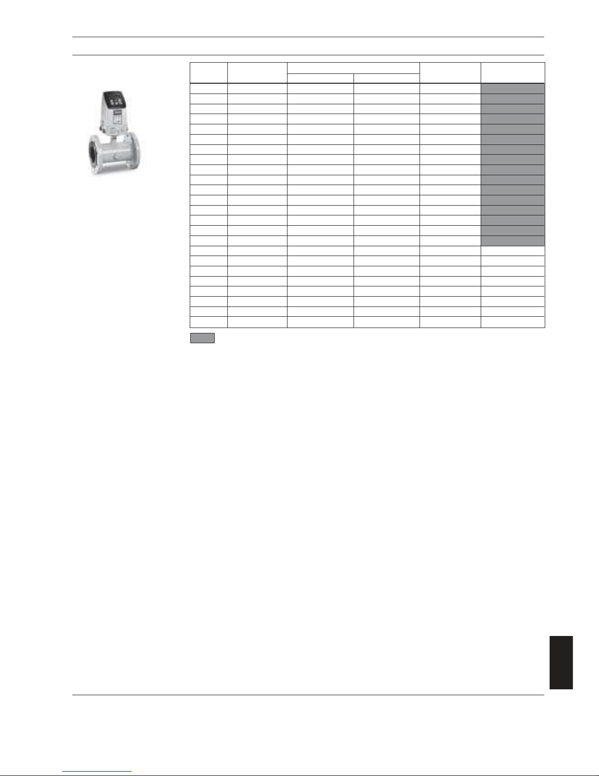
79
MAGFLO
â
Ordering
10. Ordering
10.5
Sensor MAG 5100 W
Size Facto ry Q
max.
GPM Flange
inc hes set GPM
Min. Max. type Code No.
1 25 1.9 77.8 ANSI 150 082Z8501
1½ 60 5.3 198.1 ANSI 150 082Z8503
2 100 7.0 277.4 ANSI 150 082Z8505
2½ 160 11.0 440.3 ANSI 150 082Z8507
3 250 17.6 704.5 ANSI 150 082Z8509
4 400 27.7 1,100.7 ANSI 150 082Z8511
5 600 44.0 1,761.1 ANSI 150 082Z8513
6 900 70.4 2,773.8 ANSI 150 082Z8515
8 1,500 110.1 4,402.8 ANSI 150 082Z8518
10 2,500 176.1 7,044.5 ANSI 150 082Z8521
12 3,500 277.4 11,007.1 ANSI 150 082Z8524
14 4,500 381.3 15,247.0 ANSI 150 082Z8527
16 6,000 498.0 19.914.0 ANSI 150 082Z8530
18 7,500 630.5 25,206.2 ANSI 150 082Z8533
20 9,500 778.4 31,119.2 ANSI 150 082Z8536
24 13,500 1,120.5 44,812.0 ANSI 150 082Z8539
28 18,500 1,525.1 60.996.9 AWWA 082Z8542
30 21,000 1,751.0 70,022.7 AWWA 082Z8543
32 24,000 1,991.8 79.669.3 AWWA 082Z8546
36 30,000 2,522.8 100,833.7 AWWA 082Z8549
40 37,000 3,112.8 124,485.7 AWWA 082Z8552
42 37,000 3,112.8 124,485.7 AWWA 082Z8553
44 45,000 3,765.7 150,625.3 AWWA 082Z8554
48 53,000 4,482.1 179,261,4 AWWA 082Z8557
Stock item
Page 80

80
MAGFLO
â
Ordering
10. Ordering
Description Version Enclosure Code No. Symbol
Signal converter MAG 5000 Blind for 11-30 V d.c./ NEMA 4X, fibre-
integral mount and wall mounting 11-24 V a.c. glass reinforced 083F5006
polyamide
115/230 V a.c. NEMA 4X, fibre-
50/60 Hz glass reinforced 083F5005
polyamide
Signal converter MAG 5000 for 11-30 V d.c./ NEMA 4X, fibre-
integral mount and wall mounting 11-24 V a.c. glass reinforced 083F5002
polyamide
115/230 V a.c. NEMA 4X, fibre-
50/60 Hz glass reinforced 083F5001
polyamide
115/230 V a.c. NEMA 4X, fibre-
50/60 Hz glass reinforced 083F5011
HART
â
polyamide
10.6
Signal converter
Integral mount polyamide
Description Version Enclosure Code No. Symbol
Signal converter MAG 6000 Blind for 11-30 V d.c./ NEMA 4X, fibre-
integral mount and wall mounting 11-24 V a.c. glass reinforced 083F5008
polyamide
115/230 V a.c. NEMA 4X, fibre-
50/60 Hz glass reinforced 083F5007
polyamide
Signal converter MAG 6000 for 11-30 V d.c./ NEMA 4X, fibre-
integral mount and wall mounting 11-24 V a.c. glass reinforced 083F5004
polyamide
115/230 V a.c. NEMA 4X, fibre-
50/60 Hz glass reinforced 083F5003
polyamide
Description Version Enclosure Code No. Symbol
Signal converter MAG 6000 CT for 11-30 V d.c./ NEMA 4X, fibre-
integral mount and wall mounting 11-24 V a.c. glass reinforced 083F5010
polyamide
115/230 V a.c. NEMA 4X, fibre-
50/60 Hz glass reinforced 083F5009
polyamide
Accessories
MAG 5000 and MAG 6000
Description Code No. Symbol
Wall mounting kit
Wall bracket, 4 Pg 13.5 cable glands 085U1001
Spare parts
Description Version Code No. Symbol
Connection plate 12-24 V 083F4113
115-230 V 083F4112
Add-on module
MAG 6000 only
Description Version Enclosure Code No. Symbol
Signal converter MAG 5000 CT for 11-30 V d.c./ IP 67, fibre-
compact and wall mounting 11-24 V a.c. glass reinforced 083F5046
polyamide
115/230 V a.c. IP 67, fibre-
50/60 Hz glass reinforced 083F5044
polyamide
Description Code No. Symbol
HA RT
â
085U0226
Profibus PA 085U0227
CANopen 085U0228
DeviceNet 085U0229
Profibus DP 085U0230
Page 81
81
MAGFLO
â
Ordering
Description Version Code No. Symbol
Signal converter MAG 5000 for rack 11-30 V d.c./ 083F5021
and panel mounting 11-24 V a.c.
115-230 V a.c. 083F5020
50/60 Hz
Signal converter MAG 6000 for rack 11-30 V d.c./ 083F5023
and panel mounting 11-24 V a.c.
115-230 V a.c. 083F5022
50/60 Hz
Signal converter MAG 6000
(" £ 12)
11-30 V d.c./
insert with safety barrier [EEx ia/ib] IIB 11-24 V a.c. 083F5041
Signal converter MAG 6000
(" £ 12)
115-230 V a.c.
insert with safety barrier [EEx ia/ib] IIB 50/60 Hz 083F5040
Wall boxes
(Without back plates and
without signal converter)
Description Code No. Symbol
NEMA 4X wall mounting enclosure for NEMA 2 rack mount inserts
083F5037
NEMA 4X wall mounting enclosure for NEMA 2 rack mount inserts
083F5038
Description Version Code No. Symbol
Cleaning unit for electrode cleaning 115-230 V a.c.
rack mount insert incl. back plate 50/60 Hz 083F5036
Cleaning unit for electrode cleaning 11-30 V d.c.
rack mount insert incl. back plate 11-24 V a.c. 083F5039
Panel mounting kit for rack mount insert
NEMA 4X enclosure in ABS plastic for panel-front mounting 083F5030
Panel mounting kit for rack mount insert
NEMA 4X enclosure in ABS plastic for panel-front mounting 083F5031
Back of panel mounting kit for rack mount insert
NEMA 2 enclosure in aluminium 083F5032
Back of panel mounting kit for rack mount insert
NEMA 2 enclosure in aluminium 083F5033
Front cover 083F4525
10. Ordering
Accessories
Description Version Code No. Symbol
MAG 6000 with NEMA 4X enclosure 115/230 V a.c.
50/60 Hz 083F5026
MAG 6000 rack mount insert and cleaning unit 115/230 V a.c.
complete mounted with 50/60 Hz 083F5029
NEMA 4X wall mounting enclosure
MAG 6000 rack mount insert and cleaning unit 11-30 V d.c.
complete mounted with 11-24 V a.c. 083F5047
NEMA 4X wall mounting enclosure
MAG 6000 rack mount insert and safety barrier 115/230 V a.c.
complete mounted with NEMA 4X
(sizes: 1/4'' to 12'')
50/60 Hz 083F5028
wall mounting enclosure,
[EEx ia/ib] IIB
Wall mounting units
complete
10.7
Signal converter rack
mount
Page 82

82
MAGFLO
â
Ordering
Description Code No. Symbol
Length
Cable 33 ft. 083F0121
Standard electrode and coil cable, 65 ft. 083F0210
3 x 18 gage PVC 130 ft. 083F0211
200 ft. 083F0212
330 ft. 083F0213
500 ft. 083F3052
650 ft. 083F3053
1650 ft. 083F3054
Cable 65 ft. 083F3095
Special electrode cable, 130 ft. 083F3094
double screened, PVC 200 ft. 083F3093
330 ft. 083F3092
500 ft. 083F3056
650 ft. 083F3057
1650 ft. 083F3058
Standard Pg 13.5 screwed cable entries
for above cables (nickel-plated brass) 2-off 083G3140
Standard Pg 13.5 screwed cable entries
for above cables in black polyamide (100°C) 2-off 083G0228
Sealing screws for sensor/signal converter 2-off 085U0221
Stainless steel (AISI 316) terminal box with lid 085U1000
Polyamide terminal box 085U1002
Complete incl. terminals incl. lid
Polyamide lid for terminal box 085U1003
2 kB SENSORPROMâ unit 085U1005
(Sensor serial No. must be specified when ordering)
Adapter for ½ NPT brass 083N4394
Adapter for ½ NPT stainless steel 083N4395
Adapter for ½ NPT polyamide 083N4396
10. Ordering
10.8
Accessories
Back plates
Description Enclosure Version Code No. Symbol
Signal converter rack mount 12-24 V 083F4117
115-230 V
Signal converter & ia, safety barrier rack mount 12-24 V 083F4118
115-230 V
Signal converter & ia/ib, safety barrier rack mount 12-24 V 083F4119
115-230 V
Signal converter & cleaning unit rack mount 12-24 V 083F4123
115-230 V
Signal converter Wall 12-24 V 083F4121
unit 115-230 V
Signal converter & ia, safety barrier Wall 12-24 V 083F4122
unit 115-230 V
Signal converter & ia/ib, safety barrier Wall 12-24 V 083F4120
unit 115-230 V
Signal converter & cleaning unit Wall 12-24 V 083F4124
unit 115-230 V
Page 83

MAGFLO
â
83
10. Ordering
10.9
Calibration
Initial calibration
Description
Standard calibration
Each sensor calibrated twice at two
calibration points
Included in sensor scope of delivery
Matched pair
Sensor and signal converter calibrated
together with standard calibration
Customer specified matched pair
Sensor with signal converter calibrated
in max. 10 customer specified points
Accredited Danfoss matched pairs
Calibrations acc. to EN 45001
Sealing and labeling instruction must follow
the order
- PTB cold water
- PTB other media than water
- OIML R75 hot water
- OIML R117 other media than water
- OIML R117 cold water
Accredited Delft matched pair
Calibration acc. to EN 45001
Sealing and labeling instruction as above
Wittness inspection
Any of above mentioned calibrations
Re-calibration
Description Code No. Code No. Code No. Code No.
1
/4" - 2 1/2" 3" - 6" 8" - 20" 24" - 48"
Matched pair
Sensor and signal converter calibrated 085F7302 085F7303 085F7304 085F7305
together with standard calibration
Customer specified matched pair
Sensor with signal converter calibrated 085F7377 085F7378 085F7379 085F7380
in max. 10 customer specified points
Accredited Danfoss matched pairs
Calibrations acc. to EN 45001
Sealing and labeling instruction must
follow the order
- PTB cold water 085F7387 085F7388 085F7389 085F7390
- PTB other media than water
- OIML R75 hot water
- OIML R117 other media than water
- OIML R117 cold water
Accredited Delft matched pair
Calibration acc. to EN 45001 N/A 085F7393 085F7394 085F7395
Sealing and labeling instruction as above
Add-on
Code No.: On application form to be filled
in and sent to FD-GB
Ordering
Page 84

ã Danfoss A/S (FD-SW/JH&MK/SSS/VR I) 11/2002 P70
DKFD.PS.027.W3.22
521H0879
The Danfoss A/S, Flow Division range contains:
MAGFLOâ electromagnetic flowmeters
MAGFLOâ flowmeters are used for all electrically conductive
liquids.
A wide range is offered for:
· The water treatment sector – enclosures are NEMA 4X/6 as
standar d.
· The chemical industry – Ex-approved and other versions
available.
· The food industry – stainless steel and other versions
available.
SONOFLOâ ultrasonic flowmeters
SONOFLOâ flowmeters measure flow in full pipes.
SONOFLOâ flowmeters measure media in liquid form, irrespective of electrical conductivity.
The range includes a one- to four-track flowmeter, SONO 3000.
The meter is also available in a integral mount Ex-version.
SONOFLOâ flowmeters can also be installed on existing pipes,
providing low cost installations, especially where large pipes are
concerned .
MASSFLOâ mass flowmeters
MASSFLOâ flowmeters measure flow direct in kg/h. In addition,
MASSFLOâ flowmeters measure:
· Densi ty
· Temperature
· Sugar concentration i.e. °Brix
MASSFLOâ flowmeters are available in stainless steel,
Hastelloy and with integrated heating.
MASSFLOâ flowmeters can be obtained in an intrinsically safe
version for explosive areas.
MASSFLOâ, MAGFLOâ, SONOFLOâ, SONOCALâ and SENSORPROMâ are registered Danfoss trademarks.
 Loading...