

Page 1
Technical Information
Axial Piston Pumps
Series 40 M46
powersolutions.danfoss.com
Page 2
Technical Information
Series 40 M46 Pumps
Revision history Table of revisions
Date Changed Rev
March 2017 Minor updates - FNR Control options 0209
October 2016 Minor updates 0208
May 2015 more corrections to tandem pumps model code BG
March 2015 correction to tandem pumps model code BF
January 2015 minor edits BE
January 2015 added port callouts - HC EDC drawings BD
November 2014 corrections to shaft options BC
July 2014 Edits to HC EDC Schematic BB
April 2014 Danfoss layout BA
2 | © Danfoss | March 2017 L1001029 | BC00000176en-US0209
Page 3

Technical Information
Series 40 M46 Pumps
Contents
Specifications
General Information
Features and Options
Operating Parameters
System Design Parameters
Model Code - Single Pumps
Model Code - Tandem Pumps
Options
Design Specifications......................................................................................................................................................................5
Technical Specifications.................................................................................................................................................................5
Operating Parameters.....................................................................................................................................................................5
Options.................................................................................................................................................................................................6
Fluid specifications.......................................................................................................................................................................... 6
M46 Pumps.........................................................................................................................................................................................7
M46 Variable Pumps........................................................................................................................................................................7
System Circuit Diagram..................................................................................................................................................................8
Schematic Diagram..........................................................................................................................................................................8
Features................................................................................................................................................................................................9
Options.................................................................................................................................................................................................9
Fluids.................................................................................................................................................................................................. 10
Viscosity........................................................................................................................................................................................10
Temperature...............................................................................................................................................................................10
Charge Pressure..............................................................................................................................................................................10
Control Pressure............................................................................................................................................................................. 10
Case Pressure...................................................................................................................................................................................11
System Pressure..............................................................................................................................................................................11
Speed Ratings..................................................................................................................................................................................11
Inlet Pressure................................................................................................................................................................................... 12
Sizing Equations............................................................................................................................................................................. 13
Filtration............................................................................................................................................................................................ 13
Suction Filtration.......................................................................................................................................................................14
Charge Pressure Filtration..................................................................................................................................................... 14
Redundant Braking System Requirement.............................................................................................................................15
Loop Flushing..................................................................................................................................................................................15
Reservoir............................................................................................................................................................................................15
Case Drain Usage for Tandem Pumps.................................................................................................................................... 15
Bearing Life and External Shaft Loading................................................................................................................................16
Hydraulic Unit Life......................................................................................................................................................................... 17
Mounting Flange Loads...............................................................................................................................................................17
Shaft Torques...................................................................................................................................................................................19
Shaft selection........................................................................................................................................................................... 19
Shaft torque and spline lubrication................................................................................................................................... 19
Shaft torque for tapered shafts............................................................................................................................................19
Single Pumps...................................................................................................................................................................................20
Tandem Pumps...............................................................................................................................................................................24
Shaft options....................................................................................................................................................................................28
Single pumps............................................................................................................................................................................. 28
Tandem pumps......................................................................................................................................................................... 30
Charge Pump...................................................................................................................................................................................31
Charge Pump Output Flow...................................................................................................................................................32
Charge Pump Power Requirements.................................................................................................................................. 32
Charge Relief Valve........................................................................................................................................................................32
High Pressure Relief Valve (HPRV) and Charge Check......................................................................................................33
Bypass Function..............................................................................................................................................................................34
Displacement Limiters................................................................................................................................................................. 34
©
Danfoss | March 2017 L1001029 | BC00000176en-US0209 | 3
Page 4

Technical Information
Series 40 M46 Pumps
Contents
Auxiliary Mounting Pads and Auxiliary Pumps................................................................................................................... 35
Manual Displacement Control (MDC) - Options AB, AC, AK, AW, and GB..................................................................36
Hydraulic Displacement - Options BA, BB and BC..............................................................................................................38
Electrical Displacement Control- Options CE, CG, CM, and CN..................................................................................... 41
High Current Electric Displacement Control - Options HA (12Vdc) and HB (24Vdc).............................................44
Response times..........................................................................................................................................................................46
Manual OverRide (MOR).............................................................................................................................................................. 46
Three-position Electrical Control - Options DA and DB................................................................................................... 47
Port Locations
Single Pump.....................................................................................................................................................................................50
Tandem Pump.................................................................................................................................................................................51
Installation Drawings - Single Pump Dimensions
Auxiliary Mounting Flanges....................................................................................................................................................... 52
Pump, filtration/charge pump options, MDC, displacement limiter...........................................................................53
Installation Drawings - Tandem Pump Dimensions
Auxiliary mounting flange..........................................................................................................................................................54
Rear mounting boss......................................................................................................................................................................55
Pumps, filtration/charge pump options, MDC, displacement limiters.......................................................................56
Control Options - Installation Drawings
Control options, AC, AK............................................................................................................................................................... 57
Option GB......................................................................................................................................................................................... 57
Options AB, AW...............................................................................................................................................................................58
HC EDC Control...............................................................................................................................................................................59
Hydraulic displacement control (HDC).................................................................................................................................. 60
Option CE..........................................................................................................................................................................................61
Options CG, CN............................................................................................................................................................................... 61
Options DA, DB............................................................................................................................................................................... 62
Reference Literature
Literature...........................................................................................................................................................................................63
4 | © Danfoss | March 2017 L1001029 | BC00000176en-US0209
Page 5
Technical Information
Series 40 M46 Pumps
Specifications
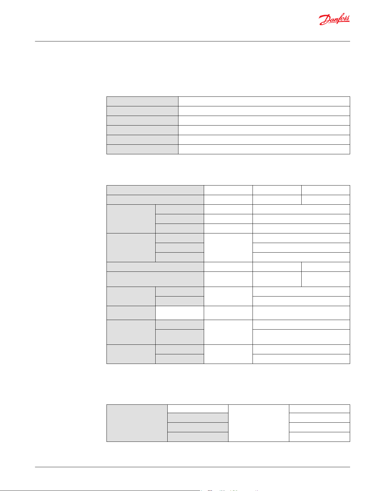
Design Specifications
Technical Specifications
Product line
Pump type
Direction rotation
Installation position
Filtration configuration
Other system requirements
Model
Displacement
Shaft Speed Minimum
Rated
Maximum
System Pressure Maximum working*
Maximum
Minimum low loop
Weight (MDC without aux pad)
Mass moment of inertia of the rotating
components
Charge Pressure Minimum
Maximum
Control Pressure
Case Pressure Continuous
Inlet Pressure Rated
Minimum @ corner
power
Maximum (cold
start)
Minimum
Series 40 Pumps
In-line, axial piston, variable, positive displacement pumps
Clockwise (CW) or counterclockwise (CCW) available
Discretionary, the housing must be filled with hydraulic fluid
Suction or charge pressure filtration
Independent braking system, suitable reservoir and heat exchanger
Unit M46 Single Pump M46 Tandem Pump
cm3/rev [in3/rev] 45.9 [2.80] 45.9 x 2 [2.80 x 2]
min-1 (rpm)
min-1 (rpm) 4000
min-1 (rpm) 4100
bar [psi] 345 [5000]
385 [5585]
10 [145]
kg [lb] 33 [73] 59 [131]
kg ·m2 [slug·ft2] 0.0050 [0.0037] 0.0100 [0.0073]
bar [psi] 6 [87]
31 [450]
bar [psi] 21.5 [312]
bar [psi] 1.7 [25]
5.2 [75]
bar absolute [inches
of Mercury vacuum]
0.8 [6]
6 [9.2 Maximum]
* Operation above maximum working pressure is permissible with Danfoss application approval.
Operating Parameters
Fluid Viscosity
©
Danfoss | March 2017 L1001029 | BC00000176en-US0209 | 5
Minimum mm2/s (cSt) [SUS] 7 [49]
Continuous
Maximum (cold start)
Intermittent
1
12-16 [70-278]
1600 [7500]
6 [46]
Page 6
Technical Information
Series 40 M46 Pumps
Specifications
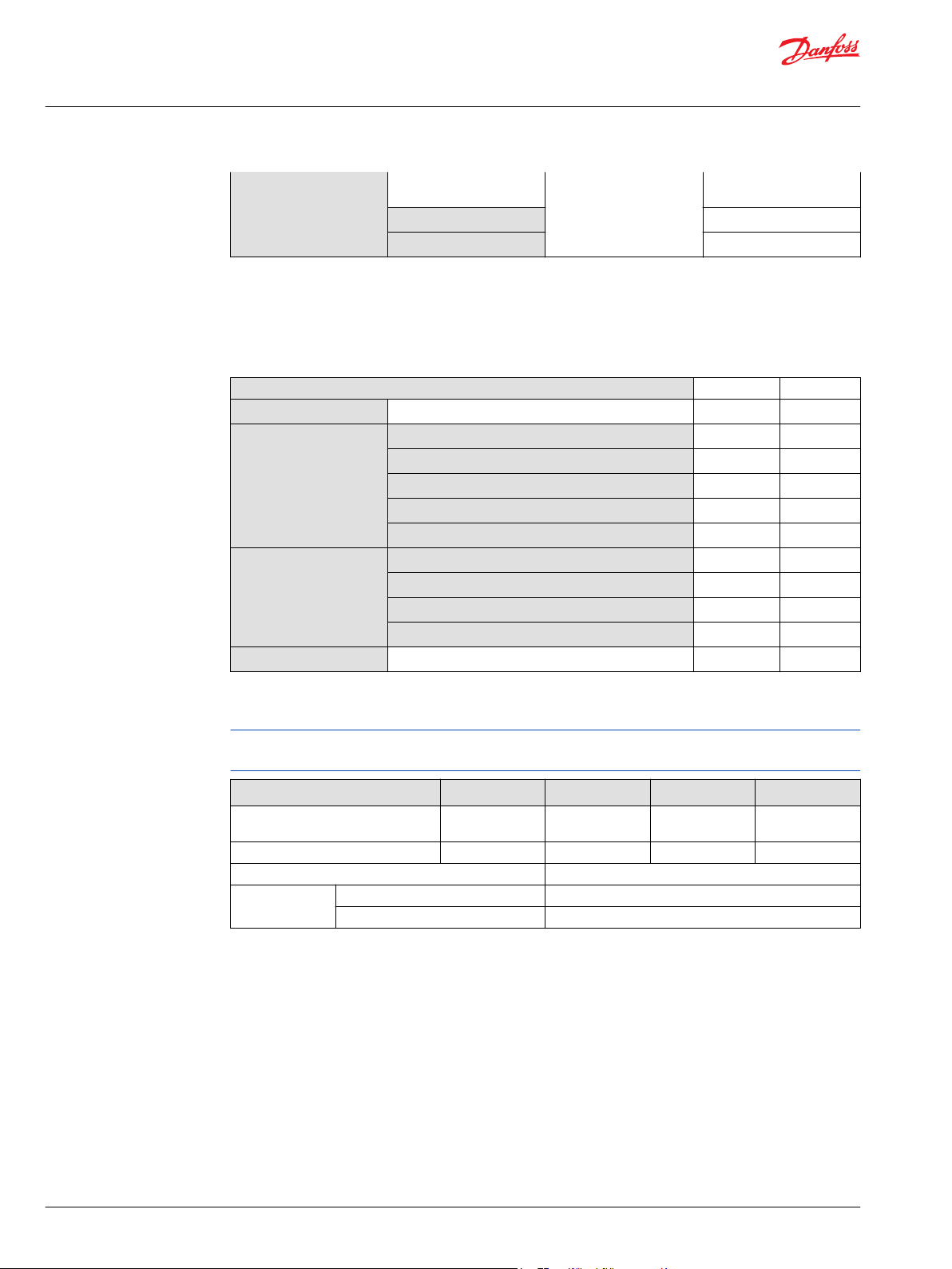
Options
Fluid Temperature
(1) Intermittent equals a short period of time at less than one minute per incident and not exceeding two percent of
duty cycle based on load life.
Mounting Flange
Input Shaft Ø 25.4 mm [1.000 in] straight keyed
Auxillary Mounting
Flange
Main Port Configuration
Minimum (intermittent cold
start)
Continuous
Maximum Intermittent
SAE - B X X
Ø 25.4 mm [1.000 in] 1:8 taper (SAE J501)
13-tooth, 16/32 pitch (ANSI B92.1 1970 - Class 5)
15-tooth, 16/32 pitch (ANSI B92.1 1970 - Class 5)
19-tooth, 16/32 pitch (ANSI B92.1 1970 - Class 5)
9-tooth internal spline, 16/32 pitch (SAE A)
11-tooth internal spline, 16/32 pitch (SAE A)
13-tooth internal spline, 16/32 pitch (SAE B)
15 - tooth internal spline, 16/32 pitch (SAE BB)
1-5/16 - 12 SAE A straight thread O-ring Ports (SAE J514) X X
degrees C [degrees F] - 40° C [- 40° F]
82.2° C [180° F]
1
104.4° C [220° F]
Single Tandem
X X
X X
X -
X X
- X
X X
X X
X X
- X
Fluid specifications
Ratings and data are based on operation with premium petroleum-based hydraulic fluids reftaining
oxidation, rust, and foam inhibitors.
Parameter Unit Minimum reftinuous Maximum
Viscosity mm /sec (cSt)
Temperature °C [°F] -40 [-40] 82 [180] 104 [220]
Cleanliness ISO 4406 Class 18/13 or better
Filtration
efficiency
suction filtration β
charge filtration β
[SUS]
7 [47] 12-60 [70-278] 1600 [7500]
=75 (β10≥1.5)
35-44
=75 (β10≥10)
15-20
6 | © Danfoss | March 2017 L1001029 | BC00000176en-US0209
Page 7
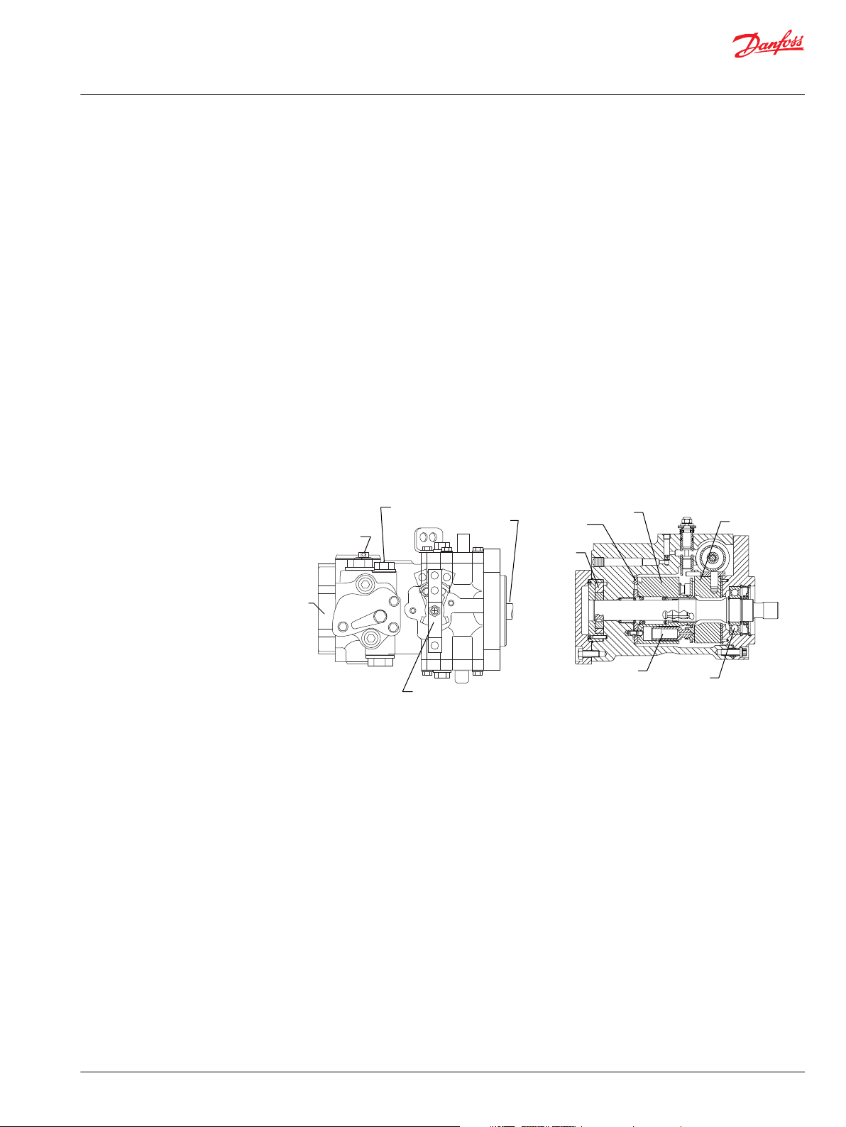
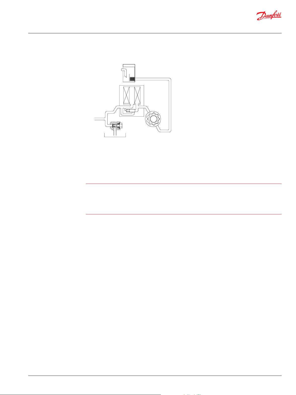
Input
shaft
Auxiliary
pad
Control
Charge check/
high pressure relief
valve
Charge relief
valve
Charge
pump
Valve plate
Piston
Cylinder
block
Cradle
swashplate
Ball
bearing
P100 585E
Technical Information
Series 40 M46 Pumps
General Information
M46 Pumps
M46 Variable Pumps
M46 pumps are designed for medium power applications with maximum loads of 345 bar [5000 psi].
These pumps can be combined with other products in a system to transfer and control hydraulic power.
M46 pumps provide an infinitely variable speed range between zero and maximum in both forward and
reverse modes of operation.
M46 pumps are compact, high power density units. All models use the parallel axial piston / slipper
concept in conjunction with a tiltable swashplate to vary the pump’s displacement. Reversing the angle
of the swashplate reverses the flow of fluid from the pump, reversing the direction of rotation of the
motor output.
M46 pumps may include an integral charge pump to provide system replenishing and cooling fluid flow,
as well as servo control fluid flow. M46 pumps feature a range of auxiliary mounting pads to accept
auxiliary hydraulic pumps for use in complementary hydraulic systems.
M46 pumps offer proportional controls with either manual, hydraulic, or electronic actuation. An electric
three-position control is also available.
©
Danfoss | March 2017 L1001029 | BC00000176en-US0209 | 7
Page 8
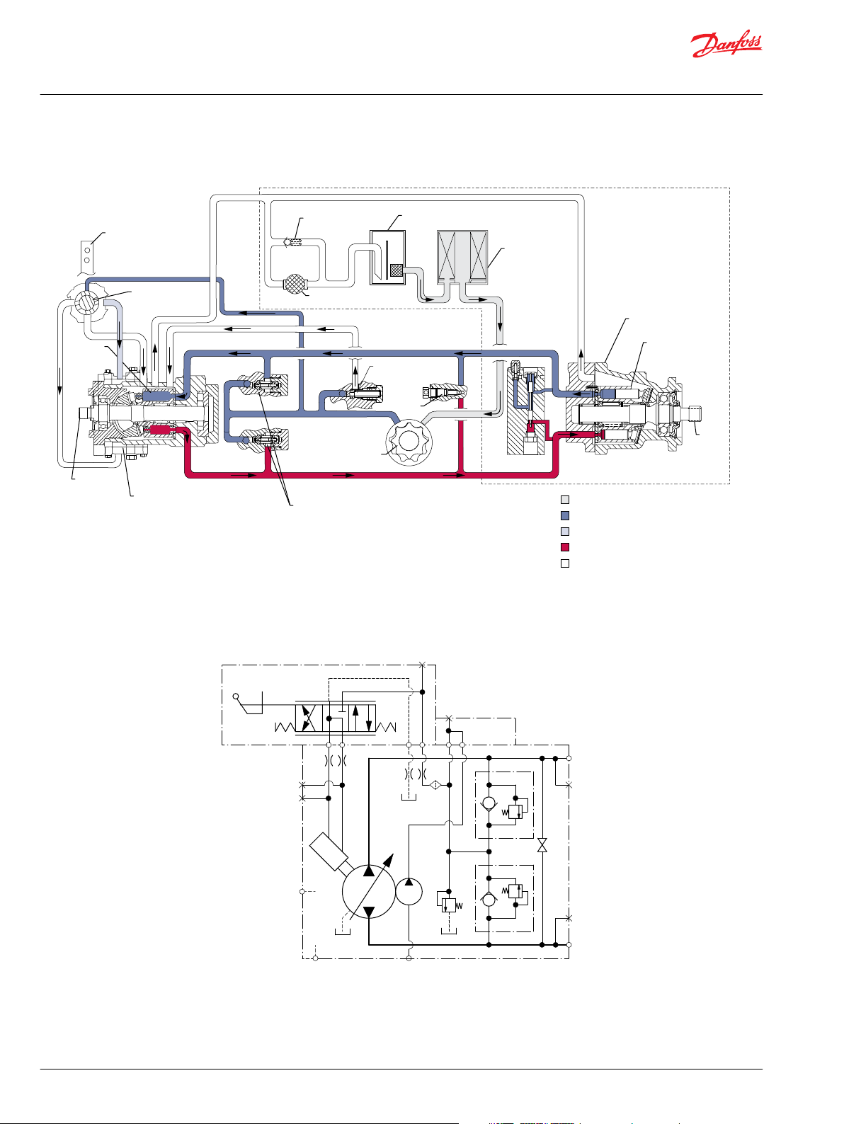
Input
shaft
Suction flow
Servo pressure
High pressure
Case flow
Charge pressure
Output
shaft
Cylinder
block
assembly
Filter
Charge
pump
Reservoir
Fixed displacement
motor
Cylinder
block
assembly
Heat
exchanger
Check valves
w/ high pressure
relief valve
Variable
displacement
pump
Heat exchanger
bypass
Charge relief
valve
Displacement
control
valve
Control
handle
Bypass
valve
Loop flushing
module
P100586
B
M2
M1
A
E
L1
L2
M5
M4
S
M3
B N A
P100587
Technical Information
Series 40 M46 Pumps
General Information
System Circuit Diagram
Schematic Diagram
8 | © Danfoss | March 2017 L1001029 | BC00000176en-US0209
Page 9

Technical Information
Series 40 M46 Pumps
Features and Options
Features
Options
•
Efficient Axial Piston Design
•
Compact, Lightweight Pumps
•
Worldwide Support
•
Low Noise
•
Single and Tandem Integrated Tandem Configurations
•
Manual, Hydraulic or Electric Control
High Pressure Relief Valve (HPRV) - A high pressure relief valve limits the system pressure to protect
the system from over-pressure.
Charge Relief Valve - The charge pressure relief valve regulates charge pressure.
Displacement Limiters - Optional displacement limiters allow maximum displacement adjustment to
allow for fine tuning of the propel system.
Auxiliary Mounting Pads - Several auxiliary mounting pad options allow for adding a second pump.
Control Options - Control options include manual displacement control (MDC), hydraulic displacement
control (HDC), electric displacement control (EDC), and threeposition electric displacement control (FNR).
Input Shafts - Straight keyed, tapered keyed, and several splined shaft options are available.
©
Danfoss | March 2017 L1001029 | BC00000176en-US0209 | 9
Page 10

Technical Information
Series 40 M46 Pumps
Operating Parameters
Fluids
Ratings and performance data are based on operating with premium hydraulic fluids containing
oxidation, rust, and foam inhibitors. These include premium turbine oils, API CD engine oils per SAE J183,
M2C33F or G automatic transmission fluids (ATF), Dexron II (ATF) meeting Allison C-3 or Caterpillar T0‑2
requirements, and certain specialty agricultural tractor fluids. For more information on hydraulic fluid
selection, see Danfoss publications: Hydraulic Fluids and Lubricants, Technical Information, 520L0463 and,
Experience with Biodegradable Hydraulic Fluids, Technical Information,520L465.
Viscosity
For maximum efficiency and bearing life, ensure the fluid viscosity remains in the recommended range.
The minimum viscosity should be encountered only during brief occasions.
Maximum temperature is based on material properties. Measure maximum temperature at the hottest
point in the system. This is usually the case drain. The maximum viscosity should be encountered only at
cold start, and is merely a reflection of a viscosity condition supporting an engine start, at idle. Normal
vehicle operation and performance should not occur until the fluid viscosity improves with increrased
temperature. For more information on viscosity, see Danfoss publication, Hydraulic Fluids and Lubricants,
Technical Information 520L0463.
Charge Pressure
Temperature
Maintain fluid temperature within the limits shown in the table. Minimum temperature relates to the
physical properties of the component materials. Cold oil will not affect the durability of the pump
components. However, it may affect the ability of the pump to transmit power.
Maximum temperature is based on material properties. Measure maximum temperature at the hottest
point in the system. This is usually the case drain.
Ensure fluid temperature and viscosity limits are concurrently satisfied.
An internal charge relief valve regulates charge pressure. Charge pressure supplies the control with
pressure to operate the swashplate and to maintain a minimum pressure in the low side of the
transmission loop.
The charge pressure setting listed in the order code is the set pressure of the charge relief valve with the
pump in neutral, operating at 1800 min-1 [rpm], and with a fluid viscosity of 32 mm2/s [150 SUS]. Pumps
configured with no charge pump (external charge supply) are set with a charge flow of 19 l/min [5 US gal/
min] (single pumps), 38 l/ min [10 US gal/min] (tandem pumps), and a fluid viscosity of 32 mm2/s [150
SUS].
The charge pressure setting is referenced to case pressure. Charge pressure is the differential pressure
above case pressure.
Minimum charge pressure is the lowest pressure allowed in order to maintain a safe working condition
in the low side of the loop. Minimum control pressure requirements are a function of speed, pressure,
and swashplate angle, and may be higher than the minimum charge pressure shown in the Specifications
section.
Maximum charge pressure is the highest charge pressure allowed by the charge relief adjustment, and
which provides normal component life. Elevated charge pressure can be used as a secondary means to
reduce the swashplate response time.
Control Pressure
Control pressure is the pressure in the servo system needed to position and hold the pump on stroke.
Servo pressure depends on system pressure and speed.
10 | © Danfoss | March 2017 L1001029 | BC00000176en-US0209
Page 11

C
Technical Information
Series 40 M46 Pumps
Operating Parameters
Case Pressure
System Pressure
At minimum control pressure, the pump will run at reduced stroke depending on speed and pressure.
Minimum control pressure at corner power holds the pump on full stroke at maximum speed and
maximum pressure.
Maximum control pressure is the highest pressure typically given by the charge pressure setting.
Under normal operating conditions, do not exceed rated case pressure. During cold start, keep case
pressure below maximum intermittent case pressure.
CAUTION
Operating outside of charge and case pressure limits will damage the pump. To minimize this risk, use full
size inlet and case drain plumbing, and limit line lengths.
System pressure is the differential pressure between high pressure system ports. It is the dominant
operating variable affecting hydraulic unit life. High system pressure, which results from high load,
reduces expected life. Hydraulic unit life depends on the speed and normal operating, or weighted
average, pressure that can only be determined from a duty cycle analysis.
Application pressure is the high pressure relief or pressure limiter setting normally defined within the
order code of the pump. This is the applied system pressure at which the driveline generates the
maximum calculated pull or torque in the application.
Maximum Working pressure is the highest recommended application pressure. Maximum working
pressure is not intended to be a continuous pressure. Propel systems with application pressures at, or
below, this pressure should yield satisfactory unit life given proper component sizing.
Maximum pressure is the highest allowable application pressure under any circumstance. Application
pressures above maximum working pressure will only be considered with duty cycle analysis and factory
approval.
Minimum low loop pressure must be maintained under all operating conditions to avoid cavitation.
All pressure limits are differential pressures referenced to low loop (charge) pressure. Subtract low loop
pressure from gauge readings to compute the differential.
Speed Ratings
Minimum speed is the lowest input speed recommended during engine idle condition. Operating below
minimum speed limits the pump’s ability to maintain adequate flow for lubrication and power
transmission.
Rated speed is the highest input speed recommended at full power condition. Operating at or below
this speed should yield satisfactory product life.
Maximum speed is the highest operating speed permitted. Exceeding maximum speed reduces product
life and can cause loss of hydrostatic power and braking capacity. Never exceed the maximum speed
limit under any operating conditions.
Operating conditions between rated speed and maximum speed should be restricted to less than full
power and to limited periods of time. For most drive systems, maximum unit speed occurs during
downhill braking or negative power conditions.
For more information consult Pressure and Speed Limits BLN-9884, when determining speed limits for a
particular application.
©
Danfoss | March 2017 L1001029 | BC00000176en-US0209 | 11
Page 12

W
Technical Information
Series 40 M46 Pumps
Operating Parameters
Inlet Pressure
During hydraulic braking and downhill conditions, the prime mover must be capable of providing
sufficient braking torque in order to avoid pump over speed. This is especially important to consider for
turbocharged and Tier 4 engines.
Warning
Unintended vehicle or machine movement hazard.
The loss of hydrostatic drive line power, in any mode of operation (forward, neutral, or reverse) may cause
the system to lose hydrostatic braking capacity. You must provide a braking system, redundant to the
hydrostatic transmission, sufficient to stop and hold the vehicle or machine in the event of hydrostatic
drive power loss.
Achieving acceptable pump life and performance requires proper charge pump inlet design. A
continuous inlet pressure of not less than 0.8 bar absolute (not more than 6.3 inches Hg vacuum) is
recommended. Normal pressure less than the minimum inlet pressure of 0.7 bar absolute (greater than
9.2 inches Hg vacuum) indicates inadequate inlet design or a restricted filter. Pressures less than 0.7 bar
absolute (greater than 9.2 inches Hg vacuum) during cold start are likely, but should improve quickly as
the fluid warms.
12 | © Danfoss | March 2017 L1001029 | BC00000176en-US0209
Page 13
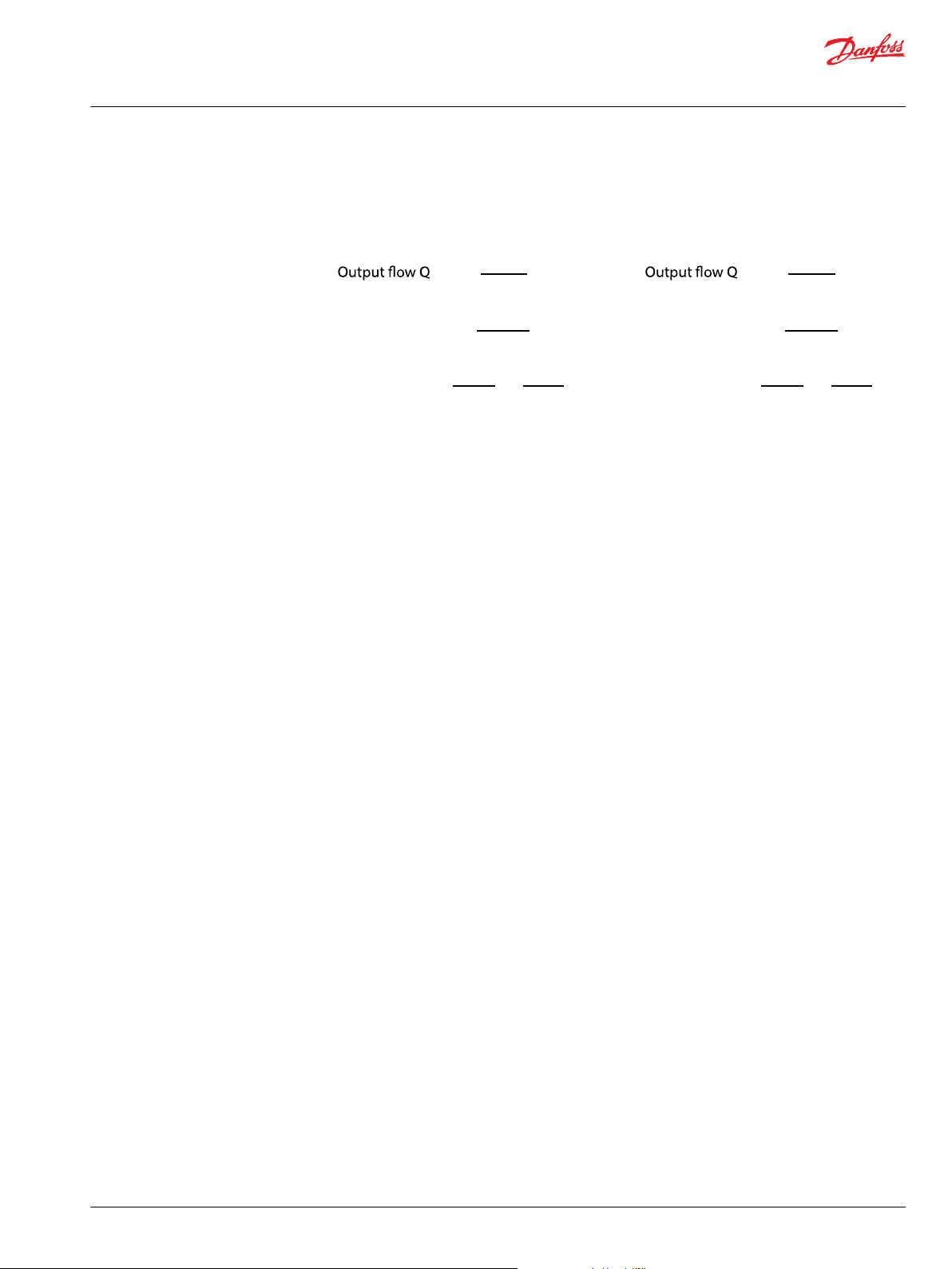
Based on SI units
= (l/min)
Input torque M = (N•m)
Input power P = = (kW )
Based on US units
= (US gal/min)
Input torque M = (lbf•in)
Input power P = = (hp)
Vg • n • η
v
1000
Vg • ∆p
20 • π • η
m
Q • ∆p
600 • η
t
M • n • π
30 000
Vg • n • η
v
231
Vg • ∆p
2 • π • η
m
Q • ∆p
1714 • η
t
M • n • π
198 000
Flow
Torque
Power
Technical Information
Series 40 M46 Pumps
System Design Parameters
Sizing Equations
Use these equations to help choose the right pump size and displacement for your application.
Variables
SI units [US units]
Vg = Displacement per revolution cm3/rev [in3/rev]
pO = Outlet pressure bar [psi]
pi = Inlet pressure bar [psi]
∆p = pO - pi (system pressure) bar [psi]
n = Speed min-1 (rpm)
ηv = Volumetric efficiency
ηm = Mechanical efficiency
ηt = Overall efficiency (ηv • ηm)
Filtration
Ensure fluid entering pump is free of contaminants to prevent damage (including premature wear) to the
system. M46 pumps require system filtration capable of maintaining fluid cleanliness at ISO 4406-1999
class 22/18/13 or better.
Consider these factors when selecting a system filter:
•
Cleanliness specifications
•
Contaminant ingression rates
•
Flow capacity
•
Desired maintenance interval
Locate filter either on the inlet (suction filtration) or discharge (charge pressure filtration) side of the
charge pump.
Filter efficiency can be measured with a Beta ratio¹ (βX). For simple suction-filtered closed circuit
transmissions and open circuit transmissions with return line filtration, a filter with a β-ratio within the
range of β35-45 = 75 (β10 ≥ 2) or better has been found to be satisfactory. Systems with multiple
cylinders that are feed from a single reservoir require a more efficient filter. This also applies to systems
with gears or clutches using a common reservoir.
For high volume systems, use a charge pressure or return filtration system with a filter β-ratio in the range
of β15-20 = 75 (β10 ≥ 10) or better.
Because each system is unique, only a thorough testing and evaluation program can fully validate the
filtration system. Please see Design Guidelines for Hydraulic Fluid Cleanliness Technical Information
520L0467 for more information.
©
Danfoss | March 2017 L1001029 | BC00000176en-US0209 | 13
Page 14
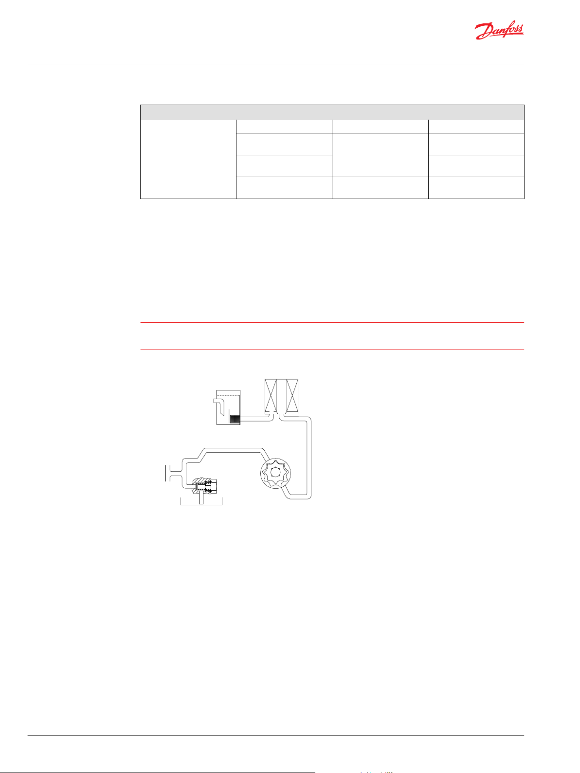
C
Reservoir
Filter
Charge
pump
Charge relief
valve
To pump case
To low pressure
side of loop
and servo control
Strainer
P100588
Technical Information
Series 40 M46 Pumps
System Design Parameters
Cleanliness level and βx-ratio
Filtration (recommended
minimum)
1
Filter βx-ratio is a measure of filter efficiency defined by ISO 4572. It is defined as the ratio of the number
Cleanliness per ISO 4406 22/18/13
Efficiency (charge pressure
filtration)
Efficiency (suction and
return line filtration)
Recommended inlet screen
mesh size
β-ratio β
μm 100 – 125
= 75 (β10 ≥ 10)
15-20
β
= 75 (β10 ≥ 2)
35-45
of particles greater than a given diameter (“x” in microns) upstream of the filter to the number of these
particles downstream of the filter.
Suction Filtration
The filter is located between the reservoir and the charge pump inlet, as shown in the accompanying
illustration.
CAUTION
Operating outside of charge and case pressure limits will damage the pump. To minimize this risk, use full
size inlet and case drain plumbing, and limit line lengths.
Suction filtration
Charge Pressure Filtration
The filter is mounted remotely after the charge pump outlet, as shown in the accompanying illustration.
For charge pressure filtration, use a filter that is rated to at least 34.5 bar [500 psi] pressure. Use a 100 -
125 μm screen in the reservoir or charge inlet line.
A bypass valve is necessary to prevent filter damage and to avoid contaminants from being forced
through the filter by high pressure. In the event of high pressure drop associated with a blocked filter or
cold start-up conditions, fluid will bypass the filter. Avoid working with an open bypass for an extended
period. We recommend a visual or electrical bypass indicator. Proper filter maintenance is mandatory.
14 | © Danfoss | March 2017 L1001029 | BC00000176en-US0209
Page 15
Reservoir
Filter
with bypass
Charge
pump
Charge relief
valve
To pump case
To Low Pressure
side of loop
and servo control
Strainer
P106102
W
Technical Information
Series 40 M46 Pumps
System Design Parameters
Charge filtration
Redundant Braking System Requirement
Warning
Unintended vehicle or machine movement hazard
The loss of hydrostatic drive line power, in any mode of operation (forward, neutral, or reverse) may cause
the system to lose hydrostatic braking capacity. You must provide a braking system, redundant to the
hydrostatic transmission, sufficient to stop and hold the vehicle or machine in the event of hydrostatic
drive power loss.
Loop Flushing
Closed circuit systems may require loop flushing to meet temperature and cleanliness requirements. A
loop flushing valve removes hot fluid from the low pressure side of the system loop for additional cooling
and filtering. Ensure the charge pump provides adequate flow for loop flushing and the loop flushing
valve does not cause charge pressure to drop below recommended limits.
Reservoir
The reservoir provides clean fluid, dissipates heat, and removes entrained air from the hydraulic fluid. It
allows for fluid volume changes associated with fluid expansion and cylinder differential volumes.
Minimum reservoir capacity depends on the volume needed to perform these functions. Typically, a
capacity of one half the charge pump flow (per minute) is satisfactory for a closed reservoir. Open circuit
systems sharing a common reservoir require greater fluid capacity.
Locate the reservoir outlet (suction line) near the bottom, allowing clearance for settling foreign particles.
Use a 100 - 125 μm screen covering the outlet port.
Place the reservoir inlet (return lines) below the lowest expected fluid level, as far away from the outlet as
possible.
Use a baffle (or baffles) between the reservoir inlet and outlet ports to promote de-aeration and reduce
fluid surging.
Case Drain Usage for Tandem Pumps
©
Danfoss | March 2017 L1001029 | BC00000176en-US0209 | 15
The tandem housings are connected through the center section via a drilled hole. The charge relief valve
discharges oil into the front housing. In order to provide positive flow through both housings, use a case
Page 16

Technical Information
Series 40 M46 Pumps
System Design Parameters
drain in the rear housing. The front housing case drain ports should only be used if the pump is used as a
common drain manifold for the vehicle where external drain flow is brought into the rear housing and
discharged out the front.
Allowable case pressure limits must be satisfied.
Bearing Life and External Shaft Loading
Bearing life is a function of speed, system pressure, charge pressure, and swashplate angle, plus any
external side or thrust loads. Other life factors include oil type and viscosity. The influence of swashplate
angle includes displacement as well as direction. External loads are found in applications where the
pump is driven with side/thrust load (belt or gear) as well as in installations with misalignment and
improper concentricity between the pump and drive coupling.
In vehicle propel drives with no external shaft loads and where the system pressure and swashplate angle
are changing direction and magnitude regularly, the normal L20 bearing life (80% survival) will exceed
the hydraulic load-life of the unit.
In non propel drives such as vibratory drives, conveyor drives, or fan drives, the operating speed and
pressure are often nearly constant and the swashplate angle is predominantly at maximum. These drives
have a distinctive duty cycle compared to a propulsion drive. In these types of applications a bearing life
review is recommended.
M46 pumps are designed with bearings that can accept some external radial and thrust loads. When
external loads are present, the allowable radial shaft loads are a function of the load position relative to
the mounting flange, the load orientation relative to the internal loads, and the operating pressures of
the hydraulic unit. In applications where external shaft loads can not be avoided, the impact on bearing
life can be minimized by proper orientation of the load. Optimum pump orientation is a consideration of
the net loading on the shaft from the external load, the pump rotating group, and the charge pump load.
A high capacity (cylindrical roller) input shaft bearing is available for applications with high external shaft
loads. Contact your Danfoss representative.
In applications where the pump is operated such that nearly equal amounts of forward vs reverse
•
swashplate operation is experienced; bearing life can be optimized by orientating the external side
load to the 0 or 180 deg position (90 deg to rotating group load Fb). See drawing.
In applications where the pump is operated such that the swashplate is predominantly (>75%) on
•
one side of neutral (e.g. vibratory, conveyor, typical propel); bearing life can be optimized by
orientating the external side load generally opposite of the internal rotating group load, Fb. The
direction of the internal loading is a function of rotation and system port, which has flow out.
Avoid axial thrust loads in either direction.
•
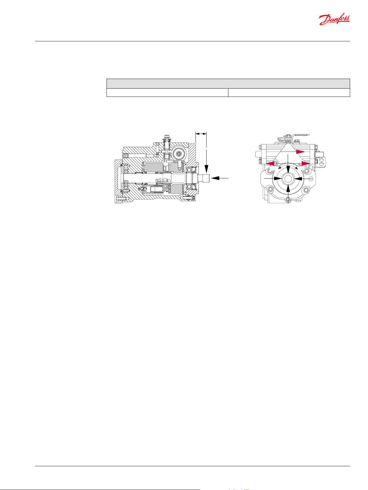
The maximum allowable radial loads (Re), based on the maximum external moment (Me) and the
distance (L) from the mounting flange to the load, may be determined from the tables below and the
cross section drawing.
The maximum allowable radial load is calculated as: Re = Me / L
Contact your Danfoss representative for an evaluation of unit bearing life if continuously applied external
radial loads are 25% or more of the maximum allowable, or if thrust loads are known to exist.
Shaft loading parameters
Re Maximum external radial load
Me Me Maximum external moment
L Distance from mounting flange to point of load
Fb Force of cylinder block
Te Thrust external load
Fcp Force of charge pump
16 | © Danfoss | March 2017 L1001029 | BC00000176en-US0209
Page 17
L
Re
Te
P100594
270
Re
0
Re
90
Re
180
Re
CW
CCW
F
cp
F
b
Technical Information
Series 40 M46 Pumps
System Design Parameters
Maximum external shaft moments
Standard Bearing
Me/N•m [in·lbf ] 186 [1650]
External radial shaft load
Hydraulic Unit Life
Mounting Flange Loads
Hydraulic unit life is defined as the fatigue life expectancy of the hydraulic components. It is a function of
speed and system pressure; however, system pressure is the dominant variable. High pressure, which
results from high load, reduces expected hydraulic unit life.
System component selection is based on determination of the application maximum loads and speeds.
Testing is recommended to secure duty cycle data in which to predict hydraulic unit life. Contact your
Danfoss representative for assistance in unit life determination. If duty cycle data is not available, normal
input power and maximum pump displacement can be used to determine an application pressure in
which to predict life.
M46 pumps will meet most application hydraulic unit life expectancies if applied within the parameters
specified in this manual and chosen considering the guidelines within Danfoss publication Selection of
Driveline Components BLN-9885. For more detailed information on hydraulic unit life, see Danfoss
publication Pressure and Speed Limits BLN-9884.
Shock load moment is the result of an instantaneous jolt to the system. Continuous load moments are
generated by the typical vibratory movement of the application. Avoid excessive loading of the
mounting flange such as adding tandem mounted auxiliary pumps and/or subjecting pumps to high
shock loads. Design pump applications to stay within the allowable shock load moment and allowable
continuous load moment.
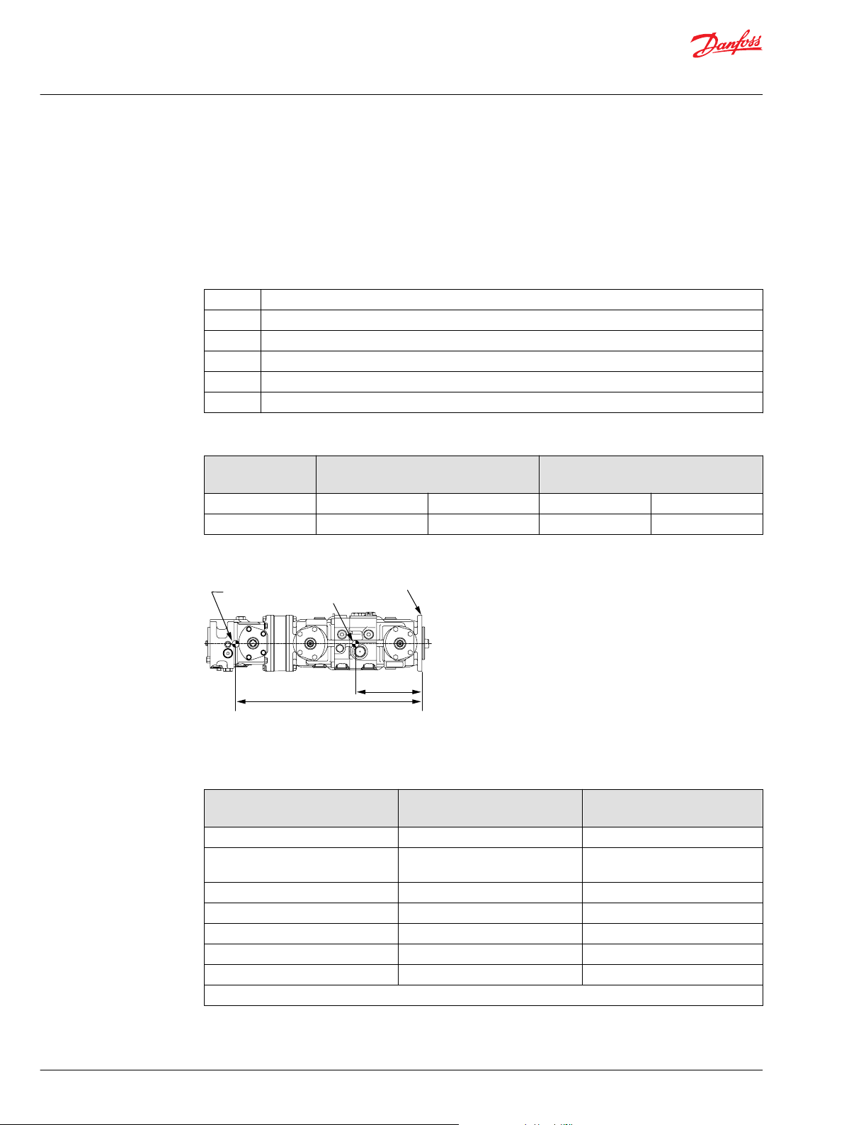
Use the following formulas to estimate overhung load moment for multiple pump mountings:
MS = GS (W1L1 + W2L2 + ... +WnLn)
MC = GC (W1L1 + W2L2 + ... +WnLn)
Refer to the Installation Drawings section to find pump length (L). Refer to the table Technical
Specifications in the Specifications section, to find pump weight (W). An exact measure of W will depend
on the pump’s features.
©
Danfoss | March 2017 L1001029 | BC00000176en-US0209 | 17
Page 18
Mounting
flange
CG
Pump 1
CG
Pump 2
L1
L2
P100 596E
Technical Information
Series 40 M46 Pumps
System Design Parameters
The tables below show allowable overhung load moment values. If system parameters exceed these
values add additional pump support.
Estimated maximum and continuous acceleration factors for some typical Series 40 applications are
shown. Applications which experience extreme resonant vibrations may require additional pump
support. Typical continuous (vibratory) values can vary significantly due to changes in engine and pump
configuration and mounting methods.
Overhung loading parameters
M
s
M
c
G
s
G
c
W
n
L
n
Shock load moment
Continuous load moment
Maximum shock acceleration (Gs)
Continuous (vibratory) acceleration (Gs)
Weight of nth pump
Distance from mounting flange to center of gravity of nth pump
Allowable overhung parameters
Frame size Continuous load moment (Mc) 107 cycles
N•m [in·lbf]
M46 PV 517 [4600] 832 [7400]
M46 PT 517 [4600] 754 [6700]
Shock load moment (Ms) 103 cycles
N•m [in·lbf]
Shaft loading parameters
The illustration shows a tandem plus a single pump.
G-factors for sample applications
Application Continuous (vibratory)
acceleration (Gc)
Skid steer loader 4 10
Trencher
(rubber tires)
Asphalt paver 2 6
Windrower 2 5
Aerial lift 1.5 4
Turf care vehicle 1.5 4
Vibratory roller 6 10
* Applications which experience extreme resonant vibrations require addition pump support.
3 8
Maximum (shock) acceleration
(Gs)
18 | © Danfoss | March 2017 L1001029 | BC00000176en-US0209
Page 19

Technical Information
Series 40 M46 Pumps
System Design Parameters
Shaft Torques
Shaft selection
Base shaft selection on a review of the maximum torque required by the application and the maximum
torque available from the prime mover. Application duty cycle and continuous torque rating of the prime
mover are the main variable to consider when selecting a shaft.
Shaft torque and spline lubrication
The rated torque is a measure of tooth wear and is the torque level at which a normal spline life of 1 x
107 shaft revolutions can be expected. The rated torque presumes a regularly maintained minimum level
of lubrication via a moly-disulfide grease in order to reduce the coefficient of friction and to restrict the
presence of oxygen at the spline interface. It is also assumed that the mating spline has a minimum
hardness of Rc 55 and full spline depth. The rated torque is proportional to the minimum active spline
length.
However, a spline running in oil-flooded environment provides superior oxygen restriction in addition to
contaminant flushing. The rated torque of a flooded spline can increase to that of the maximum
published rating. A flooded spline would be indicative of a pump driven by a pump drive or plugged into
an auxiliary pad of a pump.
Maximum torque ratings are based on torsional fatigue strength considering 1 x 10⁵ full load reversing
cycles.
Maintaining a spline engagement at least equal to the pitch diameter will also maximize spline life. Spline
engagements of less than ¾ pitch diameter are subject to high contact stress and spline fretting.
Shaft torque for tapered shafts
The rated torque is based on the contact pressure between the shaft and hub surfaces with poor contact
areas. With increased quality of the contact areas, the contact pressure between shaft and hub is
increased, allowing higher torque to be transmitted.
A key is intended as an installation aid only. Any torque carried by the key as a result of poor contact area
or mis-alignment will limit the torque carrying capability of the shaft significantly.
Maximum torque rating is based on an ideal contact area of 100% and the retaining nut properly
torqued. This allows for the highest contact pressure between the shaft and the mating hub.
©
Danfoss | March 2017 L1001029 | BC00000176en-US0209 | 19
Page 20
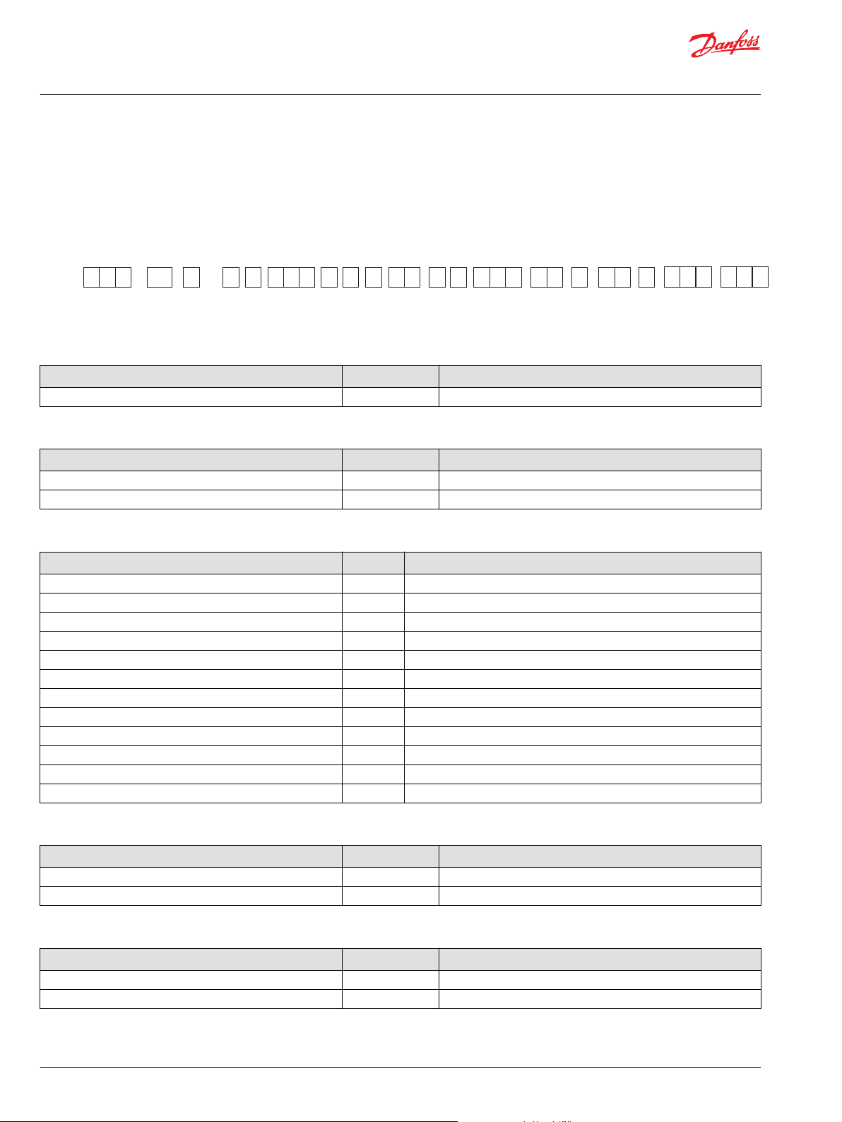
C D E F G H J L N
P
R
T Z
K
M
S
Product Frame
Type
MPV 046
C
Technical Information
Series 40 M46 Pumps
Model Code - Single Pumps
Single Pumps
C Swashplate
Description Code Remarks
Standard B
D - Seal Group
Description Code Remarks
Seal group for MDC A Must select an MDC control
Seal group for EDC/HDC/FNR B Must select an EDC/HDC/FNR control
E - Input Shaft/Auxiliary Spline
Description Code Remarks
13T 16/32 Spline / None A Requires S: None aux.. pad
13T 16/32 Spline / 9T 16/32 SplineR B Requires S: SAE-A aux.. pad
13T 16/32 Spline / 11T 16/32 Spline L Requires S: SAE-A aux.. pad
13T 16/32 Spline / 13T 16/32 Spline D Requires S: SAE-B aux.. pad
15T 16/32 Spline / None G Requires S: None aux.. pad
15T 16/32 Spline / 9T 16/32 Spline H Requires S: SAE-A aux.. pad
15T 16/32 Spline / 11T 16/32 Spline J Requires S: SAE-A aux.. pad
15T 16/32 Spline / 13T 16/32 Spline K Requires S: SAE-B aux.. pad
Tapered, 1 inch dia., 1.5 in/foot, square key/9T 16/32 Spline P Requires S: SAE-A aux.. pad. Includes key and nut
Tapered, 1 inch dia., 1.5 in/foot, square key/ 13T 16/32 Spline S Requires S: SAE-B aux.. pad. Includes key. Nut is customer supplied
Straight key, 1 inch diamater / None V Requires S: None aux.. pad. Includes key.
Straight key, 1 inch diameter / 9T 16/32 Spline W Requires S: SAE-A aux.. pad, includes key.
F - Rotation and valve plate
Description Code Remarks
CW, Quiet (Standard) S CP15; 3 deg. index. Requires charge pressure > 19.5 bar.
CCW, Quiet (Standard) T CP15; 3 deg. index. Requires charge pressure > 19.5 bar.
G - Charge pump
Description Code Remarks
None A Charge relief set at 19 l/min, external supply
13.9 cc [0.85 in./cu] B Charge relief set at 1800 rpm
20 | © Danfoss | March 2017 L1001029 | BC00000176en-US0209
Page 21

Technical Information
Series 40 M46 Pumps
Model Code - Single Pumps
H - Charge pressure
Description Code Remarks
19.5 bar B
21.5 bar J
25.0 bar S EDC/HDC controls calibrated at 20.7 bar charge
J - Filtration
Description Code Remarks
Suction, with charge pump AA Requires G: with charge pump
Remote pressure, with charge pump BA Requires G: with charge pump
Remote (external) pressure , without charge pump BC Requires G: no charge pump
Suction, with charge pump (HC EDC housing) HA requires G: with charge pump, N: with HC EDC
Remote pressure with charge pump(HC EDC housing) HB requires G: with charge pump, N: with HC EDC
Remote (external) pressure, without charge pump (HC EDC
housing)
HC requires G: no charge pump, N: with HC EDC
K - Displacement limiters
Description Code Remarks
Full displacement, 46 cc/rev [2.8 cu. in./rev] A
46 cc/rev [2.8 cu. in./rev] with adj. limiter, side #2 only,
centered side #2
V
L - Bypass valve
Description Code
Bypass valve A
M - System pressure protection, A and B ports
Port protection
Plug type Letter Port A Port B
Standard B Relief/Check Relief/Check
Second and Third Letter
M 140 bar
B 175 bar
C 100 bar
D 210 bar
E 230 bar
F 250 bar
G 280 bar
H 300 bar
R 325 bar
J 345 bar
Contact your Danfoss representative for configurations or pressures not shown.
©
Danfoss | March 2017 L1001029 | BC00000176en-US0209 | 21
Page 22

Technical Information
Series 40 M46 Pumps
Model Code - Single Pumps
N - Control type
Description Code Remarks
MDC handle with (2) 10 mm diameter holes, standard spring AB Recommend AW with metered spool
MDC with (3) 10 mm diameter holes, standard spring AC Recommend AK with metered spool
MDC with (3) 10 mm diameter holes, U shaped, standard
spring, metered spool
MDC handle with (2) 10 mm diameter holes, standard spring,
metered spool
MDC heavy duty handle with (4) 10 mm diameter holes, heavy
spring, metered spool
HDC 1.3-11.7 bar BA 19-170 psi
HDC 3.0-13.8 bar BB 44-200 psi
HDC 4.8-15.2 bar BC 70-220 psi
EDC dual coil, oil filled, Packard connector, 4-pin, 23-132 mA CE
EDC dual coil, oil filled, MS connector, 4-pin, 23-132 mA CG
EDC dual coil, oil filled, Deutsch connector, 4-pin, 23-132 mA CN
FNR 12 volt, DIN 43650 connector DA
FNR 24 volt, DIN 43650 connector DB
EDC, high current, 12 volt, Deutsch connector, 2-pin HA
EDC, high current, 24 volt, Deutsch connector, 2-pin HB
AK
AW
GB P; handle position to be B
P - Handle position
Description Code Remarks
Not applicable (EDC, HDC, FNR) A
Both, up and down B N: MDC to include heavy duty 4-hole handle. Handle is symmetric
Down (MDC) D 2, or 3 hole handles only. Handle oriented away from suction port.
Up (MDC) U 2, or 3 hole handles only. Handle oriented towards from suction
over spool
port.
R - Control orifice (contact factory for orifice options not shown)
MDC
Supply Drain (Supply and drain
F - None F - None
A - 0.031 inch A - 0.031 inch
B - 0.036 inch B - 0.036 inch
C - 0.041 inch D - 0.041 inch
D - 0.046 inch
EDC/HDC/FNR - Servo A and B
Servo A&B
GG - 0.055 inch
HH 0.037 inch
JJ None
orifice chosen
independently)
22 | © Danfoss | March 2017 L1001029 | BC00000176en-US0209
Page 23

Technical Information
Series 40 M46 Pumps
Model Code - Single Pumps
HC EDC - Servo A and B
Servo A&B
HA - 0.046 inch
HB 0.055 inch
HC 0.037 inch
HD 0.024 inch
HE None
S - Auxiliary mounting flange
Description Code Remarks
SAE A, side #2 lift bracket location A E: Shaft to include 9T or 11T aux.. spline
SAE B, side #2 lift bracket location B E: Shaft to include 13T aux.. spline
None, side #2 lift bracket location C E: Shaft to include no aux.. pad
T - Special hardrare
Description Code Remarks
Black paint, Danfoss tag, Layout A NNN
High capacity shaft bearing, black paint, Danfoss tag, Layout A NNR
Z - Special features, Non hardware
Description Code Remarks
None ***
©
Danfoss | March 2017 L1001029 | BC00000176en-US0209 | 23
Page 24

C D L N P R
T Z
K M
S
Front Section
Rear Section
X
Y Z
WU
V
Q D
Product Frame Type
M P
T 046
C
E F G H
J
Technical Information
Series 40 M46 Pumps
Model Code - Tandem Pumps
Tandem Pumps
E - Input Shaft
Description Code Remarks
15T 16/32 Spline A Requires S: None aux.. pad
19T 16/32 Spline B Requires S: SAE-B aux.. pad
Tapered, 1 inch dia., 1.5 in/foot, square key without thru hole H Includes key and nut.
Straight key, 1 inch diamater D Includes key.
F - Rotation and valve plate
Description Code Remarks
CW, without charge pump. Quiet (Standard) S CP15; 3 deg. index. Requires charge pressure > 19.5 bar.
CCW, without charge pump. Quiet (Standard) T CP15; 3 deg. index. Requires charge pressure > 19.5 bar.
CW, with 22.9 cc charge pump. Quiet (Standard) V CP15; 3 deg. index. Requires charge pressure > 19.5 bar.
CCW, with 22.9 cc charge pump. Quiet (Standard) Z CP15; 3 deg. index. Requires charge pressure > 19.5 bar.
G - Charge pump
Description Code Remarks
None A Charge relief set at 38 l/min, external supply
22.9 cc [1.4 in./cu] C Charge relief set at 1800 rpm. Filtration and rotation must include
charge pump
H - Charge pressure
Description Code Remarks
19.5 bar B
21.5 bar J
25.0 bar S EDC/HDC controls calibrated at 20.7 bar charge
J - Filtration
Description Code Remarks
Suction, with charge pump AA Requires a charge pump
Remote pressure, with charge pump BA Requires a charge pump
Remote (external) pressure, without charge pump BC Requires no charge pump
24 | © Danfoss | March 2017 L1001029 | BC00000176en-US0209
Page 25

Technical Information
Series 40 M46 Pumps
Model Code - Tandem Pumps
C - Swashplate group, front pump/Q - Swashplate group, rear pump
Description Code Remarks
Balanced B
D - Seal Group
Description Code Remarks
Seal group for MDC - Front pump A Must select an MDC control
Seal group for EDC/HDC/FNR - Front pump B Must select an EDC/HDC/FNR control
Seal group for MDC - Rear pump C Must select an MDC control
Seal group for EDC/HDC/FNR - Rear pump D Must select an EDC/HDC/FNR control
K - Displacement limiters, front pump, U- Displacement limiters, rear pump
Description Code Remarks
Full displacement, 46 cc/rev [2.8 cu. in./rev] A
46 cc/rev [2.8 cu. in./rev] with adj. limiter, side #2 only,
centered side #2
V
L/X - Bypass valve
Description Code
Bypass valve A
M - System pressure protection, A and B ports V - System pressure protection, rear pump, A and B ports
Port protection
Plug type First Letter Port A Port B
Standard B Relief/Check Relief/Check
Second and Third Letter
M 140 bar
B 175 bar
C 100 bar
D 210 bar
E 230 bar
F 250 bar
G 280 bar
H 300 bar
R 325 bar
J 345 bar
Contact your Danfoss representative for configurations or pressures not shown.
N - Control type, front pump /Y - Control type, rear pump
Description Code Remarks
MDC handle with (2) 10 mm diameter holes, standard spring AB Recommend AW with metered spool
MDC with (3) 10 mm diameter holes, standard spring AC Recommend AK with metered spool
MDC with (3) 10 mm diameter holes, U shaped, standard
spring, metered spool
©
Danfoss | March 2017 L1001029 | BC00000176en-US0209 | 25
AK
Page 26

Technical Information
Series 40 M46 Pumps
Model Code - Tandem Pumps
N - Control type, front pump /Y - Control type, rear pump (continued)
Description Code Remarks
MDC handle with (2) 10 mm diameter holes, standard spring,
metered spool
MDC heavy duty handle with (4) 10 mm diameter holes, heavy
spring, metered spool
HDC 1.3-11.7 bar BA 19-170 psi
HDC 3.0-13.8 bar BB 44-200 psi
HDC 4.8-15.2 bar BC 70-220 psi
EDC dual coil, oil filled, Packard connector, 4-pin, 23-132 mA CE
EDC dual coil, oil filled, MS connector, 4-pin, 23-132 mA CG
EDC dual coil, oil filled, Deutsch connector, 4-pin, 23-132 mA CN
FNR 12 volt, DIN 43650 connector DA
FNR 24 volt, DIN 43650 connector DB
P/Z - Handle position
Description Code Remarks
Not applicable (EDC, HDC, FNR) A EDC, HDC, FNR only
Both, up and down B N: MDC to include heavy duty 4-hole handle. Handle is symmetric
Down (MDC) D 2, or 3 hole handles only. Handle oriented away from suction port.
Up (MDC) U 2, or 3 hole handles only. Handle oriented towards from suction
AW
GB P; handle position to be B
over spool
port.
R - Control orifice, front pump, W- Control orifice, rear pump
MDC
Supply Drain (Supply and
F - None F - None
A - 0.031 inch A - 0.031 inch
B - 0.036 inch B - 0.036 inch
C - 0.041 inch D - 0.041 inch
D - 0.046 inch
EDC/HDC/FNR - Servo A and B
Servo A&B
GG - 0.055 inch
HH 0.037 inch
JJ None
S - Auxiliary mounting flange and coupling
Description Code Remarks
None C
SAE A, 9 tooth 16/32 spline A
drain orifice
chosen
independently)
26 | © Danfoss | March 2017 L1001029 | BC00000176en-US0209
Page 27

Technical Information
Series 40 M46 Pumps
Model Code - Tandem Pumps
S - Auxiliary mounting flange and coupling (continued)
Description Code Remarks
SAE A, 11 tooth 16/32 spline D
SAE B, 11 tooth 16/32 spline B
T - Special hardrare
Description Code Remarks
Black paint, Danfoss tag, Layout A NNN
High capacity shaft bearing, black paint, Danfoss tag, Layout A NNR
Z - Special features, Non hardware
Description Code Remarks
None ***
©
Danfoss | March 2017 L1001029 | BC00000176en-US0209 | 27
Page 28

69.6
[2.74]
Coupling must not
protrude beyond
this surface
2.85 [0.112] max.
6.35 [0.250] Sq. key
44.4 [1.75] long
0.38 [0.015] min. R on edges
25.4 [1.00] dia.
7.4 [0.29]
Mounting flange
(ref.)
P104415
3/4-16 UNF-2B thd.
42.4 [1.67]
1.50 taper per
foot
SAE standard J501
25.4 [1.000] nominal
shaft dia.
26.9
[1.06]
22.2 [0.875] gauge dia.
33.3 [1.311] Gauge Dim.
Coupling must not
protrude beyond
36.3 [1.44] max.
Mounting flange
(ref.)
12.7
[0.50]
Customer supplied
nut.
Torque nut to
149 to 190 Nm
[110 to 140 Lbf •f
t ]
Thds. to be
cleaned and
lubricated
P104417
6.35 [0.250] Sq. key
19.05 [0.75] long
0.38 [0.015] min. R on edges
2.84 [0.112] max.
Technical Information
Series 40 M46 Pumps
Options
Shaft options
Recommended mating splines for Series 40 splined output shafts should be in accordance with
ANSIB 92.1 Class 5. Danfoss external splines are modified Class 5 Fillet Root Side Fit. The external splined
Major Diameter and Circular Tooth Thickness dimensions are reduced in order to assure a clearance fit
with the mating spline. Other shaft options may exist. Contact your Danfoss representative for
availability.
Single pumps
Code Description Maximum torque
rating Nm [lbf in]
V, W Ø 25.4 mm [1.000 in]
362 [3200]
Straight keyed Shipped with key
P, S Ø 25.4 mm [1.000 in]
497 [4400]
1:8 taper (SAE J501) No thru hole Shipped with key only
Drawing
28 | © Danfoss | March 2017 L1001029 | BC00000176en-US0209
Page 29

W pitch dia.
Y teeth, 16/32 pitch
30° pressure angle
fillet root side fit
per ANSI B92.1-1970
class 5
also mates with
flat root side fit
T
V
U
S
7.4 [0.29]
Coupling must not protrude
beyond this surface
Mounting flange
(ref.)
P104416
Technical Information
Series 40 M46 Pumps
Options
Code Description Maximum torque rating
Nm [lbf in]
A, B, L, D 13-tooth 16/32 pitch (ANSI
226 [2000] 124 [1100]
B92.1 1970 - Class 5)
G, H, J, K 15-tooth 16/32 pitch (ANSI
362 [3200] 153 [1350]
B92.1 1970 - Class 5)
Shaft options Length Shaft
diameter
S T U V W Y
A, B, D, L 32.9 [1.297] 20.3 [0.80] 16.26 [0.64] 21.72 [0.8550] 20.64 [0.8125] 13
G, H, J, K 37.7 [1.485] 22.3 [0.88] 23.4 [0.92] 24.89 [0.9800] 23.81 [0.9375] 15
Other shaft options may exist. Contact your Danfoss representative for availability and for specific
installation drawings.
Rated torque
Nm [lbf in
Full spline Major
Drawing
diameter
Pitch
diameter
No. teeth
©
Danfoss | March 2017 L1001029 | BC00000176en-US0209 | 29
Page 30

69.47
[2.735]
Coupling must not
protrude beyond
this surface
6.35 [0.250] sq. key
44.45 [1.75] long
0.38 [0.015] min. R. on edges
25.4 [1.00] dia.
7.47 [0.294]
Mounting flange
(ref.)
P104412
3/4-16 UNF-2 thd.
42.8 [1.685]
1.50 taper per foot
per SAE
standard J501
25.4 [1.000] Nominal
shaft dia.
26.9
[1.06]
22.2 [0.875] Gauge dia.
33.3 [1.311] gauge dim.
Coupling must not
protrude beyond
25.4 [1.000] max.
Mounting flange
(ref.)
P104414
6.35 [0.250] Sq. key
19.05 [0.75] long
0.38 [0.015] min. R on edges
2.84 [0.112] max.
1 inch
Hex nut
torque to
149 to 190 Nm
[110 to 140 Lbf •f
t.]
Threads to be
cleaned and
lubricated
W pitch dia.
Y teeth, 16/32 pitch
30° pressure angle
fillet root side fit
per ANSI B92.1-1970
class 5
also mates with
flat root side fit
T
V
U
S
7.4 [0.29]
Coupling must not protrude
beyond this surface
Mounting flange
(ref.)
P104416
Technical Information
Series 40 M46 Pumps
Options
Tandem pumps
Code Description Maximum torque
rating Nm [lbf in]
D Ø 25.4 mm [1.000 in]
362 [3200]
Straight keyed Shipped with key
H Ø 25.4 mm [1.000 in]
497 [4400]
1:8 taper (SAE J501) No thru hole Shipped with key only
Drawing
Code Description Maximum torque
rating Nm [lbf in]
Rated
torque
Drawing
Nm [lbf
in
A 15-tooth 16/32
pitch (ANSI B92.1
362 [3200] 153
[1350]
1970 - Class 5)
B 19-tooth 16/32
pitch (ANSI B92.1
734 [6500] 305
[2700]
1970 - Class 5)
30 | © Danfoss | March 2017 L1001029 | BC00000176en-US0209
Page 31

P100589
Technical Information
Series 40 M46 Pumps
Options
Charge Pump
Shaft options Length Shaft
diameter
S T U V W Y
A 37.7 [1.485] 22.3 [0.88] 23.4 [0.92] 24.89 [0.9800] 20.638 [0.9375] 15
B 37.7 [1.497] 28.7 [1.13] 24.1 [0.95] 31.24 [1.230] 30.163 [1.1875] 19
Full spline Major
diameter
Pitch
diameter
No. teeth
Other shaft options may exist. Contact your Danfoss representative for availability and for specific
installation drawings.
Charge flow is required on all M46 units to make up for internal leakage, maintain positive pressure in the
main circuit, provide flow for cooling, replace any leakage losses from external valving or auxiliary
systems, and to provide flow and pressure for the control system.
Maintain minimum charge pressure under all conditions of operation to prevent damage to the
transmission.
Charge pump
Many factors influence the charge flow requirements and the resulting charge pump size selection. These
factors include system pressure, pump speed, pump swashplate angle, type of fluid, temperature, size of
heat exchanger, length and size of hydraulic lines, control response characteristics, auxiliary flow
requirements, hydraulic motor type, etc. Charge pump displacement should be equal to or greater than
10% of the total displacement of all units in the system.
The total charge flow requirement is the sum of the charge flow requirements of each of the components
in the system. Use the information provided on the following pages to make a charge pump selection for
a given application.
System features and conditions that may invalidate the 10% of displacement rule include (but are not
limited to):
•
Operation at low input speeds (below 1500 RPM)
•
Shock loading
•
Excessively long system lines
•
Auxiliary flow requirements
•
Use of low speed high torque motors
If a charge pump of sufficient displacement to meet the 10% of displacement rule is not available or if any
of the above conditions exist which could invalidate the 10% rule, contact your Danfoss representative. A
charge pump sizing worksheet is available in Selection of Driveline Components BLN-9885.
When an integral charge pump is not used, an external charge supply is required to ensure adequate
charge pressure and cooling.
©
Danfoss | March 2017 L1001029 | BC00000176en-US0209 | 31
Page 32

90
0
75
60
45
30
15
24
0
20
16
12
8
4
l/min
US Gal/min
0 1000 2000 3000 4000
Speed min (rpm)
M46 PT
M46 PV
T101302
-1
0 1000 2000 3000 4000
0
1
2
3
4
5
6
0
1
2
3
4
hpkW
Speed min (rpm)
M46PT
M46PV
T101303
-1
Technical Information
Series 40 M46 Pumps
Options
Charge Pump Output Flow
Flow at 19.5 bar charge relief setting, 70°C [160°F] inlet
Charge Pump Power Requirements
Power at 19.5 bar charge relief setting, 70°C [160°F] inlet
Higher charge pressure will influence charge flow and power.
Charge Relief Valve
An integral charge pressure relief valve provides a relief outlet for charge flow. This valve, in effect, sets
charge pressure. Flow through the valve is ported to case.
The M46 PV/PT uses a cone-style poppet valve which dumps hydraulic fluid to the front pump.
32 | © Danfoss | March 2017 L1001029 | BC00000176en-US0209
The nominal charge relief setting is referenced to case pressure. It is factory set at 1800 min-1 (rpm) with
the pump in neutral position. A proper charge relief setting takes into account input speeds and control
requirements.
The charge pressure setting for pumps without an internal charge pump is set with an externally supplied
charge flow of 19 l/min [5 US gal/min] on pumps and 38 l/min [10 US gal/min] on tandem pumps. These
units must have adequate charge flow supplied to the charge inlet in order to maintain charge pressure
at all times.
Incorrect charge pressure settings may result in the inability to build required system pressure and/or
inadequate loop flushing flows. Ensure correct charge pressure under all conditions.
Page 33

M46 PV
Charge Relief Valve
P100591
C
Technical Information
Series 40 M46 Pumps
Options
The charge relief valve is factory set. If necessary, it can be field adjusted with shims.
Charge Relief Valve Specs
M46
Type Cone poppet valve
Available Setting 19.5-26.2 bar [285-380 psi]
Adjustment Via shims inside of valve cartridge*
Rise Rate Adjustment 2.3 bar [33 psi]/mm
Performance 1.8 bar [26 psi]/10 lpm (Approx.)
*Shimming offers adjustment over a limited range. A spring change may be required to reach a higher
setting.
Contact your Danfoss representative for further information regarding charge pressure relief valve
options.
Charge relief valve location
High Pressure Relief Valve (HPRV) and Charge Check
All M46 pumps are equipped with a combination high pressure relief and charge check valve. The highpressure relief function is a dissipative (with heat generation) pressure control valve for the purpose of
limiting excessive system pressures. The charge check function acts to replenish the low-pressure side of
the working loop with charge oil. Each side of the transmission loop has a dedicated HPRV valve that is
non-adjustable with a factory set pressure. When system pressure exceeds the factory setting of the
valve, oil is passed from the high pressure loop, into the charge gallery, and into the low pressure loop via
the charge check.
High pressure relief valves are a differential pressure valve referencing high system to charge (low
system). The numeric model code represents the differential pressure setting, in bar. The model code
allows for different pressure settings to be specified at each system port.
HPRV´s are factory set at a low flow condition. Any application or operating condition which leads to
elevated HPRV flow will cause a pressure rise with flow above a valve setting. Consult factory for
application review. Excessive operation of the HPRV will generate heat in the closed loop and may cause
damage to the internal components of the pump.
CAUTION
High pressure relief valves are intended for transient overpressure protection and are not intended for
continuous pressure control. Flow over relief valves for extended periods of time may result in severe
heat build up. High flows over relief valves may result in pressure levels exceeding the nominal valve
setting and potential damage to system components.
©
Danfoss | March 2017 L1001029 | BC00000176en-US0209 | 33
Page 34

Bypass valve
High pressure
relief valve
P100590
C
W
Technical Information
Series 40 M46 Pumps
Options
Check/high pressure relief valve specs
Type
Setting
Option
High pressure relief valve locations
Cartridge-style poppet valve
140-345 bar (2030-5000 psi)
Check only - no relief valve
Bypass Function
Displacement Limiters
All M46 pumps are equipped with a loop bypass valve that connects the A and B sides of the working
loop. The bypass function allows a machine to be moved without rotating the pump shaft or prime
mover. To open the bypass valve turn it counterclockwise 2 full turns. Do not open past 2 full turns. Use a
5/8 inch hex wrench to open the valve. To return to normal operation, close the valve and torque to 20
Nm [15 ft•lbs]. Do not over torque the valve.
CAUTION
Do not move the machine faster than 20% of maximum speed or for more than 3 minutes. Towing faster
or longer than described may result in damage to the drive motor(s). To return to normal operation,
carefully close and torque the bypass valve.
M46 single or tandem units are designed with optional non-adjustable mechanical displacement (stroke)
limiters located in the servo piston. You can limit maximum displacement of the pump to a certain
percent of its maximum displacement. These displacement limiters are fixed physical stops inside the
pump, are not externally adjustable, and limit the pump symmetrically across both sides. Contact your
Danfoss representative for a list of available settings.
It is also possible to configure an M46 pump with an externally adjustable displacement limiter screw on
side #2 only. The screw is located on the side of the servo piston opposite the neutral adjustment screw.
Warning
Unintended vehicle or machine movement hazard
Take care in adjusting displacement limiters to avoid an undesirable condition of output flow or speed.
Re-torque the sealing lock nut after every adjustment to prevent an unexpected change in output
conditions and to prevent external leakage during pump operation.
One full revolution of the adjustment screw produces a change in displacement of approximately 4.4
cm3/rev [0.27 in3/rev]. Full unit displacement is attained with the adjustment screw at its maximum
extension from servo cover. All pumps are shipped with the limiter set for maximum pump displacement.
34 | © Danfoss | March 2017 L1001029 | BC00000176en-US0209
Page 35

Neutral
adjustment
screw
Fixed
displacement
limiter
Adjustable
displacement
limiter screw
P100 592E
Technical Information
Series 40 M46 Pumps
Options
M46 Displacement limiter (side #2)
Auxiliary Mounting Pads and Auxiliary Pumps
Auxiliary mounting pads are available on all pumps. A sealed shipping cover is included as standard
equipment on all mounting pads.
An O-ring seals the auxiliary pump mounting flange to the pad. The drive spline is lubricated (flooded)
with oil from the main pump case.
Spline specifications and torque ratings are shown in the accompanying table.
•
All auxiliary mounting pads meet SAE J744 specifications
•
Do not exceed the maximum pump input shaft rating shown in the Shaft availability and torque
ratings table in the Shaft Options section
•
Applications subject to severe vibratory or high G loading require an additional structural support.
This is necessary to prevent leaks and possible mounting flange damage. Refer to Mounting flange
loads in the System Design Parameters section, for additional information
Auxiliary mounting pad specs
Internal spline size Pad size Maximum Torque Rating
Nm [in lbf]
9T 16/32P SAE A 107 [950]
11T 16/32P SAE A 147 [1300]
13T 16/32P SAE B 248 [2200]
The drawing and table below show the dimensions of the auxiliary pump mounting flanges and shafts.
Auxiliary pump mounting flanges and shafts with the dimensions noted are compatible with the auxiliary
mounting pads on the Series 40 pumps.
Auxiliary pump mating dimensions mm [in.]
Pad size P B C D E F
SAE A 82.55 [32.50] 6.35 [0.250] 12.70 [0.500] 58.2 [2.29] 15.0 [0.59] 13.5 [0.53]
SAE B 101.60 [4.000] 9.65 [0.380] 15.2 [0.60] 53.1 [2.09] 17.5 [0.69] 14.2 [0.56]
©
Danfoss | March 2017 L1001029 | BC00000176en-US0209 | 35
Page 36

P Dia.
E
max.
Mounting
flange
(ref.
)
D
max.
With
undercut
Without
undercut
C
max.
B
max.
0.8 [0.03] max. R
2.3 [0.090]
recommended
cutter clearance
Coupling
F min spline
engagement
for full
torque rating
P100 636E
Technical Information
Series 40 M46 Pumps
Options
Manual Displacement Control (MDC) - Options AB, AC, AK, AW, and GB
The Manual Displacement Control (MDC) converts a mechanical input signal to a hydraulic signal with a
spring centered 4-way servo valve, and ports hydraulic pressure to either side of a double acting servo
piston. The MDC provides output flow to the servo piston in proportion to the angular position of the
control handle. The servo piston tilts the cradle swashplate, thus varying the pump’s displacement from
full displacement in one direction to full displacement in the opposite direction.
Due to normal operating force changes, the swashplate tends to drift from the position preset by the
machine operator. Drift, sensed by the feedback linkage system connecting the swashplate to the control
valve, activates the valve and supplies pressure to the servo piston, maintaining the swashplate in its
preset position.
A metered control porting spool is available that provides improved controllability. The metered spool
has machined notches that feather the porting of oil into and out-of the double acting servo piston when
very small changes in control input are commanded. Nevertheless, the metered spool remains a high
response control when normal input changes open the porting to a full open position, porting maximum
flow to the servo cylinder. In neutral, these notches allow a small amount of pressure into both ends of
the servo, elevating the neutral servo pressure slightly above case. This servo piston preloading improves
the swashplate control coming out of neutral.
For a list of available control options, refer to the Model Code section.
Features:
•
The MDC is a high gain control: with only a small movement of the control handle (input signal) the
control valve moves to a full open position porting maximum flow to the servo cylinder. This is a high
response control system with low input forces.
•
Mechanical feedback senses swashplate reactions to load.
•
Precision parts provide repeatable, accurate displacement settings with a given input signal.
•
The servo piston is coupled to a spring centering mechanism.
Benefits:
36 | © Danfoss | March 2017 L1001029 | BC00000176en-US0209
Page 37

CCW
CW
20°20°
P100 598
B
M2
M1
A
E
L1
L2
M5
M4
S
M3
B N A
P100587
Technical Information
Series 40 M46 Pumps
Options
•
Simple-low cost design.
•
Pump output is maintained regardless of load.
•
Pump will return to neutral after prime mover shuts down.
•
Pump returns to neutral if external control linkage becomes disconnected from the control handle or
if there is a loss of charge pressure.
Control Handles and Springs
The standard MDC encompasses a three hole control handle with a standard return spring. This control is
available with metered (standard) or non-metered porting spool. Optional two hole or four hole (heavy
duty) control handles are available. The two hole handle is available with metered or non-metered spool
and only available with a standard return spring. The four hole heavy duty handle is only available with
metered spool and heavy return spring.
Three hole handle shown (in up position)
MDC Hydraulic schematic
Pump flow direction with MDC control
Pump flow direction with MDC control
CW CCW
Single or Front
Tandem
Rear Tandem Handle Rotation CW CCW CW CCW
High Servo Gauge Port M4 M5 M4 M5
Refer to pump installation drawing for port locations.
Handle Rotation CW CCW CW CCW
Port A Flow Out In In Out
Port B Flow In Out Out In
Port C Flow In Out Out In
Port D Flow Out In In Out
All M46 pumps have a 40 mesh [0.4 mm (0.015 inch)] servicable screen located in the control supply port.
Response Time
The time required for the pump output flow to change from neutral to full flow (acceleration) or full flow
to neutral (deceleration) is a function of the size of the supply orifice in the control inlet passage and the
size of the drain orifice in the control sleeve.
A range of orifice sizes is available to assist in matching the rate of swashplate response to the
acceleration and deceleration requirements of the application. The table at right shows some sample
response times under certain conditions. (These figures assume 1775 min-1 (rpm), 140 bar [2000 psi]
system pressure, and 20 bar [290 psi] charge pressure.) Vehicle testing is required to determine the
proper orifice sizes for the desired response.
©
Danfoss | March 2017 L1001029 | BC00000176en-US0209 | 37
Page 38

100%
100%
CW
Handle rotation
CCW
Handle rotation
Pu
mp
displacemen
t
Pu
mp
displacemen
t
a
b
25 Maximum
a
b
25 Maximum
T100308
Technical Information
Series 40 M46 Pumps
Options
MDC Response time
Orifice diameter* mm [in] Average response time [seconds]
Supply Drain Acceleration Deceleration
0.9 [0.036] 0.8 [0.031] 2.5 1.9
0.9 [0.036] 1.2 [0.046] 2.0 1.4
1.4 [0.054] 1.2 [0.046] 1.2 0.9
None None 0.5 0.4
*Contact Danfoss for special orifice combinations.
External control handle torque requirements
Standard spring Heavy duty spring
Rotation of handle to reach full displacement 20 degrees 20 degrees
Maximum handle rotation 25 degrees 25 degrees
Neutral deadband ± 1.5 degrees ± 0.8 degrees
Torque needed to begin handle rotation (1
degree)
Torque required to reach full stroke (20
degrees)
Maximum allowable handle torque 17 N•m [150 in•lbf ] 17 N•m [150 in•lbf ]
1.2 Nm [11 in•lbf ] 2.5 Nm [22 in•lbf ]
1.7 N•m [15 in•lbf ] 3.4 N•m [30 in•lbf ]
Handle direction
The MDC handle can be configured in either the up or down or both (symmetric) positions. The up
position is shown on the previous page. The down position is oriented 180° of the up position.
Pump displacement vs control lever rotation
MDC signal required for swashplate position
Swashplate position (refer to above chart)
Hydraulic Displacement - Options BA, BB and BC
38 | © Danfoss | March 2017 L1001029 | BC00000176en-US0209
Handle configuration Swashplate movement begins (point
A) degrees
Metered 0.8° 20°
Non-metered 1.5° 20°
The Hydraulic Displacement Control (HDC) is a two stage design which uses a hydraulic input signal to
operate a spring centered 4-way servo valve, which ports hydraulic pressure to either side of a double
Full displacement reached (point B)
degrees
Page 39

Port X2
Port X1
P100599
B
M2
M1
A
E
L1
L2
M5
M4
S
M3
X2
X1
P104367
Technical Information
Series 40 M46 Pumps
Options
acting servo piston. The servo piston tilts the cradle swashplate, thus varying the pump’s displacement
from full displacement in one direction to full displacement in the opposite direction.
The HDC provides output flow in proportion to a hydraulic command signal. This allows for remote
control of the machine with a hydraulic pressure source rather than with mechanical linkage. With no
command signal, the control returns to neutral position. The HDC is only available with a non-metered
spool.
For a list of available control options, refer to the Model Code section.
Features:
•
The hydraulic displacement control is a high gain control: with only a small change in the input signal
pressure level, the servo valve moves to a full open position, porting maximum flow to the servo
cylinder.
•
Internal mechanical stops on the servo valve allow rapid changes in input signal pressure without
damaging the control mechanism.
•
Precision parts provide repeatable, accurate displacement settings with a given input signal.
•
Both ends of the double-acting servo piston are drained to case when input signal pressure is not
present. The servo piston is coupled to a spring centering mechanism.
Benefits:
•
Simple-low cost design.
•
Pump will return to neutral after prime mover shuts down.
•
Pump will return to neutral if external hydraulic input signal fails or if there is a loss of charge
pressure.
All M46 pumps have a 40 mesh [0.4 mm (0.015 inch)] servicable screen located in the control supply port.
HDC on M46 PV
HDC Hydraulic schematic
Pump flow direction with HDC control
Input Shaft Rotationump flow direction with MDC control
CW CCW
©
Danfoss | March 2017 L1001029 | BC00000176en-US0209 | 39
Single or
Front
Tandem
Rear Tandem Higher pressure into control port: X1 X2 X1 X2
High Servo Gauge Port M4 M5 M4 M5
Refer to pump installation drawing for port locations.
Higher pressure into control port: X1 X2 X1 X2
Port A Flow Out In In Out
Port B Flow In Out Out In
Port C Flow In Out Out In
Port D Flow Out In In Out
Page 40

100%
100%
Signal pressure
Signal pressure
Pu
mp
displacemen
t
Pu
mp
displacemen
t
a
b
-a
-b
T101310-
Technical Information
Series 40 M46 Pumps
Options
Response Time
The time required for the pump output flow to change from neutral to full flow (acceleration) or full flow
to neutral (deceleration) is a function of the size of the supply orifice in the control inlet passage and the
size of the drain orifice in the control sleeve.
A range of orifice sizes is available to assist in matching the rate of swashplate response to the
acceleration and deceleration requirements of the application. The table at right shows some sample
response times under certain conditions. (These figures assume 1775 min-1 (rpm), 140 bar [2000 psi]
system pressure, and 20 bar [290 psi] charge pressure.) Vehicle testing is required to determine the
proper orifice sizes for the desired response.
Control input signal requirements
The standard command signal range required to stroke the pump between neutral and full stroke is 1.3
to 11.7 bar [19 to 170 psi] differential. The maximum command pressure must not exceed 27.5 bar [400
psi].
HDC options
The HDC can be tailored to respond to a higher signal pressure. Optional heavy spring packs are available
that operate in the 3 to 14 bar [44 to 200 psi] range and the 5 to 15 bar [70 to 220 psi] range.
HDC Response time
Orifice diameter* mm [in] Average response time [seconds]
Acceleration Deceleration
0.9 [0.037] 0.8 [0.031] 1.6 1.3
1.4 [0.055] 1.2 [0.046] 0.9 0.7
None None 0.4 0.3
*Contact Danfoss for special orifice combinations.
Pump displacement vs control lever rotation
HDC signal required for swashplate position
Swashplate position (refer to above chart)
40 | © Danfoss | March 2017 L1001029 | BC00000176en-US0209
Configuration bar [psid] bar [psid]
BA 1.3±0.5 [19±7] 11.7±1.1 [170±16]
BB 3.0±0.7 [44±10] 13.8±1.4 [200±20]
BC 4.8±0.7 [70±10] 15.2±1.4 [220±20]
Swashplate movement begins (point A) Full displacement reached (point B)
Page 41

P100600
Technical Information
Series 40 M46 Pumps
Options
HDC Input specs
Maximum input pressure bar [psi] 27.5 [400]
Electrical Displacement Control- Options CE, CG, CM, and CN
The Electrical Displacement Control (EDC) is a three stage control similar to the HDC, but it uses an
electrohydraulic Pressure Control Pilot (PCP) valve to control the pilot pressure. The PCP valve converts
an electrical input signal to a hydraulic signal to operate a spring centered 4-way servo valve, which ports
hydraulic pressure to either side of a double acting servo piston. The servo piston tilts the cradle
swashplate, thus varying the pump’s displacement from full displacement in one direction to full
displacement in the opposite direction.
The EDC provides output flow in proportion to a DC electrical command signal (current). This control is
suited for applications where remote or automatic control of system function is required, or where closed
loop feedback is needed. With no electrical command signal, the control returns to the neutral position.
The EDC is only available with a nonmetered spool.
The M46 EDC is a current driven device designed for a DC signal. Use a PWM signal with a 100-200 Hz
dither frequency for optimum control operation. Limit the amplitude of the PWM signal to 6 Vdc. For
further assistance, contact your Danfoss representative.
Features:
•
The EDC is a high gain control: with only a small change in the input current, the servo valve moves to
a full open position thus porting maximum flow to the servo cylinder.
•
Oil filled PCP valve case lengthens control life by preventing moisture ingression and dampening
component vibrations.
•
Internal mechanical stops on the servo valve allow rapid changes in input signal voltages without
damaging the control mechanism.
•
Precision parts provide repeatable accurate displacement settings with a given input signal.
•
Both ends of the double acting servo piston are drained to case when input signal current is not
present. The servo piston is coupled to a spring centering mechanism.
Benefits:
•
Simple, low-cost design.
•
Pump will return to neutral after prime mover shuts down.
•
Pump will return to neutral if external electrical input signal fails or if there is a loss of charge pressure.
EDC on M46 PV
©
Danfoss | March 2017 L1001029 | BC00000176en-US0209 | 41
Page 42

B
M2
M1
L1
L2
M3
E
S
A
M4
M5
P104368
Technical Information
Series 40 M46 Pumps
Options
Pump flow direction with EDC control
Input Shaft Rotation
Positive signal to pin CW CCW
Single or Front
Tandem
Rear Tandem Single coil or Dual coil in parallel
High Servo Gauge Port M4 M5 M4 M5
Refer to pump installation drawing for port locations.
Single coil or Dual coil in parallel
(A&C common, B&D common)
Dual coil in series (B&C common) A D A D
Port A Flow Out In In Out
Port B Flow In Out Out In
(A&C common, B&D common)
Dual coil in series (B&C common) A D D A
Port C Flow In Out Out In
Port D Flow Out In In Out
A or C B or D A or C B or D
A or C B or D A or C B or D
All M46 pumps have a 40 mesh [0.4 mm (0.015 inch)] servicable screen located in the control supply port.
For a list of available control and connector options, refer to the Model Code section.
EDC Hydraulic Schematic
Response time
The time required for the pump output flow to change from neutral to full flow (acceleration) or full flow
42 | © Danfoss | March 2017 L1001029 | BC00000176en-US0209
to neutral (deceleration) is a function of the size of the orifices in the servo and supply passages.
A range of orifice sizes is available to assist in matching the rate of swashplate response to the
acceleration and deceleration requirements of the application. The table below shows some sample
Page 43

100%
100%
Current in MA
Current in MA
Pu
mp
displacemen
t
Pu
mp
displacemen
t
a
b
-a
-b
T101312
Technical Information
Series 40 M46 Pumps
Options
response times under certain conditions. (These figures assume 1775 min-1 (rpm), 140 bar [2000 psi]
system pressure, and 20 bar [290 psi] charge pressure.) Test system response to determine the proper
orifice selection for the desired response.
Control Input, Coils and Connectors
The standard EDC is a dual coil device with a silicone oil -filled case. It is available with a Packard WeatherPak, Deutsch DT or MS connector. It is possible to design a system that uses only one coil or use both coils
in series or in parallel. Using both coils allows for the use of two command stations with the resulting
command being the algebraic sum of the two signals. The Deutsch DT connector has an IP67 rating. The
MS connector is IP66 rated, and the Packard Weather-Pak connector is IP65 rated.
Pump displacement vs electrical control
EDC Input Options
Coil configuration (Point a) mA (Point b) mA Pin Connections
Dual coil, using only one coil 23 ± 6 132 ± 18 A & B or C & D
Dual coil, coils in series 11.5 ± 3 65 ± 9 A & D (C & B common)
Dual coil, coils in parallel 23 ± 6 132 ± 18 AC & BD
* Dual coil EDCs are production tested using two coils in parallel.
Dual coil EDC input specs
A-B coil C-D coil
Coil resistance @24°C [75°F] 20 Ohms 16.5 Ohms
Coil resistance @104°C [220°F] 24.7 Ohms 19.7 Ohms
Contact factory for other control options, such as: Single coil or low current controls and for other
connector options.
EDC Response time
Orifice diameter* mm [in] Average response time [seconds]
Acceleration Deceleration
©
Danfoss | March 2017 L1001029 | BC00000176en-US0209 | 43
0.9 [0.037] 0.8 [0.031] 1.6 1.3
1.4 [0.055] 1.2 [0.046] 0.9 0.7
None 0.4 0.3
*Contact Danfoss for special orifice combinations.
For further information refer to Danfoss publication Electrical Displacement Control - MDT BLN-95-8988.
Mount M46 pumps with an EDC control so the control is on the top or the side.
Page 44

P003 191
P003 479E
"0"
-b -a
ba
100 %
100 %
Displacement
Current mA
Technical Information
Series 40 M46 Pumps
Options
High Current Electric Displacement Control - Options HA (12Vdc) and HB (24Vdc)
High Current EDC principle
The High Current Electrical Displacement Control (HC EDC) consists of a pair of proportional solenoids on
each side of a three-position, four-way porting spool. The proportional solenoid applies a force input to
the spool, which ports hydraulic pressure to either side of a double acting servo piston. Differential
pressure across the servo piston rotates the swashplate, changing the pump‘s displacement from full
displacement in one direction to full displacement in the opposite direction.
Under some circumstances, such as contamination, the control spool could stick and cause the pump to
stay at some displacement.
A serviceable 125 μm screen is located in the supply line immediately before the control porting spool.
Pump displacement vs. control current
44 | © Danfoss | March 2017 L1001029 | BC00000176en-US0209
Page 45

P108759
C2
C1
M4
M5
L2
L1
S M2
B
A
M1
D
E
flow out B
1 2
P003 480
Technical Information
Series 40 M46 Pumps
Options
Schematic diagram
Control signal requirements
Control current
Voltage a* mA b mA Pin connections
12 V 640 1640 any order
24 V 330 820
*
Factory test current, for vehicle movement or application actuation expect higher or lower value.
Connector
Description Quantity Ordering number
Mating connector 1 Deutsch® DT06-2S
Wedge lock 1 Deutsch® W2S
Socket contact (16 and 18 AWG) 2 Deutsch® 0462-201-16141
Danfoss mating connector kit 1 K29657
Solenoid data
©
Danfoss | March 2017 L1001029 | BC00000176en-US0209 | 45
Voltage 12V 24V
Maximum current 1800 mA 920 mA
Coil resistance @ 20 °C [70 °F] 3.66 Ω 14.20 Ω
Coil resistance @ 80 °C [176 °F] 4.52 Ω 17.52 Ω
PWM Range 70-200 Hz
PWM Frequency (preferred)** 100 Hz
Page 46

Technical Information
Series 40 M46 Pumps
Options
Solenoid data (continued)
Voltage 12V 24V
Inductance 33 mH 140 mH
IP Rating (IEC 60 529) + DIN 40 050, part 9 IP 67
IP Rating (IEC 60 529) + DIN 40 050, part 9 with mating connector IP 69K
*
PWM signal required for optimum control performance.
Flow table
Shaft rotation CW CCW
Coil energized
Port A in out out in
Port B out in in out
Servo port pressurized M5 M4 M5 M4
*
For coil location see installation drawings.
*
C2 C1 C2 C1
Response times
A range of servo orifice options are available to assist in matching the rate of swashplate response to the
application requirements (e.g. in the event of electrical failure). Software ramp or rate limiting should be
used to control vehicle response in normal operation. The time required for the pump output flow to
change from zero to full flow (acceleration) or full flow to zero (deceleration) is a net function of spool
porting, orifices, and charge pressure. The table below shows some sample response times under certain
conditions. These figures assume 1775 min-1 (rpm), 140 bar [2000 psi] system pressure, and 20 bar [290
psi] charge pressure. Testing should be conducted to verify the proper software and orifice selection for
the desired response.
Software is envisioned as the means to control the swashplate response in normal operating conditions.
Mechanical servo orifices are to be used only for fail-safe return to neutral in the event of an electrical
failure.
Contact Danfoss technical representative for additional information regarding orifice options and
response times.
Typical response times shown below at the following conditions:
Response times
HC EDC Response time
Orifice diameter* mm [in] Average response time [seconds]
Acceleration Deceleration
1.2 [0.046] 2.0 1.6
None 0.9 1.0
*
Contact Danfoss for additional orifice combinations.
Manual OverRide (MOR)
All high current controls are standard with Manual Over Ride (MOR), used for temporary actuation of the
control to aid in diagnostics.
46 | © Danfoss | March 2017 L1001029 | BC00000176en-US0209
Page 47

W
P003 204
C1
C2
P108758
Technical Information
Series 40 M46 Pumps
Options
Unintended MOR operation will cause the pump to go into stroke. The vehicle or device must always be
in a safe condition (i.e. vehicle lifted off the ground) when using the MOR function. The MOR plunger has
a 4 mm diameter and must be manually depressed to be engaged. Depressing the plunger mechanically
moves the control spool which allows the pump to go on stroke. The MOR should be engaged
anticipating a full stroke response from the pump.
Warning
An O-ring seal is used to seal the MOR plunger where initial actuation of the function will require a force
of 45 N to engage the plunger. Additional actuations typically require less force to engage the MOR
plunger. Proportional control of the pump using the MOR should not be expected.
Refer to the control flow table for the relationship of solenoid to direction of flow.
MOR Schematic diagram (EDC shown)
Three-position Electrical Control - Options DA and DB
The three-position Forward-Neutral-Reverse (FNR) is a two stage control that uses a solenoid operated 3position, 4-way valve to move pump displacement from neutral to maximum displacement in either
direction.
When a solenoid is energized, charge pressure is directed to one end of the pump servo control cylinder,
which results in the pump going to maximum displacement. The direction of pump output flow is
determined by which solenoid is energized. (See the accompanying table)
Features and benefits
•
Electric control.
•
If voltage is lost, the control returns pump to neutral.
•
Simple, low-cost design.
•
Ideal for non-propel applications that do not require proportional control.
•
A manual override (MOR) option is available. It requires a 3 mm tool for engagement.
For a list of available control options, refer to the Model Code section.
©
Danfoss | March 2017 L1001029 | BC00000176en-US0209 | 47
Page 48

B
A
P100601
B
M2
M1
L1
L2
M3
E
S
A
M4
M5
P104369
Technical Information
Series 40 M46 Pumps
Options
FNR Control on M46 PV
Pump flow direction with FNR control
Input Shaft Rotation
CW CCW
Single or Front
Tandem
Rear Tandem Solenoid energized: A B A B
High Servo Gauge Port M5 M4 M5 M4
Refer to pump installation drawing for solenoid and port locations.
Solenoid energized: A B A B
Port A Flow In Out Out In
Port B Flow Out In In Out
Port C Flow Out In In Out
Port D Flow In Out Out In
All M46 pumps have a 40 mesh [0.4 mm (0.015 inch)] servicable screen located in the control supply port.
FNR Hydraulic schematic
48 | © Danfoss | March 2017 L1001029 | BC00000176en-US0209
Page 49

1 2
Not connected
Voltage between terminals 1 and 2
DANFOSS
mating parts kit
Part No. K09129
Solenoid plug face for DIN 43650 connector
P109486
Pump displacement vs. electrical signal
"0"
Voltage VDC
Displacement
100 %
b
100 %
-b
FNR connector
Technical Information
Series 40 M46 Pumps
Options
Response time
The time required for the pump output flow to change from neutral to full flow (acceleration) or full flow
to neutral (deceleration) is a function of the size of the orifices in the servo, supply and drain passages.
A range of orifice sizes is available to assist in matching the rate of swashplate response to the
acceleration and deceleration requirements of the application. The table below shows some sample
response times under certain conditions. (These figures assume 1775 min-1 (rpm), 140 bar [2000 psi]
system pressure, and 20 bar [290 psi] charge pressure.) Test system response to determine the proper
orifice selection for the desired response.
Control input signal requirements
The solenoids are available in versions for 12 or 24 Vdc. Maximum power consumption is 30 Watts. They
are available with terminals for a DIN 43650 connector.
FNR Response time
Orifice diameter* mm [in] Average response time [seconds]
Acceleration Deceleration
0.9 [0.037] 0.8 [0.031]
1.4 [0.055] 1.2 [0.046] 0.9 0.7
None None 0.4 0.3
*Contact Danfoss for special orifice combinations.
1.6 1.3
FNR input specifications
Vdc 12 or 24
Max power 30 W
Connectors DIN 43650
©
Danfoss | March 2017 L1001029 | BC00000176en-US0209 | 49
Page 50

9/16 - 18
Charge Pressur
e
Gauge Port M3
9/16 - 18
System Pressure
Gauge Port M2
(for port B)
Control Pressure
Gauge Port
1/8-27 NPTF
(for MDC only)
Left side view (with MDC,
charge pump, and suction filtration)
9/16 - 18
System Pressure Gauge
port M1 (f
or port A)
Relief Valve
(optional relief valve)
(for port A)
9/16 - 18
Servo Pressure
Gage Port M4
Top view (with MDC, charge pump, and suction filtration)
Bottom view (with MDC and suction filtration)
Remote filtration with or without charge pump
7/8 - 14
To remote filter
D
(pressure filter
option)
7/8 - 14
From remote filter
E
(pressure filter option)
or external charge supply E
(no charge pump option)
1-5/16 - 12
Port B
Valve
(optional relief valve)
(for port B)
9/16 - 18
Servo Pressure
Gauge Port M5
1-1/16 - 12
Case Outlet L2
1-5/16 - 12
Port A
LEFT SIDE VIEW
P108401
Relief
Relief Valve
Charge Pressure
Inlet
Charge Pump
Case Outlet L1
1-1/16-12
Bypass
All ports are straight thread O-ring boss
per ISO 11926-1 and SAE J1926/1
1-5/16-12
Technical Information
Series 40 M46 Pumps
Port Locations
Single Pump
50 | © Danfoss | March 2017 L1001029 | BC00000176en-US0209
Page 51

9/16 - 18
Charge Pressure
Gauge Port M3
System Pressure
Gauge Port
M1
Top view (with MDC, charge pump, and suction filtration)
Bottom view (with MDC and suction filtration)
7/8 - 14
To remote filter D
(pressure filter
option)
7/8 - 14
From remote filter E
(pressure filter option)
or charge pressure inlet E
(no charge pump option)
1-1/16 - 12
Case Outlet L1
1-5/8 - 12
Charge Pump Inlet
S
Relief
Valve
(for Port D)
Relief
Valve
(for port A)
9/16 - 18
Servo Pressure
Gauge Port M5
1-1/16 - 12
Case Outlet L2
System Port D
1-5/16 - 12
1-5/16 - 12
Port C
9/16 - 18
Ser
vo Pressure
Gauge Port M4 (front pump)
System Pressure
Gauge Port
M2
(for port D)
9/16 - 18
System Pressur
e
Gauge Port
M1 rear
(for port C)
9/16 - 18
Servo Pressure
Gauge Port
M4
9/16 - 18
Servo Pressure
Gauge Port M5
1-5/16 - 12
Port A
Relief
Valve
(for port B)
System Pressure
Gauge Port M2
Control Pressure Gauge Ports
1/8-27 NPTF (MDC only)
Left side view (with MDC,
charge pump, and suction filtration)
Relief Valve
(for port C)
LEFT SIDE VIEW
P108402
9/16-18
9/16 - 18
9/16 - 18
1-5/16 - 12
Port B
(rear pump)
Charge Pressure
Relief Valve
front pump (port A)
rear pump
rear pump
(for port B)
front pump
rear pump
front pump
Bypass Front
Bypass Rear
1-1/16 - 12
Case Outlet L3
All ports are straight thread O-ring boss
per ISO 11926-1 and SAE J1926/1
Technical Information
Series 40 M46 Pumps
Port Locations
Tandem Pump
©
Danfoss | March 2017 L1001029 | BC00000176en-US0209 | 51
Page 52

3/8-16 thd.
20.3 [0.80] min.
full thd. depth
(2) holes
1/2-13
thd.
27.17 [1.07] thd. depth
(2) holes
SAE B Auxiliary mounting flange
Option B
73.03
[2.875]
146.05
[5.75]
10.7 min. [0.42]
1.50 [0.059]
20.64 [0.813] pitch dia.
30° pressure angle
13 teeth
16/32 pitch
fillet root side fit
263.4
[10.37]
46.0 [1.81] min.
101.65 dia.
[4.002]
1.0 max. R
[0.04]
0.5 max. R
[0.02]
O-ring seal required
ref. 94.97 [3.739] ID x
1.75 [0.070] dia. cross section
105.64
[4.159]
Mounting flange
(ref.)
SAE A Auxiliary mounting flange
Options A and D
53.19
[2.094]
106.38
[4.188]
P pitch dia.
30° pressure angle
N teeth, 16/32 pitch
fillet root side fit
Per ANSI B92.1-1970
(see table)
7.4 min.
[0.29]
0.5 max R
[0.02]
1.0 max R
[0.04]
82.6 dia.
[3.252]
88.65 dia.
[3.490]
O-ring seal required
ref. 82.22 [3.237]
2.62 [0.103] dia. cross section
Y min.
19.8 [0.78] min.
256.5
[10.10]
Mounting flange
(ref.)
1.96
[0.077]
Rear view (no pads shown)
P100619
Per ANSI B92.1-1970
26.7 [1.05] to shaft spline
Contact Danfoss for individual
dimension drawings
Technical Information
Series 40 M46 Pumps
Installation Drawings - Single Pump Dimensions
Auxiliary Mounting Flanges
Auxiliary mounting flange and coupling options
52 | © Danfoss | March 2017 L1001029 | BC00000176en-US0209
Number of teeth N Auxiliary mounting flange Spline pitch dia. P Minimum clearance
9 SAE A Option A 14.29 [0.563] 36.6 [1.44]
11 SAE B Option B 17.46 [0.688] 42.4 [1.67]
Y
Page 53

Suction filtration adapter
143.8 [5.66]
Front view (with MDC)
72.6
min. dia.
[2.86]
Left side view (with MDC,
charge pump, and suction filtration)
Top view (with MDC, charge pump, and suction filtration)
Bottom view (with MDC and suction filtration)
211.8 [8.34]
33.5 [1.32]
260.61 [10.26]
Remote filtration with or without charge pump
171.7 [6.76]
Mounting
flange
(ref.)
212.3 [8.36]
7.1
[0.28]
2.3
[0.09]
Pump
64.0 [2.52]
case outlet (alt.)
73.03
[2.875]
(2) places
114.8
[4.52]
14.27 dia.
[0.562]
(2) places
121.9
[4.90]
141.7
[5.58]
113.3
[4.46]
22.4 [0.88]
80.8 [3.18]
CWCCW
109.5
[4.31]
0.8 R max.
[0.03]
LEFT SIDE VIEW
Pum p
117.7
[4.63]
120.1
[4.73]
131.1
[5.16]
(No CP)
P100618
17.60 [0.693]
101.57 ± 0.025
Ø
[3.999 ± 0.001]
Approx.center of gravity
Ø72.6
[2.68]
[3.999]
Ø
101.57
0.001
0.025
±
±
9.7
[0.38]
+ 0.0
- 0.5
+ 0.00
- 0.02
92.9
[3.66]
66.9
[2.63]
Case
outlet
133.4
[5.25]
20°
20°
Manual displacement control
handle position Up
55.9 [2.20]
39.6
[1.56]
30.0
[1.18]
[0.293]
7.44
1.14
0.045
±
±
195.7
[7.70]
43.8
[1.72]
54.1
[2.13]
22.6
[0.89]
Disp.limiter #2
Side #2
Side #1
Contact Danfoss for individual
dimension drawings.
Technical Information
Series 40 M46 Pumps
Installation Drawings - Single Pump Dimensions
Pump, filtration/charge pump options, MDC, displacement limiter
©
Danfoss | March 2017 L1001029 | BC00000176en-US0209 | 53
M46 PV adjustable displacement limiter (option)
Shaft rotation CW CCW
Displacement limiter side 2 2
Limits flow out of port B A
Page 54

3/8-16 thd.
18.3 [0.72] min.
full thd. depth
(2) holes
SAE B Auxiliary mounting flange
Option B
SAE A Auxiliary mounting flange
options A and D
53.19
[2.094]
106.38
[4.188]
P pitch dia.
30° pressure angle
N teeth, 16/32 pitch
fillet root side fit
Per ANSI B92.1-1970
(see table)
474.9
[18.70]
Mounting
flange
(ref.)
474.9
[18.70]
1/2-13
Rear mounting
hole (ref.)
8.38
[0.33]
1.0 max. R
[0.04]
0.5 max. R
[0.02]
Y min.
14.7
[0.58]
1.96 ± 0.018
14.27 [0.562] dia.
thru (2) holes
73.03
[2.875]
146.05
[5.75]
No auxiliary mounting flange
1/2-13
26.4 [1.04]
min. full thd.
59.7
[2.35]
51.3
[2.02]
P100628
79.8
[3.14]
79.8
[3.14]
89.9
[3.54]
91.8
[3.61]
min.
[0.077] ± 0.077
Ø 88.62
[3.489]
+ 0.005
- 0
+ 0.127
- 0
Ø 82.6
[3.252]
+ 0.076
- 0
+ 0.003
- 0
1/2-13
Rear mounting
hole (ref.)
Mounting
flange
(ref.)
pitch dia.
30° pressure angle
13 teeth, 16/32 pitch
fillet root side fit
per ANSI B92.1-1970
(see table)
20.638 [0.8125]
Class 7
11.4
[0.45]
min.
1.2 ± 0.127
[0.049] ± 0.005
0.5 max. R
[0.02]
1.0 max. R
[0.04]
14.7
[0.58]
26.9 ± 0.38
[1.06 ± 0.015]
min.
47.8
[1.88]
Ø 105.64
[4.159]
+ 0.076
- 0
+ 0.003
- 0
Ø 101.65
[4.002]
+ 0.076
- 0
+ 0.003
- 0
O-ring seal required
O-ring seal required
ref. 82.22 [3.237]
2.62 [0.103]
dia. cross section
ref. 101.27 [3.987]
2.62 [0.103]
dia. cross section
Technical Information
Series 40 M46 Pumps
Installation Drawings - Tandem Pump Dimensions
Auxiliary mounting flange
Y
Auxiliary mounting flange and coupling options
Auxiliary mounting flange Spline pitch dia. P Number of teeth N Minimum clearance
54 | © Danfoss | March 2017 L1001029 | BC00000176en-US0209
SAE A Option A 14.30 [0.563] 9 34.8 [1.37]
SAE B Option B 17.46 [0.688] 11 37.34 [1.47]
Page 55

M12 x 1.75
6H Thd. X2
P104425
32.51 [1.28]
X2
349 [13.74]
Technical Information
Series 40 M46 Pumps
Installation Drawings - Tandem Pump Dimensions
Rear mounting boss
©
Danfoss | March 2017 L1001029 | BC00000176en-US0209 | 55
Page 56

Front view (with MDC)
Top view (with MDC, charge pump, and suction filtration)
Bottom view (with MDC and suction filtration)
Remote filtration
or no charge pump
171.7 [6.76]
mounting
flange
(ref.)
212.3 [8.36]
7.1
[0.28]
2.3
[0.09]
Pump
73.03
[2.875]
(2) places
14.27 dia.
[0.562]
(2) places
126.2 max.
[4.97]
116.3
[4.58]
141.7 [5.58]
for MDC
203.7 [8.02]
274.8 [10.82]
341.4 [13.44]
493.0 [19.41] max
101.57 ± 0.025
Ø
[3.999 ± 0.001]
72.6
min dia.
[2.86]
39.6
[1.56]
30.0
[1.18]
13.2
[0.52]
91.2
[3.59]
max
Left side view (with MDC,
charge pump, and suction filtration)
CWCCW
20.4 [0.8]
118.9 max.
[4.68]
108.2 max.
[4.26]
0.8 R max.
[0.03]
LEFT SIDE VIEW
Pump
131.9
[5.19]
134.4
[5.29]
145.3
[5.72]
(no CP)
P100620
Displacement Limiter #2
Displacement Limiter #2
Ø72.6
[2.68]
[3.999]
Ø
101.57
0.001
0.025
±
±
9.7
[0.38]
+ 0.0
- 0.5
+ 0.00
- 0.02
92.9
[3.66]
233.9
[9.21]
73.2
[2.88]
Case
outlet
113.4
[4.46]
108.7
[4.28]
70.6
[2.78]
Case
outlet
(alternate)
[0.293]
7.44
1.14
0.045
±
±
195.7
[7.70]
326.7
[12.86]
43.8
[1.72]
54.1
[2.13]
22.6
[0.89]
416.4
[16.39]
98.0
[3.86]
55.9
[2.20]
59.4
[2.34]
[1.56]
[1.32]
[1.18]
39.6
30.0
33.5
Side #2
Side #1
Contact Danfoss for individual
dimension drawings.
Technical Information
Series 40 M46 Pumps
Installation Drawings - Tandem Pump Dimensions
Pumps, filtration/charge pump options, MDC, displacement limiters
56 | © Danfoss | March 2017 L1001029 | BC00000176en-US0209
Page 57

19.05 [0.75]
10.08
[0.397]
dia. (3)
20°
50.8
[2.00]
R
29.5
[1.16]
R
20°
Mounting
flange location
(ref.)
141.5
[5.57]
3.18
[0.125]
Pump
P100629
19.05 [0.75]
Ø10.08
[0.397]
20°
50.8 [2.00] R
29.5 [1.16] R
20°
162.3
[6.39]
152.8
[6.01]
4.75
[0.187]
Pump
P108398
Technical Information
Series 40 M46 Pumps
Control Options - Installation Drawings
Control options, AC, AK
Three hole control handle with standard spring
Option GB
Control handle with heavy spring and heavy duty four hole handle
Contact Danfoss for individual dimension drawings.
©
Danfoss | March 2017 L1001029 | BC00000176en-US0209 | 57
Page 58

19.05 [0.75]
10.08
[0.397]
dia. (3)
20°
50.8
[2.00]
R
29.5
[1.16]
R
20°
Mounting
flange location
(ref .)
141. 5
[5.57]
3.18
[0.125]
Pu mp
P108515-
Technical Information
Series 40 M46 Pumps
Control Options - Installation Drawings
Options AB, AW
Two hole control handle with standard spring
58 | © Danfoss | March 2017 L1001029 | BC00000176en-US0209
Page 59
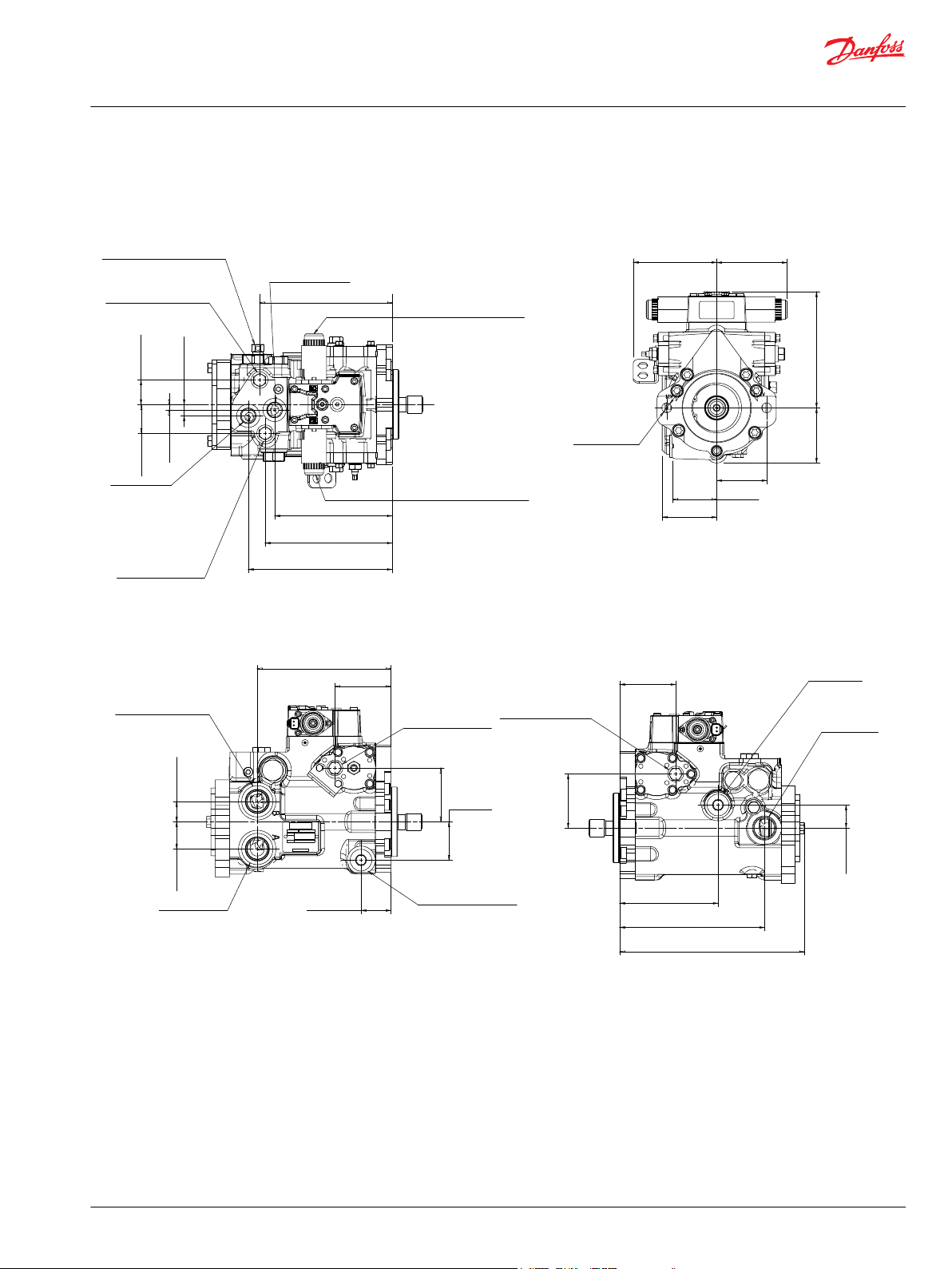
P108771-
121.9 ± 2.5
103 ± 1.5
169.8 ± 2.5
80.8 ± 1.5
73 ± 0.18
64 ± 1.5
Case outlet
(alternate)
79.8 ± 1.5
System ports
2x Ø14.27
+0.25
-0.89
193.5 ± 2.5
Control manual override C1
Control manual override C2
From remote filter
ISO 11926-1 7/8-14
210 ± 2.5
185.4 ± 2.5
171.4 ± 2.5
35.6 ± 1.5
Bypass valve
(full open at two revolutions)
System gauge port A
ISO 11926-1 9/16-14
16.8 ± 1
42.2 ± 1.5
8.1 ± 1
System gauge port B
ISO 11926-1 9/16-14
System port B
ISO 11926-1 1 5/16-12
System port A
39.6 ± 1.5
195.6 ± 2.5
ISO 11926-1 1 5/16-12
30 ± 1.5
81.9 ± 1.5
43.7 ± 1.5
Servo gauge port M5
ISO 11926-1 1 9/16-18
78.7 ± 1.5
55.9 ± 1.5
Servo gauge port M4
ISO 11926-1 1 9/16-18
Case outlet (alternate)
ISO 11926-1 1 1/16-12
81.9 ± 1.5
269.5 ± 2.5
33.5 ± 1.5
Case outlet
ISO 11926-1
1 1/16-12
Charge pump inlet
ISO 11926-1
1 5/16-12
78.7 ± 1.5
211.8 ± 2.5
143.8 ± 2.5
Charge filtration port E
Charge gauge port for remote filtration
with or w/o charge pump option
To remote filter
ISO 11926-1 7/8-14
Charge filtration port D
Charge gauge port for
remote filtration with
charge pump option
Technical Information
Series 40 M46 Pumps
Control Options - Installation Drawings
HC EDC Control
©
Danfoss | March 2017 L1001029 | BC00000176en-US0209 | 59
Page 60

177.8 max.
[7.00]
141.7 [5.58]
To ports
49.0 [1.93]
118.1 [4.65]
39.6 [1.56]
to ports
49.0 [1.93]
118.1 [4.65]
39.6 [1.56]
to ports
352.3 [13.87]
421.4 [16.59]
39.6 [1.56]
to ports
Port X2
Port X1
7/16 -20*
Control pressure ports
(2) places
Port X2 (front)
Port X1 (front)
7/16 - 20*
Control pressure ports
(4) places
Port X2 (rear)
Port X1 (rear)
Side view
Tandem pump with HDC
Side view
Variable pump with HDC
View X
Front view
Variable pump with HDC
X
P100631
Technical Information
Series 40 M46 Pumps
Control Options - Installation Drawings
Hydraulic displacement control (HDC)
Contact Danfoss for individual dimension drawings.
60 | © Danfoss | March 2017 L1001029 | BC00000176en-US0209
Page 61

177.8 max.
[7.00]
124.2 max.
[4.89]
Side view
Variable pump with EDC
(Packard Weather-Pack connector)
View X
Front view
Variable pump with EDC
(Packard Weather-Pack connector)
Packard "Weather Pack" shroud connector
on 76 mm [3 in] lead wires
4-way (Dual Coil PCP) mates with Packard 12015797 connector
X
A
B
C
D
Danfoss
mating parts kit
part no. K03384
(female terminals)
V
View V
P100632
Packard Weather-Pack
4-way tower connector
(male terminals)
A
B
C
D
138.4 [5.45]
Side view
Tandem pump with EDC
(MS connector)
124.2 max.
[4.89]
332.0 [13.07]
124.2 max.
[4.89]
U
View U
97.5
[3.84]
141.7
[5.58]
7/8 - 20 UNEF
MS53102C connector
mates with MS3106E-14S-2S
connector
7/8 - 20 UNEF
MS53102C connector
mates with MS3106E-14S-2S
connector
Pump
P108516
CG
CN
1
2
Deutsch Connector
Technical Information
Series 40 M46 Pumps
Control Options - Installation Drawings
Option CE
Electronic displacement control (EDC)
Options CG, CN
Electronic displacement control (EDC)
©
Danfoss | March 2017 L1001029 | BC00000176en-US0209 | 61
Page 62

Connector per
ISO 4400
(2) Places
8.78
[223]
B
A
B
A
B
A
Side view
Tandem pump with FNR control
Side view
Variable pump with FNR control
View X front view
Variable pump with FNR control
X
Solenoid Plug Face
P109487
not connected
Terminal 1
Terminal 2
Technical Information
Series 40 M46 Pumps
Control Options - Installation Drawings
Options DA, DB
Three-position electric displacement control (FNR)
62 | © Danfoss | March 2017 L1001029 | BC00000176en-US0209
Page 63

Technical Information
Series 40 M46 Pumps
Reference Literature
Literature
M46 systems may consist of a variety of pump, motor, valve and control combinations. Refer to the
literature listed below for product information and specifications for M46 pumps and other Danfoss
components.
M46 Pumps literature
•
Series 40 M46 Single Pumps Service Manual 11026743
•
Series 40 M46 Tandem Pumps Service Manual 11029852
Propel Systems related Literature
•
Series 40 Motors Technical Information 520L0636
•
L&K Frame Motors Technical Information 520L0627
•
JS 1000, JS 6000 Joystick Grips Technical Information 520L0872
•
PLUS+1 Controller Family Technical Information 520L0719
Hydraulic Systems Guidelines
•
Hydraulic Fluids and Lubricants Technical Information 520L0463
•
Pressure and Speed Limits BLN-9884
•
Design Guidelines for Hydraulic Fluid Cleanliness 520L0467
•
Experience with Biodegradable Hydraulic Fluids, Technical Information 520L465
•
Pressure and Speed Limits BLN-9884
•
Selection of Driveline Components BLN-9885
©
Danfoss | March 2017 L1001029 | BC00000176en-US0209 | 63
Page 64

Danfoss
Power Solutions GmbH & Co. OHG
Krokamp 35
D-24539 Neumünster, Germany
Phone: +49 4321 871 0
Danfoss
Power Solutions ApS
Nordborgvej 81
DK-6430 Nordborg, Denmark
Phone: +45 7488 2222
Danfoss
Power Solutions (US) Company
2800 East 13th Street
Ames, IA 50010, USA
Phone: +1 515 239 6000
Danfoss
Power Solutions Trading
(Shanghai) Co., Ltd.
Building #22, No. 1000 Jin Hai Rd
Jin Qiao, Pudong New District
Shanghai, China 201206
Phone: +86 21 3418 5200
Products we offer:
Comatrol
www.comatrol.com
Turolla
www.turollaocg.com
Hydro-Gear
www.hydro-gear.com
Daikin-Sauer-Danfoss
www.daikin-sauer-danfoss.com
Bent Axis Motors
•
Closed Circuit Axial Piston
•
Pumps and Motors
Displays
•
Electrohydraulic Power
•
Steering
Electrohydraulics
•
Hydraulic Power Steering
•
Integrated Systems
•
Joysticks and Control
•
Handles
Microcontrollers and
•
Software
Open Circuit Axial Piston
•
Pumps
Orbital Motors
•
PLUS+1® GUIDE
•
Proportional Valves
•
Sensors
•
Steering
•
Transit Mixer Drives
•
Danfoss Power Solutions is a global manufacturer and supplier of high-quality hydraulic and
electronic components. We specialize in providing state-of-the-art technology and solutions
that excel in the harsh operating conditions of the mobile off-highway market. Building on
our extensive applications expertise, we work closely with our customers to ensure
exceptional performance for a broad range of off-highway vehicles.
We help OEMs around the world speed up system development, reduce costs and bring
vehicles to market faster.
Danfoss – Your Strongest Partner in Mobile Hydraulics.
Go to www.powersolutions.danfoss.com for further product information.
Wherever off-highway vehicles are at work, so is Danfoss. We offer expert worldwide support
for our customers, ensuring the best possible solutions for outstanding performance. And
with an extensive network of Global Service Partners, we also provide comprehensive global
service for all of our components.
Please contact the Danfoss Power Solution representative nearest you.
Local address:
Danfoss can accept no responsibility for possible errors in catalogues, brochures and other printed material. Danfoss reserves the right to alter its products without notice. This also applies to products
already on order provided that such alterations can be made without changes being necessary in specifications already agreed.
All trademarks in this material are property of the respective companies. Danfoss and the Danfoss logotype are trademarks of Danfoss A/S. All rights reserved.
©
Danfoss | March 2017 L1001029 | BC00000176en-US0209
 Loading...