

Page 1
Installation guide
Dual pressure switch
Type KP 44
Ambient temperatures
060R9766
t1 min. -40 °C (-40 °F)
t1 max. 65 °C (150 °F)
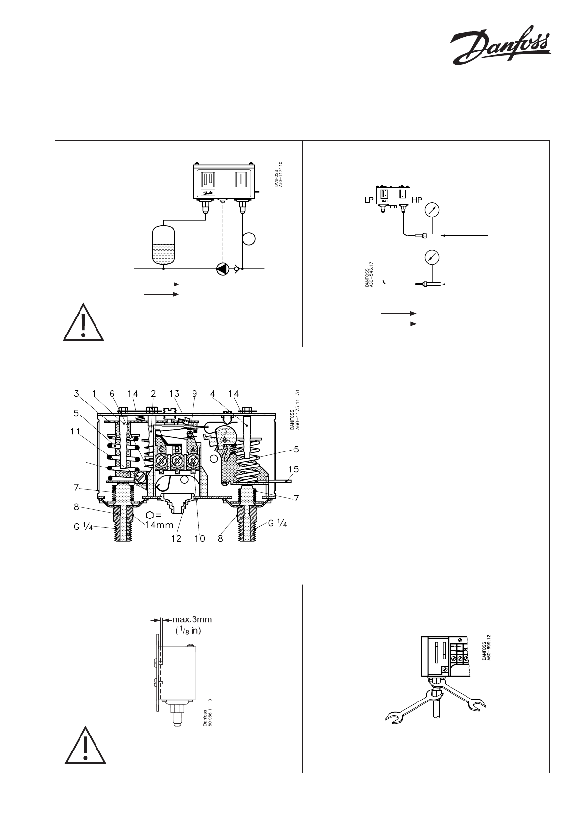
Caution: Do not mount the control in a p osition
where dirt, sediment or oil will aect the operatio
of the control.
Connections
Test pressure (p
Control Safety
Control PS/MWP 17 bar Pe (245 psig)
Safety PS/MWP 17 bar Pe (245 psig)
1. Lefthand pressure setting spindle
2. Dierential setting spindle
3. Main arm
4. Righthand pressure setting spindle
5. Main spring
6. Dierential spring
7. Bellows
8. Pressure connections
9. Contact system
10. Terminal
11. Earth terminal
12. Cable entr y
13. Tumbler
14. Locking plate
15. Impulse lever
test
)
P
max.
test
19 bar P
P
max.
test
25 bar P
(275 psig)
e
(362 psig)
e
060R9766
The switch in the KP has a snap-action function and the
bellows moves only when the cut-in or cut-out value is
reached.
Enclosure
Caution: The mounting panel must be plane
to avoid damage of control.
© Danfoss A/S (AC-MCI /jmn), 2014-01 DKRCC.PI.CD0.B2.02 / 520H8364 1
Mounting
Page 2
Caution:
Disconnect power supply before wiring connections are made or service to avoid possible electrical shock or
damage to equipment. Do never touch live parts with your ngers or with any tool.
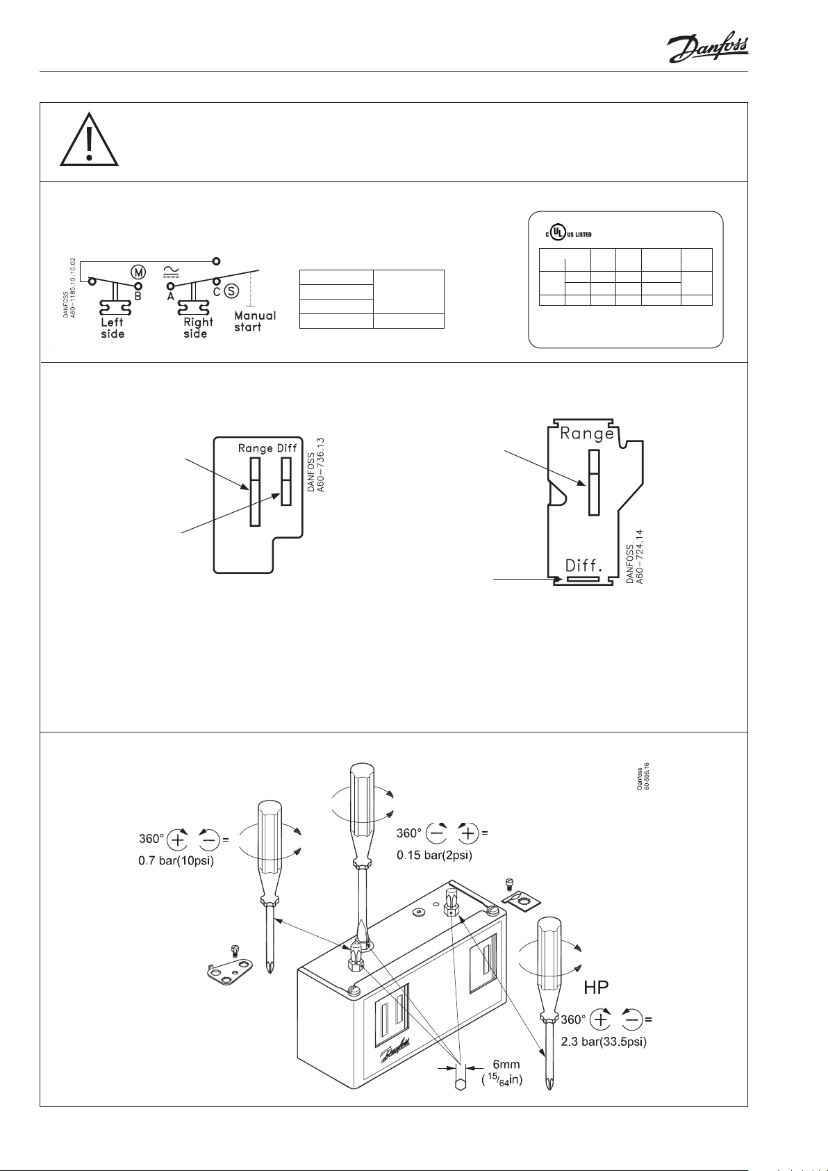
Electrical connections
Electrical ratings
AC 1: 16 A
AC 3: 16 A
AC 15: 10 A
DC 13: 12 W 220 V
400 V
Setting
CONTROL side setting SAFETY side setting
1. Adjust range spindle to
desired CUT-IN value
1. Adjust range
spindle to desired
CUT-OUT value.
2. Adjust dierential
spindle to desired
DIFFERENTIAL (DIFF.)
value
2. DIFFERENTIAL (DIFF.)
is xed. Value printed
on scale plate.
When used acc. to UL regulations
Listed refrigeration
Voltage FLALRAResist.
AC DC
240
120
Use copper wire only
Tightening torque 20 lb.in.
controller 61B5
8 48 8 A
16 96 16 A
240 12 W
load
Pilot
duty
3 A
CUT-IN equals CUT-OUT minus CUT-IN equals CUT-OUT plus
DIFFERENTIAL DIFFERENTIAL
Example: Example:
CUT-OUT – DIFF. = CUT-IN CUT-OUT + DIFF. = CUT-IN
8 bar (116 psi) – 2 bar (29 psi) = 6 bar (87 psi) 4 bar (58 psi) + 1 bar (15 psi) = 5 bar (73 psi)
Adjustment
Control side setting Control side dierential
Safety side setting
Note:
Remove lockplate before adjustment
Replace lockplate after adjustment (if desired).
2 DKRCC.PI.CD0.B2.02 / 520H8364 © Danfoss A/S (AC-MCI /jmn), 2014-01
 Loading...