

Page 1
Data sheet
Pressure switch and Thermostat
KP and KPI
The KP and KPI pressure switches and
thermostats are used for control, monitoring
and alarm systems in a wide variety of industry
applications.
KP pressure switches are mainly used for gaseous
fluid whereas KPI pressure switches are more
for liquid and gaseous fluid. The products
are available in IP30 enclosure as well as IP55
enclosure.
The KP pressure range include special designed
pressure switches and limiters for steam boilers
and other heating applications.
For water pump control and protection (dry run)
the dual pressure switch KP44 is suitable and
secure improved life time of the water pump.
Features • Wide setting range
• Shock and impact resistant
• Snap action electrical contacts minimize
chatter, bounce, and wear, and ensure long
term electrical and mechanical reliability
• Small dimensions - space saving and easy
to install in panels
• Electrical connection from front
of the unit makes rack mounting easier
and also saves space
• Suitable for alternating current
and direct current
• Single pressure switches and thermostats are
fitted with a single pole double throw contact
system (SPDT)
• Can be used for both liquids and gases (KPI)
Approvals CE-marked in accordance with LVD 2014/35/EU:
EN 60947-1, EN 60947-4-1, EN 60947-5-1
Underwriters Laboratories Inc., UL
• Manual trip function enables electrical
connections verification without any tools or
pressure changes in the application
• Versions with automatic and manual
reset available
• For demineralized water, there are special KP
models with wetted parts made of stainless
steel (AISI 316L)
China Compulsory Certificate, CCC
(excluding boiler versions)
GOST (excluding KPI)
© Danfoss | DCS (rm) | 2019.12
IC.PD.P10.F9.02 | 1
Page 2
Data sheet | Pressure switch and Thermostat, KP and KPI
Technical data
Single pressure switch
Description KP 35, KP 36 KPI 35, KPI 36 KPI 38
Ambient temperature [°C] -40 – 65 °C (for max. 2 hours up to 80 °C)
Media temperature [°C] -40 – 100 °C
Fluid Gaseous media
Bellows
Parts in contact
with fluid
Contact system
Contact load, Silver
Contact load,
Gold plated contact set
Enclosure, IP30 grade
Enclosure, IP44 grade Mounted as IP30 plus fitting of top cover, code no. 060-109766
Enclosure, IP55 grade
Cable entry Rubber cable gland entry for 6 – 14 mm diameter cables
Mounted on back
plate / wall bracket
Mounted on angle bracket Not recommended in areas where vibrations occur
Pressure
connector
Phosphor bronze
or Stainless steel
Free-cutting steel
(nickel plated)
or Stainless steel
Single-pole double throw (SPDT)
Alternating current:
AC-1: 16 A, 400 V
AC-3: 16 A, 400 V
AC-15: 10 A, 400 V
Direct current:
DC-13: 12 W, 220 V
See information page 15
Unit must be mounted on a flat surface / a flat fitting and all unused holes
covered
Unit mounted in a special IP55 enclosure, code no.
060-033066 or 060-062866
Vibration proof in the range 0 – 1000 Hz, 4 g [1 g = 9.81 m/s2
Gaseous media and
liquids
Phosphor bronze Stainless steel
Brass Free-cutting steel (nickel plated)
Alternating current:
AC-1: 10 A, 440 V
AC-3: 6 A, 440 V
AC-15: 4 A, 440 V
Direct current:
DC-13: 12 W, 220 V
KP 34, KP 35, KP 36,
KP 37 boiler version
Steam, air, gaseous
media & liquids
Alternating current:
AC-1 : 16 A, 400 V
AC-3 : 16 A, 400 V
AC-15 : 10 A, 400 V
Direct current:
DC-13: 12 W, 220 V
© Danfoss | DCS (rm) | 2019.12 IC.PD.P10.F9.02 | 2
Page 3
Data sheet | Pressure switch and Thermostat, KP and KPI
Ordering Pressure switch, types KP 35 and KP 36
Permissible
Typ e
Setting
range P
e
Differential
[bar] [bar] [bar] [bar]
-0.2 – 7.5 0.7 – 4.0 17 22 G 1⁄4 A silver
KP 35
-0.2 – 7.5 0.7 – 4.0 17 22 G 1⁄4 A gold-plated 060-50476 6
-0.2 – 7.5 0.7 – 4.0 17 22 G 1⁄4 A silver 060-538666 2)
-0.2 – 7.5 0.7 – 4.0 17 22 G 1⁄4 A silver 060-450366 3)
2.0– 14.0 0.7 – 4.0 17 22 G 1⁄4 A silver
2.0– 14.0 0.7 – 4.0 17 22 G 1⁄4 A gold 060-113 766
KP 36
2.0– 14.0 0.7 – 4.0 17 22 G 1⁄4 A silver 06 0-538766 2)
4.0 – 12.0 0.5 – 1.6 17 22 G 1⁄4 A silver 06 0-122166
4.0 – 12.0 0.5 – 1.6 17 22 G 1⁄4 A gold 06 0-114 4 66
4.0 – 12.0 0.5 – 1.6 17 22 G 1⁄4 A silver 06 0-450166 3)
1
) Available only in Asia market
2
) IP55 transparent enclosure
3
) Stainless steel version, IP55 non-transparent enclosure
Pressure switch, types KPI 35 – KPI 38
Setting
Typ e
range P
[bar] [bar] [bar] [bar]
-0.2 – 8.0 0.4 – 1.5 18 18 G 1⁄4 A silver 06 0-121766
KPI 35
-0.2 – 8.0 0.4 – 1.5 18 18 G 1⁄4 A gold-plated 060-3164 66
-0.2 – 8.0 0.5 – 2.0 18 18 G 1⁄4 A silver 06 0-1219 66
-0.2 – 8.0 0.4 – 1.5 18 18 G 1⁄4 A silver 060 -315766 1)
4 .0– 12.0 0.5 – 1.6 18 18 G 1⁄4 A silver 06 0-118966
KPI 36
4.0 – 12.0 0.5 – 1.6 18 18 G 1⁄4 A gold-plated 0 60 -113866
2.0 – 12.0 0.5 – 1.6 18 18 G 1⁄4 A silver 060-3169 66
2.0 – 12.0 0.5 – 1.6 18 18 G 1⁄4 A silver 06 0-3193 66 2)
KPI 38
1
) IP55 transparent enclosure
2
) IP55 non-transparent enclosure
8.0 – 28.0 1.8 – 6.0 30 30 G 1⁄4 A silver 060-508166
8.0 – 28.0 1.8 – 6.0 30 30 G 1⁄4 A silver 060-54186 6 2
e
Differential
operating
pressure P
Permissible
operating
pressure P
pressure
e
e
Max.
test
Max.
test
pressure
Pressure
connection
Pressure
connection
Contact
material
Contact
material
Code no.
060-113 366
060-113 391 1)
060-110866
060-110891 1)
Code no.
Pressure switch, types KP 34 – KP 37, boiler version
Typ e
KP 34
KP 35
KP 36
KP 37
Setting
range pe
Differential
Reset
[bar] [bar] [bar] [bar]
0.1 – 1.0 0.1 – 0.4 Automatic G 1⁄2 A 4.0 silver 0 60-216 466
0.1 – 1.0 0.2 Manual G 1⁄2 A 4.0 silver 060 -216366
0.4 – 3.4 0.4 – 2.2 Automatic G 1⁄2 A 10 silver 060-216666
0.4 – 3.4 0.5 Manual G 1⁄2 A 10 silver 060-216566
1.0 – 10.0 0.7 – 4.0 Automatic G 1⁄2 A 17 silver 060 -21596 6
1.0 – 10.0 0.7 Manual G 1⁄2 A 17 silver 060-216066
4.0 – 20.0 1.8 – 3.1 Automatic G 1⁄2 A 28 silver 060 -216166
4.0 – 20.0 3.0 Manual G 1⁄2 A 28 silver 060 -216266
Pressure
connection
Max. test
pressure
Contact
material
Code no.
© Danfoss | DCS (rm) | 2019.12 IC.PD.P10.F9.02 | 3
Page 4

Data sheet | Pressure switch and Thermostat, KP and KPI
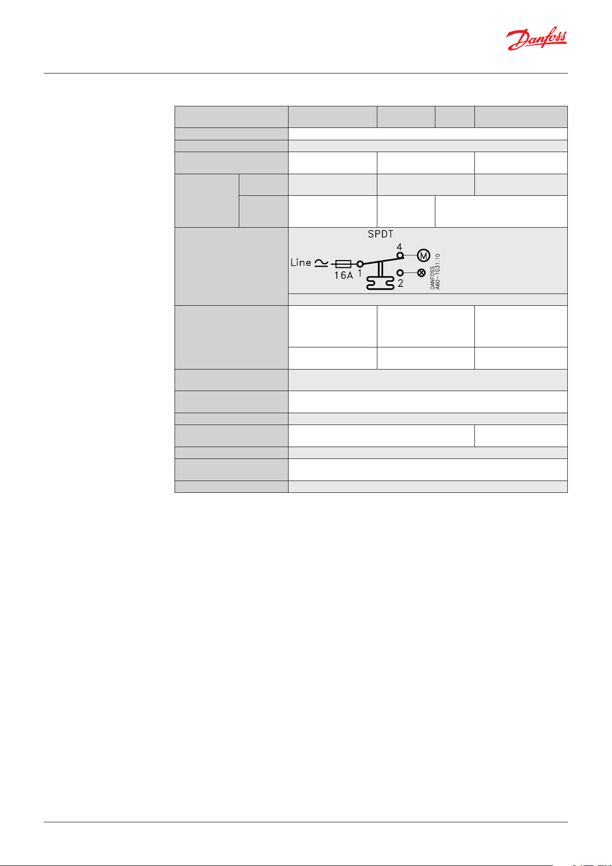
Contact system
and application
Setting
Switch type – single pole double throw Switch action Application
1. Terminal 1 – 4 close high and open low
SPDT
Terminal 1 – 2 can be used as low
pressure alarm
2. Terminal 1 – 2 open high and close low
Terminal 1 – 4 can be used as high
pressure alarm
1. Low pressure cut-out
2. High pressure cut-out
Diff.
Range
Note:
For low pressure switches
the restart pressure is equal
to cut-out pressure plus
differential value.
Cut-in and cut-out pressures of the system
should always be checked with an accurate
pressure gauge.
Pressure setting for switches with automatic
reset.
1. Set the cut-in pressure on the “CUT-IN”
scale (range scale).
2. Set the differential on the “DIFF” scale.
The cut-out pressure must be above absolute
vacuum (pe = -1 bar).
For high pressure switches the restart pressure
is equal to cut-out pressure minus differential.
Pressure switches with manual reset
Set the cut-out presure on the “CUT-OUT”
scale (range scale).
High pressure limiters can be manually reset
when the pressure is equal to the stop pressure
minus the differential.
© Danfoss | DCS (rm) | 2019.12 IC.PD.P10.F9.02 | 4
Page 5
60-973.13.10
60-972.13.10
13 122
13
60-776.17.10
60-974.12.10
4 3 1 13 2 12
13 2 12
Data sheet | Pressure switch and Thermostat, KP and KPI
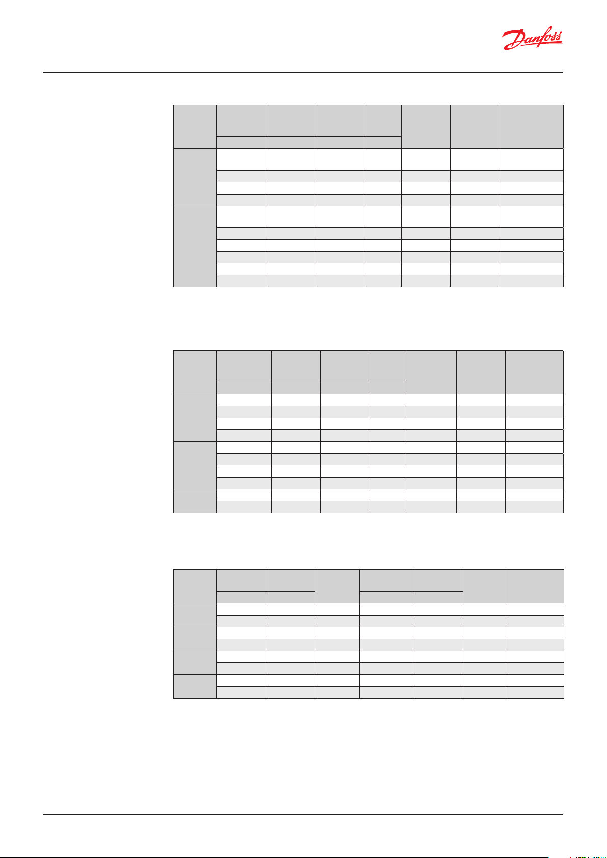
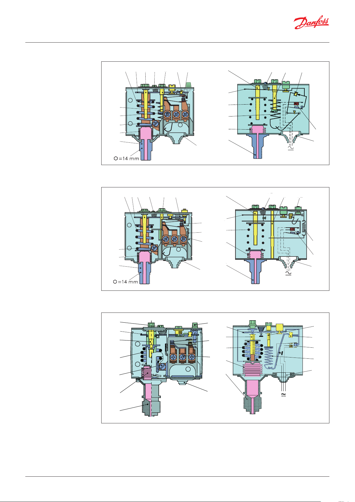
Design / Function
1. Setting spindle
2. Differential setting
spindle
3. Main arm
4. Main spring
5. Differential spring
6. Bellows
7. Pressure connector
8. Contact system
9. Connection terminals
10. Earth terminal
11. Cable entry
12. Omega spring (KPI)
12. Tumbler (KP)
13. Locking screw
14. Manual reset
Key sketch of KP pressure switch
4
3
1 13 2 12 8
5
4
9
10
6
7
Key sketch of KPI pressure switch
2 4 1
10
6
7
1
3
Danfoss
2
1
4
4
1
2
Danfoss
5
6
11
7
8
11
1
Danfoss
8
5
9
3
2
4
1
Danfoss
4
6
5
8
11
7
11
Key sketch of KP pressure switch, boiler version
3
3
1
2
4
10
6
7
The contact system in KP pressure switches has
a snap function. This means that the bellows
is active only when the cut-in or cut out value
is reached.
The bellows is connected to the pressure of the
controlled plant via the connector (7).
4 1
14
11
Danfoss
60-1356.11.10
3
1
8
4
9
6
4
1
2
7
Danfoss KPI pressure switches are designed
so that the bellows moves in the same
proportion as the pressure switches change.
To ensure a snap function on contact change
over, an omega spring is located between
bellows and contact system.
Danfoss
60-1355.11.10
2
12
8
5
11
© Danfoss | DCS (rm) | 2019.12
IC.PD.P10.F9.02 | 5
Page 6

84
44
6128 – 30
Danfoss
60-1358.11
60-1357.11
60-221.13
60-221.13
Danfoss
60-221.13
Data sheet | Pressure switch and Thermostat, KP and KPI
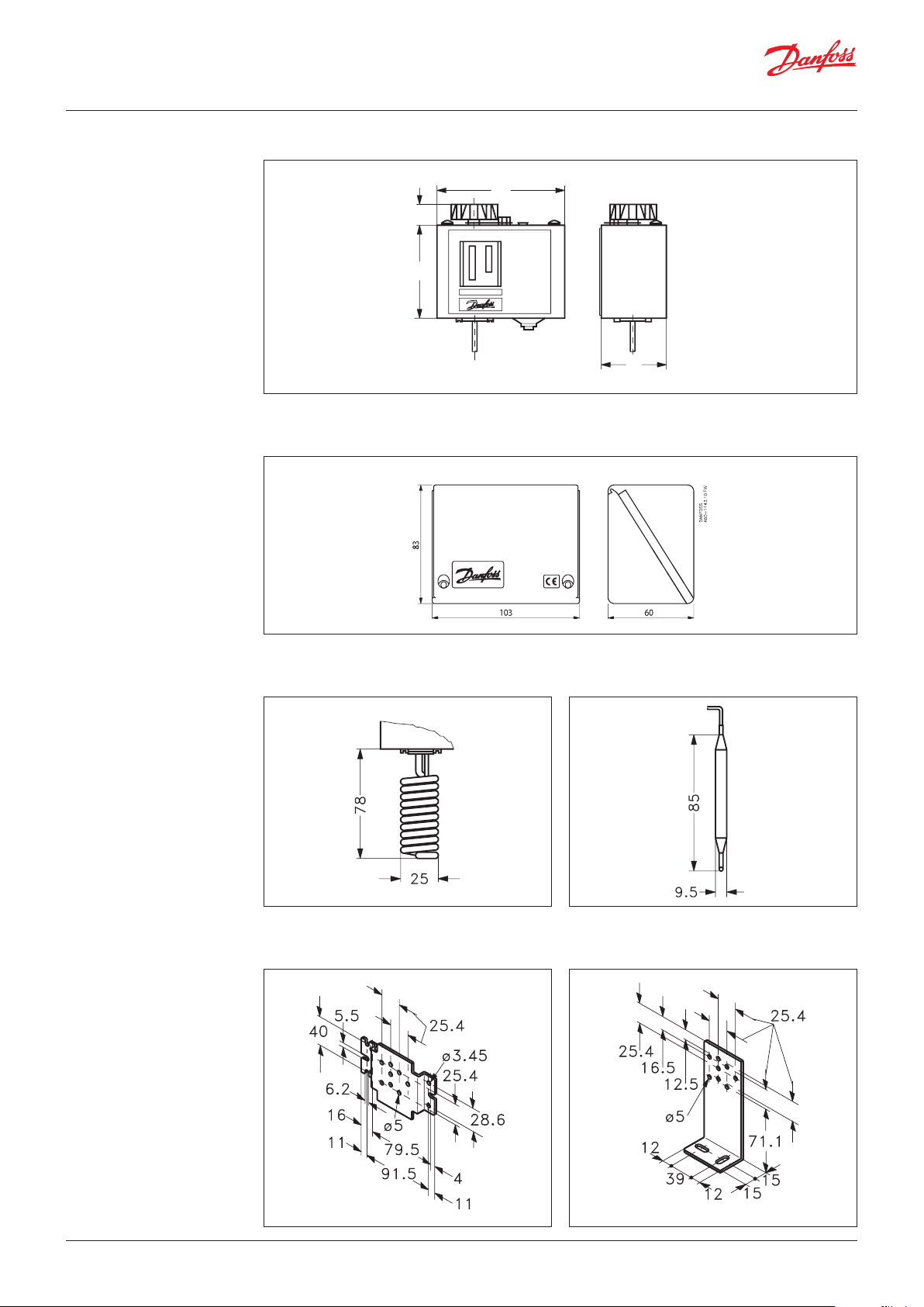
Dimensions [mm]
and weights [kg]
Pressure switch, types KP 35, KP 36, KPI 35, KPI 36 and KPI 38
Standard IP30 housing
=14
IP55 enclosure
Danfoss
60-9059.10
Net weight approx. 0.3 kg
Dimensions [mm]
and weights [kg]
(Boiler version)
Wall bracket Angle bracket
Danfoss
Pressure switch, types KP 35 and KP 36 Pressure switch, type KP 34
Danfoss
© Danfoss | DCS (rm) | 2019.12
Rubber Grommet
for 6 – 14 mm cable
G 1/2 A
Net weight approx. 0.34 kg
Rubber Grommet
for 6 – 14 mm cable
G 1/2 A
Net weight approx. 0.43 kg
IC.PD.P10.F9.02 | 6
Danfoss
Page 7

Data sheet | Pressure switch and Thermostat, KP and KPI
Accessories for KP pressure switches
Part Symbol Description Tot al Code no.
Brackets
with mounting
screws
and washers
Screwed
cable entry
Sealing screw For sealing the setting on KP 2 06 0-105766
Top cove r
Protective cap
Wall bracket for KP 1 060-105566
Angle bracket for KP 1 060-105666
PG 13.5 with special nut
For 6 –14 mm diameter cables
If a bracket is mounted on the backplate of the housing,
the KP thermostats will have an IP44 grade of enclosure.
The cover protects the setting spindles
Protective cap for KP pressure switches and thermostats.
To protect the unit against rain and humidity.
Grade of enclosure: IP44
Material: Polyethylene
Max. ambient temperature: 65 °C
Min. ambient temperature: -40 °C
1 060-105966
1 06 0-10 9766
1 060 -003166
IP55
nontransparent
enclosure
IP55
transparent
enclosure
If the unit risk being exposed to heavy water influence
a better grade of enclosure can be achieved when
mounting product in a special IP55 enclosure
If the unit risk being exposed to heavy water influence
a better grade of enclosure can be achieved when
mounting product in a special IP55 enclosure
1 060-033066
1 060-062866
© Danfoss | DCS (rm) | 2019.12 IC.PD.P10.F9.02 | 7
Page 8

Data sheet | Pressure switch and Thermostat, KP and KPI
Technical data Dual pressure switch
Ambient temperature [°C] - 40 – 65 °C (for max. 2 hours up to 80 °C)
Media temperature [°C] Max. 100 °C
Fluid Liquids
Parts in contact with fluid
Contact system
Contact load, Silver
IP level IP22
Cable entry Rubber cable gland entry for 6 – 14 mm diameter cables
Mounted on backplate or wall bracket Vibration-proof in the range 0 – 1000 Hz, 4 g [1 g = 9.81 m/s2
Mounting on angle bracket Not recommended for areas where vibration occurs
Bellows Phosphor bronze, CuSn6
Pressure connector Free-cutting steel (nickel plated)
left
side
Alternating current:
AC-1: 16 A, 400 V
AC-3: 16 A, 400 V
AC-15: 10 A, 400 V
Direct current:
DC-13: 12 W, 220 V
right
side
manual
start
Ordering
Pressure switch, type KP 44
Pressure range Differential Permissible
[bar] [bar] [bar] [bar] [bar] [bar]
2.0 – 12.0 0.5 – 6.0 0.7 – 4.0 1.0
operating
pressure p
Left side: 17
Right side: 17
e
Right side: 19
Max. test
pressure
Left side: 25
Pressure
connection
2 × G 1⁄4 A silver 0 60- 001366
Contact
material
Code no.Control Safety Control Safety
© Danfoss | DCS (rm) | 2019.12 IC.PD.P10.F9.02 | 8
Page 9

60-1175.12.10
1 6 14 2 13 9 4 14
12 10 8
Data sheet | Pressure switch and Thermostat, KP and KPI
Design / Function Key contact system of KP 44 pressure switch
3
1. Lefthand pressure
setting spindle
5
2. Differential setting
spindle
11
3. Main arm
4. Righthand pressure
setting spindle
5. Main spring
6. Differential spring
7. Bellows
8. Pressure connections
7
9. Contact system
10. Terminal
8
11. Earth terminal
12. Cable entr y
13. Tu mb ler
14. Locking plate
15. Impulse lever
Water supply from reservoir or well
The contact system in the KP 44 has a snapaction function and allows the bellows moves
only when the cut-in or cut-out value is reached.
If water is running short in the well or reservoir,
the pump will no longer be able to increase the
pressure to the cut-out value. Consequently the
pump will keep running - perhaps without water.
However, the KP 44 pressure switch will stop the
pump as soon as the righthand bellows pressure
drops below the safety cut-out setting.
The pump can be started again by lifting the
impulse lever. The pump will continue to operate
when the impulse lever is released, provided that
the righthand bellows pressure is higher than the
safety cut-out setting plus a fixed differential
of 1 bar. If this is not the case, the pump
will cut-out again indicating insufficient
water supply.
Danfoss
5
15
7
Pressurized water supply direct to pump
When water supply fails on the inlet side,
the pump will no longer be able to boost the
pressure to the cut-out value. Consequently the
pump will keep running - perhaps without water.
However, the KP 44 pressure switch will stop the
pump as soon as the pressure in the pump
suction line drops below the safety cut-out
setting. The pump will automatically start again
when the pump suction pressure has reached
the level of 1 bar above the safety cut-out
setting.
Automatic start-up will only take place if the
righthand bellows is connected to the pump
suction line. Air pockets should be avoided to
prevent the pump from starting up on air
pressure rise, without the presence of water.
In a hydrophore system where water is pumped
from a well or an open tank, both bellows are
connected to a pressure outlet on the air
side in the pump pressure line, if possible.
© Danfoss | DCS (rm) | 2019.12
In a booster system receiving pressurized
water the righthand bellows is connected
• to the low pressure side of the pump
forautomatic start-up
• to the high pressure side of the pump
for manual start-up
The lefthand bellows is always connected
to the high pressure side of the pump.
IC.PD.P10.F9.02 | 9
Page 10

60-1178.12
Data sheet | Pressure switch and Thermostat, KP and KPI
Setting
Dimensions[mm]
and weights [kg]
Safety cut-out setting
The righthand bellows will automatically cut-out
the pump at the safety cut-out setpoint.
Automatic start-up, if any, will take place when
the pressure has reached the level of 1 bar above
the setpoint. Manual cut-in is made by lifting the
impulse lever and releasing it again when the
The safety cut-out setpoint is normally
determined by the static pressure (the water
column). However, in order to avoid disturbing
signal interaction, care should be taken to ensure
that the safety cut-out setting is at least 1.5 bar
lower than the control pressure cut-in setting.
See table with pressure setting examples below.
pressure has increased by min. 1 bar.
Required tap water pressure ≥ 2.3 bar ≥ 4.0 bar ≥ 5.0 bar ≥ 8.0 bar
Control pressure cut-out setting 3.0 bar 5.0 bar 8.0 bar 12 bar
Differential 0.7 bar 1.0 bar 3.0 bar 4.0 bar
Control pressure cut-in setting 2.3 bar 4.0 bar 5.0 bar 8.0 bar
Max. safety cut-out setting 0.8 bar 2.5 bar 3.5 bar 6.0 1 bar
1)
6.0 bar is the normal max. setpoint
Control pressure settings
Control pressure cut-out setpoint
is set on the lefthand pressure setting scale.
The differential is set between 0.7 and 4 bar.
The control pressure cut-in setting will be the
cut-out control pressure less the differential.
Danfoss
Net weight approx. 0.5 kg
Accessories for KP 44
pressure switches
Part Symbol Description Tot al Code no.
Wall bracket 1 060-105566
Brackets with
mounting
screws and
washers
Screwed
cable entry
Sealing screw For sealing the setting on KP 2 06 0-10576 6
Angle bracket 1 060-105666
Screwed cable entry
Pg 13.5 with special nutfor 6 – 14 mm cables
1 060-105966
© Danfoss | DCS (rm) | 2019.12
IC.PD.P10.F9.02 | 10
Page 11

Data sheet | Pressure switch and Thermostat, KP and KPI
Technical data
Single thermostat
Ambient temperature [°C] - 40 – 65 °C (for max. 2 hours up to 80 °C)
Sensor material Tinned copper Cu/Sn5
Contact system
Single-pole double throw (SPDT)
Alternating current:
AC-1: 16 A, 400 V
Contact load, Silver
Contact load,
Gold plated contact set
Enclosure, IP30 grade
Enclosure, IP44 grade Mounted as IP30 plus fitting of top cover, code no. 060-109766
Enclosure, IP55 grade
Cable entry Entry for 6 – 14 mm diameter cable
Mounted on backplate or wall bracket Vibration-proof in the range 0 – 1000 Hz, 4 g [1 g = 9.81 m/s2
Mounted on angle bracket Not recommended for areas where vibration occurs
AC-3: 16 A, 400 V
AC-15: 10 A, 400 V
Direct current:
DC-13: 12 W, 220 V
See Information page 15
Unit must be mounted on a flat surface / a flat fitting
and all unused holes covered
Unit mounted in a special IP55 enclosure, code no. 060-033066
or 060-062866. Exception: KP 75
Ordering
Thermostat, types KP 75 – KP 81
Typ e
KP 75
KP 78 30 – 90 5 – 15 150 2 silver 060L118466
KP 79 50 – 100 5 – 15 150 2 silver 060L112666
KP 81 80 – 150 7 – 20 200 2 silver 060L112566
KP 81 80 – 150 7 – 20 200 3 silver 060L118366
KP 81 80 – 150 7 – 20 200 5 silver 060L117066
KP 81
(max. reset)
Setting range Differential
[°C] [°C] [°C] [m]
0 – 40 3 – 10 80 Room sensor silver 060L1212 66
0 – 40 3 – 10 80 Room sensor gold-plated 060L117166
80 – 150
8
(max. reset)
Max. sensor
temperature
200 2 silver 060L115566
Capillary
tube length
Contact
material
Code no.
© Danfoss | DCS (rm) | 2019.12 IC.PD.P10.F9.02 | 11
Page 12

7
11
10
60-971.13.10
12118
1
4
5
6
8
7
12
11
Danfoss
60-970.12.10
8
7
12
11
12
7
Data sheet | Pressure switch and Thermostat, KP and KPI
Design / Function Key sketch of KP thermostat, types KP 78, KP 79, KP 81
1. Temperature setting
spindle
2. Differential setting
spindle
3. Main arm
4. Main spring
5. Differential spring
6. Bellows
7. Sensor
8. Contact system
9. Connection terminals
10. Earth terminal
11. Cable entry
12. Tumbler
10
7
12
2
3
4
4
5
5
9
8
9
6
6
1
2
3
4
5
6
Danfoss
KP 75 room sensor
The contact system in KP thermostats has a snap
function. This means that the bellows is active
only when the cut-in or cut-out value is reached.
12
8
11
7
Charges
6. Bellows
7. Sensor
13. Capillary tube
Setting
© Danfoss | DCS (rm) | 2019.12
7
oss
6
13
Danfoss
60-909.11.10
Thermostats with automatic reset
Set the upper limit temperature on the range
scale. Then set the differential on the DIFF scale.
The temperature set on the range scale is also
the temperature at which contact changeover
re-occurs on rising temperature.
The contacts changeover when the temperature
has fallen to a value lower than that set on the
DIFF scale.
If at lower settings the plant will not start/stop,
the reason might be that the differential has
been set too high.
Absorption charge
The charge consists partly of a superheated gas
and partly of a solid substance with a large
absorption surface.
The solid substance is concentrated in the sensor
(7), and consequently it is always the sensor that
comprises the temperature-regulating part of
the thermostatic element.
The sensor can be placed both warmer or colder
than the thermostat housing and capillary tube.
However, placing it in an ambient temperature
higher or lower than 20 °C can affect the
accuracy of the scale.
Thermostats with minimum reset
Set the temperature on the range scale.
The differential setting is fixed.
Min. reset units will restart after the temperature
at the thermostat sensor has risen by a value
greater than that of the fixed differential.
Thermostats with maximum reset
Set the stop temperature on the range scale.
The differential setting is fixed.
Max. reset units will restart after the temperature
at the thermostat sensor has fallen by a value
greater than that of the fixed differential.
IC.PD.P10.F9.02 | 12
Page 13
60-298.16
61 14
84
60-435.13
60-663.11
60-221.13
60-221.13
Danfoss
60-221.13
Data sheet | Pressure switch and Thermostat, KP and KPI
Dimensions [mm]
and weights [kg]
Thermostat, types KP 75, KP 78, KP 79, KP 81
Danfoss
Net weight approx. 0.4 kg
IP55 enclosure
KP 75 Sensor: Tinned copper Cu/Sn 5
Danfoss
Wall bracket
KP 78, 79, 81 Sensor: Tinned copper Cu/Sn 5
Danfoss
Angle bracket
© Danfoss | DCS (rm) | 2019.12
Danfoss
Danfoss
IC.PD.P10.F9.02 | 13
Page 14

Data sheet | Pressure switch and Thermostat, KP and KPI
Accessories for KP thermostats
Part Symbol Description Tot al Code no.
Brackets
with mounting
screws
and washers
Sensor holder
Screwed
cable entry
Sealing screw For sealing the setting on KP 2 06 0-10576 6
Top cove r
Wall bracket for KP 1 060-105566
Angle bracket for KP 1 060-105666
Sensor holder for wall mounting with four capillary
tube clips and 9-off 12 mm pins
PG 13.5 with special nut
For 6 – 14 mm diameter cables
A standard Pg 16 cable entry can be used for 8 –16
mm diameter cables
If a bracket is mounted on the backplate of the
housing, the KP thermostats will have an IP44 grade
of enclosure. The cover protects the setting spindles
1 017-420166
1 060-105966
1 06 0-109766
Protective cap
Sensor pocket
Heatconductive
aluminium
paste
Brass Stainless steel
Permissible pressure of sensor pipe medium
Tub e
Protective cap for KP pressure switches and thermostats.
To protect the unit against rain and humidit y.
Grade of enclosure: IP44
Material: Polyethylene
Max. ambient temperature: 65 °C
Min. ambient temperature: -40 °C
For all KP thermostats with cylindrical remote sensor.
Sensor pocket, gasket and union for screwing into G½
connectors welded onto tubes, containers, etc.
Int. diameter 9.6 mm, insert depth 112 mm (brass).
Ext. diameter 11 mm
Int. diameter 9.6 mm, insert depth 112 mm (st 18/8).
Ext. diameter 11 mm
Int. diameter 9.6 mm, insert depth 465 mm (brass).
Ext. diameter 11 mm
Media temperature for sensor: 250 °C
This temperature can be increased by applying a different gasket material
For KP and RT thermostats
with sensor mounted in a sensor pocket.
Temperature range: -20 – 150 °C (short-lived 220 °C)
Tube with 5 g aluminium paste
1 060-003166
1 017- 437066
1 017- 436 966
1 017-421666
1 0 41E0114
© Danfoss | DCS (rm) | 2019.12 IC.PD.P10.F9.02 | 14
Page 15

Data sheet | Pressure switch and Thermostat, KP and KPI
General information
Gold contacts
Contact material Gold-plated silver
Contact
system
Single-pole double throw (SPDT)
Contact load
(when Au
surface is burnt
away)
Alternating current:
Ohmic load: AC-1: 10 A, 440 V
Inductive load: AC-3: 6 A, 440 V
AC-15: 4 A, 440 V
Direct current: DC-13: 12 W, 220 V
Curve A gives the maximum load.
Hatched area B: Acceptable load
for the gold plating of the contact (DC-13).
© Danfoss | DCS (rm) | 2019.12 IC.PD.P10.F9.02 | 15
Page 16

Terminology
Range setting / Set point
The pressure range within which the unit
will give a signal (contact changeover).
Differential
The difference between contact changeover
on rising and falling pressure.
The differential is a condition for stable
automatic plant operation.
Manual reset
A unit with manual reset can only
be restored to operational mode by activation
of the external reset button.
Min. reset units will restart after the pressure
has risen by a value greater than that of the fixed
differential.
Max. reset units will restart after the pressure
has fallen by a value greater than that of the fixed
differential.
Permissible operating pressure
The highest permissible constant pressure
or pressure variation the unit can be exposed to.
Maximum working pressure
The maximum permissible pressure
for safe functioning of a heating system
or any of its parts.
Snap function
A specific contact force is maintained until snap
is initiated. The time over which contact force
reaches zero is a few milliseconds; therefore,
contact bounce cannot occur as a result, for
example, of slight vibrations before cut-out.
The snap-action contact system will continue
to function even when micro-welds are created
between the contacts during cut-in.
The force created to separate the contacts
is strong, and instantly shears off all contact
surface welds that have been created as the
result of cut-in action.
These design features ensure that the cut-out
point of the KP control remains very accurate
and completely independent of the magnitude
of the current load.
Automatic reset
Units with automatic reset
restart automatically after stop.
Maximum test pressure
The maximum pressure applied
in strength or leakage tests on heating
system or components thereof.
Current ratings:
AC – 1
The alternating current rating, in amperes,
of the non-inductive, slightly inductive
loads or resistive furnaces
AC – 3
The alternating current rating, in amperes,
of the squirrel-cage motors: starting,
plugging, inching
AC – 15
The alternating current rating, in amperes,
of electromagnetic loads (>72VA)
DC – 13
The direct current rating, in amperes,
of electromagnets
© Danfoss | DCS (rm) | 2019.12 IC.PD.P10.F9.02 | 16
 Loading...