

Page 1
Installation guide
Danfoss
089
Pressure switch
KP 33, KP 34, KP 35, KP 36 and KP 37
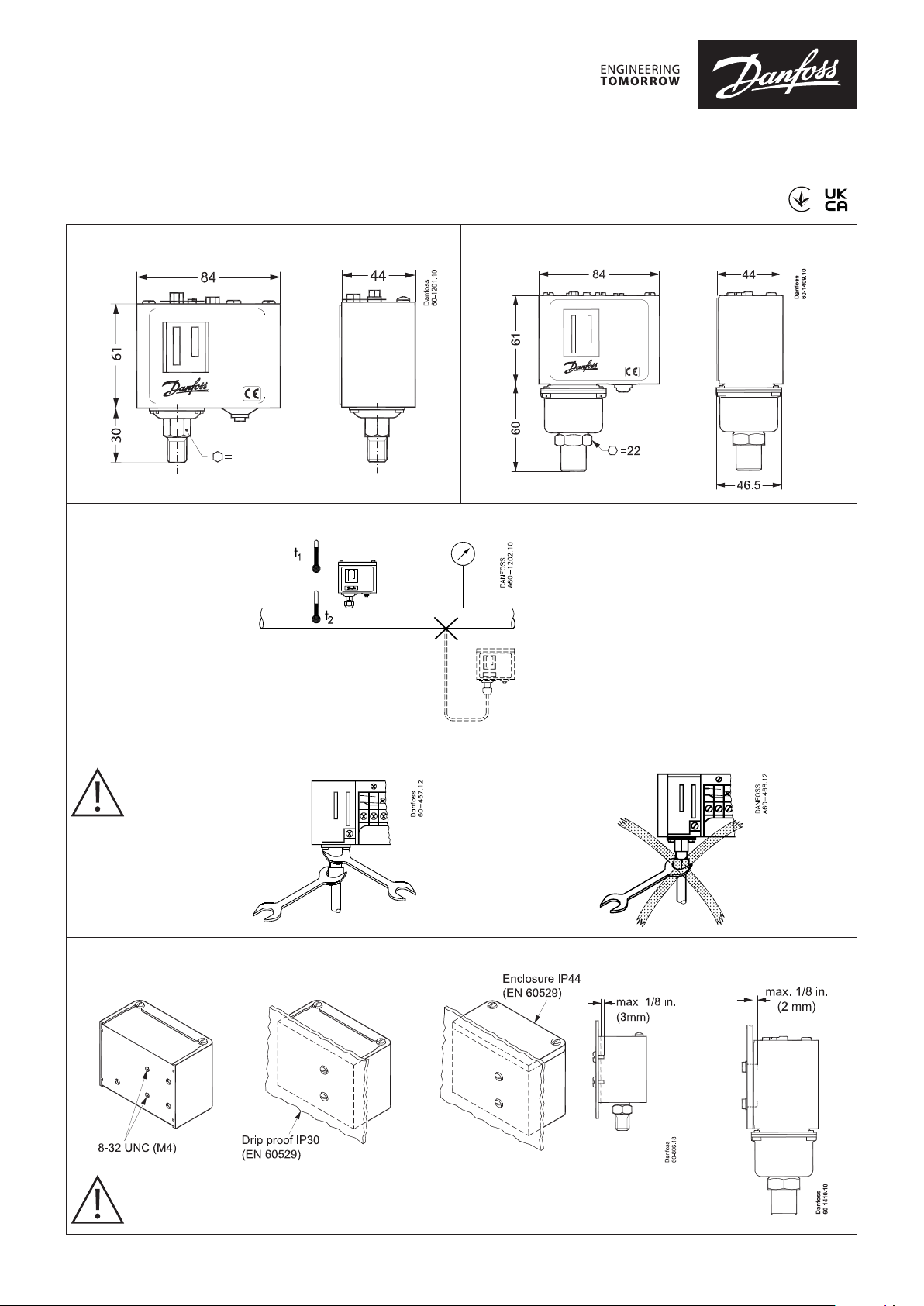
KP 35, KP 36, KP 37 KP 33, KP 34
060R9309
60-572.11
14 / 12 *)
*) KP 35 (060-604891)
KP 33, KP 34, KP 35, KP 36, KP 37
t1 min. -40 °C
t1 max. 65 °C
t2 min. -40 °C
t2 max. 100 °C
P
max.
test
KP 33: 10 bar
KP 34: 6 bar
KP 35: 22 bar (19 bar 060-604891)
KP 36: 22 bar
KP 37: 32 bar
060R9309
No maintenance is required for the switches after nal installation.
KP 35, KP 36, KP 37 KP 33, KP 34
CAUTION:
The mounting panel must be plane to avoid damage of switch.
Імпортер:ТОВ з іі "Данфосс ТОВ" 04080, Київ 80, п/с 168, Україна
© Danfoss | Climate Solutions | 2021.07 AN193186434341en-000602 | 1
Info for UK customers only: Danfoss Ltd., 22 Wycombe End, HP9 1NB, GB
Page 2
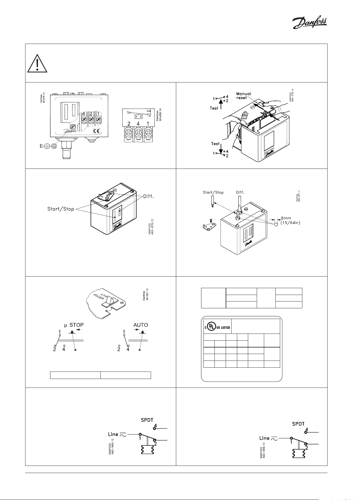
CAUTION:
Disconnect power supply before wiring connections are made or service to avoid possible electrical shock or damage to
equipment.
Do never touch live parts with your ngers or with any tool.
Please note: scale in KP units is indicative only. For accurate
setting or when using according to FM approval use additional
pressure gauge to set the unit.
KP 36 060-548766
Contact system with standard AG contacts.
Single pole changeover switch (SPDT).
Alternating current:
AC-1: 16 A, 400 V
AC-3: 16 A, 400 V
AC-15: 10 A, 400 V
Direct current:
DC-13: 12 W, 220 V
Electrical rating - General
AC 1: 16 A
LR 112A
When used acc. to UL or FM regulations
Voltage FL LR
AC DC A A
240 – 8 48 8 A
120 – 16 96 16 A
– 240 – – – 12 W
Use copper wire only
Tighten ing torque 20 lb. in.
AC 3: 16 A 12 W
AC 15: 10 A 220 V
Listed refrigeration
controller 61B5
400 V
Resist .
load
DC 13
Pilot
duty
3 A
Contact system with gold contacts.
Single pole changeover switch (SPDT): 1 – 30 mA, 5 – 30 V DC
Contact load when Au surface isburned away:
Alternating current:
AC-1: 10 A, 400 V
AC-3: 6 A, 400 V
AC-15: 4 A, 400 V
Direct current:
DC-13: 12 W, 220 V
© Danfoss | Climate Solutions | 2021.072 | AN193186434341en-000602
 Loading...