

Page 1
Data Sheet
Pressure switch
Type KP
The KP pressure switches can be used as safety
switches against too low a suction pressure
and / or too high a discharge pressure in
refrigeration and air conditioning systems. They
can also be used to start / stop compressors
and fans for air-cooled condensers.
They are available in both single and dual
versions and include a single pole double
throw (SPDT) switch.
Features:
• Ultra-short bounce time thanks to snapaction function (reduces wear to a minimum
and increases reliability)
• Available with gold-plated contacts
• SPDT switch design Oers open or close
switching action on pressure rise or fall
• Fail safe double bellows Prevent refrigerant
loss and system contamination - standard on
KP 7 and KP 17 pressure switches
• Convenient manual trip feature To test
electrical contact function - no tools needed
• Pressure wire connectors For easy electrical
wiring
• No spade or lug terminals required
• Integral 1⁄2 NPSM swivel cable connector
Allows direct attachment of 1⁄2 in male pipe
thread connector
• Lockplate Prevents tampering with range and
dierential settings
• Universal mounting hole patterns
AI216886432258en-001101
Page 2
421 4 2 1
Danfoss
A60-1032.10
A
B
C
D
E
F
G
H
I
I
ABCDEFGHI
SPDT - signal pole double throw
Pressure / Temperature
Rise
Drop
Load Cut-in (term.1-4)
Load Cut-out (term.1-2)
Load Cut-out (term.1-4)
Load Cut-in (term.1-2)
Line
Features
Values
Ambient temperature
-40 – 149 °F (175 °F for maximum 2 hours)
Maximum working pressure
LP: MWP = 245 psig
HP: MWP = 465 psig
Maximum test pressure
LP: pe = 285 psig
HP: pe = 510 psig
Switch
Single pole changeover switch (SPDT)
Contact load
120 V AC: 16 FLA, 96 LRA
240 V AC: 8 FLA, 48 LRA
240 V DC: 12 W pilot duty
Terminal D, dual switches
240 V, 50 VA
Control type
Material
KP 1, KP 2, KP 5, KP 7, KP 15, KP 17, KP 25
Tin bronze, no. CW452K, EN 1652 Nickel plated free cutting steel, no. 1.0737 /
1.0718 to EN 10277
KP with cap. tube
Copper SF-Cu, no. 2.0090 to DIN 1787
Load
Signal option
Bellows movement on pressure rise
Bellows movement on pressure drop
Pressure switch, Type KP
Product specication
Technical data
Table 1: Technical data
Cable entry
Integral 1⁄2 in female NPSM swivel cable connector allows direct attachment of 1⁄2 in male pipe thread connector.
Enclosure
~NEMA 1
This grade of enclosure is obtained when the units without top cover are mounted on a at surface or bracket.
The bracket must be xed to the unit so that all unused holes are covered.
~ NEMA 2
This grade of enclosure is obtained when the units with top cover are mounted on a at surface or bracket.
The bracket must be xed to the unit so that all unused holes are covered
Table 2: Materials in contact with the medium
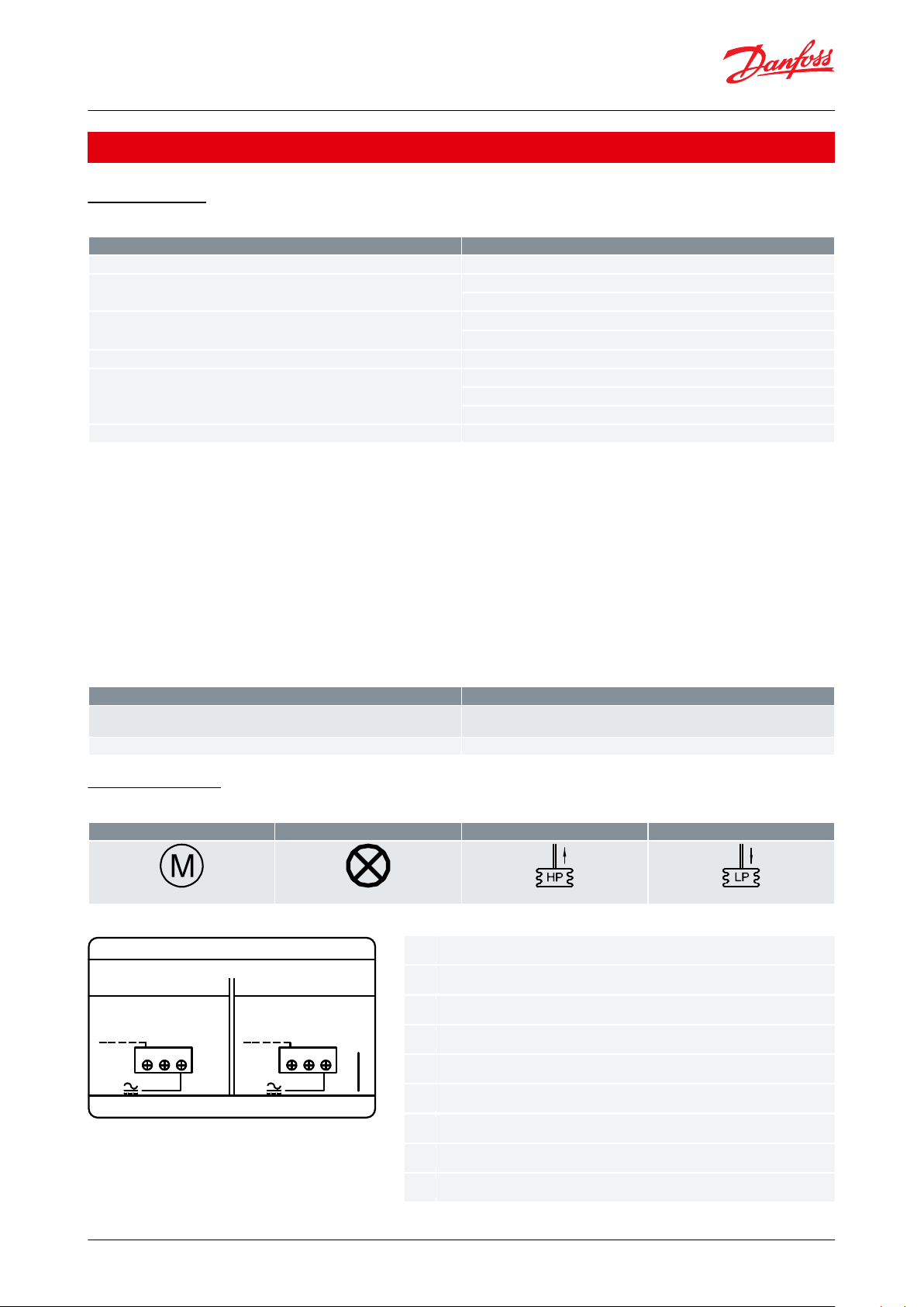
Electrical wiring
Table 3: Electrical wiring
Figure 1: Low or high pressure
© Danfoss | Climate Solutions | 2021.02 AI216886432258en-001101 | 2
Page 3
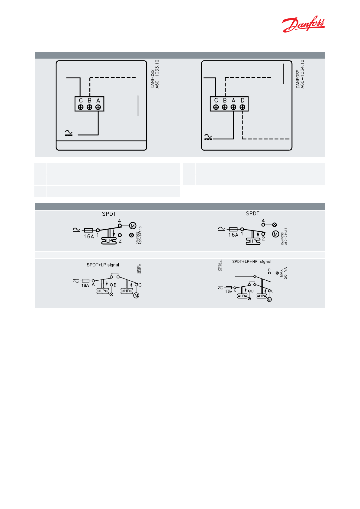
1.2.3.4.5.
Dual (low and high) pressure, LP signal
Dual (low and high) pressure, LP and HP signal
1
2
3
4
A2113
1
2
3 5
A2115
Load
LP - signal option
Line
Wiring instruction
HP - signal option
Low pressure, LP: KP 1 and KP 2
High pressure, HP: KP 5, KP 7W and KP 7B
Dual (low and high) pressure: KP 15, KP 17W, KP 17B and KP 25
Dual (low and high) pressure: KP 15, KP 17W, KP 17B and KP 25
Pressure switch, Type KP
Metric conversions
1 psi = 0.07 bar
5⁄9 (t1 °F - 32) = t2 °C
© Danfoss | Climate Solutions | 2021.02 AI216886432258en-001101 | 3
Page 4

1.2.3.5.7.8.9.
10.
11.
12.
13.
14.
15.
16.
18.
19.
30.
Pressure switch, type KP
KP 1, KP 2, KP 5
FW
FW
KP 15, KP 25 are
KP 1, KP 2, KP 5, KP 15, KP 25, KP 7W, KP 7B, KP 17W, capillary tube
FW
Low pressure setting spindle, (LP)
Dierential setting spindle
Main arm
High pressure setting spindle, (HP)
Main spring
Dierential spring
Bellows
LP connection
HP connection
Switch
Terminals
Earth terminal
Cable entry
Tumbler
Locking plate
Arm
Reset button
Pressure switch, Type KP
Design
Table 4: Design
The switch in the KP has a snap-action function where the bellows move only when the cut-in or cut-out value is
reached.
The bellows are connected to the low or high pressure side of the system through connection (10) or (11).
The design of the KP gives the following advantages:
• high contact load
• ultra-short bounce time
• high resistance to pulsation
• vibration resistance up to 4 g in the range 0 – 1000 Hz
• long mechanical and electrical life
© Danfoss | Climate Solutions | 2021.02 AI216886432258en-001101 | 4
Page 5

1.2.3.5.15.
18.
KP 7W (KP 7B), are
KP 7W (KP 7B), capillary tube
KP 17W (KP 17B), are
Pressure setting spindle, (LP)
Dierential setting spindle
Main arm
Pressure setting spindle, (HP)
Cable entry
Locking plate
Pressure switch, Type KP
The KP with designations W or B have been tested and approved by TÜV (Germany) in accordance with EN 12263.
Versions with designation W will cut in automatically when the pressure has fallen to the setpoint minus the
dierential.
Versions with designation B can be cut in manually using the external reset button when:
KP 1 – the pressure has increased to 10 psi above the setpoint.
KP 7 – the pressure has fallen 58 psi below the setpoint.
KP 7 and KP 17 are equipped with fail-safe double bellows; a regulation bellows and an outer bellows. The double
bellows system protects against loss of system charge in the event of a bellows rupture.
A rupture in the outer bellows will cause the control to trip approximately 43 psi lower than the actual control
setting. This features provides a warning without a loss of charge.
All KP pressure switches, including those which are PED-approved, operate independently of changes in the
ambient temperature around the control housing. Therefore the set cut-out pressure and dierential are kept
constant provided the permissible ambient temperatures are not exceeded.
Terminology
Reset
1.Manual reset: Units with manual reset can only be reset during operation by activation of the reset button.
2.Automatic reset: After operational stop, these units reset automatically.
Maximum working pressure
The Maximum working pressure is determined by the pressure that can be safely allowed in the refrigerating system
or any of the units within it. The maximum working pressure is designated MWP.
© Danfoss | Climate Solutions | 2021.02 AI216886432258en-001101 | 5
Page 6

KP 1, KP 2 and KP 5
Danfoss
60-760.13
KP 15 and KP 25
Danfoss
60-908.11
KP 7W and KP 7B
Danfoss
60-1014.12
KP 17W and KP 17B
Danfoss
60-1015.14
Pressure switch, Type KP
Test pressure
The test pressure is the pressure used in strength tests and / or leakage tests on refrigerating systems or individual
parts in systems. The test pressure is designated Pe.
“Snap function”
A certain contact force is maintained until irrevocable “snap” is initiated. The time during which the contact force
approaches zero is thus limited to a very few milliseconds. Therefore contact bounce cannot occur as a result of, for
example, slight vibrations, before the cut-out point. Contact systems with “Snap function” will change over even
when micro-welds are created between the contacts during cut-in. A very high force is created during cut-out to
separate the contacts. This force immediately shears o all the welds. Thus the cut-out point of the unit remains very
accurate and completely independent of the magnitude of the current load.
Setting
Pressure switches with automatic reset – LP: Set the LP start pressure on the “CUT-IN” scale (range scale). One
rotation of the low pressure spindle ~10 psi. Set the LP dierential on the “DIFF” scale. One rotation of the
dierential spindle ~ 3 psi. The LP cut-out pressure is the LP cut-in pressure minus the dierential.
NOTE:
The LP cut-out pressure must be above absolute vacuum pe = 30 in Hg. If compressor will not stop at low cut-out
pressure, check whether the dierential value is set at too high a value!
Metric conversions 1 psi = 0.07 bar
Pressure switches with automatic reset – HP: Set the HP cut-out pressure on the “CUT-OUT” scale. One rotation of
the HP spindle ~ 33 psi. Set the HP dierential on the “DIFF” scale.
One rotation of the dierential spindle ~ 4 psi. The HP cut-in pressure is the HP cut-out pressure minus the
dierential. Pressure switches with manual reset. Set the cut-out pressure on “CUT-OUT” scale (range scale). Low
pressure controls can be manually reset when the pressure is equal to the cut-out pressure plus the dierential.
High pressure switches can be manually reset when the pressure is equal to the cut-out pressure minus the
dierential.
Cut-in and cut-out pressures for both the LP and HP sides of the system should always be checked with an accurate
pressure gauge.
Dimensions [in] and weight [lb]
Table 5: Flare connection
© Danfoss | Climate Solutions | 2021.02 AI216886432258en-001101 | 6
Page 7

KP 1, KP 2, KP 5, KP 7W and KP 7B
Danfoss
60-950.13
KP 15, KP 17W, KP 17B and KP 25
Danfoss
60-991.14
Single switches
Danfoss
60-1023.14
Dual switches
Danfoss
60-1024.14
Wall bracket
Angle bracket
Danfoss
60-1011.13
Pressure switch, Type KP
Table 6: Capillary tube connection
Net weight:
KP 1, KP 2, KP 5 and KP 7:
approx. 0.7 lbs.
KP 15, KP 17 and KP 25:
approx. 1.1lbs.
Metric conversions:
1 in = 25.5 mm
1 lb = 0.454 kg
Table 7: KP switches, rear side
Table 8: Bracket dimensions
© Danfoss | Climate Solutions | 2021.02 AI216886432258en-001101 | 7
Page 8
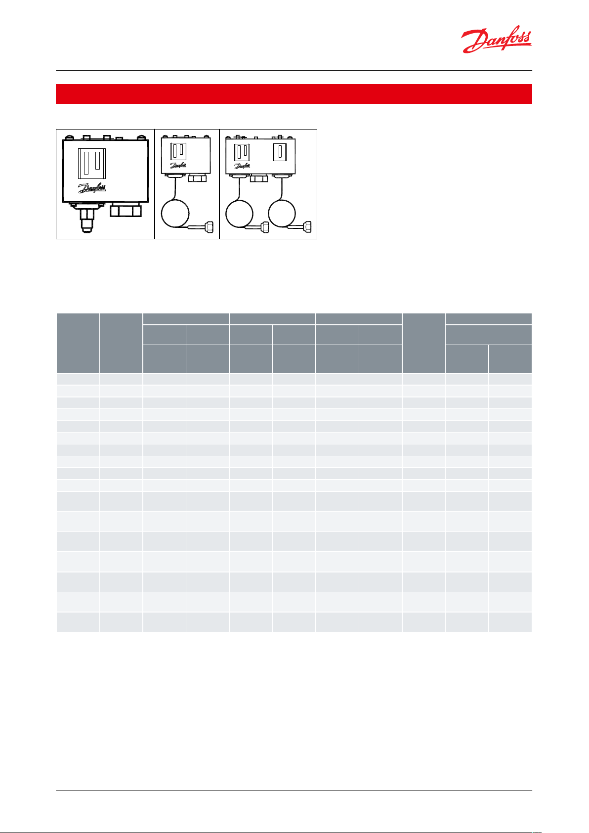
Type
Pressure
Low pressure (LP)
High pressure (HP)
Reset
Contact
functio
Code no.
Regulating
range
Dierential
∆p
Regulating
range
Dierential
∆p
Low pres‐
sure
High pres‐
sure
connection
[inHg] [psig]
[psi]
[psig]
[psi]
[LP]
[HP]
1⁄4 in are
Cap. tube w.
1⁄4 in are
nut 36 in
KP 1
Low
6 in – 108
10 – 58––
Auto–SPDT
060-200191
–
KP 1
Low
6 in – 108
10 – 58––
Auto–SPDT
–
060-205191
KP 1
Low
27 in – 10010––Man. (Min.)
–
SPDT
–
060-205291
(1)
KP 2
Low
6 in – 50
6 – 32––
Auto–SPDT
–
060-206391
KP 5
High––
115 – 465
25 – 85–Auto
SPDT
060-201491
–
KP 5
High––
115 – 465
25 – 85–Auto
SPDT
–
060-206491
KP 7W
(2)
High––
115 – 465
58 – 140–Auto
SPDT
060-200391
–
KP 7W
(2)
High––
115 – 465
58 – 140–Auto
SPDT
–
060-205391
KP7B
(2)
High––
115 – 46558–
Man. (Max.)
SPDT
060-200491
–
KP7B
(2)
High––
115 – 46558–
Man. (Max.)
SPDT
–
060-205491
KP 15
Dual
6 in – 108
10 – 58
115 – 465
58
Auto
Auto
SPDT/w. L P
signal
060-200891
–
KP 15
Dual
6 in – 108
10 – 58
115 – 465
58
Auto
Auto
SPDT/w. L P
signal
–
060-205891
KP 15
Dual
6 in – 108
10 – 58
115 – 465
58
Auto
Man. (Max.)
SPDT/w. L P
signal
–
060-205991
KP 15
Dual
6 in – 108
10 – 58
115 – 465
58
Man. (Min.)
Man. (Max.)
SPDT/w. L P
signal
–
060-206091
KP 15
Dual
6 in – 108
10 – 58
115 – 465
58
Auto
Auto
SPDT/w. LP +
HP signal
–
060-203191
KP 15
Dual
6 in – 108
10 – 58
115 – 465
58
Auto
Man. (Max.)
SPDT/w. LP +
HP signal
060-202691
–
KP 17W
(2)
Dual
6 in – 108
10 – 58
115 – 465
58
Auto
Auto
SPDT/w. LP +
HP signal
–
060-202991
Pressure switch, Type KP
Ordering
Figure 2: Ordering
For R22, R134a, R404A, R407A, R407C, R407F, R422B, R422D, R448A, R449A, R450A, R452A, R507A, R513A
For complete list of approved refrigerants, visit www.products.danfoss.com and search for individual code numbers,
where refrigerants are listed as part of technical data.
Table 9: Ordering
(1)
(1)
With dial knob
With dial knob
(2)
(2)
With fail safe double bellows
With fail safe double bellows
Metric conversions
1 psi = 0.07 bar
5⁄9 (t1 °F - 32) = t2 °C
© Danfoss | Climate Solutions | 2021.02 AI216886432258en-001101 | 8
Page 9

Document type
Approval authority
UL certicate
UL
EAC document
EAC
EU declaration
Danfoss
CCC declaration
Danfposs
Quality - Assurance Certicate
TUV
Marine safety certicate
DNV G L ,LR and BV
Manufacturer declaration for China ROHS
Danfoss
Pressure switch, Type KP
Certicates, declarations, and approvals
The list contains all certicates, declarations, and approvals for this product type. Individual code number may have
some or all of these approvals, and certain local approvals may not appear on the list.
Some approvals may change over time. You can check the most current status at danfoss.com or contact your local
Danfoss representative if you have any questions.
Table 10: Certicates, declarations, and approvals
© Danfoss | Climate Solutions | 2021.02 AI216886432258en-001101 | 9
Page 10
Online support
Danfoss oers a wide range of support along with our products, including digital product information, software,
mobile apps, and expert guidance. See the possibilities below.
The Danfoss Product Store
The Danfoss Product Store is your one-stop shop for everything product related—no matter where
you are in the world or what area of the cooling industry you work in. Get quick access to essential
information like product specs, code numbers, technical documentation, certications, accessories,
and more.
Start browsing at store.danfoss.com.
Find technical documentation
Find the technical documentation you need to get your project up and running. Get direct access to
our ocial collection of data sheets, certicates and declarations, manuals and guides, 3D models
and drawings, case stories, brochures, and much more.
Start searching now at www.danfoss.com/en/service-and-support/documentation.
Danfoss Learning
Danfoss Learning is a free online learning platform. It features courses and materials specically
designed to help engineers, installers, service technicians, and wholesalers better understand the
products, applications, industry topics, and trends that will help you do your job better.
Create your Danfoss Learning account for free at www.danfoss.com/en/service-and-support/learning.
Get local information and support
Local Danfoss websites are the main sources for help and information about our company and
products. Find product availability, get the latest regional news, or connect with a nearby expert—all
in your own language.
Find your local Danfoss website here: www.danfoss.com/en/choose-region.
Coolselector®2 - nd the best components for you HVAC/R system
Coolselector®2 makes it easy for engineers, consultants, and designers to nd and order the best
components for refrigeration and air conditioning systems. Run calculations based on your operating
conditions and then choose the best setup for your system design.
Download Coolselector®2 for free at coolselector.danfoss.com.
Danfoss can accept no responsibility for possible errors in catalogues, brochures and other printed material. Danfoss reserves the right to alter its
products without notice. This also applies to products already on order provided that such alterations can be made without subsequential
changes being necessary in specications already agreed. All trademarks in this material are property of the respective companies. Danfoss and
the Danfoss logotype are trademarks of Danfoss A/S. All rights reserved.
© Danfoss | Climate Solutions | 2021.02 AI216886432258en-001101 | 10
 Loading...