

Installation guide
Pressure switch
Type KP 21
© Danfoss A/S (AC-MCI / jmn), 2013-11 IC.PI.P10.G3.02 / 520B5881 1
060R9410
060R9410
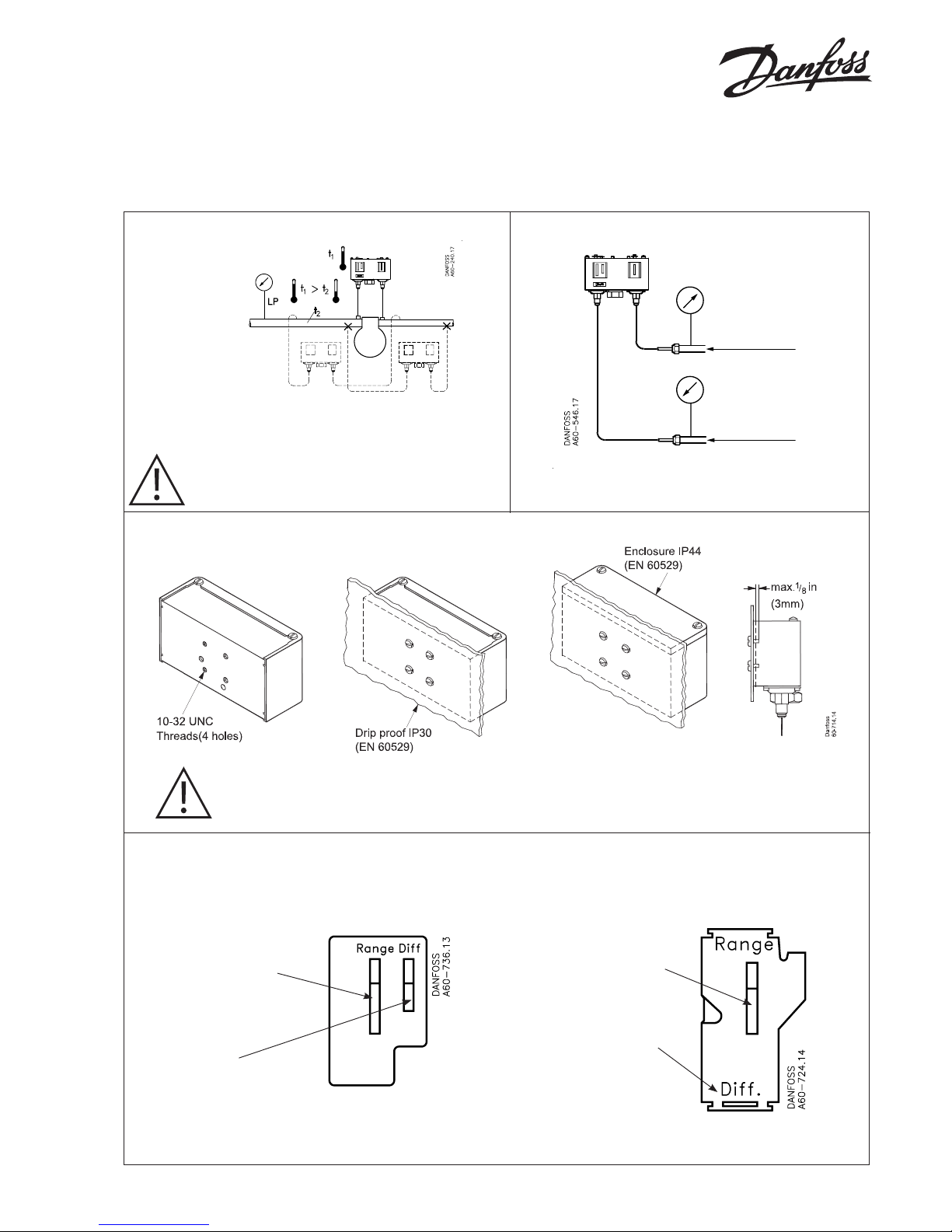
Ambient temperatures
Caution: Do not mount a switch in a position where
dirt, sediment or oil will aect the operation of the switch.
Enclosure
CAUTION: The mounting panel must be plane to avoid damage of switch.
Low pressure (LP) side setting
CUT-IN minus DIFFERENTIAL equals CUT-OUT
Test pressure (p
test
)
High pressure (HP) side setting
CUT-OUT minus DIFFERENTIAL equals CUT-IN
P
test
max.
20 bar P
e
P
test
max.
20 bar P
e
LP
HP
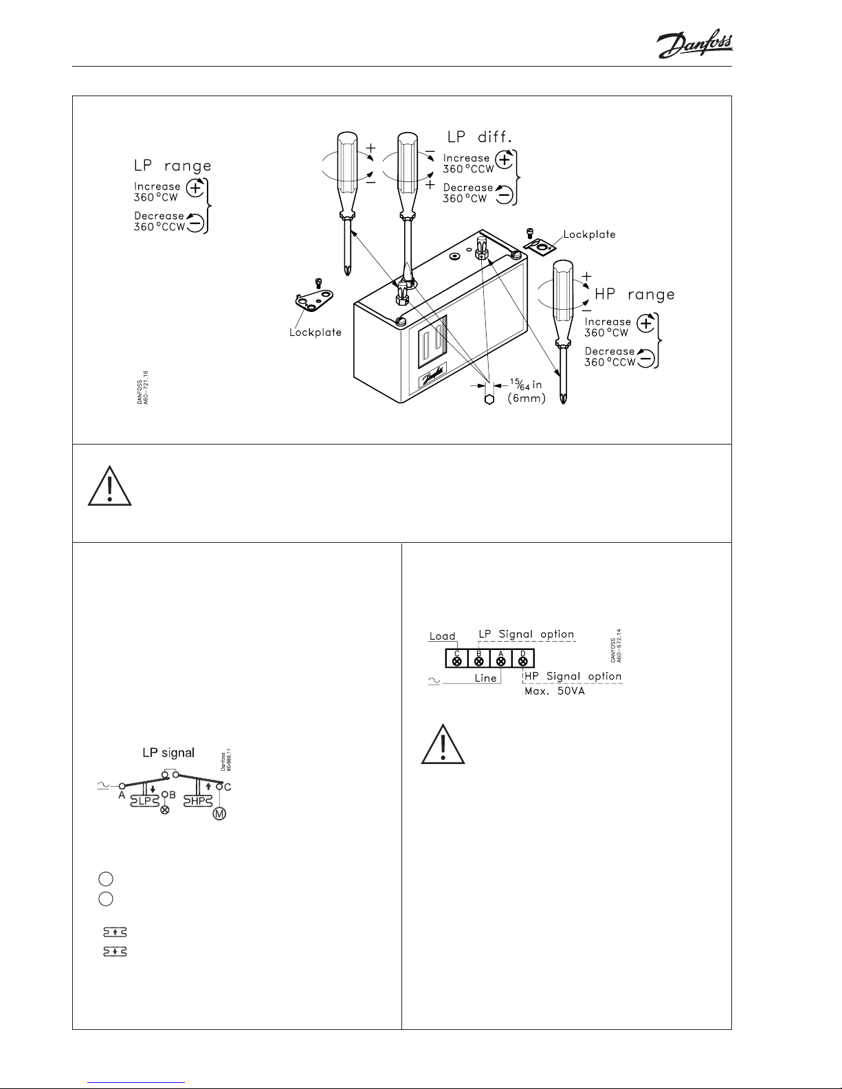
1. Adjust range spindle to
desired CUT-IN value
2. Adjust dierential
spindle to desired
DIFFERENTIAL
(DIFF.) value
LP
scale
1. Adjust range spindle to
desired CUT-OUT value.
2. DIFFERENTIAL (DIFF.)
is xed.
Value printed on scale plate.
tl min. −40°C (−40°F)
−25ºC (−13ºF)
tl max 65ºC (150ºF)
HP
scale
2 IC.PI.P10.G3.02 / 520B5881 © Danfoss A/S (AC-MCI / jmn), 2013-11
CAUTION:
Disconnect power supply before wiring connections are made or service to avoid possible electrical shock or damage
to equipment.
Do never touch live parts with your ngers or with any tool.
Controls with low pressure (LP) and
high pressure (HP) signal
Terminal block
Contact load
Alternating current:
AC 1: 16 A, 400 V
AC 3: 16 A, 400 V
AC15: 10 A, 400 V
Max. starting current (L.R.): 112 A, 400 V
Direct current:
DC13: 12 W, 220 V control current
Function
Note!
= Load
= Signal option
= Bellows movement on pressure rise
= Bellows movement on pressure drop
CAUTION: Use terminal screws furnished
in the contact block.
Use tightening torque (20 lb.) in 2.3 Nm.
Use copper wire only.
Low pressure (LP) side:
A-C close on LP rise
A-C open on LP drop
High pressure (HP) side.
A-C open on HP rise
A-C close on HP drop
LP signal option:
A-B close on LP drop
HP signal option
A-D close on HP rise
M
X
 Loading...