

Page 1
Data sheet
Pressure switch
Type KP-E
KP-E pressure switches for use in refrigeration
and air conditioning systems are equipped with
SPDT gold plated contacts and stainless steel
bellows.
The high pressure switches are equipped with
failsafe double bellows, whereas the low pressure
switches are equipped with reduced bellow
travel to enhance bellows life time.
KP-E pressure switches are used to protect
against excessively low suction pressure or
excessively high discharge pressure.
The units are designed to operate in explosive
zones acc. to 2014/34/EU, Atex directive,
explosive zone 2, surface equipment, category 3.
KP-E pressure switches for HCFC, HFC and HC
refrigerants are equipped with ¼ in solder
connection to ensure a hermetic installation.
Features • Ultra-short bounce time thanks to snap-action
function (reduces wear to a minimum
and increases reliability)
• Manual trip function
(electrical contact function can be
tested without the use of tools)
• Vibration and shock resistant
Approvals
CE-marked in accordance with EN 60947-4/-5
(for sale in Europe)
CE marked in accordance with PED 2014/68/EU,
category IV, safety equipment
• Compact design
• Bellows without any welding points
• Stainless steel bellows
• High reliability both electrically and
mechanically
Ex II 3G Ex ic IIB T6 Gc in accordance with
2014/34/EU Atex directive
© Danfoss | DCS (rm) | 2019.11
DKRCC.PD.CD0.1B.02 | 1
Page 2
Data sheet | Pressure switch, type KP-E
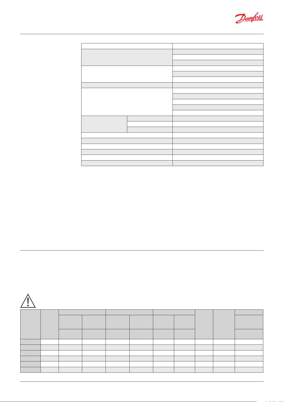
Technical data
Ambient temperature -20 – 60 °C
KP 1E: PS / MWP = 17.0 bar *
Max. working pressure
Max. test pressure
Cable connection Pg 13.5 screwed cable entry for 6 – 14 mm cable
Contact rating
solid / stranded 0.75 – 2.5 mm
Wire dimensions
Tightning torque max. 2 Nm
Rated impulse voltage 4 kV
Pollution degree 3
Short circuit protection, fuse 10 A
Insulation 400 V
Enclosure IP30 / IP44
*
Low pressure protection
flexible, without ferrules 0.7 – 2.5 mm
flexible, with ferrules 0.7 – 2.5 mm
KP 6EW, KP 6EB: PS / MWP = 46.5 bar
KP 7EW, KP 7EB: PS / MWP = 32 bar
KP 1E: Pe = 20 bar
KP 6EW, KP 6EB: Pe = 46.5 bar
KP 7EW, KP 7EB: Pe = 35 bar
Pi max: 1 W
Ui max: 30 V
Ii max: 0.1 A
Ci max: 0.5 nF
Li max: 0.2 H
2
2
2
Enclosure
IP30 to EN 60529 / IEC 529
Enclosure IP30 is obtained when the units
without top cover are mounted on a flat surface
or bracket. The bracket must be fixed to the unit
so that all unused holes are covered.
IP44 to EN 60529 / IEC 529
Enclosure IP44 is obtained when the units with
top cover are mounted on a flat surface or
bracket. The bracket must be fixed to the unit so
that all unused holes are covered. KP pressure
switches with auto reset are supplied with top
cover. For KP pressure switches with manual
reset, the top cover must be separately ordered
(code no. 060-109766)
Ordering
FOR R290, R32, R444B, R600, R600a, R1234ze, R1270
For complete list of approved refrigerants, visit www.products.danfoss.com and search for individual code numbers, where refrigerants are
listed as part of technical data.
This product is validated in accordance to EN 60079-0:2012 + A11:2013.
Ignition risk is evaluated in accordance to EN 60079-11:2012.
See safety requirements on the next page.
Low pressure (LP) High pressure (HP) Reset
Typ e Pressure
KP 1E Low - 0.2 – 7.5 0.7 – 4.0 – – Auto – SPDT PSL 060-530066
KP 1E Low - 0.9 – 7.0 0.7 – – Man. (Min.) – SPDT PZL 060-530266
KP 6EW High – – 8 – 42 4 – 10 – Auto SPDT PSH 060-522466
KP 6EB High – – 8 – 42 4 –
KP 7EW High – – 8 – 32 4 – 10 – Auto SPDT PSH 060-530466
KP 7EB High – – 8 – 32 4 –
*
PSL, PZL, PSH, PZH according to EN 12263:1998
Regulating
range
[bar] [bar] [bar] [bar]
Differential pRegulating
range
Differential
p
Low
pressure
LP
High
pressure
HP
Man. (Max.)
Man. (Max.)
Contact
system
SPDT PZH 060-522566
SPDT PZH 060-530666
Function *
Code no.
Connection
1
/4 in. ODF
solder
© Danfoss | DCS (rm) | 2019.11
DKRCC.PD.CD0.1B.02 | 2
Page 3

Danfoss
60-8070.11
Data sheet | Pressure switch, type KP-E
Safety requirements The KP-E can be applied on systems
with R290, R32, R444B, R600, R600a,
R1234ze, R1270 as the working fluid.
For countries where safety standards are not an
indispensable part of the safety system Danfoss
recommend the installer to get a third party
approval of the system containing flammable
refrigerant.
Note, please follow specific selection criteria
stated in the datasheet for these particular
refrigerants.
KP-E pressure switches comply with the
requirements for explosive atmosphere
2014/34/EU,
acc. to ATEX, zone 2.
Only apparatus designed, constructed and
released by Danfoss must be used for application
concerned. Danfoss can accept no responsibility
in case of alterations made on the switches or
the use of them against the Danfoss instructions.
Original Danfoss spare parts approved for use in
explosive atmosphere can only be used.
The application covers systems that must be
located within the EU or EFTA and comply with
the existing EU legislation, such as Pressure
Equipment Directive (PED) 2014/68/EU, the
directive concerning potential explosive
atmosphere (ATEX) 2014/34/EU, and other
related EU standards. The system where KPE is
mounted must always comply with local
directives, legislation or any other regulation
applying in the area of installation. The Danfoss
products comply with the requirements of ATEX
directive, but Danfoss takes no responsibility for
the classification of explosive zone.
Electrical connection
Intrinsic safety protection
method
The KP-E pressure switch placed in explosive
zone must always be wired through reliable Ex
zener barrier, placed outside ex-zone, to ensure
insufficient energy supply to cause the ignition
of surrounding atmosphere by an electrical spark
or the heating of components of circuitry.
The equipment to be used for electrical load
limiting must always be approved for use
in the zone concerned.
EX - zone Non EX - zone
KP-E
Cables and cable entries approved for the
application must be used and can not be in
contact with sharp edges. Cables must be
connected with adequate stress relief that way
that pulling forces can not be carried throug
the cable to the terminal.
Note:
A particular system can be classified in different
zones, for different parts of the system.
Electrical data for intrinsically safe
specification (for all KP-E types):
Pi max: 1 W
Ui max: 30 V
Ii max: 0.1 A
EX certified
Zenner barrier
Must be used with certified Ex ic barrier (product matching) satisfying the input parameters
Ci max: 0.5 nF
Li max: 0.2 µH
Signal
© Danfoss | DCS (rm) | 2019.11
DKRCC.PD.CD0.1B.02 | 3
Page 4

Data sheet | Pressure switch, type KP-E
Installation
and maintenance
Design / Function
Only authorised persons, who are certified in
installing and maintaining the systems may do
the installation, maintenance and change of the
switch.
In the event of strong pulsation in the system,
bellows must be protected against fatigue failure
by use of damping coil.
KP 1E KP 6EW, KP 7EW
The cycle frequency of the KP-E switch must be
kept as low as possible. The vibration level must
be kept as low as possible.
Any overload of the KP-E switch must be
prevented. Overloaded or damaged apparatus
must be exchanged.
1. Pressure setting spindle
2. Differential setting spindle
3. Main arm
4. Cable entry
5. Locking plate
6. Bellows travel reducer
(only KP 1E)
The switch in the KP-E has a snap-action function
when the cut-in or cut-out value is reached.
The design of the KP-E affords the following
advantages:
y ultra-short bounce time
y vibration resistance up to 4 g
in the range 0 – 1000 Hz
y long mechanical and electrical life
The KP 1E, KP 6EW, KP 6EB, KP 7EW and KP 7EB
switches have been tested and approved by TÜV
(Germany) in accordance with Directive
2014/68/EU.
KP 6E and KP 7E have a double bellows: an outer
bellows and a regulating bellows. When system
pressure exceeds the set value, the KP-E will
automatically stop the plant. The double bellows
system prevents loss of charge in the event of
bellows rupture.
A rupture in the outer bellows will cause the
control cut-out pressure to fall to about 3 bar
under the set value, thus providing a fail-safe
function.
Versions with designation W cut in again
automatically when the pressure has fallen
to the set value minus the differential.
Verions with designation B can be cut in
manually with the external reset button when
the pressure has fallen 4 bar under the set value.
© Danfoss | DCS (rm) | 2019.11
DKRCC.PD.CD0.1B.02 | 4
Page 5

Setting
Pressure switches with automatic reset – LP:
Set the LP start pressure on the “CUT-IN”
scale (range scale).
One rotation of the low pressure
spindle ~ 0.7 bar.
Set the LP differential on the “DIFF” scale.
One rotation of the differential spindle ~ 0.15 bar.
The LP stop pressure is the LP start pressure
minus the differential.
Pressure switches with automatic reset – HP:
Set the HP pressure on the “CUT-OUT” scale.
One rotation of the HP spindle ~ 2.3 bar.
Set the HP differential on the “DIF” scale.
One rotation of the differential spindle ~ 0.3 bar.
The HP start pressure is the HP stop pressure
minus the differential.
Pressure switches with manual reset:
Set the stop pressure on “CUT-OUT”
scale (range scale).
Low pressure switches can be manually reset
when the pressure is equal to the stop pressure
plus the differential.
Note:
The LP stop pressure must be above absolute
vacuum (Pe = -1 bar)!
If with low stop pressure the refrigeration
compressor will not stop, check to ensure that
the differential value has not been set too high!
Start and stop pressures for both the LP and HP
sides of the system should always be checked
with an accurate pressure gauge.
High pressure switches can be manually reset
when the pressure is equal to the stop pressure
minus the differential.
and weight [kg]
Solder connection, types KP 1E, KP 6EW, KP 6EB, KP 7EW, KP 7EBDimensions [mm]
84
61
114
Net weight: approx. 0.3 kg
44
© Danfoss | DCS (rm) | 2019.11
DKRCC.PD.CD0.1B.02 | 5
 Loading...