

Page 1
Installation guide
Pressure switch, KP 1, KP 1W, KP 1A, KP 2, KP 5, KP 5A, KP6W, KP 6B,
KP 6S, KP 6AW, KP 6AB, KP 6AS, KP 7W, KP 7B, KP 7S
Refrigerants:
R22, R134a, R404A, R407A, R407C, R407F, R410A*) R422B, R422D,
060R9750
R448A, R449A, R452A, R507A, R513A, R717**)
For complete list of approved refrigerants, go to
http://products.danfoss.com/all-products/
*) only for KP 6W, KP 6B, KP 6S, KP 6AW, KP 6AB, KP 6AS
**) only for KP 1A, KP 5A, KP 6AW, KP 6AB, KP6 AS
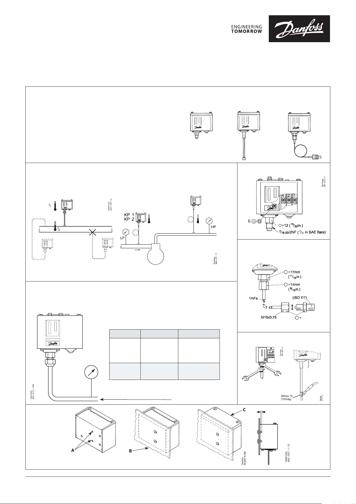
Ambient temperatures / Mounting requirements
-40 – 65 °C
-25 – 65 °C (PED approved units)
KP 5, KP 6, KP 7
KP 1, KP 2,
KP 5, KP 6, KP 7
KP 1, KP 2,
KP 5, KP 6, KP 7 KP 1A, KP 5A
Connections
Connections
for KP 1A, KP 5A, KP 6AS
060R9750
Relative humidity RH: 30 – 98%
Vibrations resistance: 4 g (10 – 1000 Hz)
Test pressure (P
PS/MWP
test
)
P
test
KP 1, KP 2: 20 bar pe (285 psig)
KP 2: 12 bar pe (174 psig)
KP 5, KP 7: 35 bar pe (510 psig)
KP 6: 46,5 bar pe (675 psig)
Typ e Regulation range PS/MWP
KP 1
KP 1, reset
KP 1 W
KP 2
KP 2
KP 5
KP 6
KP 7
PS/MWP
(Maximum Working Pressure)
Enclosure
max.:
-0.2 – 7.5 bar
-0.9 – 7.0 bar
0.5 – 3.0 bar
-0.2 – 5. 0 bar
-0.2 – 3.5 bar
8 – 32 bar
8 – 42 bar
8 – 32 bar
245 psig / 17 bar
245 psig / 17 bar
245 psig / 17 bar
245 psig / 17 bar
145 psig / 10 bar
510 psig / 35 bar
675 psig / 46,5 ba r
510 psig / 35 bar
Mounting
max. 3 mm (1/8 in.)
R ¼
14 mm
(9/16 in.)
Max. 100 ºC
(212 ºF)
A: 8 – 32 UNC (M4)
B: Enclosure IP30
© Danfoss | Climate Solutions | 2021.05
(EN 60529)
C: Enclosure IP44
(EN 60529)
AN211886 440281en-000701 | 1
Page 2
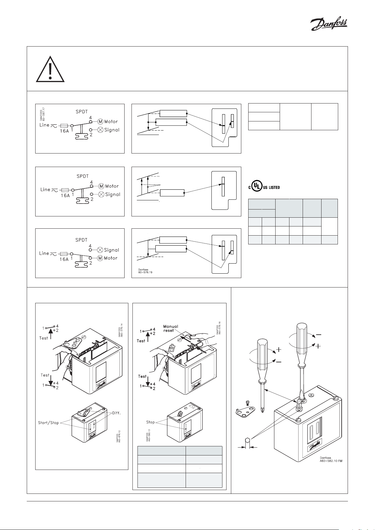
CAUTION:
Disconnect power supply before wiring connections are made or service to avoid possible electrical shock
or damage to equipment. Do never touch live parts with your ngers or with any tool.
Contact 1-4 opens on pressure drop
Contact 1-4 opens on pressure drop
Contact 1-2 opens on pressure rise
KP 1, KP 2
Cut In
Dierential
Cut Out
-1 bare (30 in. Hg)
KP 1W, KP 1 manual reset
Cut In
Dierential xed
Cut Out
-1 bare (30 in. Hg)
KP 1W: 0.5 bare
KP 5, KP 5A, KP 6, KP 6A, KP 7
Cut Out
Dierential
Cut In
AC 1: 16 A
AC 3: 16 A
AC 15: 10 A
400 V a.c.
DC 13
12 W
220 V
Short circuit protection:
Fuse 16 Amp.
When used acc. to UL regulations
Listed refrigeration
controller 61B5
Voltage FL LR
AC DC A A
240 — 8 48 8 A
120 — 16 96 16 A
— 240 — — — 12 W
Resist.
load
Use copper wire only
Tightening torque 20 lb. in.
Pilot
duty
3A
Manual trip function
Automatic reset
Note:
use FINGERS ONLY!
(Do NOT use screwdriver)
Manual reset
Typ e Dierential
KP 1, KP 1A 0.7 bar (10 psi)
KP 5, KP 5A 3 bar (43 psi)
KP 6B, KP 6S, K P 6AB,
KP 6AS, KP 7B, KP 7S
4 bar (58 psi)
Adjustment
Dierential
Range
6 mm
(15/64 in.)
© Danfoss | Climate Solutions | 2021.05
AN211886 440281en-000701 | 2
Page 3

CAUTION:
Only for selected A2L refrigerants: R455A, R454C, R1234yf, R1234yz, R1234ze
For complete list of approved A2L refrigerants, go to http://products.danfoss.com/all-products/
Electrical rating
AC-3: 16 A / 250 V AC
AC-15: 10 A / 250 V AC
Voltage Current range
Power factor
(cos phi)
Frequency
250V AC ≤ 4.0 A PF ≥ 0,400 50Hz/60Hz
250V AC > 4.0 to 6.0 A PF ≥ 0,594 50Hz/60Hz
250V AC > 6.0 to 16,0 A PF ≥ 0,780 50Hz/60Hz
IMPORTANT NOTICE
Safety requirements
1. KP pressure switches shall only be employed in the units/systems which comply with the requirements for charge limits and
requirements for avoiding ignition sources of IEC 60335-2-24, IEC 60335-2-40, IEC 60335-2-89, ISO 5149, EN378-1 or equivalent.
2. Applying the overload on the KPs must be prevented. If by any chance it was damaged, the system / unit shall be stopped and
KP shall be replaced as necessary.
3. Electrostatic discharge protection and Electrical leakage protection shall be surely implemented by grounding or other
measures.
4. Only trained personnel are authorized to handle ammable refrigerants systems and may do the installation, maintenance and
exchange of the switch by using appropriate tools.
5. It is recommended to regularly check the function of KP switch.
6. The KP pressure switches shall be used as built-in devices that cannot be accessible from outside and protected against
mechanical impact.
7. The KPs shall be installed in water free environment. In addition, protection of the KP switches against corrosion shall be taken
into consideration when using them in corrosive environment.
8. Cables shall not be in contact with sharp edges. The cables shall be connected with adequate stress relieve in order to prevent
that pulling forces can be carried thorough the cable to the terminal.
9. In the event of pressure pulsation in the system, where switch is connected, these must be eectively dumped to prevent
failure of the bellows. The cycle frequency of KP switch shall be kept as low as possible.
10. The KP switches shall not be installed in places where high level of vibration is present.
Disclaimer
The user is responsible for ensuring that third parties also comply with this Notice, e.g. in case that the KP switches are supplied to
third parties, and e.g. that all installation guides are available with the KP switches during installation. It is required that all
conditions of this guide are being met and secured when using KP pressure switches.
Danfoss shall not be responsible for any kind of direct and indirect or consequential damage or loss, including, but not limited to,
loss of property, production, loss of prot, human injury arising out of the explosion or re caused by the ammable nature of
refrigerant.
© Danfoss | Climate Solutions | 2021.05
AN211886 440281en-000701 | 3
 Loading...