

Page 1
Data Sheet
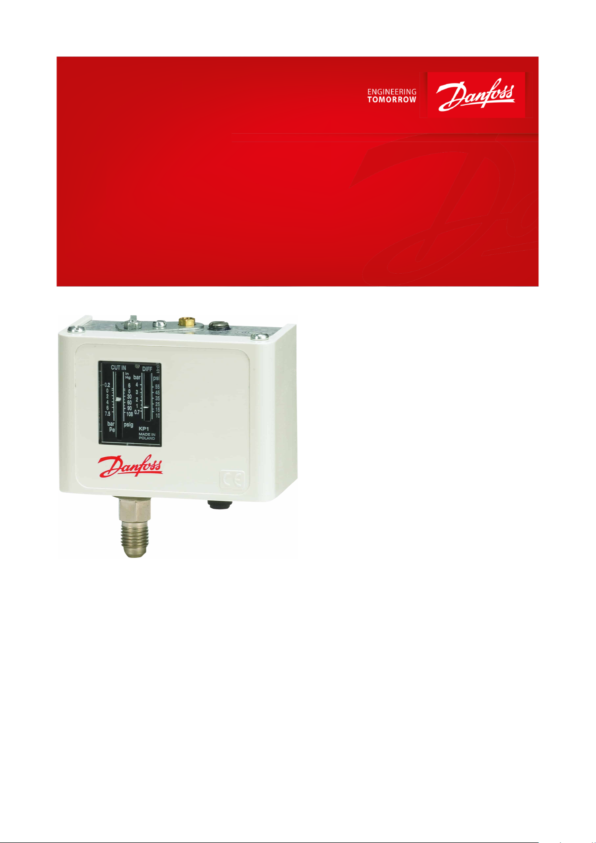
Pressure switch
Type KP
KP pressure switchs are for use in refrigeration
and air conditioning systems to give protection
against excessively low suction pressure or
excessively high discharge pressure.
KP pressure switches are also used for starting
and stopping refrigeration compressors and
fans on air-cooled condensers.
A KP pressure switch can be connected directly
to a single-phase AC motor of up to approx. 2
kW or installed in the control circuit of DC
motors and large AC motors.
KP pressure switches are tted with a singlepole double-throw (SPDT) switch. The position
of the switch is determined by the pressure
switch setting and the pressure at the
connector. KP pressure switches are available in
IP30, IP44 and IP55 enclosures.
Features:
• Ultra-short bounce time thanks to snapaction function (reduces wear to a minimum
and increases reliability)
• Manual trip function (electrical contact
function can be tested without the use of
tools)
• Types KP 6, KP 7 and KP 17 with fail-safe
double bellows element
• Vibration and shock resistant
• Compact design
• Fully welded bellows element
• High reliability both electrically
and mechanically
AI213186439478en-001201
Page 2
Features
Values
Ambient temperature
-40 – 65 °C (80 °C for max. 2 hours)
Ambient temperature (PED approved units)
-25 – 65 °C (80 °C for max. 2 hours)
Media temperature
(1)
-50 – 100 °C
Max. working pressure
LP: PS / MWP = 17 bar
HP: PS / MWP = 35 bar
KP 6: PS / MWP = 46.5 bar
Max. test pressure
LP: Pe = 20 bar
HP: Pe = 35 bar
KP 6: Pe = 46.5 bar
Contact load
Alternating current
AC1 =16 A, 400 V
AC3 = 16 A, 400 V
AC15 = 10 A, 400 V
Direct current
DC13 = 12 W, 220 V control current
Wire dimensions
solid / stranded
0.75 – 2.5 mm
2
exible, without ferrules
0.7 – 2.5 mm
2
exible, with ferrules
0.5 – 1.5 mm
2
Tightening torque
max. 2 Nm
Rated impulse voltage
4 kV
Pollution degree
3
Short circuit protection, fuse
16 A
Insulation
400 V
Enclosure
IP30 / IP44 / IP55
Pressure switch, Type KP
Product specication
Technical data
Table 1: Technical data
(1)
(1)
The media temperature can be out of ambient temperature range under necessary condition that temperature inside KP must be kept in
The media temperature can be out of ambient temperature range under necessary condition that temperature inside KP must be kept in
ambient temperature range.
ambient temperature range.
Cable connection
The cable entry can be used for 6 – 14 mm dia. cables. A Pg 13.5 screwed cable entry can also be used for 6 – 14 mm
cable.With 8 – 16 mm cable a standard Pg 16 screwed cable entry can be used.
Enclosure
IP30 to EN 60529 / IEC 60529
Enclosure IP30 is obtained when the units without top cover are mounted on a at surface or bracket. The bracket
must be xed to the unit so that all unused holes are covered.
IP44 to EN 60529 / IEC 60529
Enclosure IP44 is obtained when the units with top cover are mounted on a at surface or bracket. The bracket must
be xed to the unit so that all unused holes are covered.
KP pressure switches with auto reset are supplied with top cover. For KP pressure switches with manual reset, the
top cover must be separately ordered (code no. 060-109766 for single pressure switches and code no.
060-109866 for dual pressure switches).
IP55 to EN 60529 / IEC 60529
IP55 is obtained when the KP pressure switches are mounted in an IP55 enclosure, (code no. 060-033066 for single
pressure switches and code no. 060-035066 for dual pressure switches). IP55 enclosure has to be ordered
separately.
© Danfoss | Climate Solutions | 2021.10 AI213186439478en-001201 | 2
Page 3

Low pressure (LP)
High pressure (HP)
Dual pressure (LP/HP)
Dual pressure (LP/HP)
Dual pressure (HP/HP)
Type
Material
KP 1, KP 2, KP 5, KP 6, KP 7, KP 15 and KP 17
Tinbronze, no. CW452K, EN 1652
Nickel plated free cutting steel, no. 1.0737 / 1.0718, EN 10277
KP 1A, KP 5A, KP 6A, KP 7A and KP 15A only
Stainless steel 18/8, no. 1.4306, EN 10088-2
Free cutting steel, no. 1.0737, EN 10277
Cold forming steel, no. 1.0338, EN 10139
Steel, no 1.0308, EN 10305
Free cutting steel, no. 1.0715, EN10277
Free cutting steel, no. 1.0718, EN 10277
Aluminium, no. AW-3005, EN 573
Pressure switch, Type KP
Contact systems
Table 2: Low and high pressure
Table 3: Dual pressure
Materials in contact with the medium
Table 4: Materials in contact with the medium
Terminology
Reset
1.
Manual (Min. / Max.) reset:
Units with manual reset can only be reset during operation by activation of the reset button.
2.
Automatic reset:
After operational stop, these units reset automatically.
3.
Convertible reset:
Units with optional reset can be activated by automatic and/or manual reset
Permissible working pressure
The permissible working pressure is determined by the pressure that can be safely allowed in the refrigerating
system or any of the units within it.
Test pressure
The test pressure is the pressure used in strength tests and/or leakage tests on refrigerating systems or individual
parts in systems. The test pressure is designated Pe.
“Snap function”
A certain contact force is maintained until irrevocable “snap” is initiated. The time during which the contact force
approaches zero is thus limited to a very few milliseconds. Therefore contact bounce cannot occur as a result of, for
example, slight vibrations, before the cut-out point. Contact systems with “Snap function” will change over even
when micro-welds are created between the contacts during cut-in. A very high force is created during cut-out to
separate the contacts. This force immediately shears o all the welds. Thus the cut-out point of the unit remains very
accurate and completely independent of the magnitude of the current load.
© Danfoss | Climate Solutions | 2021.10 AI213186439478en-001201 | 3
Page 4
Pressure switch, type KP
KP 1, KP 2, KP 5
KP 15
Capillary tube for KP 1A, KP 5A and KP 15A
MK
Pressure switch, Type KP
Setting
Pressure switches with automatic reset – LP: Set the LP start pressure on the "CUT-IN" scale (range scale). One
rotation of the low pressure spindle ∼ 0.7 bar.Set the LP dierential on the "DIFF" scale. One rotation of the
dierential spindle ∼ 0.15 bar.The LP stop pressure is the LP start pressure minus the dierential.
NOTE:
The LP stop pressure must be above absolute vacuum (Pe = -1 bar)!
If with low stop pressure the refrigeration compressor will not stop, check to ensure that the dierential value has
not been set too high!
Pressure switches with automatic reset – HP: Set the HP pressure on the “CUT-OUT” scale. One rotation of the HP
spindle ∼ 2.3 bar. Set the HP dierential on the “DIFF” scale. One rotation of the dierential spindle ∼ 0.3 bar. The
HP start pressure is the HP stop pressure minus the dierential.
Start and stop pressures for both the LP and HP sides of the system should always be checked with an accurate
pressure gauge.
Pressure switches with manual reset Set the stop pressure on “CUT-OUT” scale (range scale).
Low pressure switches can be manually reset when the pressure is equal to the stop pressure plus the dierential.
High pressure switches can be manually reset when the pressure is equal to the stop pressure minus the dierential.
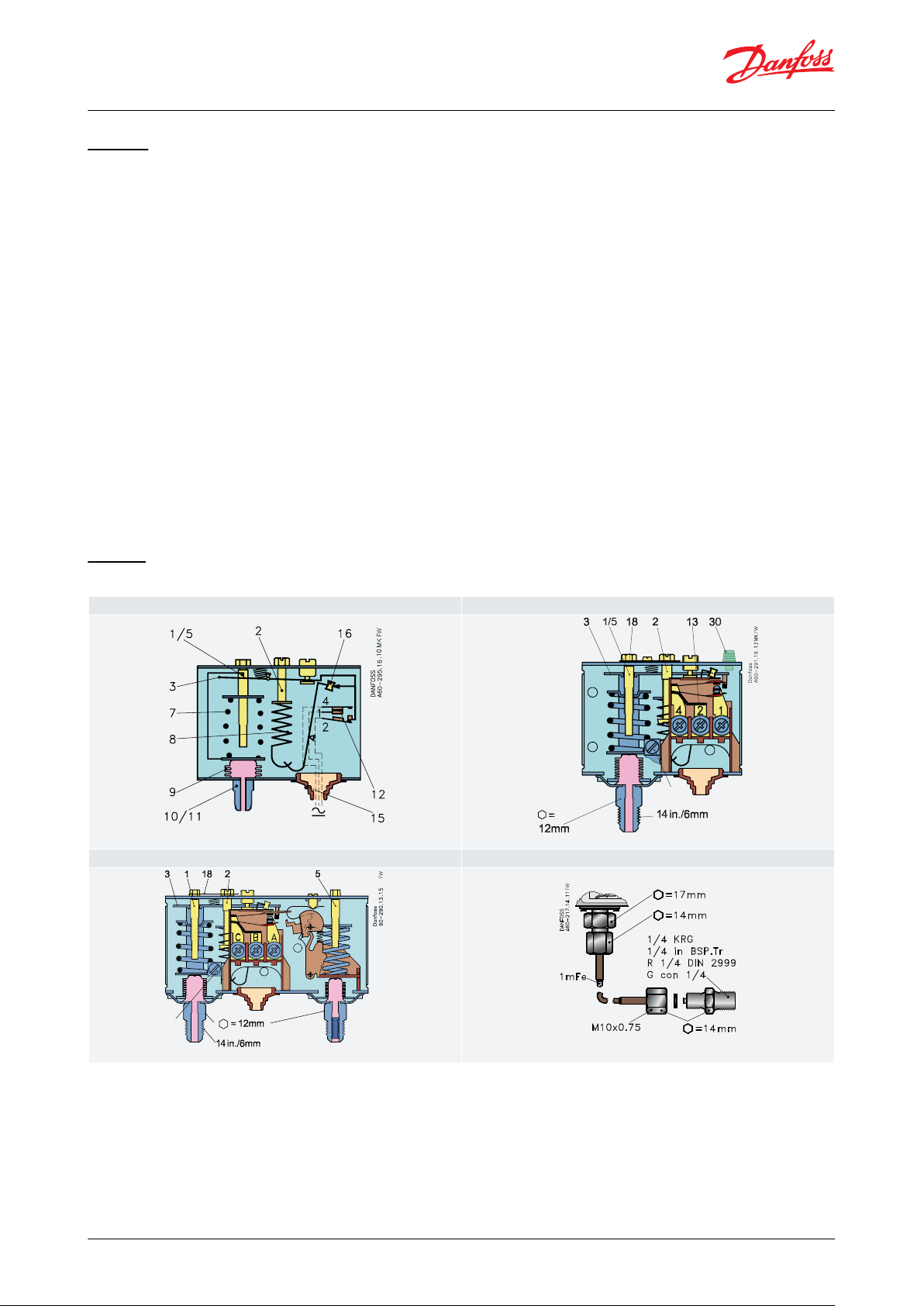
Design
Table 5: Design
© Danfoss | Climate Solutions | 2021.10 AI213186439478en-001201 | 4
Page 5

1.2.3.5.7.8.9.
10.
11.
12.
13.
14.
15.
16.
18.
30.
Low pressure setting spindle, (LP)
Dierential setting spindle
Main arm
High pressure setting spindle, (HP)
Main spring
Dierential spring
Bellows
LP connection
HP connection
Switch
Terminals
Earth terminal
Cable entry
Tumbler
Locking plate
Reset button
KP 7W,
are
KP 7W, solder
MK
1
MK.FW
KP 7BS
MK
25
30
1
Pressure switch, Type KP
The switch in the KP has a snap-action function where the bellows move only when the cut-in or cut-out value is
reached.
The bellows are connected to the low or high pressure side of the system through connection (10) or (11).
The design of the KP gives the following advantages:
• high contact load
• ultra-short bounce time
• high resistance to pulsation
• vibration resistance up to 4 g in the range 0 – 1000 Hz
• long mechanical and electrical life
Table 6: Design
© Danfoss | Climate Solutions | 2021.10 AI213186439478en-001201 | 5
Page 6

12315182530
Pressure setting spindle
Dierential setting spindle
Main arm
Cable entry
Locking plate
Int. reset arm
Ext. reset button
KP 1, KP 2, KP 5, KP 6, KP 7B, KP 7S and KP 7W
KP 15 and KP 17W
=12
84
44
6128 – 30
44
122
61
28 – 32
28 – 30
=12
Danfoss
60-306.16
KP 1A, KP 2A and KP 5A
KP 15A, KP 7AS and KP 7ABS
84
44
6125
=12
Danfoss
60-303.19
=12
122
61
25 – 29
44
Danfoss
60-305.12
Pressure switch, Type KP
Types KP1, KP1A, KP2, KP6, KP6A, KP7 and KP17 units with designation W, B or S have been tested and approved by
TÜV, Rheinland in accordance with EN 12263.
Types KP6, KP6A, KP7 and KP17 have a double bellows: an outer bellows and a regulating bellows. When system
pressure exceeds the set value, the KP will automatically stop the plant. The double bellows system prevents loss of
charge in the event of bellows rupture.
A rupture in the inner bellows will cause the control cut-out pressure to fall about 3 times less the set value, thus the
refrigeration plant compressor will stop.
A rupture in the outer bellows will cause the control cut-out pressure to fall to about 3 bar under the set value, thus
providing a fail-safe function.
Versions with designation W or AW cut in again automatically when the pressure has fallen to the set value minus
the dierential.
Versions with designation B or AB can be cut in manually with the external reset button when the pressure in KP1
has increased 0.7 bar above set value and in KP6 and KP7 has fallen 4 bar under the set value.
Versions with designation S or AS can be cut in manually with the internal reset arm when the pressure has fallen 4
bar under the set value.
All KP pressure switches, including those which are PED-approved, operate independently of changes in the
ambient temperature around the control housing. Therefore the set cut-out pressure and dierential are held
constant provided the permissible ambient temperatures are not exceeded.
Dimensions [in] and weight [lb]
Table 7: Pressure switchess with are connection
Table 8: M10 × 0.75 connection
© Danfoss | Climate Solutions | 2021.10 AI213186439478en-001201 | 6
Page 7

KP 1, KP 2, KP 5, KP 7B, KP 7S and KP 7W
KP 15, 1 KP 7W
44
84
61
112 – 114
122
61
112 – 114
112 – 116
44
=12
122
44
6128 – 30
28 – 32
7
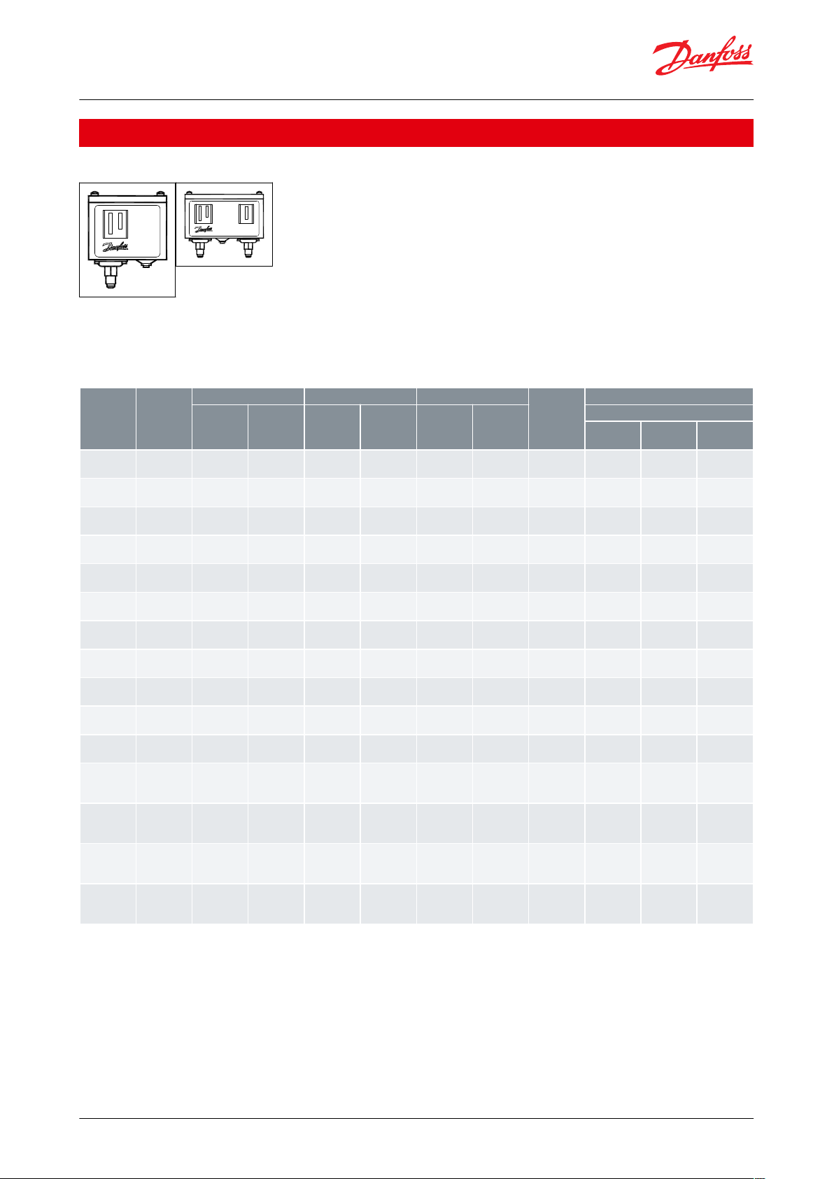
IP55 enclosure
IP55 enclosure for dual types
Pressure switch, Type KP
Table 9: Solder connection
Figure 1: KP with top cover
Net weight:
KP 1, KP 2, KP 5 and KP 7: approx. 0.3 kg
KP 15, KP 17 and KP 7BS: approx. 0.5 kg
KP 1A and KP 5A: approx. 0.3 kg
KP 15A and KP 7ABS: approx. 0.5 kg
Table 10: IP55 enclosure
Figure 2: Weld nipple for KP-A
© Danfoss | Climate Solutions | 2021.10 AI213186439478en-001201 | 7
Page 8
Pressure
Type
Low pressure (LP)
High pressure (HP)
Reset
Contact
system
Code no.
Regulating
range [bar]
Dierential
∆p [bar]
Regulating
range [bar]
Dierential
∆p [bar]
Low
pressure LP
High
pressure
HP
Connection
1/4 in. 6
mm are
1/4 in. ODF
solder
6 mm ODF
solder
Low
KP 1
-0.2 – 7.5
0.7 – 4.0––
Auto–SPDT
060-110166
(1)(4)
060-111266
(4)
060-111066
(4)
Low
KP 1
-0.2 – 7.5
0.7 – 4.0––
Auto–SPDT
060-114166
(2)(4)
––Low
KP 1
-0.9 – 7.0
0.7––
Man. (Min.)
–
SPDT
060-110366
(1)
060-111166
060-110966
Low
KP 2
-0.2 – 5.0
0.5 – 1.5––
Auto–SPDT
060-112066
(1)(4)
–
060-112366
(4)
High
KP 5––
8 – 32
1.8 – 6.0–Auto
SPDT
060-117166
(1)(4)
060-117966
(4)
060-117766
(4)
High
KP 5––
8 – 323–
Man. (Max.)
SPDT
060-117366
(1)
060-118066
–
Dual
KP 15
-0.2 – 7.5
0.7 – 4.0
8 – 324Auto
Auto
SPDT + LP
signal
060-124166
(4)
060-125466
(4)
–
Dual
KP 15
-0.2 – 7.5
0.7 – 4.0
8 – 324Auto
Man. (Max.)
SPDT + LP
signal
060-124366
(1)
––Dual
KP 15
-0.2 – 7.5
0.7 – 4.0
8 – 324Auto
Man. (Max.)
SPDT + LP
signal
060-114866
(2)
––Dual
KP 15
-0.9 – 7.0
0.7
8 – 32
4
Man. (Min.)
Man. (Max.)
SPDT + LP
signal
060-124566
(1)
––Dual
KP 15
-0.9 – 7.0
0.7
8 – 324Conv.
(3)
Conv.
(3)
SPDT + LP
signal
060-126166––
Dual
KP 15
-0.2 – 7.5
0.7 – 4.0
8 – 324Auto
Auto
SPDT + LP
and HP sig-
nal
060-126566
(1)(4)
060-129966
(4)
–
Dual
KP 15
-0.2 – 7.5
0.7 – 4.0
8 – 324Auto
Man. (Max.)
SPDT + LP
and HP sig-
nal
060-126466
(1)
060-128466
(1)
–
Dual
KP 15
-0.2 – 7.5
0.7 – 4.0
8 – 324Conv.
(3)
Conv.
(3)
SPDT + LP
and HP sig-
nal
060-115466
(4)
060-001066
(4)
–
Dual
KP 15
-0.9 – 7.0
0.7
8 – 324Conv.
(3)
Conv.
(3)
SPDT + LP
and HP sig-
nal
060-122066––
Pressure switch, Type KP
Ordering
Figure 3: KP
For complete list of approved refrigerants, visit www.products.danfoss.com and search for individual code numbers,
where refrigerants are listed as part of technical data.
Table 11: For R22, R134a, R404A, R407A, R407C, R407F, R422B, R422D, R448A, R449A, R450A, R452A, R507A, R513A and
selected A2L refrigerants: R455A, R454C, R1234yf, R1234yz, R1234ze
(1)
(1)
Available in Asia market with code 060-xxxx91
Available in Asia market with code 060-xxxx91
(2)
(2)
Pressure switches with gold-plated contacts
Pressure switches with gold-plated contacts
(3)
(3)
Conv.: optional automatic or manual reset
Conv.: optional automatic or manual reset
(4)
(4)
Enclosure IP44
Enclosure IP44
For complete list of approved refrigerants, visit www.products.danfoss.com and search for individual code numbers,
where refrigerants are listed as part of technical data.
© Danfoss | Climate Solutions | 2021.10 AI213186439478en-001201 | 8
Page 9

Pressure
Type
Low pressure (LP)
High pressure (HP)
Reset
Contact
system
Code no.
Regulating
range [bar]
Dierential
∆p [bar]
Regulating
range [bar]
Dierential
∆p [bar]
Low
pressure LP
High
pressure HP
Connection
M10 × 0.75
1 m cap.
tube with
M10 × 0.75
Low
KP 1A
-0.2 – 7.5
0.7 – 4.0––
Auto–SPDT
060-116266
(1)
060-116066
(2)
Low
KP 1A
-0.9 – 7.0
0.7––
Man. (Min.)
–
SPDT
–
060-116166
High
KP 5A––
8 – 32
1.8 – 6.0–Auto
SPDT
–
060-123066
High
KP 5A––
8 – 323–
Man. (Max.)
SPDT
060-115366
(1)
060-123166
Dual
KP 15A
-0.2 – 7.5
0.7 – 4.0
8 – 324Auto
Auto
SPDT + LP
and HP signal
060-129566
060-129366
Dual
KP 15A
-0.2 – 7.5
0.7 – 4.0
8 – 324Auto
Man. (Max.)
SPDT + LP
and HP signal
060-129666
060-129466
Dual
KP 15A
-0.9 – 7.0
0.7
8 – 32
4
Conv.
(3)
Conv.
(3)
SPDT + LP
signal
–
060-128366
Pressure
Type
(1)
Low pressure (LP)
High pressure (HP)
Reset
Contact
system
Code no.
Regulating
range [bar]
Dierential
∆p [bar]
Regulating
range [bar]
Dierential
∆p [bar]
Low
pressure LP
High
pressure HP
Connection
1/4 in. 6 mm
are
6 mm ODF
solder
Low
KP 1
-0.2 – 7.5
0.7 – 4.0––
Auto–SPDT
060-110166
(2)(3)
060-111066
(3)
Low
KP 1
-0.9 – 7
0.7––
Man. (Min.)
–
SPDT
060-110366
(2)
060-110966
Low
KP 2
-0.2 – 5
0.5 – 1.5––
Auto–SPDT
060-112066
(2)(3)
060-112366
(3)
High
KP 6W––
8 – 42
4 – 10–Auto
SPDT
060-519066
(3)
–
High
KP 6B––
8 – 424–
Man. (Max.)
SPDT
060-519166
–
High
KP 7W––
8 – 32
4 – 10–Auto
SPDT
060-119066
(3)
060-120366
(3)
High
KP 7B––
8 – 324–
Man. (Max.)
SPDT
060-119166
–
High
KP 7S––
8 – 324–
Man. (Max.)
SPDT
060-119266
(3)
–
Dual
KP 7BS––
8 – 324–
Man. (Max.)
Man. (Max.)
SPST
060-120066
–
Dual
KP 17W
-0.2 – 7.5
0.7 – 4
8 – 324Auto
Auto
SPDT + LP
and HP signal
060-127566
(3)
060-127666
(3)
Dual
KP 17W
-0.2 – 7.5
0.7 – 4
8 – 324Auto
Auto
SPDT+ LP sig-
nal
060-126766
(3)
–
Dual
KP 17B
-0.2 – 7.5
0.7 – 4
8 – 324Auto
Man. (Max.)
SPDT
060-126866
060-127466
Dual
KP 17WB
-0.2 – 7.5
0.7 – 4
8 – 324Auto
Conv.
(5)
SPDT + LP
and HP signal
060-539766
(3)(4)
–
Pressure switch, Type KP
Table 12: For R717, R22, R134a, R404A, R407A, R407C, R407F, R422B, R422D, R438A, R448A, R449A, R450A, R452A, R507A,
R513A and selected A2L refrigerants : R455A, R454C, R1234yf, R1234yz, R1234ze
(1)
(1)
Available in Asia market with code 060-xxxx91
Available in Asia market with code 060-xxxx91
(2)
(2)
Enclosure IP44
Enclosure IP44
(3)
(3)
Conv.: optional automatic or manual reset
Conv.: optional automatic or manual reset
Pressure switches PED 2014/68/EU approved; EN 12263
For complete list of approved refrigerants, visit www.products.danfoss.com and search for individual code numbers,
where refrigerants are listed as part of technical data.
Table 13: For R22, R134a, R404A, R407A, R407C, R407F, R410A(for KP6W, KP6B), R422B, R422D, R438A, R448A, R449A, R450A,
R452A, R507A, R513A and selected A2L refrigerants: R455A, R454C, R1234yf, R1234yz, R1234ze
(1)
(1)
W = PSH (pressure switch), B = PZH (pressure switch with ext. reset), S = PZHH (pressure switch with int. reset)
W = PSH (pressure switch), B = PZH (pressure switch with ext. reset), S = PZHH (pressure switch with int. reset)
(2)
(2)
Available in Asia market with code 060-xxxx91
Available in Asia market with code 060-xxxx91
(3)
(3)
Enclosure IP44
Enclosure IP44
(4)
(4)
Factory setting: LP side: Range 1 bar Pe,
Factory setting: LP side: Range 1 bar Pe,
(5)
(5)
Conv.: optional automatic or manual reset
Conv.: optional automatic or manual reset
Di. 1 bar; HP side: Range 18 bar Pe, Di. 4 bar xed
Di. 1 bar; HP side: Range 18 bar Pe, Di. 4 bar xed
For complete list of approved refrigerants, visit www.products.danfoss.com and search for individual code numbers,
where refrigerants are listed as part of technical data.
© Danfoss | Climate Solutions | 2021.10 AI213186439478en-001201 | 9
Page 10

Pressure
Type
Low pressure (LP)
High pressure (HP)
Reset
Contact
system
Code no.
Regulating
range [bar]
Dierential
∆p [bar]
Regulating
range [bar]
Dierential
∆p [bar]
Low
pressure LP
High
pressure HP
Connection
M10 × 0.75
1 m cap.
tube with
M10 × 0.75
Low
KP 1A
-0.2 – 7.5
0.7 – 4.0––
Auto–SPDT
060-116266
(1)
060-116066
(2)
Low
KP 1A
0.9 – 7
Fixed 0.7––
Man. (Min.)
–
SPDT
–
060-116166
Dual
KP 7ABS––
8 – 32
Fixed 4
–
Man. (Max.)
Man. (Max.)
SPST
–
060-120566
Voltage
Current range
Power factor (cos phi)
Frequency
250V AC
≤ 4.0 A
PF ≥ 0,400
50Hz/60Hz
250V AC
> 4.0 to 6.0 A
PF ≥ 0,594
50Hz/60Hz
250V AC
> 6.0 to 16,0 A
PF ≥ 0,780
50Hz/60Hz
Pressure switch, Type KP
Table 14: For R717, R22, R134a, R404A, R407A, R407C, R407F, R422B, R422D, R438A, R448A, R449A, R450A, R452A, R507A,
R513A and selected A2L refrigerants: R455A, R454C, R1234yf, R1234yz, R1234ze
(1)
(1)
Available in Asia market with code 060-xxxx91
Available in Asia market with code 060-xxxx91
(2)
(2)
Enclosure IP44
Enclosure IP44
Use with A2L refrigerants (R455A, R454C, R1234yf, R1234yz, R1234ze)
CAUTION:
While using A2L refrigerants the following safety requirements should be followed
Safety requirements
1.
KP pressure switches shall only be employed in the units/systems which comply with the requirements for
charge limits and requirements for avoiding ignition sources of IEC 60335-2-24, IEC 60335-2-40, IEC 60335-2-89,
ISO 5149, EN378-1 or equivalent
2.
Applying the overload on the KPs must be prevented. If by any chance it was damaged, the system / unit shall be
stopped and KP shall be replaced as necessary
3.
Electrostatic discharge protection and Electrical leakage protection shall be surely implemented by grounding or
other measures
4.
Only trained personnel are authorized to handle ammable refrigerants systems and may do the installation,
maintenance and exchange of the switch by using appropriate tools
5.
It is recommended to regularly check the function of KP switch
6.
The KP pressure switches shall be used as built-in devices that cannot be accessible from outside and protected
against mechanical impact
7.
The KPs shall be installed in water free environment. In addition, protection of the KP switches against corrosion
shall be taken into consideration when using them in corrosive environment
8.
Cables shall not be in contact with sharp edges. The cables shall be connected with adequate stress relieve in
order to prevent that pulling forces can be carried thorough the cable to the terminal
9.
In the event of pressure pulsation in the system, where switch is connected, these must be eectively dumped to
prevent failure of the bellows. The cycle frequency of KP switch shall be kept as low as possible
10.
The KP switches shall not be installed in places where high level of vibration is present
Electrical rating for use with A2L refrigerants (R455A, R454C, R1234yf, R1234yz, R1234ze)
AC-3: 16 A / 250 V AC
AC-15: 10 A / 250 V AC
Table 15: Electrical rating
© Danfoss | Climate Solutions | 2021.10 AI213186439478en-001201 | 10
Page 11

Low pressure
Manual reset
(1)
Automatic reset
Automatic reset
Manual reset
High pressure
Manual reset
(1)
Manual reset
Automatic reset
Automatic reset
Pressure switch, Type KP
Pressure switch setting with convertible reset
Table 16: Pressure switch setting with convertible reset
(1)
(1)
Factory setting
Factory setting
© Danfoss | Climate Solutions | 2021.10 AI213186439478en-001201 | 11
Page 12

File name
Document type
Document topic
Approval authority
01 202 PL-Q-11 0004
Quality - Assurance Certicate
PED
TÜV
01 202 641-B-19 0006-02
Pressure - Safety Certicate
PED
TÜV
17.20386.258
Marine - Safety Certicate
Marine approval
RMRS
LR 17-20047(E1)
Marine - Safety Certicate
Marine approval
LR
FZ2015006584
Logo Printing Permission
-
CCC
ELE-086320XG-003
Marine - Safety Certicate
Marine approval
RINA
BV 03650-K0 BV
Marine - Safety Certicate
Marine approval
BV
RU Д-DK.ГА02.В.03367
EAC Declaration
EMC
EAC
DNV GL TAA00001VZ
Marine - Safety Certicate
Marine approval
DNV GL
RU C-DK.БЛ08.В.00063_18
Electrical - Safety Certicate
EMC/LVEc
EAC
UA.1O146.D.00075-19
UA Declaration
EMCD/LVD
LLC CDC EURO TYSK
UL E31024
Electrical - Safety Certicate
-
UL
Pressure switch, Type KP
Certicates, declarations, and approvals
The list contains all certicates, declarations, and approvals for this product type. Individual code number may have
some or all of these approvals, and certain local approvals may not appear on the list.
Some approvals may change over time. You can check the most current status at danfoss.com or contact your local
Danfoss representative if you have any questions.
Table 17: Certicates, declarations, and approvals
CE-marked in accordance with:
• LVD 2014/35/EU (EN 60947-1, EN 60947-4-1, EN 60947-5-1)
• PED 2014/68/EU, category IV (EN 12263): KP 1, KP 2, KP 6, KP 7 and KP 17
• Underwriters Laboratories Inc., UL listed China Compulsory Certicate, CCC
Ship approvals
Det Norske Veritas and Germanischer Lloyd, DNV GL
Registro Italiano Navale, RINA
Bureau Veritas, BV
Lloyd’s Register, LR
Russian Maritime Register of Shipping, RMRS
© Danfoss | Climate Solutions | 2021.10 AI213186439478en-001201 | 12
Page 13

Online support
Danfoss oers a wide range of support along with our products, including digital product information, software,
mobile apps, and expert guidance. See the possibilities below.
The Danfoss Product Store
The Danfoss Product Store is your one-stop shop for everything product related—no matter where
you are in the world or what area of the cooling industry you work in. Get quick access to essential
information like product specs, code numbers, technical documentation, certications, accessories,
and more.
Start browsing at store.danfoss.com.
Find technical documentation
Find the technical documentation you need to get your project up and running. Get direct access to
our ocial collection of data sheets, certicates and declarations, manuals and guides, 3D models
and drawings, case stories, brochures, and much more.
Start searching now at www.danfoss.com/en/service-and-support/documentation.
Danfoss Learning
Danfoss Learning is a free online learning platform. It features courses and materials specically
designed to help engineers, installers, service technicians, and wholesalers better understand the
products, applications, industry topics, and trends that will help you do your job better.
Create your Danfoss Learning account for free at www.danfoss.com/en/service-and-support/learning.
Get local information and support
Local Danfoss websites are the main sources for help and information about our company and
products. Find product availability, get the latest regional news, or connect with a nearby expert—all
in your own language.
Find your local Danfoss website here: www.danfoss.com/en/choose-region.
Any information, including, but not limited to information on selection of product, its application or use, product design, weight, dimensions, capacity or any other
technical data in product manuals, catalogues descriptions, advertisements, etc. and whether made available in writing, orally, electronically, online or via download,
shall be considered informative, and is only binding if and to the extent, explicit reference is made in a quotation or order conrmation. Danfoss cannot accept any
responsibility for possible errors in catalogues, brochures, videos and other material. Danfoss reserves the right to alter its products without notice. This also applies to
products ordered but not delivered provided that such alterations can be made without changes to form, t or function of the product. All trademarks in this material
are property of Danfoss A/S or Danfoss group companies. Danfoss and the Danfoss logo are trademarks of Danfoss A/S. All rights reserved.
© Danfoss | Climate Solutions | 2021.10 AI213186439478en-001201 | 13
 Loading...