

Page 1
User Manual
PLUS+1® GUIDE Software
PLUS+1 Compliant KEP 3-Pt Foot Pedal
Function Block
www.danfoss.com
Page 2

User Manual
PLUS+1 Compliant KEP 3-Pt Foot Pedal Function Block User Manual
Revision history Table of revisions
Date Changed Rev
August 2021 Fixed the version numbers 0202
June 2021 First release of the user manual 0201
2 | © Danfoss | August 2021 AQ152886481726en-0202
Page 3

User Manual
PLUS+1 Compliant KEP 3-Pt Foot Pedal Function Block User Manual
Contents
Introduction
Inputs, Outputs, and Signals
Inputs....................................................................................................................................................................................................5
Outputs................................................................................................................................................................................................ 5
Diagnostics Signals..........................................................................................................................................................................6
Status Outputs...................................................................................................................................................................................6
Fault Outputs..................................................................................................................................................................................... 6
Configuration
Configuration Parameters.............................................................................................................................................................8
Setup Configuration Parameter Inputs............................................................................................................................ 10
NV Page............................................................................................................................................................................................. 11
Configuring Inputs with Legacy MC Controllers................................................................................................................ 11
Configure a Multifunction Input with Legacy Controllers.........................................................................................12
Configure an Analog Input with Legacy Controllers................................................................................................... 12
Configure a Digital/Analog Input for Legacy Controllers.......................................................................................... 13
Configuring Inputs with SC Controllers and Non-Legacy MC Controllers................................................................ 13
Configure a Multifunction Input......................................................................................................................................... 13
Configure a Digital/Analog Input....................................................................................................................................... 14
Using Namespaces........................................................................................................................................................................ 15
Change Namespace Value.....................................................................................................................................................15
Calibration
Calibrate the Foot Pedal..............................................................................................................................................................16
Calibration Windows and Default Calibration Values.......................................................................................................16
Calibration Values and Deadbands......................................................................................................................................... 17
Customizable Service Screens
Add Service Screens to the Service Tool................................................................................................................................19
KEP Foot Pedal Service Screen.................................................................................................................................................. 19
Calibration Service Screen..........................................................................................................................................................21
Pedal Reusable Panel....................................................................................................................................................................22
©
Danfoss | August 2021 AQ152886481726en-0202 | 3
Page 4
User Manual
PLUS+1 Compliant KEP 3-Pt Foot Pedal Function Block User Manual
Introduction
The KEP 3Pt Foot Pedal Function Block provides parameters and logic used to integrate a KEP 3Pt Foot
Pedal into your application.
The SnsrPwr input receives the sensor power voltage applied to the pedal sensor. This voltage
•
remains constant.
The Pedal input receives the voltage output by the pedal sensor. The position of the pedal varies this
•
voltage.
The function block makes ratiometric comparisons of the Pedal and SnsrPwr inputs. This comparison
produces Out values that range from ±10000 (±100.00%).
4 | © Danfoss | August 2021 AQ152886481726en-0202
Page 5
User Manual
PLUS+1 Compliant KEP 3-Pt Foot Pedal Function Block User Manual
Inputs, Outputs, and Signals
This section provides information on the inputs, outputs, diagnostic signals, and fault and status
conditions for the KEP 3Pt Foot Pedal Function Block.
Inputs
The Function Block Inputs table describes the inputs for the KEP 3Pt Foot Pedal Function Block.
Function Block Inputs
Item Type Range Description
Para Bus —— Allows common configuration parameters to be applied to multiple function blocks.
See Setup Configuration Parameter Inputs on page 10 for more information.
SnsrPwr Bus 0–5250 mV Inputs a signal with the sensor power voltage (reference voltage) that the controller applies to the
sensor power pin of the pedal.
Pedal Bus 0–5250 mV Inputs a signal with the voltage output by the pedal sensor. The position of the pedal varies this
voltage.
The function block makes a ratiometric comparison of the Pedal and SnsrPwr inputs to produce Out
values from ±10000 (±100.00%).
Outputs
The Outputs table describes the output signals from the function block.
Outputs
Output Type Range Description [Unit]
Status U16 —— Indicates the calibration and setup status of the function block.
0x0000: Function block is OK
0x8001: Function block is not calibrated
0x8002: Function block is partially calibrated
0x8008: Invalid setup/calibration
This output uses a bitwise-reporting scheme where multiple items can be reported at a time.
Fault U16 —— Indicates the operating condition of the function block.
0x0000: Function block is OK
0x8001: Input value is too low
0x8002: Input value is too high
0x8004: Short circuit
0x8008: Open circuit
This output uses a bitwise-reporting scheme where multiple items can be reported at a time.
Out Outputs a bus that contains the Pedal_Psn signal.
Pedal_Psn U16 0–±10000 Indicates the position of the foot pedal.
Reverse: -10000 (-100.00%)
Neutral: 0 (0%)
Forward: 10000 (100.00%)
[0.01%]
Pedal_Pressed BOOL T/F Indicates whether the pedal is pressed. For more information on the PressedThreshold parameter, see
Configuration Parameters on page 8.
T: Pedal is pressed
F: Pedal is not pressed
©
Danfoss | August 2021 AQ152886481726en-0202 | 5
Page 6
User Manual
PLUS+1 Compliant KEP 3-Pt Foot Pedal Function Block User Manual
Inputs, Outputs, and Signals
Diagnostics Signals
Diagnostic signals provide indicators of failure states and tools for calibrating the failure indicators. Refer
to the following table for more information on diagnostic signals from the KEP 3Pt Foot Pedal Function
Block.
Diagnostic Signals
Signal Type Range Description [Unit]
Enabled BOOL T/F Indicates that the calibration output is enabled or disabled.
T: Nom_Signal sets the Pedal_Psn output.
F: Pedal_Psn output is set to 0.
Pedal_Ratio U16 0-10000 The ratio of Pedal_Signal voltage compared to Sensor_Power voltage.
[0.01%]
CalLow_Temp U16 0-10000 A temporary calibration point stored by the function block. After all points calibrate, the function
block records this value in memory.
[0.01% of Snsr_Pwr]
CalHigh_Temp U16 0-10000 A temporary calibration point stored by the function block. After all points calibrate, the function
block records this value in memory.
[0.01% of Snsr_Pwr]
CalLow_Pt U16 0-10000 Identifies the start of a 20% window to validate the low calibration point.
[0.01% of Snsr_Pwr]
CalHi_Pt U16 0-10000 Identifies the start of a 20% window to validate the high calibration point.
[0.01% of Snsr_Pwr]
Input_TL_Pt U16 0-10000 The minimum allowed ratio of Pedal_Signal to Snsr_Pwr voltage. If the ratio is below this threshold
for more than the value set in FltDetectTm, the Fault signal will declare 0x8001 (Input value is too
low).
[0.01% of Snsr_Pwr]
Input_TH_Pt U16 0-10000 The maximum allowed ratio of Pedal_Signal to Snsr_Pwr voltage. If the ratio is above this threshold
for more than the value set in FltDetectTm, the Fault signal will declare 0x8002 (Input value is too
high).
[0.01% of Snsr_Pwr]
Status Outputs
Status outputs indicate calibration settings and setup status for the KEP 3Pt Foot Pedal Function Block.
During calibration, the Pedal_Psn signal in the Out bus is zero.
The following table lists all the status conditions output by the KEP 3Pt Foot Pedal Function Block.
Status Conditions
Condition Status Pedal_Psn Signal Comment
Block is OK. 0x0000 0–±10000 Normal output of the Pedal_Psn signal.
Block is not calibrated. 0x8001
0 ——Block is partially calibrated. 0x8002
Invalid setup/calibration. 0x8008
Fault Outputs
The Fault outputs indicate the operating condition of the KEP 3Pt Foot Pedal Function Block.
All fault conditions set the Pedal_Psn signal in the Out bus to zero.
The following table lists all the fault conditions output by the KEP 3Pt Foot Pedal Function Block.
6 | © Danfoss | August 2021 AQ152886481726en-0202
Page 7
User Manual
PLUS+1 Compliant KEP 3-Pt Foot Pedal Function Block User Manual
Inputs, Outputs, and Signals
Fault Conditions
Condition Fault Pedal_Psn Signal Comment
Block is OK. 0x0000 0–±10000 Normal output of the Pedal_Psn signal.
Input value is too low. 0x8001
Input value is too high. 0x8002
Short circuit. 0x8004
Open circuit. 0x8008
0 ——
©
Danfoss | August 2021 AQ152886481726en-0202 | 7
Page 8

User Manual
PLUS+1 Compliant KEP 3-Pt Foot Pedal Function Block User Manual
Configuration
This section provides information and instructions on configuring the KEP 3Pt Foot Pedal Function Block
and other supporting pages.
Configuration Parameters
Configuration parameters control the functions of the functional block. Configure these parameters to
customize the function block for your application.
To view the configuration parameters, enter the KEP 3Pt Foot Pedal Function Block.
For more information about the NV page, see NV Page on page 11.
8 | © Danfoss | August 2021 AQ152886481726en-0202
Page 9

User Manual
PLUS+1 Compliant KEP 3-Pt Foot Pedal Function Block User Manual
Configuration
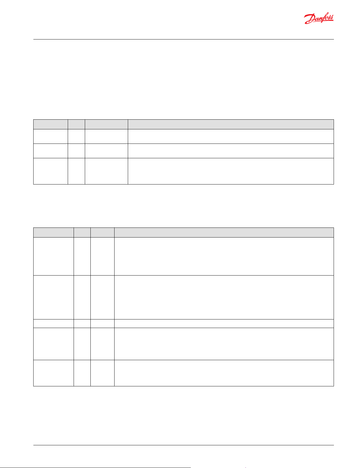
KEP 3Pt Function Block Configuration Parameters
Input Type Range Description [Unit]
CalMode U8 0–3 Selects the calibration mode that determines the Cal_Hi, Cal_Mid, and
Cal_Low calibration values.
0: disables calibration by the function block. The PLUS+1 Service Tool
program must download the calibration values.
1: captures calibration values using calibration or use the PLUS+1 Service
Tool program to directly download calibration values.
During calibration, the function block captures calibration values that fall
within defined windows as you move the pedal through its operating
range and clears all calibration values when you disconnect the pedal
sensor.
2: uses the Default calibration values stored in the NV page.
3: sets all calibration values to zero.
RturnToNeut BOOL T/F Determines when the function block enables its Pedal_Psn signal after a
controller startup, a calibration procedure, or a cleared Fault condition.
(The Pedal_Psn signal is in the Out bus.)
T: the Pedal input voltage must first fall within the Dband_Low (low
deadband) range before the function block enables its Pedal_Psn signal.
F: the function block immediately enables its Pedal_Psn signal. The Pedal
input voltage does not first have to fall within the Dband_Low (low
deadband) range.
LatchPFlt BOOL T/F Determines when the function block can enable the Pedal_Psn signal
after the function block disabled Pedal_Psn due to an invalid parameter.
The Pedal_Psn signal is in the Out bus.
T: the function block can only enable its Pedal_Psn signal after you
repower the controller.
F: the function block can immediately enable its Pedal_Psn signal.
LatchInFlt BOOL T/F Determines when the function block can enable the Pedal_Psn signal
after it was disabled due to an invalid input.
T: the function block can only enable its Pedal_Psn signal after you
repower the controller.
F: the function block can immediately enable its Pedal_Psn signal.
CalWindow U16 0–2000 Sets the width of the calibration windows.
Calibration windows center on the default Cal_Hi , Cal_Mid, and Cal_Low
calibration values. Memory (NV) components in the NV page store these
values.
During a calibration procedure, Input voltages must fall within the
calibration windows to be captured as valid calibration values.
The CalWindow value is a percentage of the SnsrPwr.
You can change the default calibration values by changing the Default
inputs to the NV components in the NV page.
[0.01%]
CalDetectTm U16 0–65535 Determines the time in which Input voltages must remain in calibration
windows to be captured as valid calibration values during calibration.
[ms]
Dband_Hi U16 0–4999 Determines the width of the upper deadband.
An Input voltage that falls within the upper deadband produces a
Pedal_Psn signal of 10000 (100.00%).
The Dband_Hi deadband extends below the Cal_Hi calibration value.
The function block determines the width of this deadband as a percentage
of the difference between the Cal_Hi and Cal_Low values.
[0.01%]
©
Danfoss | August 2021 AQ152886481726en-0202 | 9
Page 10

User Manual
PLUS+1 Compliant KEP 3-Pt Foot Pedal Function Block User Manual
Configuration
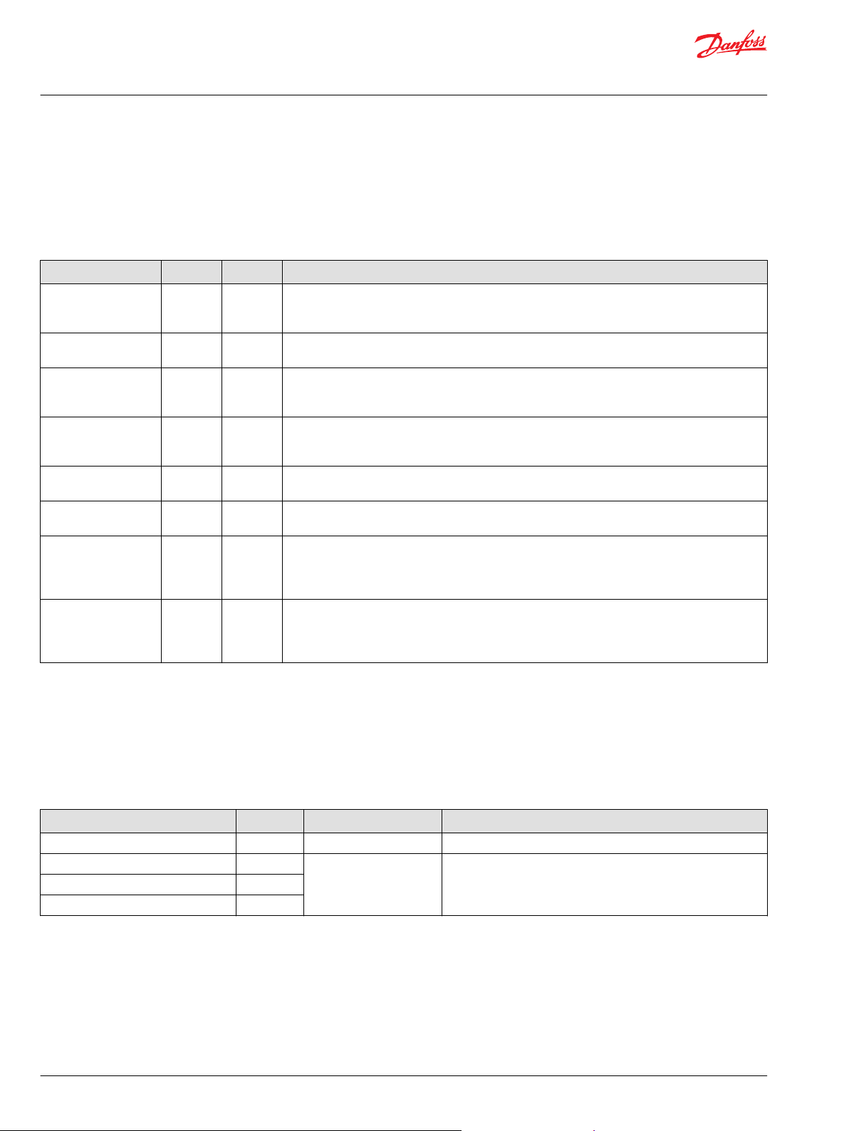
KEP 3Pt Function Block Configuration Parameters (continued)
Input Type Range Description [Unit]
Dband_Mid U16 0–4999 Determines the width of a middle or neutral deadband. An Input voltage
that falls within this deadband produces a Pedal_Psn signal of 0 (0%).
(The Pedal_Psn signal is in the Out bus.)
The Dband_Mid deadband extends above and below the Cal_Mid
calibration value. The function block determines the width of the
deadband that extends:
•
Above the Cal_Mid value as a percentage of the difference between the
Cal_Hi and Cal_Mid values.
•
Below the Cal_Mid value as a percentage of the difference between the
Cal_Mid and Cal_Low values.
[0.01%]
Dband_Low U16 0–4999 Determines the width of the lower deadband.
An Input voltage that falls within this deadband produces a Pedal_Psn
signal of 0 (0%).
The Dband_Low deadband extends above the Cal_Low calibration value.
The function block determines the width of the lower deadband as a
percentage of the difference between the Cal_Hi and Cal_Low values.
[0.01%]
FltDetectTm U16 0–65535 Sets the duration of an abnormal condition after which the function block
triggers a fault or status condition
[ms]
PressedThreshold U16 0-10000 The value of Pedal_Psn signal that triggers the PedalPressed signal. If the
Pedal_Psn signal value exceeds the PressedThreshold value, that
indicates that the user pressed the pedal.
[0.01%]
Setup Configuration Parameter Inputs
Use the parameter (Para) input to apply a common set of configuration parameters to multiple function
blocks. Follow these steps to setup configuration parameter inputs for the application.
1. Create a Parameters page to hold the configuration parameters the function blocks will share.
2. Connect the Parameters page to the Para input of the KEP 3Pt Foot Pedal Function Block.
3. Add the configuration parameters and their values to the Parameters page.
a) Copy the configuration parameters from the function block.
b) Paste the configuration parameters into the Parameters page.
c) Route the parameters to the Para output of the Parameters page.
d) Modify the configuration parameters as needed.
4. In the function block, route each configuration parameter to the Para input bus and connect it to the
corresponding input signal.
To avoid compiler errors, ensure that the Namespace value for each function block is unique.
10 | © Danfoss | August 2021 AQ152886481726en-0202
Page 11

User Manual
PLUS+1 Compliant KEP 3-Pt Foot Pedal Function Block User Manual
Configuration
NV Page
The NV page stores and outputs the calibration values used by the function block.
NV Page
Callout Item Description [Unit]
1 Pedal_CalHi This memory component outputs the Cal_Hi signal used by the function block.
2
3 Pedal_CalLow This memory component outputs the Cal_Low signal used by the function block.
4 DEFAULT A default calibration value.
5 Restore_Default Sets to T (true) when the CalMode signal = 2 (Set Defaults)
6 Cal_Value The Input voltage as a percentage of sensor power.
7 Set_CalHi
8 Write_AllCal Is set to T (true) during calibration after the function completes the capture of all calibration values.
Pedal_CalMid
Set_CalMid
Set_CalLow
This memory component outputs the Cal_Mid signal used by the function block.
When set to T (true), all NV components write their DEFAULT inputs to memory and output these values in
the Cal_Hi, Cal_Mid, and Cal_Low signals.
[0.01%]
Is set to T (true) during calibration when function block detects that the Input voltage signal is within a valid
calibration window.
A true input causes a NV component to hold the Input signal value pending a write to memory.
A T (true) input causes all NV components to write the pending Input signal values to memory and output
these values in the Cal_Hi, Cal_Mid, and Cal_Low signals.
Configuring Inputs with Legacy MC Controllers
Configure the inputs on a legacy MC Controller to customize the controller for your application.
For instructions on configuring an SC Controller, see SC Controller—Input Configuration.
You can route the Pedal input for the function block through:
©
Danfoss | August 2021 AQ152886481726en-0202 | 11
Page 12

User Manual
PLUS+1 Compliant KEP 3-Pt Foot Pedal Function Block User Manual
Configuration
An MFIn (Multifunction Input) on your controller. For instructions, see Configure a Multifunction Input
•
with Legacy Controllers on page 12.
An AnIn (Analog Input) on the controller. For instructions, see Configure an Analog Input with Legacy
•
Controllers on page 12.
A DigAn (Digital/Analog input) on the controller. For instructions, see Configure a Digital/Analog Input
•
for Legacy Controllers on page 13.
You must configure the input that you use to accept a voltage input.
Configure a Multifunction Input with Legacy Controllers Configure the multifunction input (MFIn) to configure the input of a legacy MC controller.
1. In TOP page of the GUIDE template, enter the Inputs page.
2. Enter the MFIn page that routes voltage to the input.
3. Delete the wire to PinConfig0.
Configure an Analog Input with Legacy Controllers Follow these steps to configure an analog input (AnIn) with legacy MC controllers.
1. In the TOP page of the GUIDE template, enter the Inputs page.
2. Enter the AnIn page that routes voltage to the input.
12 | © Danfoss | August 2021 AQ152886481726en-0202
Page 13

User Manual
PLUS+1 Compliant KEP 3-Pt Foot Pedal Function Block User Manual
Configuration
3. Delete the wire as shown in the following figure.
Configure a Digital/Analog Input for Legacy Controllers
Configure a digital/analog input (DigAn) of a legacy MC controller for use with the KEP 3Pt Foot Pedal
Function Block.
1. In the TOP page of the GUIDE template, enter the Inputs page.
2. Enter the DigAn page that receives the input.
3. Delete the wire to PinConfig0.
Configuring Inputs with SC Controllers and Non-Legacy MC Controllers
Configure inputs on an SC controller or a non-legacy MC controller to customize the controller to your
application.
For instructions on configuring inputs with a legacy MC controller, see MC Controller—Input
Configuration .
You can route the Pedal input for the function block through:
An MFIn (Multifunction Input) on your controller. For instructions, see Configure a Multifunction Input
•
on page 13.
A DigAn (Digital/Analog) input on your controller. For instructions, see Configure a Digital/Analog
•
Input on page 14.
You must configure the input that you use to accept a voltage input.
Configure a Multifunction Input
Follow these steps to configure a multifunction input (MFIn) with an SC controller or non-legacy MC
controller.
1. In the TOP page in the GUIDE template, enter the Inputs page.
©
Danfoss | August 2021 AQ152886481726en-0202 | 13
Page 14

User Manual
PLUS+1 Compliant KEP 3-Pt Foot Pedal Function Block User Manual
Configuration
2. Enter the MFIn page that routes voltage to the input of the function block.
3. Delete the wires for Bias, Range, and InputMode as shown in the following figure.
Configure a Digital/Analog Input
Follow these steps to configure a Digital/Analog input (DigAn) with an SC controller or a non-legacy MC
controller.
1. In the TOP page in the GUIDE template, enter the Inputs page.
2. Enter the DigAn page that routes voltage to the input of the function block.
3. Delete the wires for Bias and Range as shown in the following figure.
14 | © Danfoss | August 2021 AQ152886481726en-0202
Page 15

User Manual
PLUS+1 Compliant KEP 3-Pt Foot Pedal Function Block User Manual
Configuration
Using Namespaces
Namespaces can help you successfully compile an application that uses the same function block more
than once.
Change each function block's namespace by setting its Namespace value to something unique. If you do
not change the Namespace value, you cannot compile the application.
The Namespace value adds a unique prefix to each component name.
Also, if you want to use these function blocks' companion Service Tool screens, you must include the
function block's advanced checkpoint with namespace in the application's compiled .lhx file. Use the
function block's Checkpoints page to include the checkpoint.
Change Namespace Value
To successfully compile your application, change the namespace value for function blocks that are used
more than once in an application.
1. In the PLUS+1® GUIDE menu bar, click the Query/Change button.
2. Click on the function block whose namespace you want to set to a unique value.
The Edit Page window opens.
3. In the Edit Page window, enter a meaningful Namespace value.
Namespace values are case-sensitive.
•
To save controller memory, use a short namespace value.
•
4. Press Enter.
5. Repeat these steps to enter unique namespace values for other identical function blocks.
©
Danfoss | August 2021 AQ152886481726en-0202 | 15
Page 16

User Manual
PLUS+1 Compliant KEP 3-Pt Foot Pedal Function Block User Manual
Calibration
This section provides information on calibrating the KEP 3Pt Foot Pedal using the KEP 3Pt Foot Pedal
Function Block.
Calibrate the Foot Pedal
Follow these steps to calibrate the foot pedal.
1. Connect the function block configuration parameters to external signals. For more instructions, see
Setup Configuration Parameter Inputs on page 10.
2. Set the CalMode configuration parameter to 3 to reset the calibration points.
The function block returns 0x8001 (the block is not calibrated).
3. Set CalMode to 1 to enable calibration mode.
The function block calibrates the neutral position of the pedal.
4. Press the pedal forward until the position is within the high calibration window. Hold it in that
position for the time specified by CalDetectTime.
The function block calibrates the point within that calibration window. The calibration is complete
when the function block returns 0x0000 (OK).
5. For 3-point foot pedals, press the pedal back until the position is within the low calibration point.
Hold it in that position for the time specified by CalDetectTime.
The function block calibrates the point within that calibration window. The calibration is complete
when the function block returns 0x0000 (OK).
6. If the function block sets RturnToNeut to T (True), release your foot from the pedal.
7. Set CalMode to 0.
Calibration Windows and Default Calibration Values
The following graph shows the relationship between the default calibration values and the windows in
which the function block captures calibration values during calibration.
16 | © Danfoss | August 2021 AQ152886481726en-0202
Page 17

User Manual
PLUS+1 Compliant KEP 3-Pt Foot Pedal Function Block User Manual
Calibration
Sensor power applied to the foot pedal is 5000 mV.
•
Default Cal_Low value is 1000 (10.00% of sensor power), which puts the default low calibration value
•
at 500 mV. For example: 10.00% of 5000 mV sensor power = 500 mV
Default Cal_Mid value is 5000 (50.00%), which puts the default middle calibration value at 2500 mV.
•
For example: 50.00% of 5000 mV sensor power = 2500 mV
Default Cal_Hi value is 9000 (90.00%), which puts the default high calibration value at 4500 mV. For
•
example: 90.00% of 5000 mV sensor power = 4500 mV
CalWindow value is 1000 (10.00%), which creates calibration windows that are 500 mV wide. For
•
example: 10.00% of 5000 mV sensor power = 500 mV
500 mV wide calibration windows center on the default calibration values.
•
During a calibration procedure, the input voltage must fall between:
•
250–750 mV to be captured as a valid Cal_Low calibration value.
‒
2250—2750 mV to be captured as a valid Cal_Mid calibration value.
‒
4250–4750 mV to be captured as a valid Cal_Hi calibration value.
‒
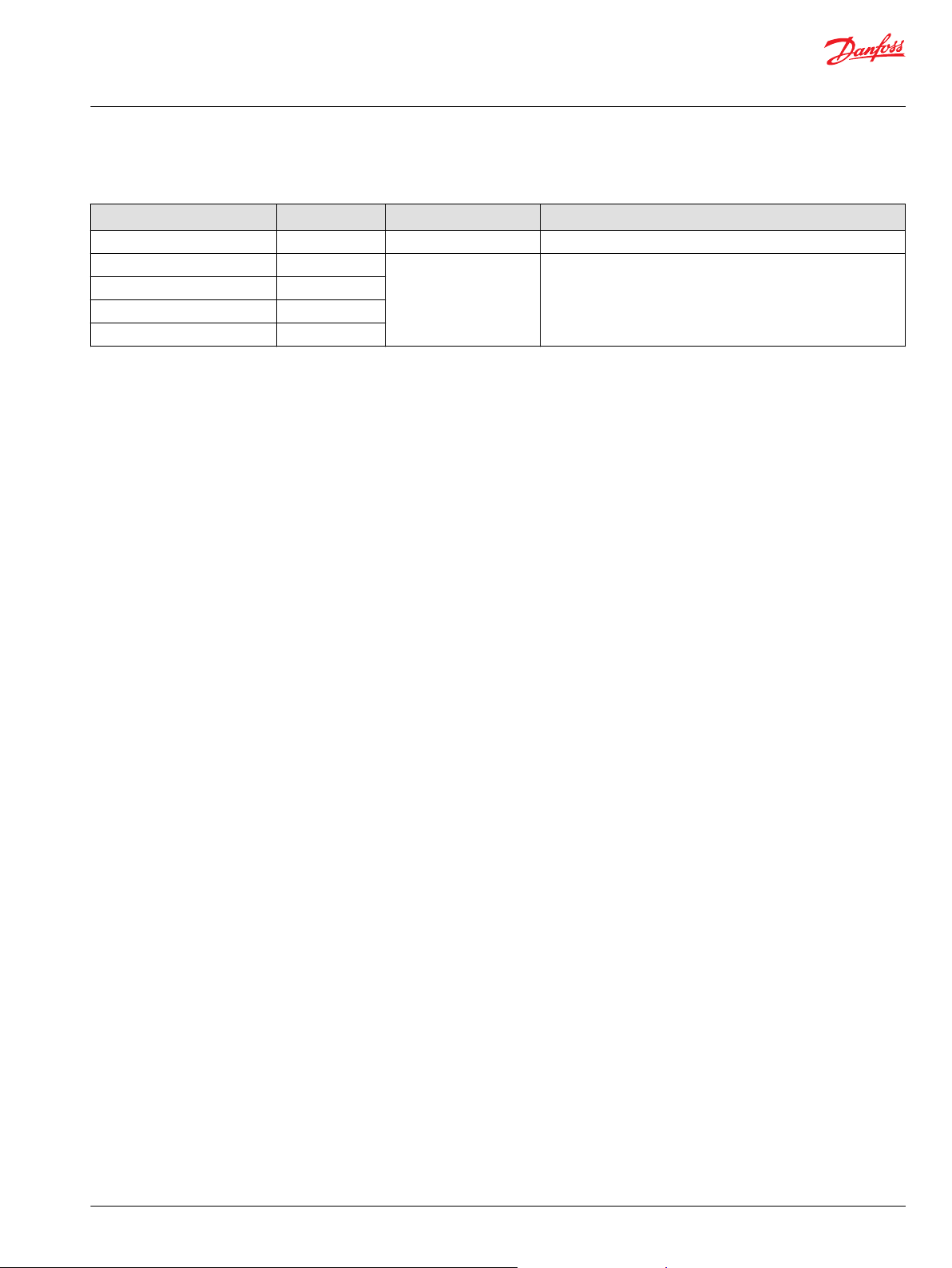
Default Calibration Values
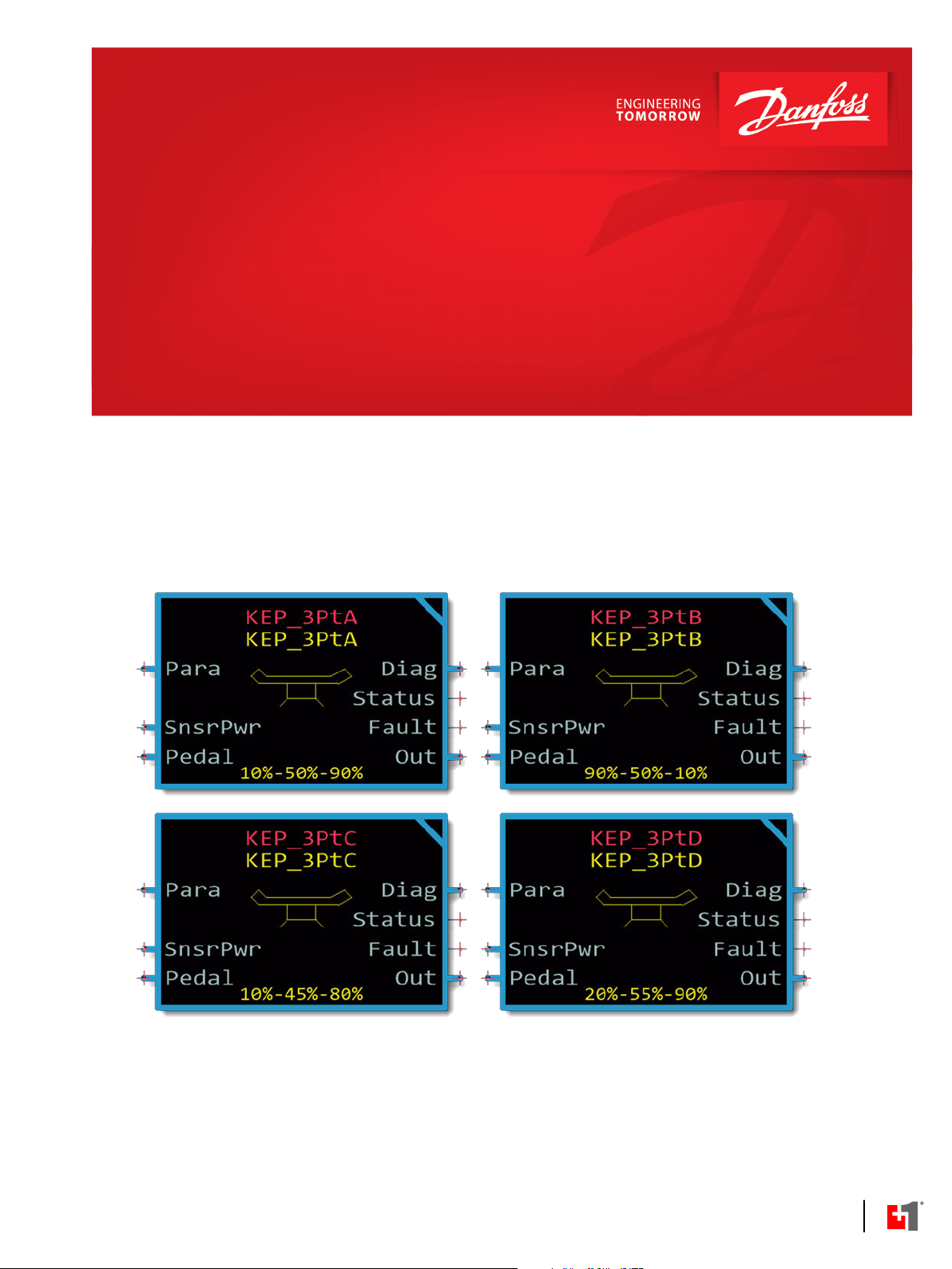
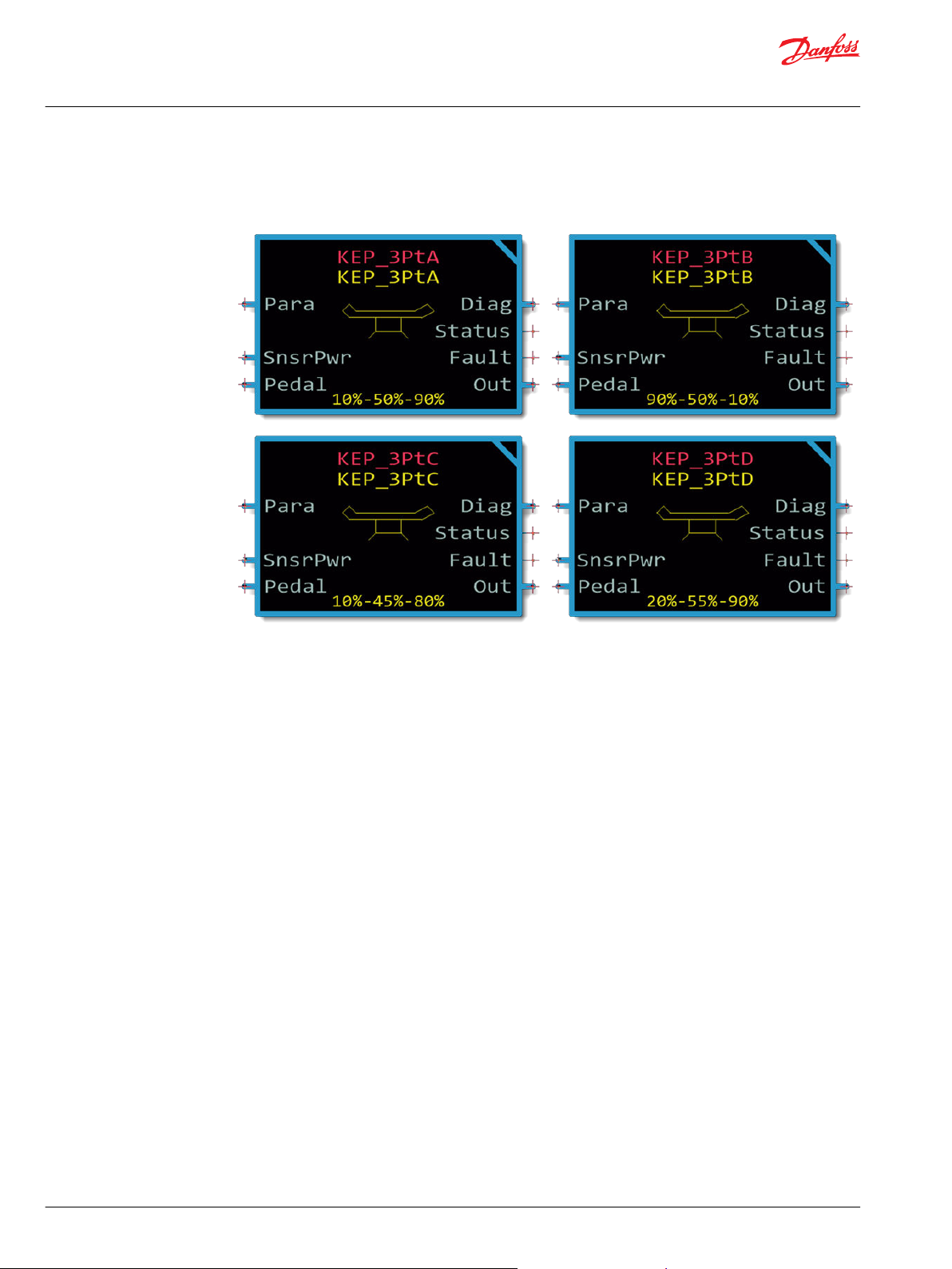
There are four versions of the KEP 3Pt Foot Pedal Function Block: the KEP_3PtA, KEP_3PtB, KEP_3PtC, and
KEP_3PtD function blocks. The function blocks are identical except for their default calibration values.
KEP 3PtFunction Block Default Calibration Values
Function Block Low Calibration Value Middle Calibration Value High Calibration Value
KEP_3PtA
KEP_3PtB
KEP_3PtC
KEP_3PtD
Calibration Values and Deadbands
The following graph shows the:
1000 (10.00%) 5000 (50.00%) 9000 (90.00%)
9000 (90.00%) 5000 (50.00%) 1000 (10.00%)
1000 (10.00%) 4500 (45.00%) 8000 (80.00%)
2000 (20.00%) 5500 (55.00%) 9000 (90.00%)
©
Danfoss | August 2021 AQ152886481726en-0202 | 17
Page 18

User Manual
PLUS+1 Compliant KEP 3-Pt Foot Pedal Function Block User Manual
Calibration
Formulas used by the function block to calculate low and high deadband width.
•
Relationship between the calibration values captured during calibration and the placement of the
•
deadbands.
Deadband Callout Equation
Dband_Hi = 1000 (10%)
Dband_Mid = 500 (5%)
Dband_Low = 1000 (10%)
The graph above shows:
During calibration, the function block captured the:
•
Cal_Hi value at 4700 mV.
‒
Cal_Mid value at 2300 mV
‒
Cal_Low value at 700 mV.
‒
The upper deadband extends below the Cal_Hi value.
•
The upper half of the middle deadband extends above Cal_Mid value.
•
The lower half of the middle deadband extends below the Cal_Mid value.
•
The lower deadband extends above the Cal_Low value.
•
An input voltage that falls within the:
•
High deadband produces a +10000 (+100.00%) output from the function block.
‒
Middle deadband produces a 0 (0%) output from the function block.
‒
Low deadband produces a –10000 (–100.00%) output from the function block.
‒
A
B
C
D
(CalHi - Cal_Mid) x Dband_Hi
For example: 240 mV = (4700 - 2300) x 10%
(Cal_Hi - Cal_Mid) x Dband_Low
For example: 120 mV = (470 - 2300) x 5%
(Cal_Mid - Cal_Low) x Dband_Low
For example: 80 mV = (2300 - 700) x 5%
(Cal_Mid - Cal_Low) x Dband_Low
For example: 160 mV = (2300 - 700) x 10%
18 | © Danfoss | August 2021 AQ152886481726en-0202
Page 19

User Manual
PLUS+1 Compliant KEP 3-Pt Foot Pedal Function Block User Manual
Customizable Service Screens
The function blocks in this library come with pre-made service screens that you can customize when
building your Service Tool application.
The pre-made screens simplify the task of creating Service Tool applications. You can use the screens as
is. Or, you can choose screen components to place in your application.
Refer to the PLUS+1® GUIDE Service Tool Design Manual (Danfoss document number L1320837) for more
information on how to create Service Tool screens.
Add Service Screens to the Service Tool
Follow these steps to add service screens to the PLUS+1® Service Tool.
1. In PLUS+1® GUIDE, locate the service screen file in the Function or Hardware tabs.
2. Right-click on the service screen file then select Copy to Clipboard.
3. Open the PLUS+1® Service Tool.
4. Right-click on Parameter Pages then select Import from Clipboard.
PLUS+1® Service Tool loads the service screen.
KEP Foot Pedal Service Screen
The KEP Foot Pedal service screen displays functional and diagnostic data from the KEP 3Pt Foot Pedal.
KEP 3Pt Foot Pedal Service Screen Fields
Item Description
Inputs ——
Pedal Signal The voltage input from the pedal. The position of the pedal varies the signal.
Sensor Supply The power input in volts to the pedal.
Calibration ——
©
Danfoss | August 2021 AQ152886481726en-0202 | 19
Page 20

User Manual
PLUS+1 Compliant KEP 3-Pt Foot Pedal Function Block User Manual
Customizable Service Screens
KEP 3Pt Foot Pedal Service Screen Fields (continued)
Item Description
Mode The calibration mode that sets the high and low calibration values.
Cal Window The width of calibration windows that center on the calibration points.
Detect Time The time in which Input voltages must remain in calibration windows to be captured as
valid calibration values.
Low Cal Point The start of a 20% window to validate the low calibration point.
High Cal Point The start of a 20% window to validate the high calibration point.
Configuration ——
Return to Neutral The time after a controller startup, a calibration procedure, or a cleared Fault condition
when the function block enables its Pedal_Psn signal.
Latch Parameter Faults Determines when the function block can enable the Pedal_Psn signal after it was
disabled due to an invalid parameter.
Latch Input Faults Determines when the function block can enable the Pedal_Psn signal after it was
disabled due to an invalid input.
Deadband High Determines the width of the upper deadband. Input voltage that falls within the upper
deadband produces a Pedal_Psn signal of 10000 (100.00%).
Deadband Mid
Deadband Low Determines the width of the lower deadband. Input voltage that falls within the lower
Fault Detect Time Sets the time after an abnormal condition when the function block sets a fault or status
Pedal Pressed Threshold The value of Pedal_Psn signal that triggers the PedalPressed signal. If the Pedal_Psn
Outputs ——
Pedal Command Indicates the position of the foot pedal. Up (Released): 0 (0%) Down (fully depressed):
Pedal Pressed Indicates if the pedal is pressed.
Diagnostic ——
Enabled Indicates that the calibration output is enabled or disabled.
Pedal Ratio The ratio of Pedal_Signal voltage compared to Sensor_Power voltage.
Determines the width of a middle or neutral deadband. An Input voltage that falls
within this deadband produces a Pedal_Psn signal of 0 (0%).
deadband produces a Pedal_Psn signal of 0 (0%).
condition.
signal value exceeds the PressedThreshold value, that indicates that the user pressed
the pedal.
10000 (100.00%).
Status Indicates the calibration and setup status of the function block.
Fault Indicates the operating condition of the function block.
20 | © Danfoss | August 2021 AQ152886481726en-0202
Page 21

User Manual
PLUS+1 Compliant KEP 3-Pt Foot Pedal Function Block User Manual
Customizable Service Screens
Calibration Service Screen
The Calibration service screen displays information used to calibrate the KEP 3Pt Foot Pedal.
KEP 3Pt Foot Pedal Calibration Service Screen Fields
Item Description
Input Min The minimum allowed ratio of Pedal_Signal to Snsr_Pwr voltage. If the ratio is below
this threshold for more than the value set in FltDetectTm, the Fault signal will declare
0x8001.
Low Db Determines the width of the lower deadband. Input voltage that falls within the lower
deadband produces a Pedal_Psn signal of 0 (0%).
Mid Db Determines the width of a middle or neutral deadband. An Input voltage that falls
within this deadband produces a Pedal_Psn signal of 0 (0%).
High Db Determines the width of the upper deadband. Input voltage that falls within the upper
deadband produces a Pedal_Psn signal of 10000 (100.00%).
Input Max The maximum allowed ratio of Pedal_Signal to Snsr_Pwr voltage. If the ratio is above
this threshold for more than the value set in FltDetectTm, the Fault signal will declare
0x8002.
Pedal Cmd Indicates the position of the foot pedal. Up (Released): 0 (0%) Down (fully depressed):
10000 (100.00%).
Calibration Window The width of calibration windows that center on the calibration points.
Cal High The start of a 20% window to validate the high calibration point.
Cal Mid The start of a 20% window to validate the middle calibration point.
Cal Low The start of a 20% window to validate the low calibration point.
Pedal Ratio The ratio of Pedal_Signal voltage compared to Sensor_Power voltage.
Status Indicates the calibration and setup status of the function block.
©
Danfoss | August 2021 AQ152886481726en-0202 | 21
Page 22

User Manual
PLUS+1 Compliant KEP 3-Pt Foot Pedal Function Block User Manual
Customizable Service Screens
KEP 3Pt Foot Pedal Calibration Service Screen Fields (continued)
Item Description
Fault Indicates the operating condition of the function block.
Low Calibration Point The start of a 20% window to validate the low calibration point.
Mid Calibration Point The start of a 20% window to validate the middle calibration point.
High Calibration Point The start of a 20% window to validate the high calibration point.
Pedal Reusable Panel
The Reusable Panel provides high-level information for quick access to information from the KEP 3Pt Foot
Pedal.
KEP 3Pt Foot Pedal Reusable Panel Fields
Item Description
Input Command The ratio of Pedal_Signal voltage compared to Sensor_Power voltage.
Position Indicates the position of the foot pedal. Up (Released): 0 (0%) Down (fully depressed):
10000 (100.00%).
Pressed Indicates if the pedal is pressed.
Status Indicates the calibration and setup status of the function block.
Fault Indicates the operating condition of the function block.
Cal High The start of a 20% window to validate the high calibration point.
Cal Mid The start of a 20% window to validate the middle calibration point.
Cal Low The start of a 20% window to validate the low calibration point.
22 | © Danfoss | August 2021 AQ152886481726en-0202
Page 23

Danfoss
Power Solutions GmbH & Co. OHG
Krokamp 35
D-24539 Neumünster, Germany
Phone: +49 4321 871 0
Danfoss
Power Solutions ApS
Nordborgvej 81
DK-6430 Nordborg, Denmark
Phone: +45 7488 2222
Danfoss
Power Solutions (US) Company
2800 East 13th Street
Ames, IA 50010, USA
Phone: +1 515 239 6000
Danfoss
Power Solutions Trading
(Shanghai) Co., Ltd.
Building #22, No. 1000 Jin Hai Rd
Jin Qiao, Pudong New District
Shanghai, China 201206
Phone: +86 21 2080 6201
Products we offer:
Hydro-Gear
www.hydro-gear.com
Daikin-Sauer-Danfoss
www.daikin-sauer-danfoss.com
Cartridge valves
•
DCV directional control
•
valves
Electric converters
•
Electric machines
•
Electric motors
•
Gear motors
•
Gear pumps
•
Hydraulic integrated
•
circuits (HICs)
Hydrostatic motors
•
Hydrostatic pumps
•
Orbital motors
•
PLUS+1® controllers
•
PLUS+1® displays
•
PLUS+1® joysticks and
•
pedals
PLUS+1® operator
•
interfaces
PLUS+1® sensors
•
PLUS+1® software
•
PLUS+1® software services,
•
support and training
Position controls and
•
sensors
PVG proportional valves
•
Steering components and
•
systems
Telematics
•
Danfoss Power Solutions is a global manufacturer and supplier of high-quality hydraulic and
electric components. We specialize in providing state-of-the-art technology and solutions
that excel in the harsh operating conditions of the mobile off-highway market as well as the
marine sector. Building on our extensive applications expertise, we work closely with you to
ensure exceptional performance for a broad range of applications. We help you and other
customers around the world speed up system development, reduce costs and bring vehicles
and vessels to market faster.
Danfoss Power Solutions – your strongest partner in mobile hydraulics and mobile
electrification.
Go to www.danfoss.com for further product information.
We offer you expert worldwide support for ensuring the best possible solutions for
outstanding performance. And with an extensive network of Global Service Partners, we also
provide you with comprehensive global service for all of our components.
Local address:
Danfoss can accept no responsibility for possible errors in catalogues, brochures and other printed material. Danfoss reserves the right to alter its products without notice. This also applies to products
already on order provided that such alterations can be made without subsequent changes being necessary in specifications already agreed.
All trademarks in this material are property of the respective companies. Danfoss and the Danfoss logotype are trademarks of Danfoss A/S. All rights reserved.
©
Danfoss | August 2021 AQ152886481726en-0202
 Loading...