

Page 1
Installation Guide
Multifunctional compressor valve
KDC 65 - 200 (2½ - 8 in.)
148R9532
1 2
148R9532
15
3 4
32
31
30
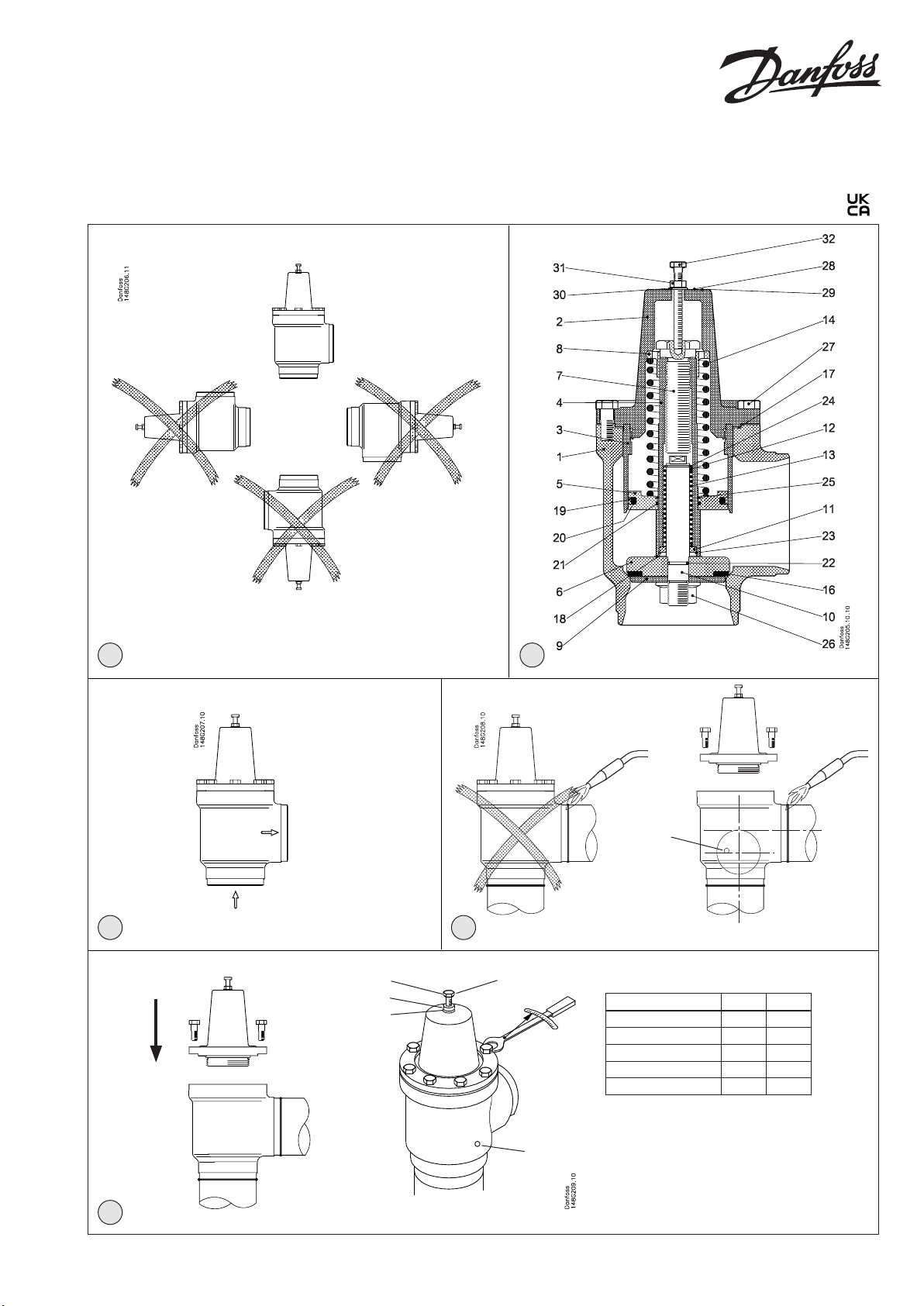
M8
Nm LB-feet
DN 65 75 53
DN 80 44 32
DN 100 75 53
DN 125-150 183 135
DN 200 370 272
15
5
© Danfoss A/S (AC-MCI/MWA), 2021-01 AN105686415739en-000401 | 1
Info for UK customers only:Danfoss Ltd. Oxford Road, UB9 4LH Denham, UK
Page 2
ENGLISH
Installation
Refrigerants
Applicable to HCFC, HFC, R717 (Ammonia)
and R744 (CO2).
Flammable hydrocarbons are not
recommended. The valve is only
recommended for use in closed circuits.
For further information please contact
Danfoss.
Temperature range
KDC: –50/+150°C (–58/+302°F).
Pressure range
The valves are designed for a max. working
pressure of 40 bar g (580 psi g).
Installation (Fig. 1)
The valve must be installed with the
spindle vertically upwards (g. 1).
The valve is designed to withstand a high
internal pressure. However, the piping
system should be designed to avoid liquid
traps and reduce the risk of hydraulic
pressure caused by thermal expansion. It
must be ensured that the valve is protected
from pressure transients like “liquid
hammer” in the system.
Flow direction (Fig. 3)
Important: The ow direction must be from
the cone side towards the branch.
Welding (Fig. 4)
Remove the actuator before welding to
prevent damage to the gasket between
the valve body and bonnet, as well
as the teon gasket in the valve seat.
Only materials and welding methods,
compatible with the valve housing
material, must be welded to the valve
housing. The valve should be cleaned
internally to remove welding debris on
completion of welding and before the
valve is reassembled.
Avoid welding debris and dirt in the
threads of the housing and the bonnet.
Assembly (Fig. 5)
Remove welding debris and any dirt from
pipes and valve body before assembly.
Mount the hexagon screw (pos. 32), the
hexagon ange nut (pos. 31) and the
nylon ring (pos. 30) as shown on g. 5,
and tighten the nut (pos. 31) a few rounds
in order to redraw the valve cone from
the seat. Remove disassembly bolt after
mounting the bonnet and the bonnet
bolts have been tightened. The purpose of
the bolt is to secure insert from falling out
during disassembly and avoid damage of
the Teon seat when bonnet is mounted.
Note! Always pull the valve seat back in
open position before assembling the valve.
Use DN10 steel pipe for a pilot line. It could
be either connected directly to the valve
using NPT ¼” thread or using adapter for
cutting ring.
Tightening (Fig. 5)
Tighten the bonnet with a torque wrench,
to the values indicated in the table (g. 5).
Colours and identication
The KDC valves are painted with a red
oxide primer in the factory. Precise
identication of the valve is made via the
ID ring at the top of the bonnet, as well
as by the stamping on the valve body.
The external surface of the valve housing
must be prevented against corrosion
with a suitable protective coating after
installation and assembly. Protection of
the ID ring when repainting the valve is
recommended.
Maintenance
Dismantling the valve (Fig. 4 and g. 5)
Do not remove the bonnet while the valve
is still under pressure.
Evacuate the pipe system in which the
valve is installed. Remember to evacuate
refrigerant from both sides of the valve
(inlet and outlet). Use service port (pos. 15)
on the valve to evacuate refrigerant from
above the cone.
Assembly (Fig. 5)
Remove welding debris and any dirt from
pipes and valve body before assembly.
Mount the hexagon screw (pos. 32), the
hexagon ange nut (pos. 31) and the
nylon ring (pos. 30) as shown on g. 5,
and tighten the nut (pos. 31) a few rounds
in order to redraw the valve cone from
the seat. Remove disassembly bolt after
mounting the bonnet and the bonnet
bolts have been tightened. The purpose of
the bolt is to secure insert from falling out
during disassembly and avoid damage of
the Teon seat when bonnet is mounted.
Note! Always pull the valve seat back in
open position before assembling the valve.
The valve housing must be free from
stresses (external loads) after installation.
KDC valves must not be mounted in
systems where the outlet side of the valve
is open to atmosphere. The outlet side of
the valve must always be connected to the
system or properly capped o, for example
with a welded-on end plate.
2 | AN105686415739en-000401 © Danfoss A/S (AC-MCI/MWA), 2021-01
Mount the dismantling bolt (pos. 32),
the hexagon ange nut (pos. 31) and the
nylon ring (pos. 30) as shown on g. 5, and
tighten the nut (pos. 31) a few rounds in
order to redraw the valve cone from the
seat. Remove the bolts. Remove the valve
top (actuator).
- Check that the O-ring has not been
damaged.
- Check that the Teon seat is free of
scratches and impact marks.
 Loading...