

Page 1
PLUS+1™ GUIDE
Software
PLUS+1 Compliant JS6000 YP3-Axis Joystick Function Block User Manual
142.0 mm
[5.59]
97.0 mm
[3.82]
144.5 mm
5.69
158.2 mm
6.23
PIN #1
INDICATED
2x 25.2 mm
[1.0]
2x ∅7.0
[.28]
MOUNTING
DIRECTION
#2
LED INDICATO R
LIGHTS
TM
COMPLIANT
CONNECTOR MATES
WITH DEUTCH
CONNECTOR #D TM-06-125A
51.6 mm
47.1 mm
[1.85]
[2.03]
1
12
6
7
1
6
12
7
CONNECTOR MATES
WITH DEUTCH
CONNECTOR #DTM-06-125A
Page 2

PLUS+1 Compliant JS6000 YP3-Axis Joystick Function Block
T
User Manual
About this Manual
Organization
and Headings
o help you quickly find information in this manual, the material is divided into sections,
topics, subtopics, and details, with descriptive headings set in red type. Section titles
appear at the top of every page in large red type.
In the PDF version of this document, clicking an item underlined in blue italic type
you to the referenced page in the document.
Special Text Formatting Controls and indicators are set in bold black type.
Table of Contents
A Table of Contents (TOC) appears on the next page. In the PDF version of this document,
the TOC entries are hyperlinked.
Revision History
Revision Date Comment
Rev BA September 2011
jumps
©2011 Sauer-Danfoss. All rights reserved.
Sauer-Danfoss accepts no responsibility for possible errors in catalogs, brochures and other printed material.
Sauer-Danfoss reserves the right to alter its products without prior notice. This also applies to products already
ordered provided that such alterations can be made without affecting agreed specifications.
All trademarks in this material are properties of their respective owners.
PLUS+1, GUIDE, and Sauer-Danfoss are trademarks of the Sauer-Danfoss Group. The PLUS+1 GUIDE, PLUS+1
2
Compliant, and Sauer-Danfoss logotypes are trademarks of the Sauer-Danfoss Group.
11015589 · Rev BA · September 2011
Page 3

PLUS+1 Compliant JS6000 YP3-Axis Joystick Function Block
User Manual
Contents
JS6000_YP3 Function Block ......................................................................................................................... 4
Overview..................................................................................................................................................... 4
Inputs ........................................................................................................................................................... 4
Outputs ....................................................................................................................................................... 6
Connections and Signals Overview ................................................................................................... 6
Status and Fault Logic ............................................................................................................................ 7
Configuration Settings .......................................................................................................................... 8
About Calibration Windows and Default Calibration Values .................................................. 11
About Calibration Values and Deadbands .................................................................................... 13
MC Controller—Input Configuration .............................................................................................. 15
MC Controller—How to Configure a MFIn............................................................................ 15
MC Controller—How to Configure an AnIn ......................................................................... 16
MC Controller—How to Configure a DigAn ......................................................................... 17
SC Controller—Input Configuration ............................................................................................... 18
SC Controller—How to Configure a MFIn ............................................................................. 18
SC Controller—How to Configure a DigAn .......................................................................... 19
About Pushbutton Wiring .................................................................................................................. 20
MC Controller—Pushbutton Input Configuration ..................................................................... 21
MC Controller—How to Configure a DigIn for a +5 VDC Activated Pushbutton
Input ................................................................................................................................................... 21
MC Controller—How to Configure a DigIn for a Ground-Activated Pushbutton
Input ................................................................................................................................................... 22
MC Controller—How to Configure a DigAn for a +5 VDC Activated Pushbutton
Input ................................................................................................................................................... 23
MC Controller—How to Configure a DigAn for a Ground-Activated Pushbutton
Input ................................................................................................................................................... 24
MC Controller—How to Configure a MFIn for a +5 VDC Activated Pushbutton
Input ................................................................................................................................................... 25
MC Controller—How to Configure a MFIn for a Ground-Activated Pushbutton
Input ................................................................................................................................................... 26
SC Controller—Pushbutton Input Configuration ....................................................................... 27
SC Controller—How to Configure a DigAn for a +5 VDC Activated Pushbutton
Input ................................................................................................................................................... 27
SC Controller—How to Configure a DigAn for a Ground-Activated Pushbutton
Input ................................................................................................................................................... 28
SC Controller—How to Configure a MFIn for a +5 VDC Activated Pushbutton Input
............................................................................................................................................................. 29
SC Controller—How to Configure a MFIn for a Ground-Activated Pushbutton Input
............................................................................................................................................................. 30
About the Para Input ............................................................................................................................ 31
About the Name Space Feature ....................................................................................................... 34
How to Enter a Name Space Value .......................................................................................... 34
·
11015589
Rev BA
·
September 2011
3
Page 4
PLUS+1 Compliant JS6000 YP3-Axis Joystick Function Block
User Manual
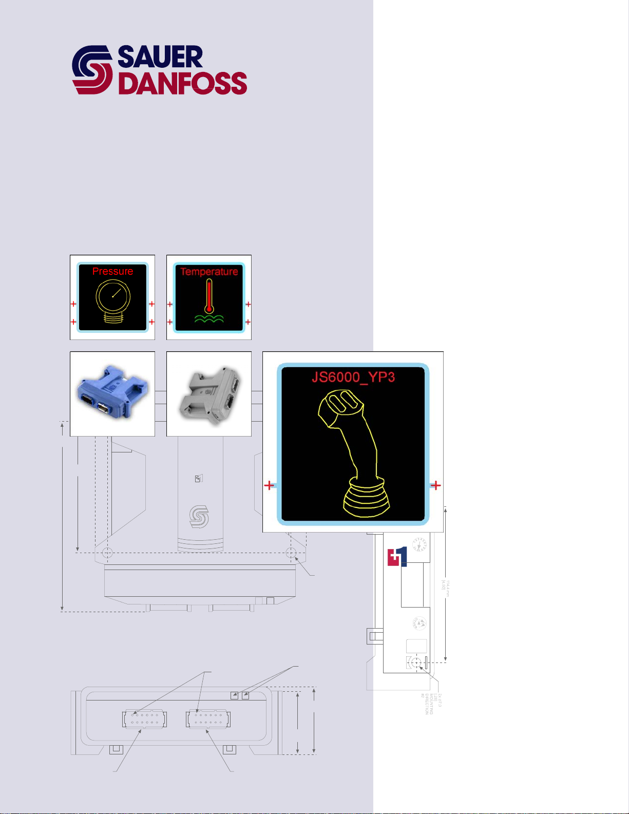
JS6000_YP3 Function Block
Overview
The JS6000_YP3 function block configures the output of a Sauer-Danfoss JS6000 YP3-Axis
joystick.
This joystick has:
• A base with a three-point y-axis.
• A grip with a P3 (proportional, three-point) rocker switch.
• Up to eight pushbuttons in its grip.
See:
• Connections and Signals Overview on page 6 for an overview of this function block’s
connections and signals.
• About the Name Space Feature on page 34 if you are using more than one of these
function blocks in your application.
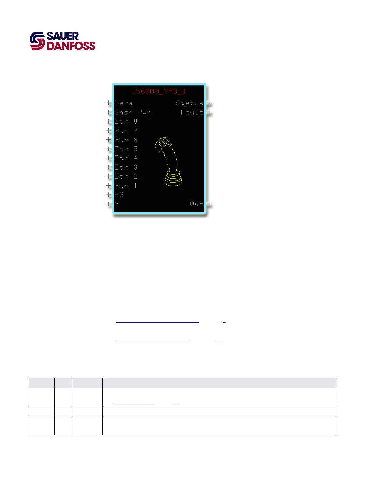
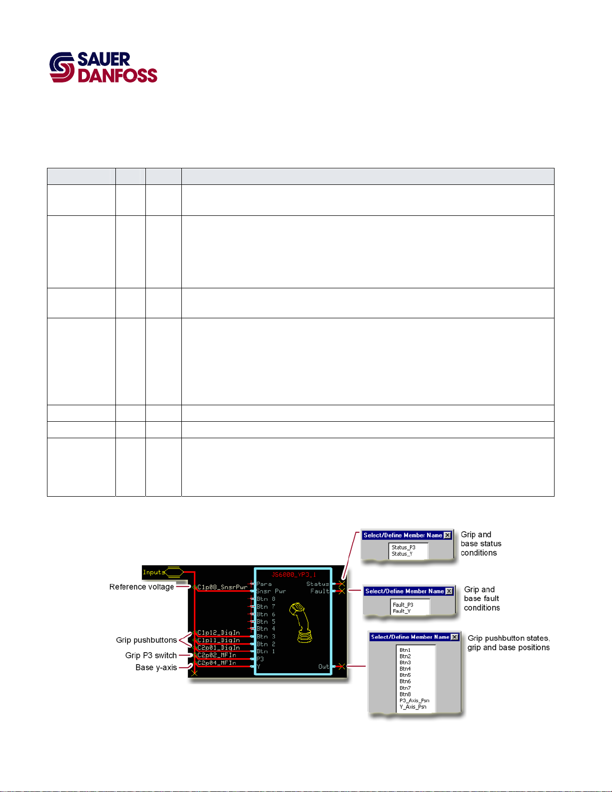
Inputs
JS6000_YP3 Function Block Inputs
Input Type Range Description
Para —— —— Allows common parameters to be applied to multiple joystick function blocks.
See About the Para Input on page 31 for more information.
Snsr Pwr —— 0–5260 mV Inputs the sensor power voltage (reference voltage) that the controller applies to the joystick’s sensor power pin.
Btn 1–8 BOOL —— Inputs the signals from the grip-mounted pushbuttons.
The number of pushbuttons on the joystick grip determines the number of connections that you need to make.
4
11015589
·
Rev BA · September 2011
Page 5

PLUS+1 Compliant JS6000 YP3-Axis Joystick Function Block
User Manual
JS6000_YP3 Function Block
JS6000_YP3 Function Block Inputs
Input Type Range Description
P3 —— 0–5260 mV The voltage input to the P3 pin indicates the position of the P3 switch on the joystick grip.
The default:
– CalLow calibration value for P3 is 10% of the SnsrPwr voltage. A P3 input at 10% of the SnsrPwr voltage
outputs a P3_Axis_Psn signal of -100%.
– CalMid calibration value for P3 is 50% of the SnsrPwr voltage. A P3 input at 50% of the SnsrPwr voltage
outputs a P3_Axis_Psn signal of 0%.
– CalHi calibration value for P3 is 90% of the SnsrPwr voltage. A P3 input at 90% of the SnsrPwr voltage
outputs a P3_Axis_Psn signal of 100%.
The P3 and Y inputs have identical configuration requirements and calibration values.
Y —— 0–5260 mV The voltage input to the Y pin indicates the position of the joystick base on its y-axis.
The default:
– CalLow calibration value for Y is 10% of the SnsrPwr voltage. A Y input at 10% of the SnsrPwr voltage
outputs a Y_Axis_Psn signal of -100%.
– CalMid calibration value for Y is 50% of the SnsrPwr voltage. A Y input at 50% of the SnsrPwr voltage
outputs a Y_Axis_Psn signal of 0%.
– CalHi calibration value for Y is 90% of the SnsrPwr voltage. A Y input at 90% of the SnsrPwr voltage outputs
a Y_Axis_Psn signal of 100%.
The P3 and Y inputs have identical configuration requirements and calibration values.
·
11015589
Rev BA
·
September 2011
5
Page 6
PLUS+1 Compliant JS6000 YP3-Axis Joystick Function Block
User Manual
JS6000_YP3 Function Block
Outputs
JS6000_YP3 Function Block Outputs
Output Type Range Description
Status Reports the function block’s status.
This output uses the standard bitwise scheme described in the Basic Function Blocks Library User’s Manual.
Status_P3,
Status_Y
Fault
Fault_P3,
Fault_Y
Out Outputs a bus with Btn and Psn signals.
Btn1–Btn8 BOOL —— Indicates the state of the pushbuttons in the grip.
P3_Axis_Psn,
Y_Axis_Psn
U16 —— Indicate the calibration and setup condition of the P3 and Y inputs.
– 0x0000 = Block is OK.
– 0x8001 = Block is not calibrated.
– 0x8002 = Block is partially calibrated.
– 0x8008 = Invalid setup/calibration.
Reports the function block’s faults.
This output uses the standard bitwise scheme described in the Basic Function Blocks Library User’s Manual.
U16 —— Indicate the operating condition of the P3 and Y inputs.
– 0x0000 = Block is OK.
– 0x8001 = Input value is too low.
– 0x8002 = Input value is too high.
– 0x8004 = Short circuit.
– 0x8008 = Open circuit.
S16 ±10000 Indicate the position of the joystick’s P3 switch and y-axis base.
– -10000 = -100.00%.
– 0 = 0%.
– +10000 = +100.00%.
Connections and Signals Overview
6
11015589
·
Rev BA
·
September 2011
Page 7
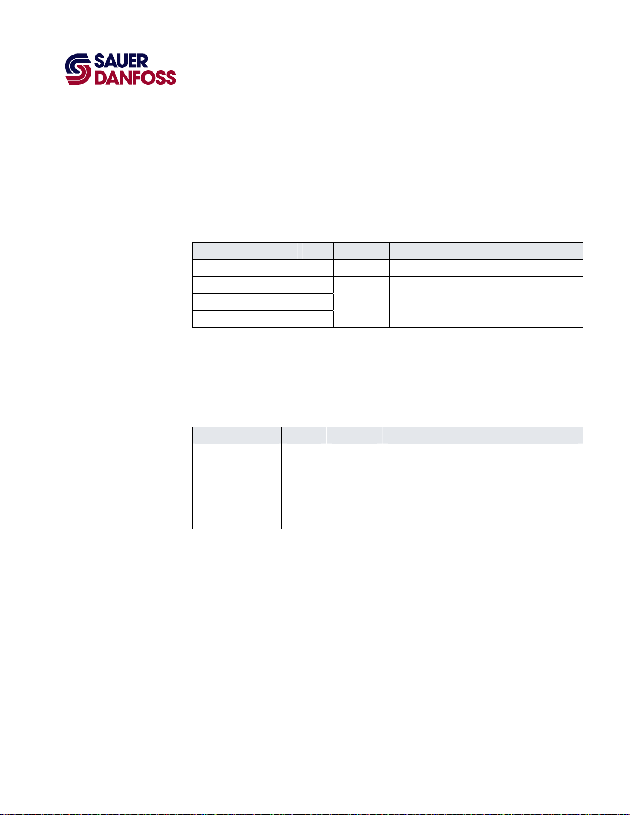
Status and Fault Logic
PLUS+1 Compliant JS6000 YP3-Axis Joystick Function Block
User Manual
JS6000_YP3 Function Block
The following table shows how:
• The Status output indicates the calibration conditions of the inputs.
• During calibration, the related Psn signal on the Out pin is zero.
Status Logic
Condition Status Psn Signal Comment
Block is OK. 0x0000 ±10000. Normal output of all Psn signals.
Block is not calibrated. 0x8001
Block is partially calibrated. 0x8002
Invalid setup/calibration. 0x8008
0*/±10000**.
*Calibration of an input sets its related Psn signal to
0.
**A valid input has a related Psn signal of ±10000.
The following table shows how:
• The Fault output indicates fault conditions.
• Any fault condition sets its related Psn signal on the Out pin to zero.
Fault Logic
Condition Fault Psn Signal Comment
Block is OK. 0x0000 ±10000. Normal output of both Psn signals.
Input value is too low. 0x8001
Input value is too high. 0x8002
0*/±10000**.
Short circuit. 0x8004
Open circuit. 0x8008
*An invalid input sets its related Psn signal to 0.
**A valid input has a related Psn signal of ±10000.
·
11015589
Rev BA
·
September 2011
7
Page 8
Configuration Settings
PLUS+1 Compliant JS6000 YP3-Axis Joystick Function Block
User Manual
JS6000_YP3 Function Block
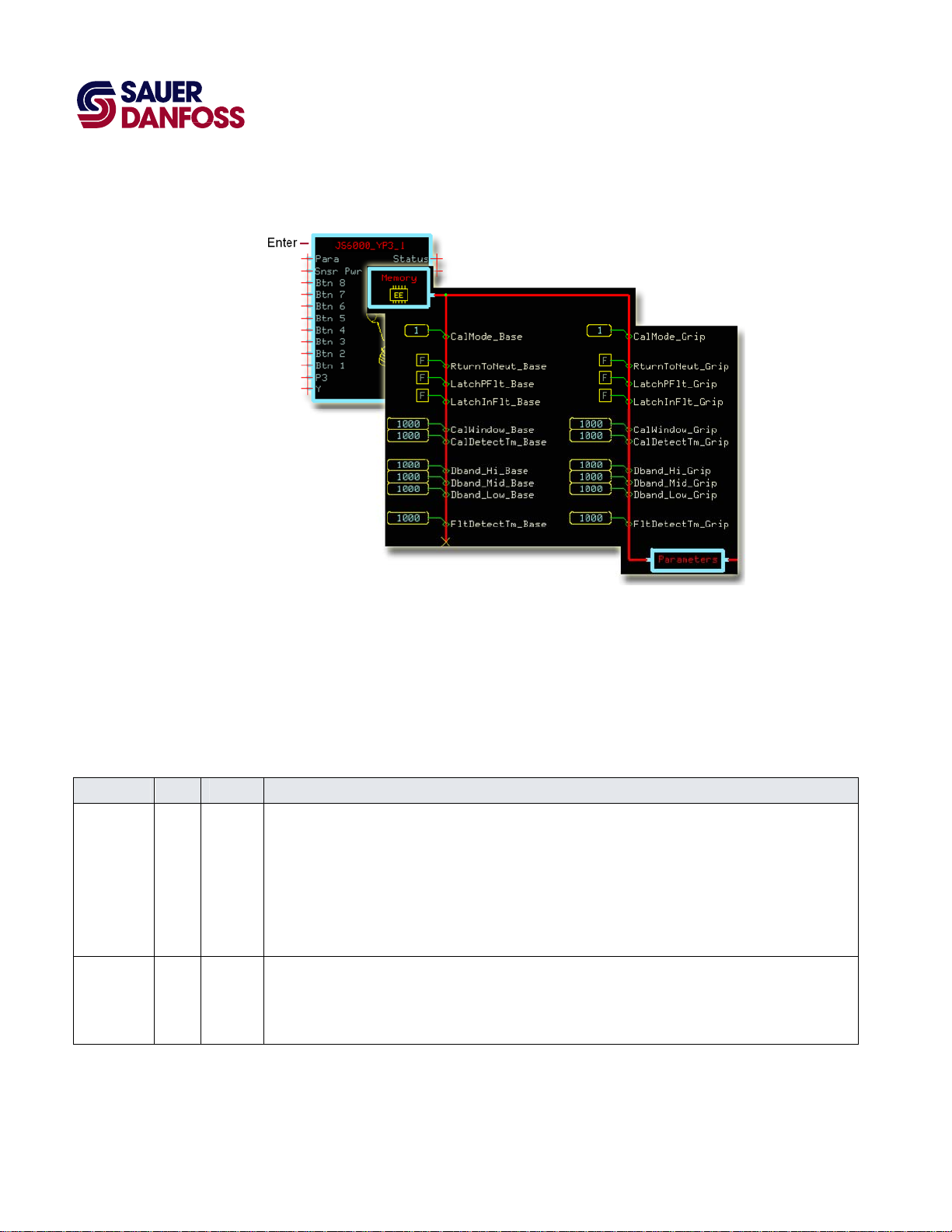
Enter the JS6000_YP3 page to change the JS6000_YP3 function block’s configuration
settings.
When working with configuration settings for PLUS+1 compliant joysticks, note that:
• Configuration inputs with a _Base suffix configure the joystick base.
• Configuration inputs with a _Grip suffix configure the joystick grip.
JS6000_YP3 Function Block Configuration Settings
Input Type Range Description
CalMode —— 0–3 Selects the CalMode (Calibration Mode) that sets the CalHi, CalMid, and CalLow values.
– 0—download values with the PLUS+1 GUIDE Service Tool program.
– 1—capture values using autocalibration or directly download values with the PLUS+1 GUIDE Service Tool
program.
In autocalibration, you operate the joystick and the block captures values that fall within defined windows.
– 2—the controller uses only the Default calibration values in the Memory page.
– 3—erases all calibration values.
RturnToNeut BOOL —— RturnToNeut (Return to Neutral) sets when the function block enables its Out signals after a controller startup,
calibration, or a Fault or Status condition.
– T—the block enables its Out signals only after all its inputs return to neutral.
– F—the block immediately enables its Out signals.
·
8
11015589
Rev BA
·
September 2011
Page 9
PLUS+1 Compliant JS6000 YP3-Axis Joystick Function Block
User Manual
JS6000_YP3 Function Block
JS6000_YP3 Function Block Configuration Settings
Input Type Range Description
LatchPFlt BOOL —— The function block sets a Status condition when it receives an invalid setup or calibration parameter.
The block disables the signal on the Out pin that is related to the abnormal parameter.
The LatchPFlt (Latch Parameter Fault) sets when the block enables the signal after the condition clears.
– T—the block enables the Out signal only after you repower the controller.
– F—the block immediately enables the Out signal.
LatchInFlt BOOL —— The function block sets a Fault condition when it receives an invalid input.
The block disables the Out signal that is related to the abnormal input.
The LatchInFlt (Latch Input Fault) sets when the block enables the signal after the condition clears.
– T—the block enables the Out signal only after you repower the controller.
– F—the block immediately enables the Out signal.
CalWindow —— 0–3000 The CalWindow (Calibration Window) sets the width of three calibration windows.
These windows center on the default CalHi, CalMid, and CalLow calibration values.
For more information, see About Calibration Windows and Default Calibration Values on page 11.
The default calibration values are set in the Memory page. They are the Default inputs to the three Non-Volatile
Memory Dynamic with Default components in this page.
During autocalibration, input voltages must be within these windows for the function block to capture them as
valid calibration values.
The CalWindow value is set as percentage of SnsrPwr.
1000 = 10.00%.
CalDetectTm —— 0–65535 The CalDetectTm (Calibration Detect Time) sets the time during autocalibration that input voltages must remain
in each calibration window for the function block to capture them as valid CalHi, CalMid, and CalLow calibration
values.
1000 = 1000 ms.
Dband_Hi —— 0–4999 The Dband_Hi (Deadband High) sets the width of an upper deadband.
An input voltage within this band produces a +100% output.
This deadband extends below the CalHi calibration value.
The function block sets the width of the Dband_Hi as a percentage of the difference between the CalHi and
CalMid calibration values.
For more information, see About Calibration Values and Deadbands on page 13.
1000 =10.00%.
·
11015589
Rev BA
·
September 2011
9
Page 10
PLUS+1 Compliant JS6000 YP3-Axis Joystick Function Block
User Manual
JS6000_YP3 Function Block
JS6000_YP3 Function Block Configuration Settings
Input Type Range Description
Dband_Mid —— 0–4999 The Dband_Mid (Deadband Middle) sets the width of a middle deadband.
An input voltage within this band produces a 0% output.
This deadband has an upper and lower half. The upper half extends above the CalMid calibration value. The
lower half extends below the CalMid calibration value.
The function block sets the width of the upper half of Dband Mid as a percentage of the difference between the
CalHi and CalMid calibration values.
The function block sets the width of the lower half of Dband Mid as a percentage of the difference between the
CalMid and CalLow calibration values.
For more information, see About Calibration Values and Deadbands on page 13.
1000 =10.00%.
Dband_Low —— 0–4999 The Dband_Low (Deadband Low) sets the width of a lower deadband.
This deadband extends above the CalLow calibration value.
An input voltage within this band produces a –100% output.
The function block sets the width of the Dband_Low as a percentage of the difference between the CalMid and
CalLow calibration values.
For more information, see About Calibration Values and Deadbands on page 13.
1000 = 10.00%.
FltDetectTm —— 0–65535 The FltDetectTm (Fault Detect Time) sets the time before an abnormal condition causes the function block to set
a Status or Fault condition.
1000 = 1000 ms.
10
11015589
·
Rev BA
·
September 2011
Page 11
PLUS+1 Compliant JS6000 YP3-Axis Joystick Function Block
User Manual
JS6000_YP3 Function Block
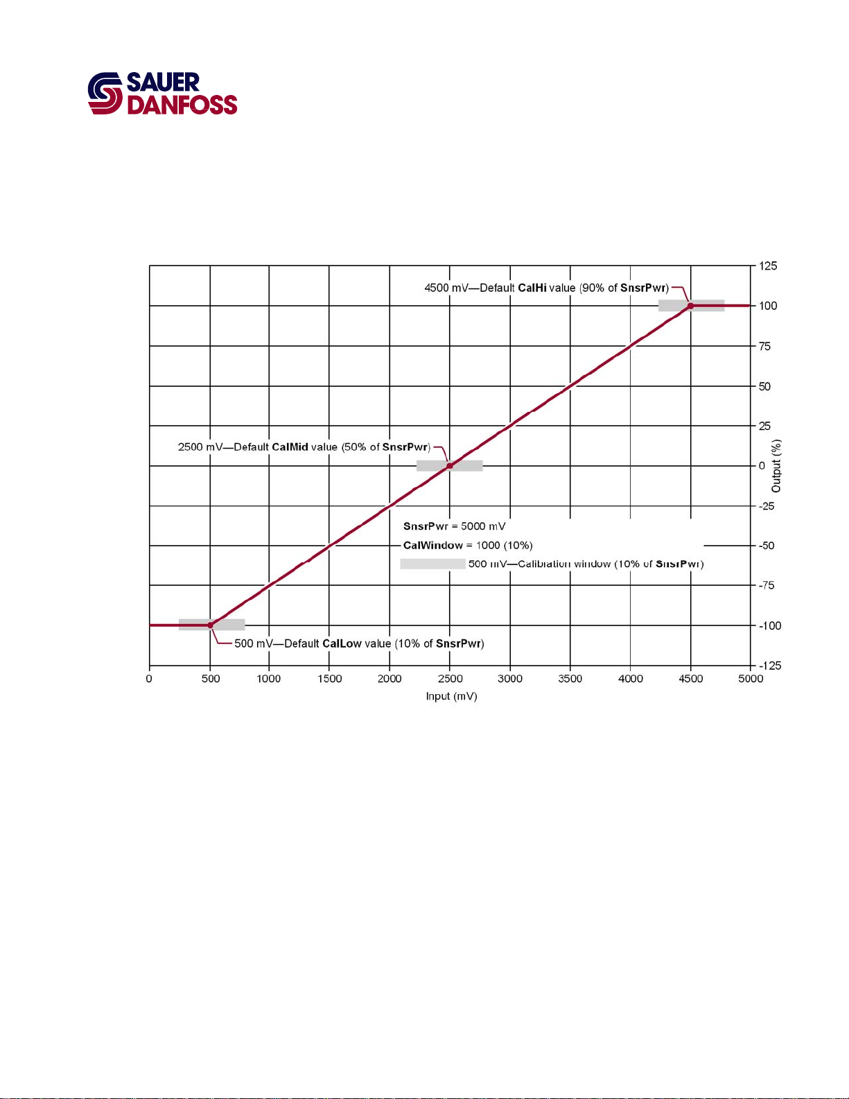
About Calibration Windows and Default Calibration Values
The following graph shows the relationship between the default calibration values and the
windows in which the function block captures calibration values during autocalibration.
• The JS6000_YP3 function block’s SnsrPwr is 5000 mV.
• The JS6000_YP3 function block’s default:
− CalLow calibration value is 1000, or 10% (500 mV) of SnsrPwr.
− CalMid calibration value is 5000, or 50% (2500 mV) of SnsrPwr.
− CalHi calibration value is 9000, or 90% (4500 mV) of SnsrPwr.
• The JS6000_YP3 function block’s CalWindow (Calibration window) is 1000, or 500
mV wide (10% of SnsrPwr).
(The Default values for CalLow, CalMid, and CalHi are set in the Memory page. The
CalWindow value is set in the JS6000_YP3 page.)
• The 500 mV wide calibration windows center on the Default values for CalLow,
CalMid, and CalHi.
·
11015589
Rev BA
·
September 2011
11
Page 12

PLUS+1 Compliant JS6000 YP3-Axis Joystick Function Block
User Manual
JS6000_YP3 Function Block
• During autocalibration, an input voltage must be between:
− 250–750 mV to be captured as a CalLow calibration value.
− 2250–2750 mV to be captured as CalMid calibration value.
− 4250–4750 mV to be captured as a CalHi calibration value.
12
11015589
·
Rev BA
·
September 2011
Page 13

PLUS+1 Compliant JS6000 YP3-Axis Joystick Function Block
User Manual
JS6000_YP3 Function Block
About Calibration Values and Deadbands
The following graph shows the:
• Formulas used by the function block to calculate high, middle, and low deadband
width.
• Relationship between the calibration values captured during autocalibration and the
width of the deadbands.
• During autocalibration, the JS6000_YP3 function block captured the:
− CalLo calibration value at 700 mV.
− CalMid calibration value at 2300 mV.
− CalHi calibration value at 4700 mV.
·
11015589
Rev BA
·
September 2011
13
Page 14

PLUS+1 Compliant JS6000 YP3-Axis Joystick Function Block
User Manual
JS6000_YP3 Function Block
• An input voltage that falls within the:
− Dband_Low deadband produces a -100% output from the function block.
− Dband_Mid deadbands produces a 0% output from the function block.
− Dband_Hi deadband produces a +100% output from the function block.
14
11015589
·
Rev BA
·
September 2011
Page 15

PLUS+1 Compliant JS6000 YP3-Axis Joystick Function Block
User Manual
JS6000_YP3 Function Block
MC Controller—Input Configuration
If you have an SC controller, see SC Controller—Input Configuration on page 18.
You can route the voltage needed by a joystick input though:
• A MFIn (Multifunction Input) on your controller.
• An AnIn (Analog Input) on your controller.
• A DigAn (Digital/Analog input) on your controller.
You must configure the input that you use to accept a voltage input.
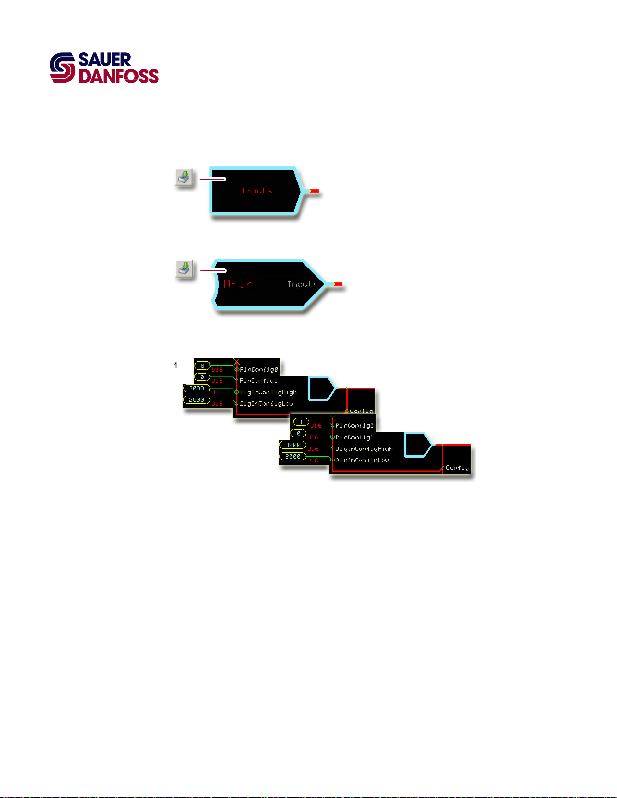
MC Controller—How to Configure a MFIn
1. In the GUIDE template, enter the Inputs page.
2. Enter the MFIn page that routes voltage to the input.
3. Delete the route as shown in the preceding figure.
·
11015589
Rev BA
·
September 2011
15
Page 16

PLUS+1 Compliant JS6000 YP3-Axis Joystick Function Block
User Manual
JS6000_YP3 Function Block
MC Controller—How to Configure an AnIn
1. In the GUIDE template, enter the Inputs page.
2. Enter the AnIn page that routes voltage to the input.
16
3. Delete the route as shown in the preceding figure.
·
11015589
Rev BA
·
September 2011
Page 17

PLUS+1 Compliant JS6000 YP3-Axis Joystick Function Block
User Manual
JS6000_YP3 Function Block
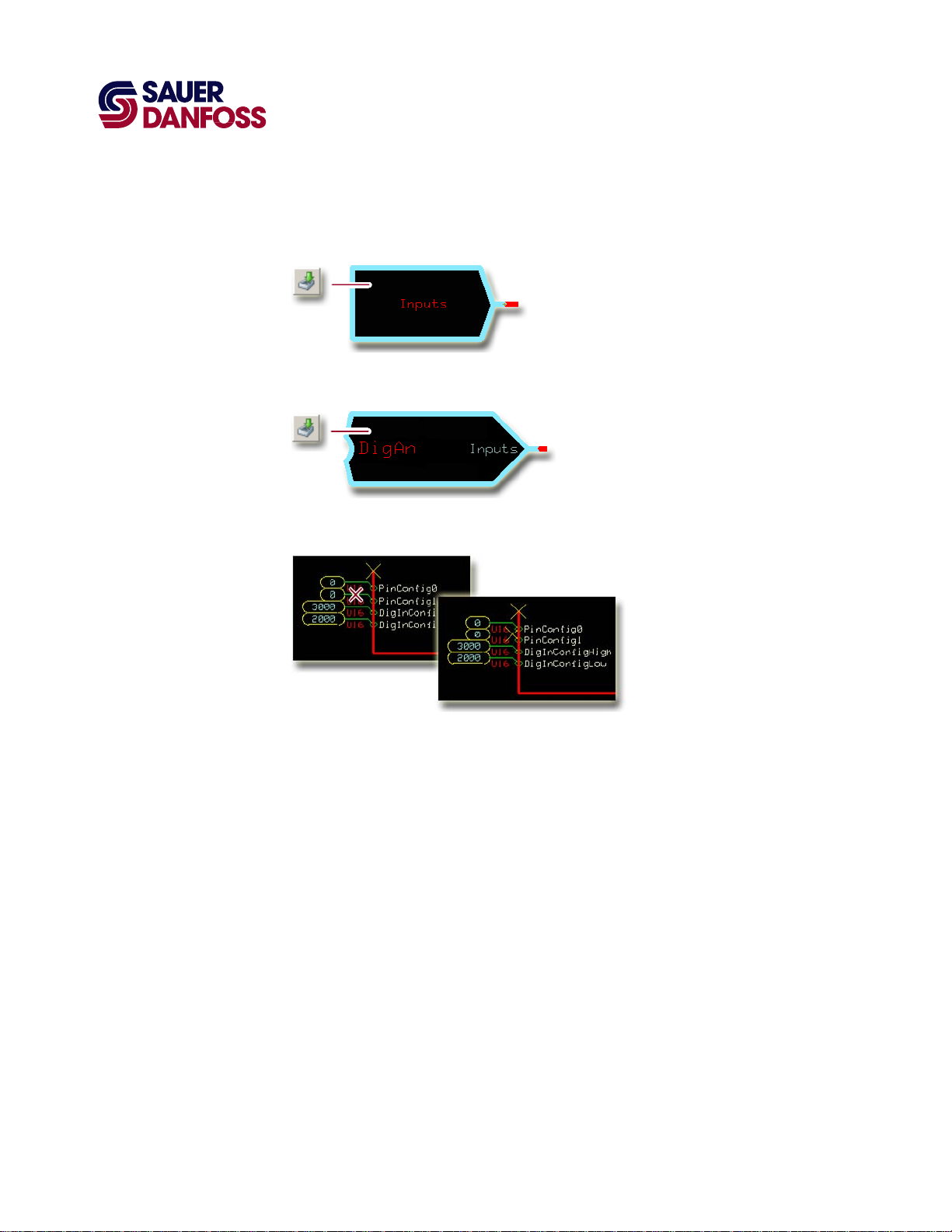
MC Controller—How to Configure a DigAn
1. In the GUIDE template, enter the Inputs page.
2. Enter the DigAn page that routes voltage to the input.
3. Delete the route as shown in the preceding figure.
·
11015589
Rev BA
·
September 2011
17
Page 18

PLUS+1 Compliant JS6000 YP3-Axis Joystick Function Block
User Manual
JS6000_YP3 Function Block
SC Controller—Input Configuration
If you have an MC controller, see MC Controller—Input Configuration on page 15.
You can route the voltage needed by this a joystick input though:
• A MFIn (Multifunction Input) on your controller.
• A DigAn (Digital/Analog) input on your controller.
You must configure the input that you use to accept a voltage input.
SC Controller—How to Configure a MFIn
1. In the GUIDE template, enter the Inputs page.
2. Enter the MFIn page that routes voltage to the input.
3. Delete the routes as shown in the preceding figure.
18
11015589
·
Rev BA
·
September 2011
Page 19
PLUS+1 Compliant JS6000 YP3-Axis Joystick Function Block
User Manual
JS6000_YP3 Function Block
SC Controller—How to Configure a DigAn
1. In the GUIDE template, enter the Inputs page.
2. Enter the DigAn page that routes voltage to the input.
3. Delete the routes as shown in the preceding figure.
·
11015589
Rev BA
·
September 2011
19
Page 20

About Pushbutton Wiring
PLUS+1 Compliant JS6000 YP3-Axis Joystick Function Block
User Manual
JS6000_YP3 Function Block
A pushbutton input can be wired to:
• +5 VDC common sensor power.
• Common sensor power ground.
Pushbutton input wired to +5 VDC common sensor power
Pushbutton input wired to common sensor power ground
20
11015589
·
Rev BA
·
September 2011
Page 21

PLUS+1 Compliant JS6000 YP3-Axis Joystick Function Block
User Manual
JS6000_YP3 Function Block
MC Controller—Pushbutton Input Configuration
You can route a pushbutton input to a Btn pin on the function block through:
• A DigIn on your controller.
• An MFIn on your controller.
• A DigAn on your controller.
You must configure the input that you use to accept a pushbutton input.
MC Controller—How to Configure a DigIn for a +5 VDC Activated Pushbutton Input
T By default, a DigIn on a typical PLUS+1 GUIDE template requires no configuration
changes to accept an input from a pushbutton wired to +5 VDC common sensor power.
However, it is a good idea to verify the configuration of a DigIn.
1. In the GUIDE template, enter the Inputs page.
2. Enter the DigIn page that configures the pushbutton input.
3. Make sure that the PinConfig value is 2.
·
11015589
Rev BA
·
September 2011
21
Page 22

PLUS+1 Compliant JS6000 YP3-Axis Joystick Function Block
User Manual
JS6000_YP3 Function Block
MC Controller—How to Configure a DigIn for a Ground-Activated Pushbutton Input
1. In the GUIDE template, enter the Inputs page.
2. Enter the DigIn page that configures the pushbutton input.
3. Change the PinConfig value to 1.
22
11015589
·
Rev BA
·
September 2011
Page 23

PLUS+1 Compliant JS6000 YP3-Axis Joystick Function Block
User Manual
JS6000_YP3 Function Block
MC Controller—How to Configure a DigAn for a +5 VDC Activated Pushbutton Input
1. In the GUIDE template, enter the Inputs page.
2. Enter the DigAn page that configures the pushbutton input.
3. Change the PinConfig0 value to 2.
·
11015589
Rev BA
·
September 2011
23
Page 24

PLUS+1 Compliant JS6000 YP3-Axis Joystick Function Block
User Manual
JS6000_YP3 Function Block
MC Controller—How to Configure a DigAn for a Ground-Activated Pushbutton Input
1. In the GUIDE template, enter the Inputs page.
2. Enter the DigAn page that configures the pushbutton input.
24
3. Change the PinConfig value to 1.
·
11015589
Rev BA
·
September 2011
Page 25

PLUS+1 Compliant JS6000 YP3-Axis Joystick Function Block
User Manual
JS6000_YP3 Function Block
MC Controller—How to Configure a MFIn for a +5 VDC Activated Pushbutton Input
1. In the GUIDE template, enter the Inputs page.
2. Enter the MFIn page that configures the pushbutton input.
3. Change the PinConfig0 value to 2.
·
11015589
Rev BA
·
September 2011
25
Page 26
PLUS+1 Compliant JS6000 YP3-Axis Joystick Function Block
User Manual
JS6000_YP3 Function Block
MC Controller—How to Configure a MFIn for a Ground-Activated Pushbutton Input
1. In the GUIDE template, enter the Inputs page.
2. Enter the MFIn page that configures the pushbutton input.
26
3. Change the PinConfig0 value from 0 to 1.
·
11015589
Rev BA
·
September 2011
Page 27

PLUS+1 Compliant JS6000 YP3-Axis Joystick Function Block
User Manual
JS6000_YP3 Function Block
SC Controller—Pushbutton Input Configuration
You can route a pushbutton input to a Btn pin on the function block through:
• A DigAn on your controller.
• An MFIn on your controller.
You must configure the input that you use to accept a pushbutton input.
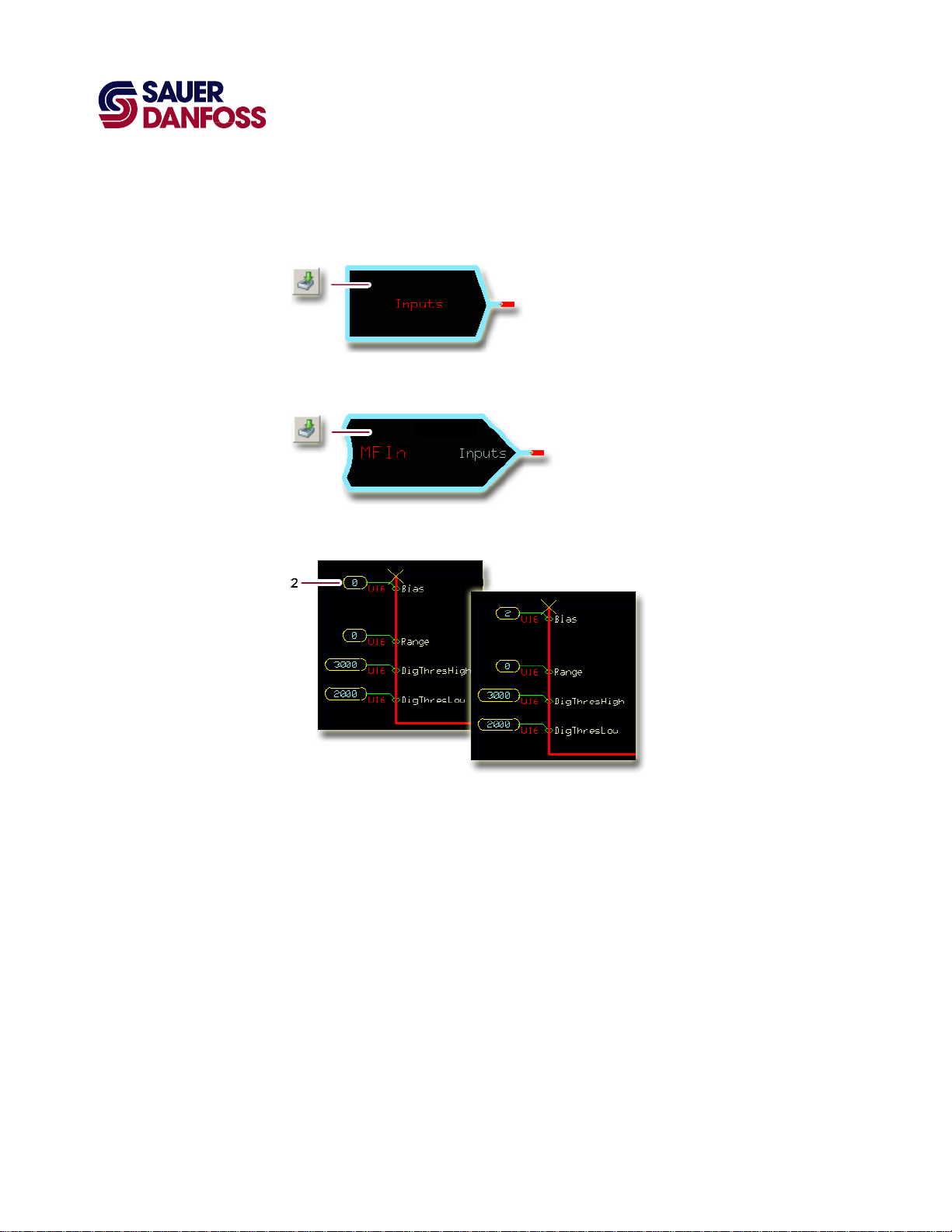
SC Controller—How to Configure a DigAn for a +5 VDC Activated Pushbutton Input
1. In the GUIDE template, enter the Inputs page.
2. Enter the DigAn page that configures the pushbutton input.
3. Change the Bias value to 2.
·
11015589
Rev BA
·
September 2011
27
Page 28

PLUS+1 Compliant JS6000 YP3-Axis Joystick Function Block
User Manual
JS6000_YP3 Function Block
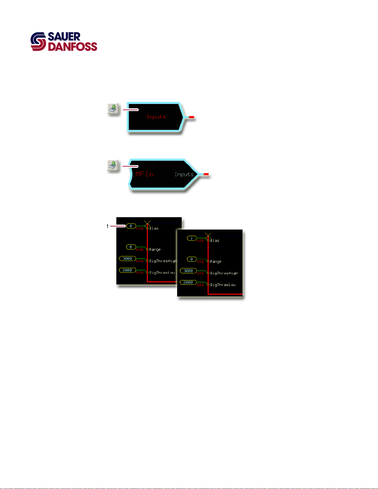
SC Controller—How to Configure a DigAn for a Ground-Activated Pushbutton Input
1. In the GUIDE template, enter the Inputs page.
2. Enter the DigAn page that configures the pushbutton input.
28
3. Change the Bias value to 1.
·
11015589
Rev BA
·
September 2011
Page 29
PLUS+1 Compliant JS6000 YP3-Axis Joystick Function Block
User Manual
JS6000_YP3 Function Block
SC Controller—How to Configure a MFIn for a +5 VDC Activated Pushbutton Input
1. In the GUIDE template, enter the Inputs page.
2. Enter the MFIn page that configures the pushbutton input.
3. Set the Bias value to 2.
·
11015589
Rev BA
·
September 2011
29
Page 30
PLUS+1 Compliant JS6000 YP3-Axis Joystick Function Block
User Manual
JS6000_YP3 Function Block
SC Controller—How to Configure a MFIn for a Ground-Activated Pushbutton Input
1. In the GUIDE template, enter the Inputs page.
2. Enter the MFIn page that configures the pushbutton input.
30
3. Set the Bias value to 1.
·
11015589
Rev BA
·
September 2011
Page 31
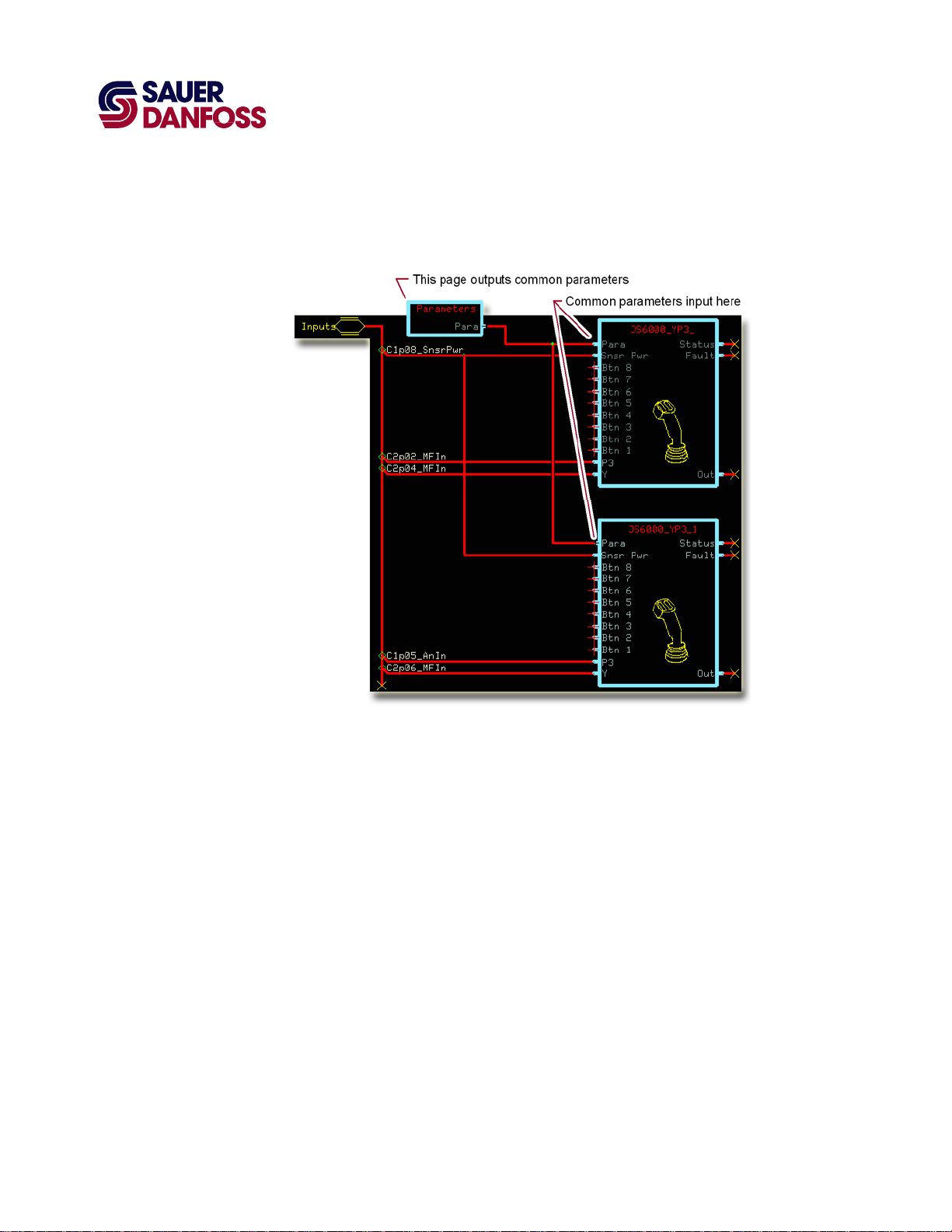
About the Para Input
PLUS+1 Compliant JS6000 YP3-Axis Joystick Function Block
User Manual
JS6000_YP3 Function Block
Use the Para input to apply a common set of parameters to multiple function blocks.
The preceding figure shows a Parameters page that outputs common, shared parameters
to identical function blocks.
·
11015589
Rev BA
·
September 2011
31
Page 32

PLUS+1 Compliant JS6000 YP3-Axis Joystick Function Block
User Manual
JS6000_YP3 Function Block
The preceding figure shows the contents of the Parameters page that applies the
common, shared parameters to the function blocks.
You create this Parameters page yourself. How you implement parameter sharing
determines the inputs, outputs, contents, and name of this page.
32
11015589
·
Rev BA
·
September 2011
Page 33

PLUS+1 Compliant JS6000 YP3-Axis Joystick Function Block
User Manual
JS6000_YP3 Function Block
The preceding figure shows the changes made to a JS6000_YP3 page to enable this page
to accept common parameters through its Para input.
·
11015589
Rev BA
·
September 2011
33
Page 34

PLUS+1 Compliant JS6000 YP3-Axis Joystick Function Block
User Manual
JS6000_YP3 Function Block
About the Name Space Feature
If you use this function block more than once in an application, you must change each
function block’s Name Space value to avoid compiler errors.
These function blocks allocate memory using memory names (“aliases”). Identical function
blocks have identical memory names. Identical memory names will cause a compiler error.
The Name Space value adds a unique prefix to each memory name to avoid memory
allocation errors.
34
How to Enter a Name Space Value
1. In the PLUS+1 GUIDE menu bar, click the Query/Change button.
2. Click the function block’s page name to display the Edit Page window.
3. In the Edit Page window, enter a meaningful Name Space value.
4. Press /.
5. Repeat these steps to enter unique Name Space values for other identical function
blocks.
·
11015589
Rev BA
·
September 2011
Page 35

PLUS+1 Compliant JS6000 YP3-Axis Joystick Function Block
User Manual
(This page is intentionally blank.)
Page 36

p
Products we offer:
• Bent Axis Motors
• Closed Circuit Axial Piston Pumps
and Motors
• Displays
• Electrohydraulic Power Steering
• Electrohydraulics
• Hydraulic Power Steering
• Integrated Systems
• Joysticks and Control Handles
• Microcontrollers and Software
• Open Circuit Axial Piston Pumps
• Orbital Motors
• PLUS+1™ GUIDE
• Proportional Valves
• Sensors
• Steering
Sauer-Danfoss is a global manufacturer and supplier of highquality hydraulic and electronic components. We specialize in
providing state-of-the-art technology and solutions that excel in
the harsh operating conditions of the mobile off-highway market.
Building on our extensive applications expertise, we work closely
with our customers to ensure exceptional performance for a broad
range of off-highway vehicles.
We help OEMs around the world speed up system development,
reduce costs and bring vehicles to market faster.
Sauer-Danfoss—Your Strongest Partner in Mobile Hydraulics.
Go to www.sauer-danfoss.com for further product information.
Wherever off-highway vehicles are at work, so is Sauer-Danfoss.
We offer expert worldwide support for our customers, ensuring the
best possible solutions for outstanding performance. And with an
extensive network of Global Service Partners, we also provide
comprehensive global service for all of our components.
Transit Mixer Drives
•
Members of the Sauer-Danfoss Group:
Comatrol
www.comatrol.com
Schwarzmüller-Inverter
www.schwarzmueller-inverter.com
Turolla
www.turollaocg.com
Hydro-Gear
www.hydro-gear.com
Sauer-Danfoss-Daikin
www.sauer-danfoss-daikin.com
Please contact the Sauer-Danfoss re
Local address:
Sauer-Danfoss Inc.
3500 Annapolis Lane North
Minneapolis, MN 55447, USA
Phone: +1 763 509-2000
Fax: +1 763 559-5769
Sauer-Danfoss (US) Company
2800 East 13th Street
Ames, IA 50010, USA
Phone: +1 515 239-6000
Fax: +1 515 239-6618
Sauer-Danfoss GmbH & Co. OHG
Postfach 2460, D-24531 Neumünster
Krokamp 35, D-24539 Neumünster,
Germany
Phone: +49 4321 871-0
Fax: +49 4321 871 122
resentative nearest you.
Sauer-Danfoss ApS
DK-6430 Nordborg, Denmark
Phone: +45 7488 4444
Fax: +45 7488 4400
Sauer-Danfoss-Daikin LTD
Shin-Osaka TERASAKI 3rd Bldg. 6F
1-5-28 Nishimiyahara, Yodogawa-ku
Osaka 532-0004, Japan
Phone: +81 6 6395 6066
Fax: +81 6 6395 8585
11015589 ● Rev BA ● September 2011
www.sauer-danfoss.com
 Loading...