

Page 1
PLUS+1™ GUIDE
Software
PLUS+1 Compliant JS6000 Joystick with External Analog Inputs Function Block User Manual
TEMP JOYSTICK
142.0 mm
[5.59]
97.0 mm
[3.82]
VALV E
PRESSURE
158.2 mm
6.23
144.5 mm
5.69
PIN #1
INDICATED
2x 25.2 mm
[1.0]
2x ∅7.0
[.28]
MOUNTING
DIRECTION
#2
LED INDICATO R
LIGHTS
TM
COMPLIANT
CONNECTOR MATES
WITH DEUTCH
CONNECTOR #D TM-06-125A
51.6 mm
47.1 mm
[1.85]
[2.03]
1
12
6
7
1
6
12
7
CONNECTOR MATES
WITH DEUTCH
CONNECTOR #DTM-06-125A
Page 2
PLUS+1 Compliant JS6000 Joystick with External Analog Inputs
Function Block User Manual
About this Manual
Organization
and Headings
To help you quickly find information in this manual, the material is divided into sections,
topics, subtopics, and details, with descriptive headings set in red type. Section titles
appear at the top of every page in large red type.
In the PDF version of this document, clicking an item underlined in blue italic type
you to the referenced page in the document.
Special Text Formatting Controls and indicators are set in bold black type.
Table of Contents
A Table of Contents (TOC) appears on the next page. In the PDF version of this document,
the TOC entries are hyperlinked.
Revision History
Revision Date Comment
Rev A April 2007
Rev AB May 2010
Rev AC July 2010
jumps
©2010 Sauer-Danfoss. All rights reserved.
Sauer-Danfoss accepts no responsibility for possible errors in catalogs, brochures and other printed material.
Sauer-Danfoss reserves the right to alter its products without prior notice. This also applies to products already
ordered provided that such alterations can be made without affecting agreed specifications.
All trademarks in this material are properties of their respective owners.
PLUS+1, GUIDE, and Sauer-Danfoss are trademarks of the Sauer-Danfoss Group. The PLUS+1 GUIDE, PLUS+1
Compliant, and Sauer-Danfoss logotypes are trademarks of the Sauer-Danfoss Group.
2
11026746 · Rev AC · July 2010
Page 3

PLUS+1 Compliant JS6000 Joystick with External Analog Inputs
Function Block User Manual
Contents
JS6000_CAN_w_An Function Block.......................................................................................................... 4
Overview ....................................................................................................................................................4
Inputs........................................................................................................................................................... 4
Outputs....................................................................................................................................................... 5
Status and Fault Logic..........................................................................................................................10
Boolean Output Signals ..............................................................................................................10
Proportional Output Signals......................................................................................................10
Connections and Signals Overview.................................................................................................11
Configuration of Input and Output Buses ....................................................................................11
11026746 z Rev AC z July 2010
3
Page 4
Overview
PLUS+1 Compliant JS6000 Joystick with External Analog Inputs
Function Block User Manual
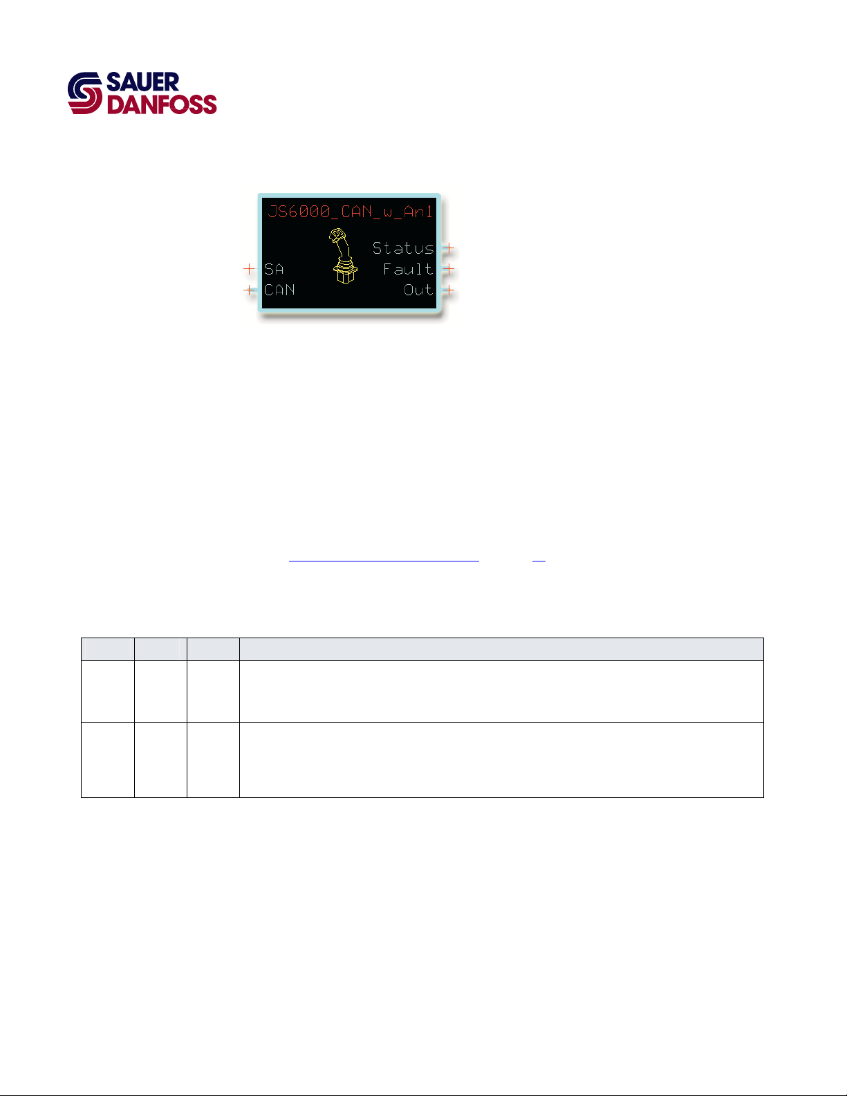
JS6000_CAN_w_An Function Block
6000_CAN_w_An function block configures the output of a Sauer-Danfoss JS6000
The JS
Joystick with external analog inputs.
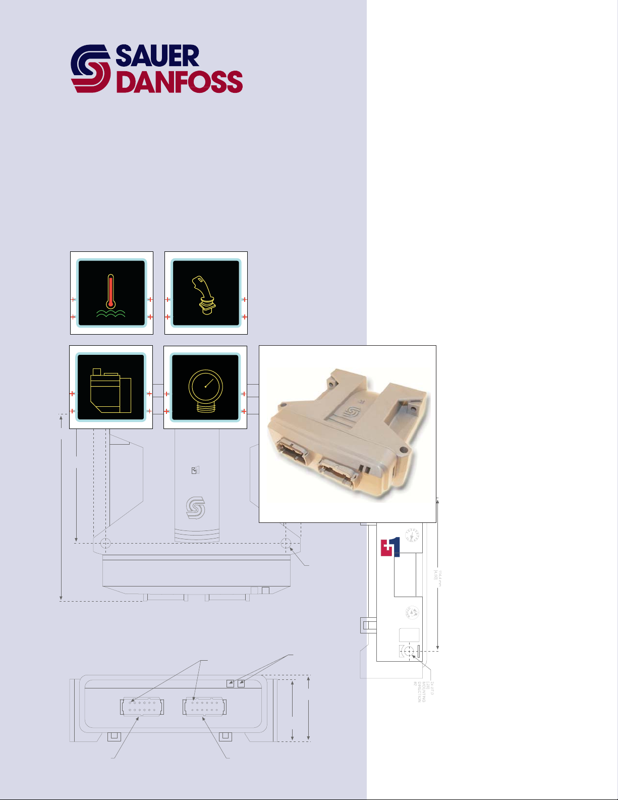
The JS6000 Joystick with external analog inputs is a highly configurable joystick that has:
• A joystick base with a single three-point y axis or with three-point x and y axes.
• Up to two grip-mounted proportional three-point rocker switches.
• Up to five grip-mounted push-buttons switches.
• External analog inputs.
Also see Connections and Signals Overview
on page 11.
Inputs
JS6000_
Input Type Range Description
SA U8 0-253 In the GUIDE template, route a signal to the SA (Source Address) input.
CAN —— —— In the GUIDE template, identify the CAN bus that inputs CAN messages from the joystick. Route this bus to the
CAN_w_An Function Block Inputs
Set the signal to specify the source address of the joystick.
All source addresses on the same CAN bus must be different. Do not use the same address twice.
CAN input.
CAN messages sent from the joystick to the function block contain information about the availability of joystick
inputs, joystick input faults, and joystick commands.
4
11026746 z Rev AC z July 2010
Page 5

PLUS+1 Compliant JS6000 Joystick with External Analog Inputs
Function Block User Manual
JS6000_CAN_w_An Function Block
Outputs
JS6000_CAN_w_An Function Block Outputs
Output Type Range Description
Status —— —— Outputs a bus that contains the status signals listed below.
Btn1_NA–Btn12_NA BOOL —— Indicates if an input is available from a grip-mounted push button switch.
T = Not available.
F = Available.
T_Det_NA BOOL —— Indicates if an input from a detent switch on the joystick’s rotational (theta) axis is
available.
T = Not available.
F = Available.
T_NA BOOL —— Indicates if an input from a rotational (theta) axis is available.
T = Not available.
F = Available.
XGrp_Det_NA BOOL —— Indicates if an input from a grip-mounted, x-axis detent switch is available.
T = Not available.
F = Available.
XGrp_NA BOOL —— Indicates if an input from a grip-mounted, x-axis, proportional switch is available.
T = Not available.
F = Available.
X_Det_NA BOOL —— Indicates if an input from a grip-mounted, x-axis, detent switch is available.
T = Not available.
F = Available.
X_NA BOOL —— Indicates if an input from the joystick’s x axis is available.
T = Not available.
F = Available.
YGrp_Det_NA BOOL —— Indicates if an input from a grip-mounted, y-axis detent switch is available.
T = Not available.
F = Available.
YGrp_NA BOOL —— Indicates if an input from a grip-mounted, y-axis, proportional switch is available.
T = Not available.
F = Available.
Y_Det_NA BOOL —— Indicates if an input from a grip-mounted, y-axis, detent switch is available.
T = Not available.
F = Available.
Y_NA BOOL —— Indicates if an input from the joystick’s y axis is available.
T = Not available.
F = Available.
11026746 z Rev AC z July 2010
5
Page 6

PLUS+1 Compliant JS6000 Joystick with External Analog Inputs
Function Block User Manual
JS6000_CAN_w_An Function Block
JS6000_CAN_w_An Function Block Outputs
Output Type Range Description
Fault —— —— Outputs a bus that contains the fault signals listed below.
Btn1_Flt–Btn12_Flt BOOL —— Indicates if the input from a grip-mounted push-button switch has a fault.
T = Fault.
F = No fault.
T_Det_Flt BOOL —— Indicates if the input from a detent switch on the joystick’s rotational (theta) axis has a
fault.
T = Fault.
F = No fault.
T_Flt BOOL —— Indicates if the input from the joystick’s rotational (theta) axis has a fault.
T = Fault.
F = No fault.
TimeOut_BJM BOOL —— Indicates if the function block receives a CAN Rx_BJM (Receive Basic Joystick Message)
within a 100 ms timeout limit.
This message reports joystick x-axis and y-axis positions as well as the state of grip-
mounted button switches.
When this signal is T, the function block sets all Out signals associated with the Rx_BJM
message to either 0 or F. It sets all Fault signals associated with the Rx_BJM message to
T.
When this signal becomes F again, the function block enables all Out signals associated
with the Rx_BJM message. It resets all Fault signals associated with the Rx_BJM
message to F.
T = Message not received within 100 ms limit.
F = Message received within 100 ms limit.
TimeOut_BJM3 BOOL —— Indicates if the function block receives a CAN Rx_BJM3 (Receive Basic Joystick Message
Three) within a 100 ms timeout limit.
This message reports joystick x-axis and y-axis positions as well as the state of grip-
mounted button switches.
When this signal is T, the function block sets all Out signals associated with the
Rx_BJM3 message to either 0 or F. It sets all Fault signals associated with the Rx_BJM3
message to T.
When this signal becomes F again, the function block enables all Out signals associated
with the Rx_BJM3 message. It resets all Fault signals associated with the Rx_BJM3
message to F.
T = Message not received within 100 ms limit.
F = Message received within 100 ms limit.
6
11026746 z Rev AC z July 2010
Page 7

PLUS+1 Compliant JS6000 Joystick with External Analog Inputs
Function Block User Manual
JS6000_CAN_w_An Function Block
JS6000_CAN_w_An Function Block Outputs
Output Type Range Description
TimeOut_EJM BOOL —— Indicates if the function block receives a CAN Rx_EJM (Receive Extended Joystick
Message) within a 100 ms timeout limit.
This message reports the position of grip-mounted proportional switches.
When this signal is T, the function block sets all Out signals associated with the Rx_EJM
message to either 0 or F. It sets all Fault signals associated with the Rx_EJM message to
T.
When this signal becomes F again, the function block enables all Out signals associated
with the Rx_EJM message. It resets all Fault signals associated with the Rx_EJM
message to F.
T = Message not received within 100 ms limit.
F = Message received within 100 ms limit.
TimeOut_EJM3 BOOL —— Indicates if the function block receives a CAN Rx_EJM3 (Receive Extended Joystick
Message Three) within a 100 ms timeout limit.
This message reports the position of grip-mounted proportional switches.
When this signal is T, the function block sets all Out signals associated with the
Rx_EJM3 message to either 0 or F. It sets all Fault signals associated with the Rx_EJM3
message to T.
When this signal becomes F again, the function block enables all Out signals associated
with the Rx_EJM3 message. It resets all Fault signals associated with the Rx_EJM3
message to F.
T = Message not received within 100 ms limit.
F = Message received within 100 ms limit.
XGrp_Det_Flt BOOL —— Indicates if the input from a grip-mounted, x-axis detent switch has a fault.
T = Fault.
F = No fault.
XGrp_Flt BOOL —— Indicates if the input from a grip-mounted, y-axis proportional switch has a fault.
T = Fault.
F = No fault.
X_Det_Flt BOOL —— Indicates if the input from a detent switch on the joystick’s x axis has a fault.
T = Fault.
F = No fault.
X_Flt BOOL —— Indicates if the input from the joystick’s x axis has a fault.
T = Fault.
F = No fault.
YGrp_Det_Flt BOOL —— Indicates if the input from a detent switch on the joystick’s y axis has a fault.
T = Fault.
F = No fault.
11026746 z Rev AC z July 2010
7
Page 8

PLUS+1 Compliant JS6000 Joystick with External Analog Inputs
Function Block User Manual
JS6000_CAN_w_An Function Block
JS6000_CAN_w_An Function Block Outputs
Output Type Range Description
YGrp_Flt BOOL —— Indicates if the input from a grip-mounted, y-axis proportional switch has a fault.
T = Fault.
F = No fault.
Y_Det_Flt BOOL —— Indicates if the input from a detent switch on the joystick’s y axis has a fault.
T = Fault.
F = No fault.
Y_Flt BOOL —— Indicates if the input from the joystick’s y axis has a fault.
T = Fault.
F = No fault.
Out —— —— Outputs a bus that contains the command signals listed below. These signals indicate
the position of each joystick axis and the state of push-button and detent switches.
SnsrPwr.Volt,
DigIn.DigIn,
AnDigIn.Volt, and
AnDigIn.DigIn
Btn1–Btn12 BOOL —— Indicates the states of grip-mounted push-button switches.
Rx_BJM BOOL —— Indicates when the function block receives a CAN Rx_BJM (Receive Basic Joystick
Rx_EJM BOOL —— Indicates when the function block receives a CAN Rx_EMJ (Receive Extended Joystick
T_Axis_Det BOOL —— Indicates the state of a detent switch on the joystick’s rotational (theta) axis.
T_Axis_Psn S16 –10000 to +10000 Indicates the position of the joystick’s rotational (theta) axis.
—— —— Indicates the states of the joystick’s external inputs and sensor power supply.
T = Closed.
F = Open.
Message).
This message reports joystick x-axis and y-axis positions as well as the state of grip-
mounted button switches have been updated.
T = Message received.
F = Message not received.
Message).
This message reports the position of grip-mounted proportional switches have been
updated.
T = Message received.
F = Message not received.
T = Closed.
F = Open.
–10000 = –100%
+10000 = +100%
8
11026746 z Rev AC z July 2010
Page 9

PLUS+1 Compliant JS6000 Joystick with External Analog Inputs
Function Block User Manual
JS6000_CAN_w_An Function Block
JS6000_CAN_w_An Function Block Outputs
Output Type Range Description
XGrp_Det BOOL —— Indicates the state of a detent switch on a grip-mounted, x-axis proportional switch.
T = Closed.
F = Open.
X_Grp_Psn S16 –10000 to +10000 Indicates the position of a grip-mounted, x-axis proportional switch.
–10000 = –100%
+10000 = +100%
X_Axis_Det BOOL —— Indicates the state of a detent switch on the joystick’s x-axis.
T = Closed.
F = Open.
X_Axis_Psn S16 –10000 to +10000 Indicates the position of the joystick’s x axis.
–10000 = –100%
+10000 = +100%
YGrp_Det BOOL —— Indicates the state of a detent switch on a grip-mounted, y-axis proportional switch.
T = Closed.
F = Open.
YGrp_Psn S16 –10000 to +10000 Indicates the position of a grip-mounted, y-axis proportional switch.
–10000 = –100%
+10000 = +100%
Y_Axis_Det BOOL —— Indicates the state of a detent switch on the joystick’s y-axis.
T = Closed.
F = Open.
Y_Axis_Psn S16 –10000 to +10000 Indicates the position of the joystick’s y axis.
–10000 = –100%
+10000 = +100%
11026746 z Rev AC z July 2010
9
Page 10

PLUS+1 Compliant JS6000 Joystick with External Analog Inputs
Function Block User Manual
JS6000_CAN_w_An Function Block
Status and Fault Logic
Boolean Output Signals
ollowing table shows how the changing states of the Status and Fault signals affect
The f
the value of Boolean output signals.
Status and Fault Logic—Boolean Output Signals
Output Signal Status Signal State Fault Signal State Output Signal Value
Btn1–Btn12, Rx_BJM, Rx_EJM, T_Axis_Det, XGrp_Det, X_Axis_Det,
YGrp_Det, Y_Axis_Det
For example:
• As long as the Status signal and the Fault signal for the Btn1 input are both F, the
Btn1 output signal can be either T or F.
F F T or F
T T F
T F F
F T F
• As soon as either the Status signal or the Fault signal for the Btn1 input becomes T,
the Btn1 output signal goes to and stays F.
• When the Status signal and the Fault signal for the Btn1 input are again both F, the
Btn1 output signal returns to its normal T or F operation.
Proportional Output Signals
The f
ollowing table shows how the changing states of the Status and Fault signals affect
the value of proportional output signals.
Status and Fault Logic—Proportional Output Signals
Output Signal Status Signal State Fault Signal State Output Signal Value
T_Axis_Psn, X_Grp_Psn, X_Axis_Psn, YGrp_Psn, Y_Axis_Psn
F F –10000 to +10000
T T 0
T F 0
F T 0
For example:
• As long as the Status signal and the Fault signal for the T_Axis_Psn input are both F,
the T_Axis_Psn output signal ranges from –10000 to +10000.
• As soon as either the Status signal or the Fault signal for the T_Axis_Psn input
becomes T, the T_Axis_Psn output signal goes to and stays at 0.
10
• When the Status signal and the Fault signal for the T_Axis_Psn input are again both
F, the T_Axis_Psn output signal returns to its normal –10000 to +10000 operation.
11026746 z Rev AC z July 2010
Page 11

PLUS+1 Compliant JS6000 Joystick with External Analog Inputs
Function Block User Manual
JS6000_CAN_w_An Function Block
Connections and Signals Overview
CAN messages from the joystick
Specifies the joystick address
Commands
Configuration of Input and Output Buses
You do not ha
JS6000_CAN_w_An function block.
11026746 z Rev AC z July 2010
Status
More
Commands
Faults
ve to change the configuration of either input or output buses to use the
11
Page 12

p
Products we offer:
• Bent Axis Motors
• Closed Circuit Axial Piston Pumps
and Motors
• Displays
• Electrohydraulic Power Steering
• Electrohydraulics
• Hydraulic Power Steering
• Integrated Systems
• Joysticks and Control Handles
• Microcontrollers and Software
• Open Circuit Axial Piston Pumps
• Orbital Motors
• PLUS+1™ GUIDE
• Proportional Valves
• Sensors
• Steering
Sauer-Danfoss is a global manufacturer and supplier of highquality hydraulic and electronic components. We specialize in
providing state-of-the-art technology and solutions that excel in
the harsh operating conditions of the mobile off-highway market.
Building on our extensive applications expertise, we work closely
with our customers to ensure exceptional performance for a broad
range of off-highway vehicles.
We help OEMs around the world speed up system development,
reduce costs and bring vehicles to market faster.
Sauer-Danfoss—Your Strongest Partner in Mobile Hydraulics.
Go to www.sauer-danfoss.com for further product information.
Wherever off-highway vehicles are at work, so is Sauer-Danfoss.
We offer expert worldwide support for our customers, ensuring the
best possible solutions for outstanding performance. And with an
extensive network of Global Service Partners, we also provide
comprehensive global service for all of our components.
Transit Mixer Drives
•
Members of the Sauer-Danfoss Group:
Comatrol
www.comatrol.com
Schwarzmüller-Inverter
www.schwarzmueller-inverter.com
Turolla
www.turollaocg.com
Hydro-Gear
www.hydro-gear.com
Sauer-Danfoss-Daikin
www.sauer-danfoss-daikin.com
Please contact the Sauer-Danfoss re
Local address:
Sauer-Danfoss Inc.
3500 Annapolis Lane North
Minneapolis, MN 55447, USA
Phone: +1 763 509-2000
Fax: +1 763 559-5769
Sauer-Danfoss (US) Company
2800 East 13th Street
Ames, IA 50010, USA
ne: +1 515 239-6000
Fax: +1 515 239-6618
resentative nearest you.
Sauer-Danfoss ApS
DK-6430 Nordborg, Denmark
Phone: +45 7488 4444
Fax: +45 7488 4400
Sauer-Danfoss GmbH & Co. OHG
Postfach 2460, D-24531 Neumünster
Krokamp 35, D-24539 Neumünster,
Germany
Phone: +49 4321 871-0
Fax: +49 4321 871 122
Sauer-Danfoss-Daikin LTD
Shin-Osaka TERASAKI 3rd Bldg. 6F
1-5-28 Nishimiyahara, Yodogawa-ku
Osaka 532-0004, Japan
Phone: +81 6 6395 6066
Fax: +81 6 6395 8585
11026746 z Rev AC z July 2010
www.sauer-danfoss.com
 Loading...