

Page 1
Service Manual
JS1-H Serviceability
IP54 Joysticks
www.danfoss.com
Page 2

Service Manual
JS1-H Serviceability for IP54 Joysticks
Revision history Table of revisions
Date Changed Rev
July 2019 Literature type corrected back to Service Manual and correct literature id number 0103
July 2019 Title corrected and Literature id number changed 0102
July 2019 First edition 0101
2 | © Danfoss | July 2019 AX311058842185en-000103
Page 3

Service Manual
JS1-H Serviceability for IP54 Joysticks
Contents
HR1, ST7, PR2, ST2, PR7
Cup and cable disassembly.......................................................................................................................................................... 4
PCBA removal.................................................................................................................................................................................... 6
Grip removal from base..................................................................................................................................................................7
Boot replacement.............................................................................................................................................................................8
Cable and cup replacement......................................................................................................................................................... 9
ST7, PR2, ST2
Items and faceplate removal..................................................................................................................................................... 10
Items and faceplate assembly...................................................................................................................................................12
Grip assembly..................................................................................................................................................................................13
PCBA, cup and cable assembly................................................................................................................................................. 13
Grip replacement........................................................................................................................................................................... 16
HR1
Grip removal from base............................................................................................................................................................... 17
Boot, cup and cable replacement............................................................................................................................................17
Items and grip disassembly........................................................................................................................................................18
Items and grip reassembly..........................................................................................................................................................19
PR7
Cup and cable replacement.......................................................................................................................................................20
Items and grip disassembly........................................................................................................................................................20
Items replacement.........................................................................................................................................................................20
Grip replacement........................................................................................................................................................................... 22
Boot replacement.......................................................................................................................................................................... 23
©
Danfoss | July 2019 AX311058842185en-000103 | 3
Page 4
Service Manual
JS1-H Serviceability for IP54 Joysticks
HR1, ST7, PR2, ST2, PR7
In order to remove the desired item/ items, the following first steps need to be followed no matter what
grip is being used.
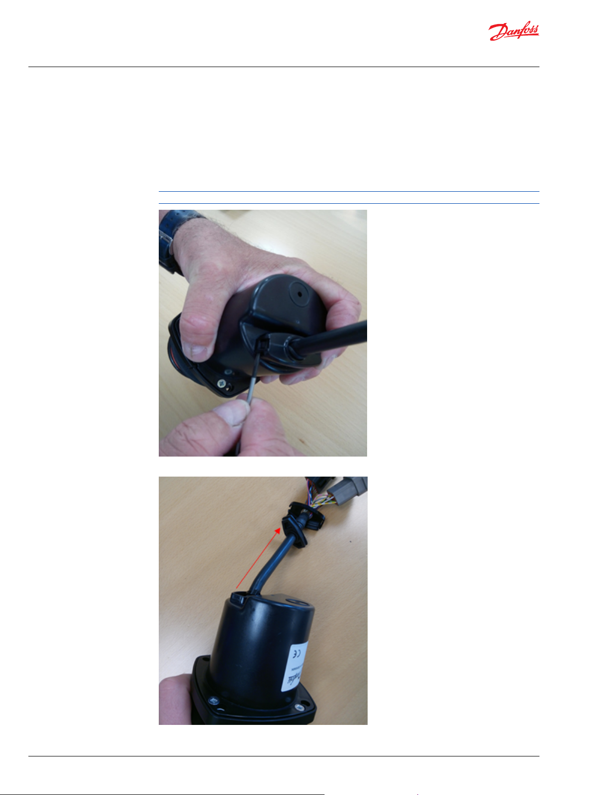
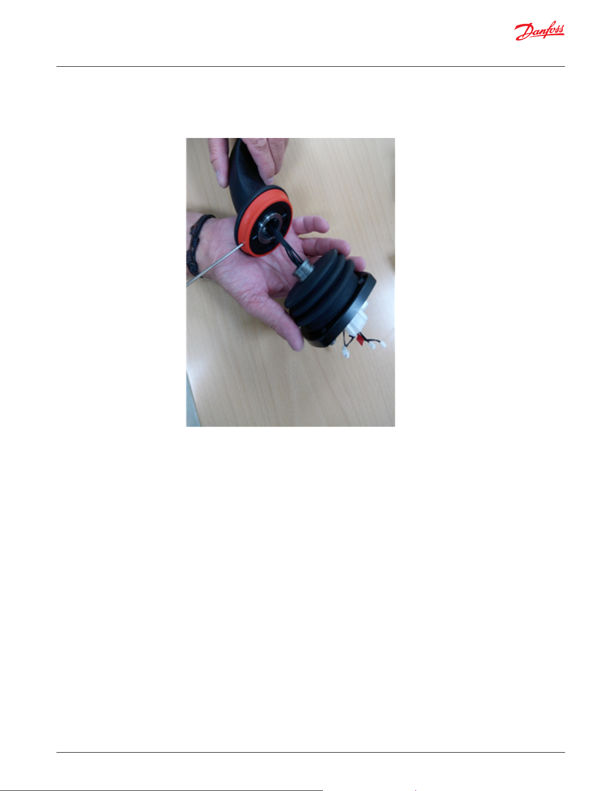
Cup and cable disassembly
1. Remove the retainer by carefully opening the snap with a screwdriver.
The snap can be easily broken. If it is broken, a new cable will need to be purchased.
2. Carefully pull back the grommet while holding the cable.
4 | © Danfoss | July 2019 AX311058842185en-000103
Page 5
Service Manual
JS1-H Serviceability for IP54 Joysticks
HR1, ST7, PR2, ST2, PR7
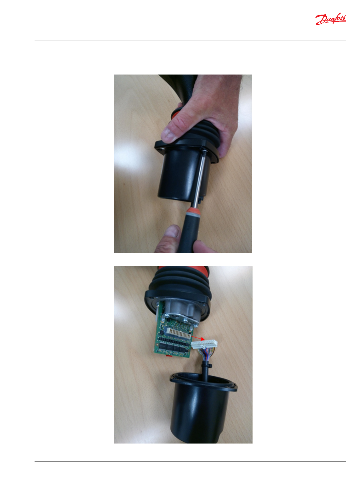
3. Remove the 4 screws to open the cup.
4. Unplug the cable connector.
©
Danfoss | July 2019 AX311058842185en-000103 | 5
Page 6
Service Manual
JS1-H Serviceability for IP54 Joysticks
HR1, ST7, PR2, ST2, PR7
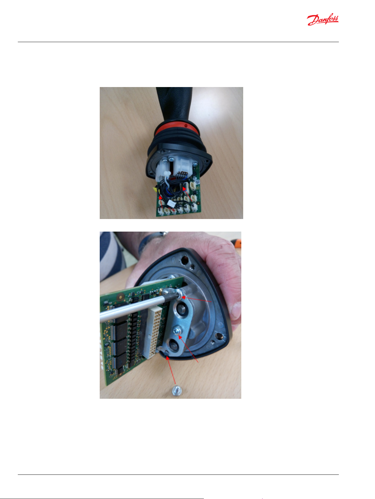
PCBA removal
1. Take a picture to ease the re-installing of the connectors. Unplug all PCBA connectors.
2. Remove the 3 screws from the bottom plate and remove the PCBA.
6 | © Danfoss | July 2019 AX311058842185en-000103
Page 7
Service Manual
JS1-H Serviceability for IP54 Joysticks
HR1, ST7, PR2, ST2, PR7
Grip removal from base
Loosen the 2 set screws and carefully remove the grip (not HR1 and PR7).
©
Danfoss | July 2019 AX311058842185en-000103 | 7
Page 8
Service Manual
JS1-H Serviceability for IP54 Joysticks
HR1, ST7, PR2, ST2, PR7
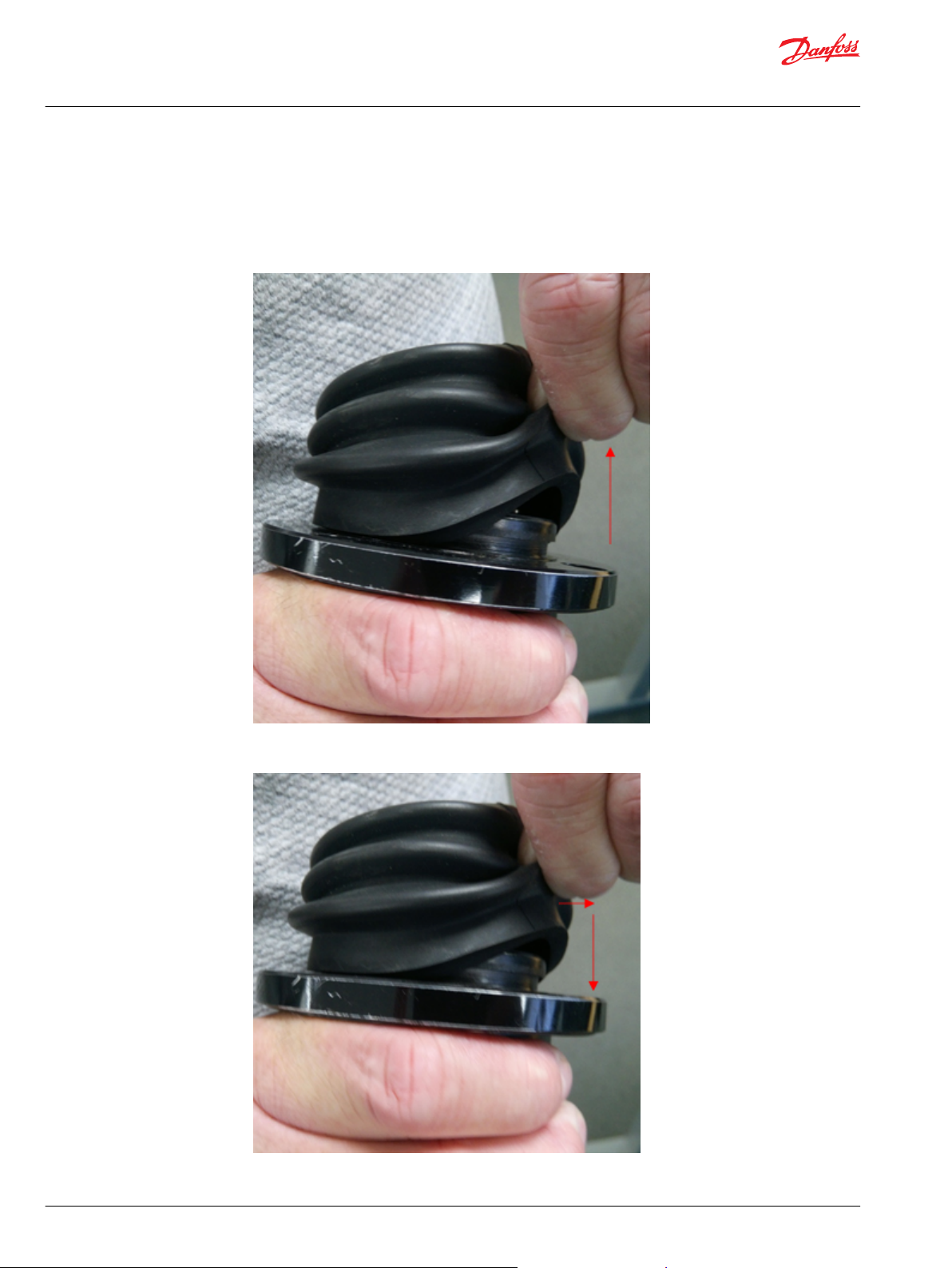
Boot replacement
Grip must be removed, as describe in Grip removal from base on page 7.
The boot can be replaced if desired with the following steps.
1. Hold the boot tightly and pull it off (it is not easy to remove).
2. To re-install the boot, place it all around the base, slightly open it and push down to get in the correct
place.
8 | © Danfoss | July 2019 AX311058842185en-000103
Page 9

Service Manual
JS1-H Serviceability for IP54 Joysticks
HR1, ST7, PR2, ST2, PR7
Cable and cup replacement
The case (cup) will need to be removed to install the cable.
The label from the old case will need to be put back on the new case otherwise all information about the
joystick is lost.
The cable will need to be removed to install the new case.
Refer to Cup and cable disassembly on page 4, at step 4 it is possible to replace either the cable or cup.
1. Carefully take the cable connector out through the grommet hole, replace either the cup or cable and
insert the cable again through the grommet hole.
2. Align the two grooves before tightening the cup back on.
©
Danfoss | July 2019 AX311058842185en-000103 | 9
Page 10

Service Manual
JS1-H Serviceability for IP54 Joysticks
ST7, PR2, ST2
Cable and case will need to be removed, and wires unplugged and pulled through. New wires need to be
routed into the base and installed correctly, then case and cable re-installed. Purchase of a new faceplate
is required. Rollers can only be replaced on analog joysticks.
In order to remove a push button, roller or rocker, the whole faceplate needs to be removed and
replaced.
Remove a push button or a rocker with a flat screwdriver.
Items and faceplate removal
1. Insert a flat screwdriver between the faceplate and the roller and lift it.
2. Push the buttons out using the fingers.
10 | © Danfoss | July 2019 AX311058842185en-000103
Page 11

Service Manual
JS1-H Serviceability for IP54 Joysticks
ST7, PR2, ST2
3. With all items in the faceplate removed, it is now possible to remove the faceplate. Pull it out using
fingers.
4. To re-route all the cables back down to the PCBA, tweezers can be used.
Extreme care is needed since the plug could be pulled out by accident.
©
Danfoss | July 2019 AX311058842185en-000103 | 11
Page 12

Service Manual
JS1-H Serviceability for IP54 Joysticks
ST7, PR2, ST2
Items and faceplate assembly
1. A new faceplate is pushed into the grip and then the same happens with the new items.
2. The cables are then put through the boot and the setscrews tightened (align the back setscrew with
the groove mentioned in Cable and cup replacement on page 9).
Use: Allen Key 2.5 mm, Torque: 2.1 Nm
12 | © Danfoss | July 2019 AX311058842185en-000103
Page 13

Service Manual
JS1-H Serviceability for IP54 Joysticks
ST7, PR2, ST2
Grip assembly
Process as described for the push button in Items and faceplate assembly on page 12, with the addition of
the removal of the grip.
PCBA, cup and cable assembly
1. The PCBA is tightened again.
Use: T20, Torque: 2.5 Nm
PCBA
©
Danfoss | July 2019 AX311058842185en-000103 | 13
Page 14

Service Manual
JS1-H Serviceability for IP54 Joysticks
ST7, PR2, ST2
2. The PCBA connectors are plugged in accordingly and the wires are organized and fastened.
Wires are organized and fastened
Printed circuit board
Plug in connectors accordingly
Position Tape color
H1 Red
H2 Yellow
H3 Blue
H4 Black
H5 White
H6 None
H7 Green
14 | © Danfoss | July 2019 AX311058842185en-000103
Page 15

Service Manual
JS1-H Serviceability for IP54 Joysticks
ST7, PR2, ST2
Plug in connectors accordingly (continued)
Position Tape color
H8 Blue/Black
H9 Yellow/Black
H10 Yellow/Red
H11 White/Red
H12 White/Green
Prop 3 N/A
Prop 4 Yellow
Prop 5 Red
3. The cable is connected again.
4. Screw the cup back on (check Cable and cup replacement on page 9, for correct placement).
Use: PZ 2, Torque: 1.55 Nm
Make sure cables will not get caught when screwing back on the cup.
©
Danfoss | July 2019 AX311058842185en-000103 | 15
Page 16

Service Manual
JS1-H Serviceability for IP54 Joysticks
ST7, PR2, ST2
5. Put the grommet back in place and push in the snap.
Grip replacement
If the grip needs to be replaced, this should be done after step 2 under Items and faceplate removal on
page 10, when all items have been removed from the faceplate. Then the items are put on the new grip
and assembled following steps under Items and faceplate assembly on page 12 and PCBA, cup and cable
assembly on page 13.
16 | © Danfoss | July 2019 AX311058842185en-000103
Page 17

Service Manual
JS1-H Serviceability for IP54 Joysticks
HR1
Grip removal from base
It is possible to remove the HR1 grip from the base, after step 2 under PCBA removal on page 6.
1. Remove the two plastic covers to access the setscrews.
2. Loosen the two setscrews to remove the grip from the base.
Boot, cup and cable replacement
The grip will need to be removed as described in Grip removal from base on page 17. After removing the
grip, refer to Boot replacement on page 8 to replace the boot if desired.
The case will need to be removed to install the cable.
Use: Allen Key 2.5 mm, Torque: 2.8 Nm
To tighten the grip back on, use the tool and torque noted.
The label from the old case will need to be put back on the new case otherwise all information about the
joystick is lost.
The cable will need to be removed to install the new case.
Refer to Cup and cable disassembly on page 4, step 4, in order to replace either the cup or cable.
©
Danfoss | July 2019 AX311058842185en-000103 | 17
Page 18

Service Manual
JS1-H Serviceability for IP54 Joysticks
HR1
Items and grip disassembly
In order to remove a push button, roller, or rocker, the cable and case will need to be removed, wires
unplugged and pulled through.
New wires need to be routed into the base and installed correctly.
Rollers can only be replaced on analog joysticks.
1. Remove all the screws from the grip.
2. The grip will now be divided into 3 parts.
18 | © Danfoss | July 2019 AX311058842185en-000103
Page 19

Service Manual
JS1-H Serviceability for IP54 Joysticks
HR1
3. Push out the item/ items that are not desired and replace with new ones.
4. Close the grip again and tighten the screws back on.
Use: T10, Torque: 1.3 Nm
Items and grip reassembly
Process as described for the push button in Items and grip disassembly on page 18, with the addition of
the removal of the grip. If the grip needs replacing, remove all the items following Items and grip
disassembly on page 18, step 3 and then replace the grip. Refer to Grip assembly on page 13 to
reassemble the full joystick.
©
Danfoss | July 2019 AX311058842185en-000103 | 19
Page 20

Service Manual
JS1-H Serviceability for IP54 Joysticks
PR7
Cup and cable replacement
The case (cup) will need to be removed to install the cable.
The label from the old case will need to be put back on the new case otherwise all information about the
joystick is lost.
The cable will need to be removed to install the new case.
Refer to Cup and cable disassembly on page 4, step 4, in order to replace either the cup or cable.
Items and grip disassembly
In order to remove a push button, roller, or rocker, the cable and case will need to be removed, wires
unplugged and pulled through.
Rollers can only be replaced on analog joysticks.
Refer to PCBA removal on page 6, it is necessary to open the PR7 grip in order to replace the desired
items.
Items replacement
After step 2, under PCBA removal on page 6 it is necessary to open the PR7 grip in order to replace the
desired items.
1. Remove all the screws to open the grip.
20 | © Danfoss | July 2019 AX311058842185en-000103
Page 21

Service Manual
JS1-H Serviceability for IP54 Joysticks
PR7
2. The grip will be divided in 3 parts. It is possible to remove the desired item to replace by using the
fingers to push it out.
3. Close the grip and tighten the screws again.
Use: T10, Torque: 1.3 Nm
©
Danfoss | July 2019 AX311058842185en-000103 | 21
Page 22

Service Manual
JS1-H Serviceability for IP54 Joysticks
PR7
Grip replacement
4. Follow steps under PCBA, cup and cable assembly on page 13 to reassemble the whole joystick.
Process as described for the push button with the addition of the removal of the grip. In order to change
the grip, remove all the items, refer to Items and grip disassembly on page 20 step 2, then separate the
grip from the base.
1. Loosen the setscrew to remove the grip from the base and replace it.
22 | © Danfoss | July 2019 AX311058842185en-000103
Page 23

Service Manual
JS1-H Serviceability for IP54 Joysticks
PR7
2. Tighten the setscrew again, refer to Grip replacement on page 22, step 3 to reassemble.
Use: T10, Torque: 2.8 Nm
Boot replacement
The grip will need to be removed as described under Grip removal from base on page 7. After removing
the grip, it is possible to follow the steps under Boot replacement on page 8 to replace the boot if desired.
©
Danfoss | July 2019 AX311058842185en-000103 | 23
Page 24

Danfoss
Power Solutions GmbH & Co. OHG
Krokamp 35
D-24539 Neumünster, Germany
Phone: +49 4321 871 0
Danfoss
Power Solutions ApS
Nordborgvej 81
DK-6430 Nordborg, Denmark
Phone: +45 7488 2222
Danfoss
Power Solutions (US) Company
2800 East 13th Street
Ames, IA 50010, USA
Phone: +1 515 239 6000
Danfoss
Power Solutions Trading
(Shanghai) Co., Ltd.
Building #22, No. 1000 Jin Hai Rd
Jin Qiao, Pudong New District
Shanghai, China 201206
Phone: +86 21 3418 5200
Products we offer:
Hydro-Gear
www.hydro-gear.com
Daikin-Sauer-Danfoss
www.daikin-sauer-danfoss.com
DCV directional control
•
valves
Electric converters
•
Electric machines
•
Electric motors
•
Hydrostatic motors
•
Hydrostatic pumps
•
Orbital motors
•
PLUS+1® controllers
•
PLUS+1® displays
•
PLUS+1® joysticks and
•
pedals
PLUS+1® operator
•
interfaces
PLUS+1® sensors
•
PLUS+1® software
•
PLUS+1® software services,
•
support and training
Position controls and
•
sensors
PVG proportional valves
•
Steering components and
•
systems
Telematics
•
Danfoss Power Solutions is a global manufacturer and supplier of high-quality hydraulic and
electric components. We specialize in providing state-of-the-art technology and solutions
that excel in the harsh operating conditions of the mobile off-highway market as well as the
marine sector. Building on our extensive applications expertise, we work closely with you to
ensure exceptional performance for a broad range of applications. We help you and other
customers around the world speed up system development, reduce costs and bring vehicles
and vessels to market faster.
Danfoss Power Solutions – your strongest partner in mobile hydraulics and mobile
electrification.
Go to www.danfoss.com for further product information.
We offer you expert worldwide support for ensuring the best possible solutions for
outstanding performance. And with an extensive network of Global Service Partners, we also
provide you with comprehensive global service for all of our components.
Local address:
Danfoss can accept no responsibility for possible errors in catalogues, brochures and other printed material. Danfoss reserves the right to alter its products without notice. This also applies to products
already on order provided that such alterations can be made without subsequent changes being necessary in specifications already agreed.
All trademarks in this material are property of the respective companies. Danfoss and the Danfoss logotype are trademarks of Danfoss A/S. All rights reserved.
©
Danfoss | July 2019 AX311058842185en-000103
 Loading...