

Page 1
Electrical Installation
Joystick
JS120 Single Axis Fingertip
www.danfoss.com
Page 2
Electrical Installation
JS120 Joystick
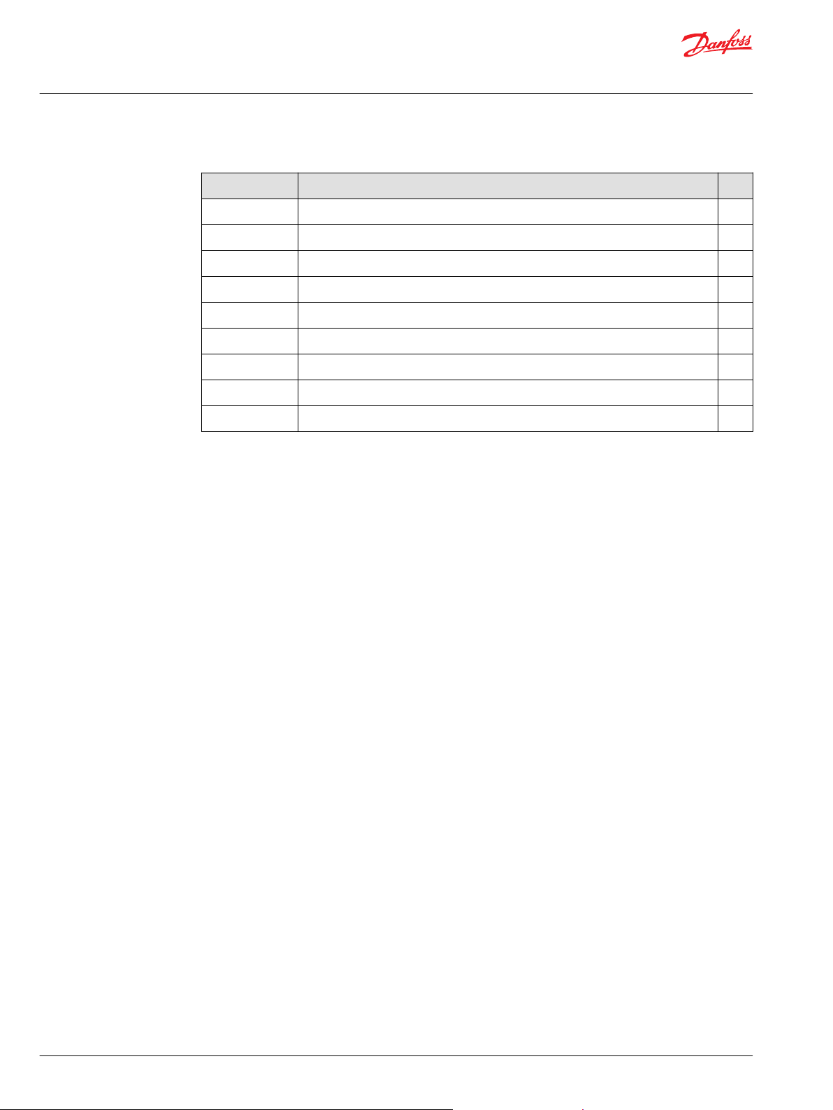
Revision history Table of revisions
Date Changed Rev
June 2019 Reverse the order of the pins instead of G-A going down, it is A-G going down 0601
October 2017 Cable 10101762 is obsolete, replaced with part number 162U1010 0503
May 2017 Updated to Engineering Tomorrow design 0502
December 2016 Corrected pin assignments illustration 0501
September 2015 Minor layout revision DB
July 2014 Conversion to Danfoss layout DA
February 2007 Table corrected CA
October 2006 Various BA
May 2006 First edition AA
2 | © Danfoss | June 2019 11007852 | BC00000247en-000601
Page 3

Electrical Installation
JS120 Joystick
Contents
Danfoss literature references
Product overview
Electrical installation
Technical literature.......................................................................................................................................................................... 4
Theory of operation.........................................................................................................................................................................5
Electrical specifications.................................................................................................................................................................. 5
Pinout....................................................................................................................................................................................................7
Pin compatibility...............................................................................................................................................................................7
Mating connector parts list...........................................................................................................................................................8
©
Danfoss | June 2019 11007852 | BC00000247en-000601 | 3
Page 4
Electrical Installation
JS120 Joystick
Danfoss literature references
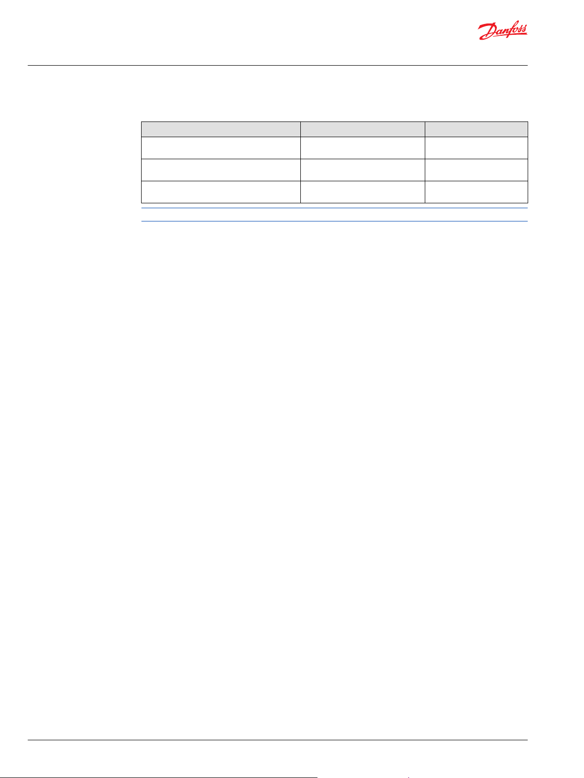
Technical literature
Comprehensive technical literature is online at www.danfoss.com
Title Description Literature number
JS120 Joystick Base Technical Information Complete product electrical and
PLUS+1® Compliant JS120 (spring return to end)
function blocks User’s Guide
PLUS+1® Compliant JS120 (spring return to
center) function blocks User’s Guide
mechanical specifications
Compliant function blocks set-up
information
Compliant function blocks set-up
information
520L0877
11007136
11007137
4 | © Danfoss | June 2019 11007852 | BC00000247en-000601
Page 5
Electrical Installation
JS120 Joystick
Product overview
Theory of operation
Electrical specifications
JS120 joysticks are single axis, finger tip control devices. A single track potentiometer sensor measures
handle position. The nominal output signal range is 10% to 90% of joystick supply voltage. JS120
joysticks are available in two mechanical styles: Spring return to center and spring return to end.
The PLUS+1® Compliant function block 2pt template is used for joysticks that have the spring return-toend option. The 3pt template is used for joysticks that have the spring return-to-center option.
JS120 joysticks have electrically independent switches on the potentiometer track that indicate handle
direction and null position. The PLUS+1® Compliant JS120 compliant function block does not use these
switches. The compliant function block algorithm uses joystick output voltage to determine handle
direction and null position.
The compliant function block requires that the JS120 joystick be supplied with 5 Vdc regulated sensor
power provided by a PLUS+1® control device.
JS120 joysticks may be ordered with one of two output ranges: 25% to 75% of supply voltage or 10% to
90% of supply voltage. The 10% to 90% of supply voltage output range must be selected when using the
PLUS+1® GUIDE compliant function block.
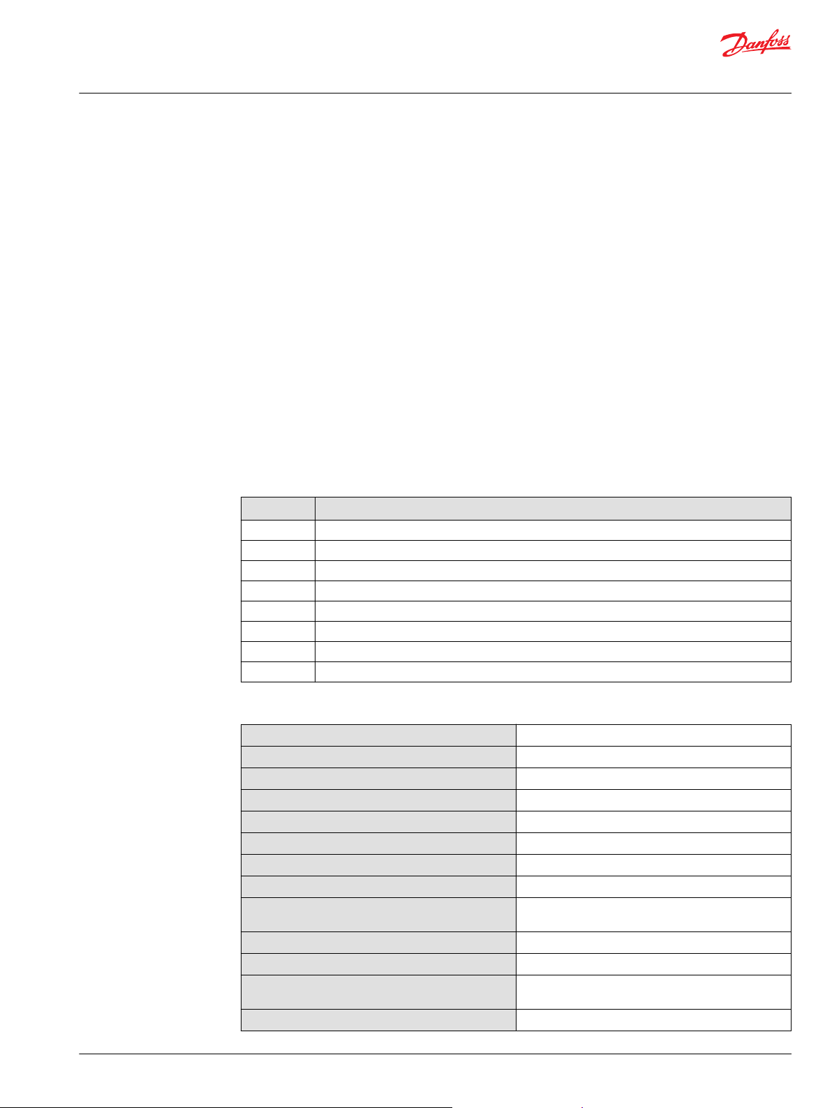
Lever length and output voltage range options
Code Description (Vs = supply voltage)
0002 Short lever, 10 to 90% Vs output range, 5 kΩ, spring return to center
0003 Short lever, 25 to 75% Vs output range, 5 kΩ, spring return to center
0005 Long lever, 10 to 90% Vs output range, 5 kΩ, spring return to center
0006 Long lever, 25 to 75% Vs output range, 5 kΩ, spring return to center
0008 Long lever, 10 to 90% Vs output range, 5 kΩ, spring return to end
0009 Long lever, 25 to 75% Vs output range, 5 kΩ, spring return to end
0010 Short lever, 10 to 90% Vs output range, 5 kΩ, spring return to end
0011 Short lever, 25 to 75% Vs output range, 5 kΩ, spring return to end
Electrical characteristics
Sensor type
Electrical angle of movement center return
Electrical angle of movement end return
Total track resistance
Maximum supply voltage (Vs)
Maximum wiper current
Maximum power dissipation
Wiper circuit impedance
Output voltage
Resolution
Center tap voltage (no load)
Center tap angle (center return)
Insulation resistance
Potentiometric
28° ± 1°
Start 2° ± 1°, end return full angle 56° ± 1°
5 kΩ (± 20%)
35 Vdc
5 mA (non-destructive)
0.25 W at 20°C [68°F]
200 kΩ minimum
10 to 90% Vs
25 to 75% Vs
Infinite
50% Vs ± 2%
± 2.5° either side of center
(± 1° tolerance)
> 50 MΩ at 500 Vdc
©
Danfoss | June 2019 11007852 | BC00000247en-000601 | 5
Page 6

Electrical Installation
JS120 Joystick
Product overview
Electrical characteristics (continued)
Load resistance minimum
Load current maximum
10 kΩ
2 mA resistive
6 | © Danfoss | June 2019 11007852 | BC00000247en-000601
Page 7

kwa1447351557847
kwa1391820928784
ABCDEFG
Electrical Installation
JS120 Joystick
Electrical installation
Pinout
Connector
Pin assignments (connector end view)
Pinout and wiring information
Pin JS120-0002, 0003, 0005, 0006 JS120-0008, 0009, 0010, 0011
A Center tap Not used
B (+) supply (power) (+) supply (power)
C Output voltage Output voltage
D (-) supply (ground) (-) supply (ground)
E Direction switch -Y (N/O) Not used
F Direction switch +Y (N/O) Direction switch (N/O)
G Direction switch common Direction switch common
Pin compatibility
Marker on underside of mating connector indicates pin G
PLUS+1® module pin type
Pin Function
4 Power ground 6 Power supply +
6 Sensor power +
4 Sensor power 5 (only if 5 Vdc power supply is used) AIN/CAN0 shield
5 (only if 5 Vdc power supply is used) AIN/CAN1 shield
1, 2, 3 DIN
1, 2, 3, 5 DIN/AIN
1, 2, 3, 5 DIN/AIN/FreqIN
5 (only if 5 Vdc power supply is used) AIN/Temp/Rheo
©
Danfoss | June 2019 11007852 | BC00000247en-000601 | 7
Page 8
Electrical Installation
JS120 Joystick
Electrical installation
Mating connector parts list
Mating connector – AMPMODU MTE series
Connector AMP ordering number
7 pin latching male 103957-6
Mating connector assembly
Type Danfoss ordering number
7 pin with 610 mm [24.02 in] leads 162U1010
8 | © Danfoss | June 2019 11007852 | BC00000247en-000601
Page 9

Electrical Installation
JS120 Joystick
©
Danfoss | June 2019 11007852 | BC00000247en-000601 | 9
Page 10

Electrical Installation
JS120 Joystick
10 | © Danfoss | June 2019 11007852 | BC00000247en-000601
Page 11

Electrical Installation
JS120 Joystick
©
Danfoss | June 2019 11007852 | BC00000247en-000601 | 11
Page 12

Danfoss
Power Solutions GmbH & Co. OHG
Krokamp 35
D-24539 Neumünster, Germany
Phone: +49 4321 871 0
Danfoss
Power Solutions ApS
Nordborgvej 81
DK-6430 Nordborg, Denmark
Phone: +45 7488 2222
Danfoss
Power Solutions (US) Company
2800 East 13th Street
Ames, IA 50010, USA
Phone: +1 515 239 6000
Danfoss
Power Solutions Trading
(Shanghai) Co., Ltd.
Building #22, No. 1000 Jin Hai Rd
Jin Qiao, Pudong New District
Shanghai, China 201206
Phone: +86 21 3418 5200
Products we offer:
Hydro-Gear
www.hydro-gear.com
Daikin-Sauer-Danfoss
www.daikin-sauer-danfoss.com
DCV directional control
•
valves
Electric converters
•
Electric machines
•
Electric motors
•
Hydrostatic motors
•
Hydrostatic pumps
•
Orbital motors
•
PLUS+1® controllers
•
PLUS+1® displays
•
PLUS+1® joysticks and
•
pedals
PLUS+1® operator
•
interfaces
PLUS+1® sensors
•
PLUS+1® software
•
PLUS+1® software services,
•
support and training
Position controls and
•
sensors
PVG proportional valves
•
Steering components and
•
systems
Telematics
•
Danfoss Power Solutions is a global manufacturer and supplier of high-quality hydraulic and
electric components. We specialize in providing state-of-the-art technology and solutions
that excel in the harsh operating conditions of the mobile off-highway market as well as the
marine sector. Building on our extensive applications expertise, we work closely with you to
ensure exceptional performance for a broad range of applications. We help you and other
customers around the world speed up system development, reduce costs and bring vehicles
and vessels to market faster.
Danfoss Power Solutions – your strongest partner in mobile hydraulics and mobile
electrification.
Go to www.danfoss.com for further product information.
We offer you expert worldwide support for ensuring the best possible solutions for
outstanding performance. And with an extensive network of Global Service Partners, we also
provide you with comprehensive global service for all of our components.
Local address:
Danfoss can accept no responsibility for possible errors in catalogues, brochures and other printed material. Danfoss reserves the right to alter its products without notice. This also applies to products
already on order provided that such alterations can be made without subsequent changes being necessary in specifications already agreed.
All trademarks in this material are property of the respective companies. Danfoss and the Danfoss logotype are trademarks of Danfoss A/S. All rights reserved.
©
Danfoss | June 2019 11007852 | BC00000247en-000601
 Loading...