

PLUS+1™ GUIDE
Software
PLUS+1 Compliant
JS1000 Joystick with
CAN Function Block
User Manual
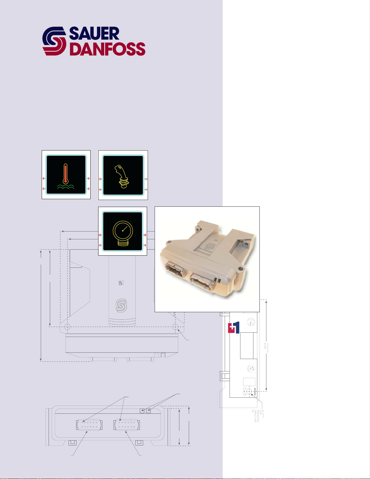
142.0 mm
[5.59]
97.0 mm
[3.82]
TEMP
JOYSTICK
PRESSURE
158.2 mm
6.23
144.5 mm
5.69
2x 25.2 mm
[1.0]
TM
CONNECTOR MATES
WITH DEUTCH
CONNECTOR #D TM-06-125A
2x 7.0
[.28]
MOUNTING
DIRECTION
#2
LED INDICATO R
47.1 mm
[1.85]
LIGHTS
51.6 mm
[2.03]
PIN #1
INDICATED
1
12
6
7
1
12
6
7
CONNECTOR MATES
WITH DEUTCH
CONNECTOR #DTM-06-125A
COMPLIANT
PLUS+1 Compliant JS1000 Joystick with CAN Function Block
User Manual
About this Manual
Organization
and Headings
To help you quickly find information in this manual, the material is divided into sections,
topics, subtopics, and details, with descriptive headings set in red type. Section titles
appear at the top of every page in large red type.
In the PDF version of this document, clicking an item underlined in blue italic type
you to the referenced page in the document.
Special Text Formatting Controls and indicators are set in bold black type.
Table of Contents
A Table of Contents (TOC) appears on the next page. In the PDF version of this document,
the TOC entries are hyperlinked.
Revision History
Revision Date Comment
Rev A May 2006
Rev AB May 2010
Rev AC May 2010
jumps
©2010 Sauer-Danfoss. All rights reserved.
Sauer-Danfoss accepts no responsibility for possible errors in catalogs, brochures and other printed material.
Sauer-Danfoss reserves the right to alter its products without prior notice. This also applies to products already
ordered provided that such alterations can be made without affecting agreed specifications.
All trademarks in this material are properties of their respective owners.
PLUS+1, GUIDE, and Sauer-Danfoss are trademarks of the Sauer-Danfoss Group. The PLUS+1 GUIDE, PLUS+1
Compliant, and Sauer-Danfoss logotypes are trademarks of the Sauer-Danfoss Group.
2
11007135 z Rev AC z May 2010

PLUS+1 Compliant JS1000 Joystick with CAN Function Block
User Manual
Contents
JS1000_CAN Function Block........................................................................................................................ 4
Overview ....................................................................................................................................................4
Inputs........................................................................................................................................................... 4
Outputs....................................................................................................................................................... 5
Status and Fault Logic..........................................................................................................................10
Boolean Output Signals ..............................................................................................................10
Proportional Output Signals......................................................................................................10
Function Block Connections and Signals Example.................................................................... 12
Configuration Of Guide Template Input and Output Buses...................................................12
11007135 z Rev AC z May 2010
3
Overview
PLUS+1 Compliant JS1000 Joystick with CAN Function Block
User Manual
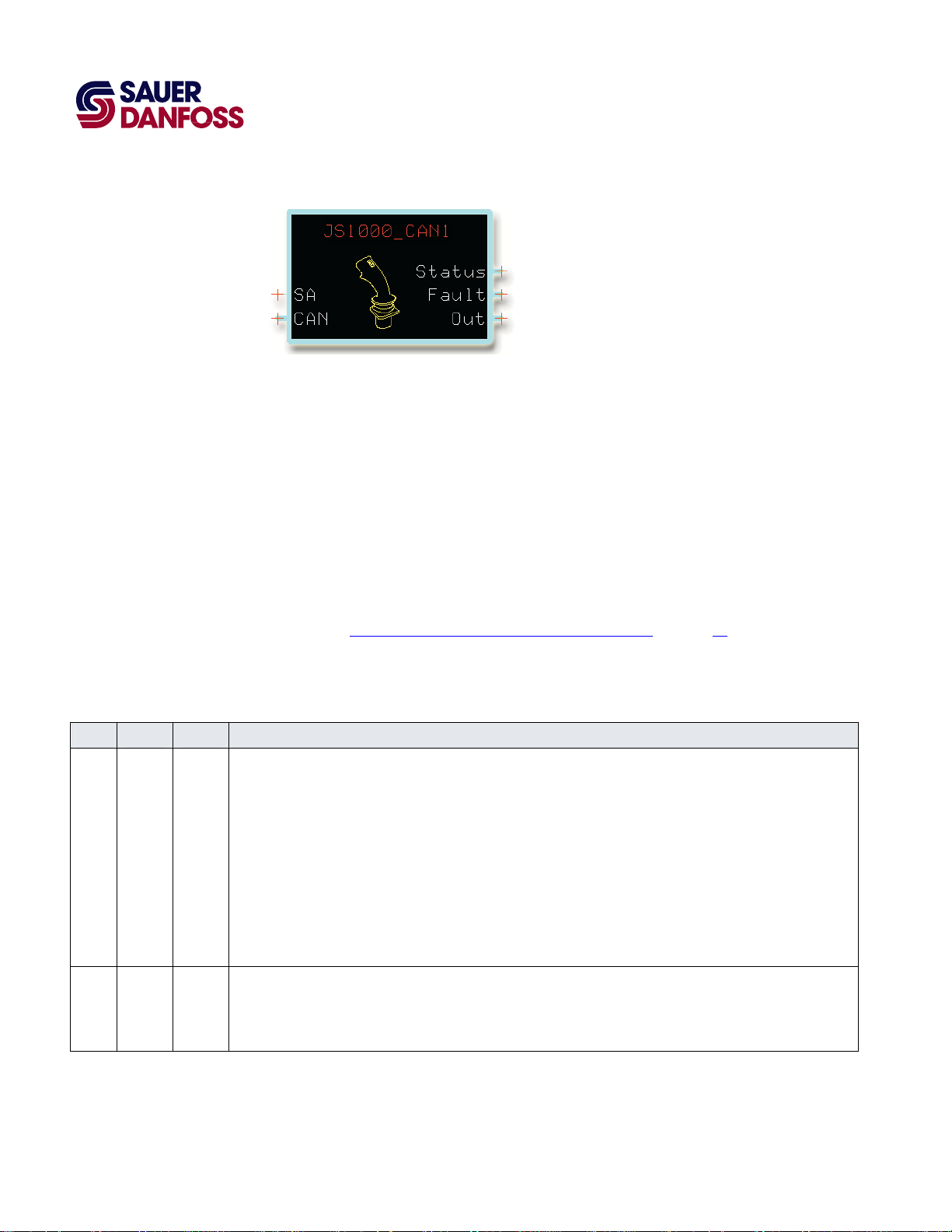
JS1000_CAN Function Block
The JS1000_CAN function block configures the output of a Sauer-Danfoss JS1000 Joystick
with CAN.
This joystick has a CAN (Controller Area Network) 2.0B output that uses the J1939
communication protocol.
The JS1000 Joystick with CAN is a highly configurable joystick that has:
• A joystick base with a single three-point y axis or with three-point x and y axes.
• Up to two grip-mounted proportional three-point rocker switches.
• Up to five grip-mounted push-buttons switches.
Also see the Function Block Connections and Signals Example
on page 12.
Inputs
JS1000_CAN Function Block Inputs
Input Type Range Description
SA —— —— In the GUIDE template, route a Si Digit Autotype component to the SA (Source Address) pin on this function block.
In the Si Digit Autotype component, specify the factory-set source address of the joystick.
All source addresses on the same CAN bus must be different. Do not use the same address twice.
The Type code on the joystick label identifies the source address. Typical addresses are J33 (right), J34 (left),
J35 (center), and J36 (auxiliary).
Enter the source address in hexadecimal format as shown in the following examples:
J33 (right) = 033
J34 (left) = 034
J35 (center) = 035
J36 (auxiliary) = 036
CAN —— —— In the GUIDE template, identify the CAN bus that inputs CAN messages from the joystick. Route this bus to the CAN pin
on this function block.
CAN messages sent from the joystick to the function block contain information about the availability of joystick inputs,
joystick input faults, and joystick commands.
4
11007135 z Rev AC z May 2010

PLUS+1 Compliant JS1000 Joystick with CAN Function Block
User Manual
JS1000_CAN Function Block
Outputs
JS1000_CAN Function Block Outputs
Output Type Range Description
Status —— —— Outputs a bus that contains the following status signals.
Btn1_NA–
Btn12_NA
T_Det_NA BOOL —— Indicates if an input from a detent switch on the joystick’s rotational (theta) axis is
T_NA BOOL —— Indicates if an input from a rotational (theta) axis is available.
Grp_Det_NA BOOL —— Indicates if an input from a grip-mounted, x-axis detent switch is available.
Grp_NA BOOL —— Indicates if an input from a grip-mounted, x-axis, proportional switch is available.
GrpRaw_NA BOOL —— Indicates if an input from a grip-mounted, x-axis, proportional switch is available with
_Det_NA BOOL —— Indicates if an input from a grip-mounted, x-axis, detent switch is available.
_NA BOOL —— Indicates if an input from the joystick’s x axis is available.
YGrp_Det_NA BOOL —— Indicates if an input from a grip-mounted, y-axis detent switch is available.
YGrp_NA BOOL —— Indicates if an input from a grip-mounted, y-axis, proportional switch is available.
Y_Det_NA BOOL —— Indicates if an input from a grip-mounted, y-axis, detent switch is available.
BOOL —— Indicates if an input is available from a grip-mounted push button switch.
T = Not available.
F = Available.
available.
T = Not available.
F = Available.
T = Not available.
F = Available.
T = Not available.
F = Available.
T = Not available.
F = Available.
the raw data format.
T = Not available.
F = Available.
T = Not available.
F = Available.
T = Not available.
F = Available.
T = Not available.
F = Available.
T = Not available.
F = Available.
T = Not available.
F = Available.
11007135 z Rev AC z May 2010
5

PLUS+1 Compliant JS1000 Joystick with CAN Function Block
User Manual
JS1000_CAN Function Block
JS1000_CAN Function Block Outputs
Output Type Range Description
Y_NA BOOL —— Indicates if an input from the joystick’s y axis is available.
T = Not available.
F = Available.
Fault —— —— Outputs a bus that contains the following fault signals.
Btn1_Flt–Btn12_Flt BOOL —— Indicates if the input from a grip-mounted push-button switch has a fault.
T = Fault.
F = No fault.
T_Det_Flt BOOL —— Indicates if the input from a detent switch on the joystick’s rotational (theta) axis has a
fault.
T = Fault.
F = No fault.
T_Flt BOOL —— Indicates if the input from the joystick’s rotational (theta) axis has a fault.
T = Fault.
F = No fault.
TimeOut_BJM BOOL —— Indicates if the function block receives a CAN Rx_BJM (Receive Basic Joystick Message)
within a 100 ms timeout limit.
This message reports joystick x-axis and y-axis positions as well as the state of grip-
mounted button switches.
When this signal is T, the function block sets all Out signals associated with the Rx_BJM
message to either 0 or F. It sets all Fault signals associated with the Rx_BJM message to
T.
When this signal becomes F again, the function block enables all Out signals associated
with the Rx_BJM message. It resets all Fault signals associated with the Rx_BJM message
to F.
T = Message not received within 100 ms limit.
F = Message received within 100 ms limit.
TimeOut_EJM BOOL —— Indicates if the function block receives a CAN Rx_EMJ (Receive Extended Joystick
Message) within a 100 ms timeout limit.
This message reports the position of grip-mounted proportional switches.
When this signal is T, the function block sets all Out signals associated with the Rx_EJM
message to either 0 or F. It sets all Fault signals associated with the Rx_EJM message to
T.
When this signal becomes F again, the function block enables all Out signals associated
with the Rx_EJM message. It resets all Fault signals associated with the Rx_EJM message
to F.
T = Message not received within 100 ms limit.
F = Message received within 100 ms limit.
Grp_Det_Flt BOOL —— Indicates if the input from a grip-mounted, x-axis detent switch has a fault.
T = Fault.
F = No fault.
6
11007135 z Rev AC z May 2010

PLUS+1 Compliant JS1000 Joystick with CAN Function Block
User Manual
JS1000_CAN Function Block
JS1000_CAN Function Block Outputs
Output Type Range Description
Grp_Flt BOOL —— Indicates if the input from a grip-mounted, y-axis proportional switch has a fault.
T = Fault.
F = No fault.
GrpRaw_Flt BOOL —— Indicates if the input from a grip-mounted, y-axis proportional switch with raw mode
has a fault.
T = Fault.
F = No fault.
_Det_Flt BOOL —— Indicates if the input from a detent switch on the joystick’s x axis has a fault.
T = Fault.
F = No fault.
_Flt BOOL —— Indicates if the input from the joystick’s x axis has a fault.
T = Fault.
F = No fault.
YGrp_Det_Flt BOOL —— Indicates if the input from a detent switch on the joystick’s y axis has a fault.
T = Fault.
F = No fault.
YGrp_Flt BOOL —— Indicates if the input from a grip-mounted, y-axis proportional switch has a fault.
T = Fault.
F = No fault.
Y_Det_Flt BOOL —— Indicates if the input from a detent switch on the joystick’s y axis has a fault.
T = Fault.
F = No fault.
Y_Flt BOOL —— Indicates if the input from the joystick’s y axis has a fault.
T = Fault.
F = No fault.
Out —— —— Outputs a bus that contains the following command signals. These signals indicate the
position of each joystick axis and the state of push-button and detent switches.
Btn1–Btn12 BOOL —— Indicates the states of grip-mounted push-button switches.
T = Closed.
F = Open.
R_BJM BOOL —— Indicates when the function block receives a CAN Rx_BJM (Receive Basic Joystick
Message).
This message reports joystick x-axis and y-axis positions as well as the state of grip-
mounted button switches.
T = Message received.
F = Message not received.
11007135 z Rev AC z May 2010
7

PLUS+1 Compliant JS1000 Joystick with CAN Function Block
User Manual
JS1000_CAN Function Block
JS1000_CAN Function Block Outputs
Output Type Range Description
R_EJM BOOL —— Indicates when the function block receives a CAN Rx_EMJ (Receive Extended Joystick
Message).
This message reports the position of grip-mounted proportional switches.
T = Message received.
F = Message not received.
T_Ais_Det BOOL —— Indicates the state of a detent switch on the joystick’s rotational (theta) axis.
T = Closed.
F = Open.
T_Ais_Psn S16 -10000 to +10000 Indicates the position of the joystick’s rotational (theta) axis.
-10000 = -100%
+10000 = +100%
Grp_Det BOOL —— Indicates the state of a detent switch on a grip-mounted, x-axis proportional switch.
T = Closed.
F = Open.
_Grp_Psn S16 -10000 to +10000 Indicates the position of a grip-mounted, x-axis proportional switch.
-10000 = -100%
+10000 = +100%
GrpRaw_Val U16 0 to 1000 Indicates the supply power compensated analog position of a grip-mounted, x-axis
proportional switch.
0 = 0 Counts
1000 = 1000 Counts
_Ais_Det BOOL —— Indicates the state of a detent switch on the joystick’s x-axis.
T = Closed.
F = Open.
_Ais_Psn S16 -10000 to +10000 Indicates the position of the joystick’s x axis.
-10000 = -100%
+10000 = +100%
YGrp_Det BOOL —— Indicates the state of a detent switch on a grip-mounted, y-axis proportional switch.
T = Closed.
F = Open.
YGrp_Psn S16 -10000 to +10000 Indicates the position of a grip-mounted, y-axis proportional switch.
-10000 = -100%
+10000 = +100%
Y_Ais_Det BOOL —— Indicates the state of a detent switch on the joystick’s y-axis.
T = Closed.
F = Open.
8
11007135 z Rev AC z May 2010

PLUS+1 Compliant JS1000 Joystick with CAN Function Block
User Manual
JS1000_CAN Function Block
JS1000_CAN Function Block Outputs
Output Type Range Description
Y_Ais_Psn S16 -10000 to +10000 Indicates the position of the joystick’s y axis.
-10000 = -100%
+10000 = +100%
11007135 z Rev AC z May 2010
9

PLUS+1 Compliant JS1000 Joystick with CAN Function Block
User Manual
JS1000_CAN Function Block
Status and Fault Logic
Boolean Output Signals
The following table shows how the changing states of the Status and Fault signals affect
the value of Boolean output signals.
Status and Fault Logic—Boolean Output Signals
Output Signal Status Signal State Fault Signal State Output Signal Value
Btn1–Btn12, R_BJM, R_EJM, T_Ais_Det, Grp_Det, _Ais_Det, YGrp_Det,
Y_Ais_Det
For example:
• As long as the Status signal and the Fault signal for the Btn1 input are both F, the
Btn1 output signal can be either T or F.
F F T or F
T T F
T F F
F T F
• As soon as either the Status signal or the Fault signal for the Btn1 input becomes T,
the Btn1 output signal goes to and stays F.
• When the Status signal and the Fault signal for the Btn1 input are again both F, the
Btn1 output signal returns to its normal T or F operation.
Proportional Output Signals
The following table shows how the changing states of the Status and Fault signals affect
the value of proportional output signals.
Status and Fault Logic—Proportional Output Signals
Output Signal Status Signal State Fault Signal State Output Signal Value
T_Ais_Psn, _Grp_Psn, _Ais_Psn, YGrp_Psn, Y_Ais_Psn
F F -10000 to +10000
T T 0
T F 0
F T 0
Status and Fault Logic—Raw Proportional Output Signals
Output Signal Status Signal State Fault Signal State Output Signal Value
GrpRaw_Val
F F 0 to 1000
T T 0
T F 0
F T 0
10
11007135 z Rev AC z May 2010

PLUS+1 Compliant JS1000 Joystick with CAN Function Block
User Manual
JS1000_CAN Function Block
For example:
• As long as the Status signal and the Fault signal for the T_Ais_Psn input are both F,
the T_Ais_Psn output signal ranges from -10000 to +10000.
• As soon as either the Status signal or the Fault signal for the T_Ais_Psn input
becomes T, the T_Ais_Psn output signal goes to and stays at 0.
• When the Status signal and the Fault signal for the T_Ais_Psn input are again both F,
the T_Ais_Psn output signal returns to its normal -10000 to +10000 operation.
11007135 z Rev AC z May 2010
11

PLUS+1 Compliant JS1000 Joystick with CAN Function Block
User Manual
JS1000_CAN Function Block
Function Block Connections and Signals Example
Specifies factory-set joystick address
CAN messages from the joystick
Commands
Faults
Configuration Of Guide Template Input and Output Buses
You do not have to change the configuration of either input or output buses to use the
JS1000_CAN function block.
Status
12
11007135 z Rev AC z May 2010

PLUS+1 Compliant JS1000 Joystick with CAN Function Block
User Manual
(This page is intentionally blank.)
11007135 · Rev AC · May 2010

OUR PRODUCTS
Hydrostatic transmissions
Hydraulic power steering
Electric power steering
Electrohydraulic power steering
Closed and open circuit axial piston
pumps and motors
Gear pumps and motors
Bent axis motors
Orbital motors
Transit mixer drives
Planetary compact gears
Proportional valves
Sauer-Danfoss Hydraulic Power Systems
- Market Leaders Worldwide
Sauer-Danfoss is a comprehensive supplier providing complete
systems to the global mobile market.
Sauer-Danfoss serves markets such as agriculture, construction, road
building, material handling, municipal, forestry, turf care, and many
others.
We offer our customers optimum solutions for their needs and
develop new products and systems in close cooperation and
partnership with them.
Sauer-Danfoss specializes in integrating a full range of system
components to provide vehicle designers with the most advanced
total system design.
Sauer-Danfoss provides comprehensive worldwide service for its products
through an extensive network of Global Service Partners
strategically located in all parts of the world.
Directional spool valves
Cartridge valves
Hydraulic integrated circuits
Hydrostatic transaxles
Integrated systems
Fan drive systems
Electrohydraulics
Microcontrollers and software
Electric motors and inverters
Joysticks and control handles
Displays
Sensors
11007135
z
Rev AC z May 2010
Local address:
Sauer-Danfoss Inc.
3500 Annapolis Lane North
Minneapolis, MN 55447, USA
Phone: +1 763 509-2000
Fax: +1 763 559-5769
Sauer-Danfoss (US) Company
2800 East 13th Street
Ames, IA 50010, USA
Phone: +1 515 239-6000
Fax: +1 515 239-6618
Sauer-Danfoss ApS
DK-6430 Nordborg, Denmark
Phone: +45 7488 4444
Fax: +45 7488 4400
Sauer-Danfoss GmbH & Co. OHG
Postfach 2460, D-24531 Neumünster
Krokamp 35, D-24539 Neumünster, Germany
Phone: +49 4321 871-0
Fax: +49 4321 871 122
Sauer-Danfoss-Daikin LTD
Shin-Osaka TERASAKI 3rd Bldg. 6F
1-5-28 Nishimiyahara, Yodogawa-ku
Osaka 532-0004, Japan
Phone: +81 6 6395 6066
Fax: +81 6 6395 8585
www.sauer-danfoss.com
 Loading...