

Page 1
Technical Information
Joysticks
JS1000, JS6000 Grips
www.danfoss.com
Page 2
Technical Information
JS1000, JS6000 Joysticks Grips
Revision history Table of revisions
Date Changed Rev
October 2020 Changed document number from 'BC00000072' and '520L0872' to 'BC152886483977' 0903
February 2018 New boot part number 0801
June 2016 Corrected part numbers for Rocker switch and Banana switch covers; updated to
Engineering Tomorrow design
February 2016 Converted to Danfoss layout 0701
June 2013 Grip Button Color Options table HA
January 2010 A Grip Front Plate Diagram illustration GA
December 2009 Pro grip recommendation, IP rating FA
September 2008 obsolete joystick removed, replaced with ball grip EA
04 Jan, 2008 Content update DA
December 2005 Operating and storage temperature updated C
0702
2 | © Danfoss | October 2020 BC152886483977en-000903
Page 3

Technical Information
JS1000, JS6000 Joysticks Grips
Contents
General Information
Introduction........................................................................................................................................................................................4
JS1000, JS6000 grip selection guide..........................................................................................................................................4
Grip options and joystick base compatibility................................................................................................................... 4
Product configuration model code......................................................................................................................................5
JS1000 grips
JS1000 base model code............................................................................................................................................................... 6
JS1000 grip model code.................................................................................................................................................................7
PRO grip.............................................................................................................................................................................................10
Overview......................................................................................................................................................................................10
Model code nomenclature....................................................................................................................................................10
Specifications.............................................................................................................................................................................10
Connector pin assignments..................................................................................................................................................11
Front plate model code designations...............................................................................................................................12
Dimensions................................................................................................................................................................................. 13
Grip with rocker switch and grip with banana switch......................................................................................................14
Overview......................................................................................................................................................................................14
Model code nomenclature....................................................................................................................................................14
Specifications.............................................................................................................................................................................14
Connector pin assignments..................................................................................................................................................15
Grip with rocker switch dimensions.................................................................................................................................. 15
Grip with banana switch dimensions................................................................................................................................16
Ball grip..............................................................................................................................................................................................17
Overview......................................................................................................................................................................................17
Model code nomenclature....................................................................................................................................................17
Specifications.............................................................................................................................................................................17
Connector pin assignments..................................................................................................................................................17
Dimensions................................................................................................................................................................................. 18
JS6000 grips
JS6000 base model code.............................................................................................................................................................19
JS6000 grips model code............................................................................................................................................................ 20
JS6000 connector pin assignments.........................................................................................................................................22
A grip.................................................................................................................................................................................................. 23
Overview......................................................................................................................................................................................23
Model code nomenclature....................................................................................................................................................23
Front plate model code designations...............................................................................................................................25
Rocker switch profiles............................................................................................................................................................. 26
Rocker switch specifications.................................................................................................................................................26
Rocker switch wiring details................................................................................................................................................. 27
Pushbutton specifications.....................................................................................................................................................28
Pushbutton wiring details.....................................................................................................................................................29
A grip connector pin assignments..................................................................................................................................... 30
Dimensions................................................................................................................................................................................. 33
MG grip.............................................................................................................................................................................................. 34
Overview......................................................................................................................................................................................34
Model code nomenclature....................................................................................................................................................35
Specifications.............................................................................................................................................................................36
MG grip connector pin assignments................................................................................................................................. 36
Switch wiring details............................................................................................................................................................... 37
Dimensions................................................................................................................................................................................. 39
HKN grip............................................................................................................................................................................................ 40
Overview......................................................................................................................................................................................40
Model code................................................................................................................................................................................. 40
Environmental specifications...............................................................................................................................................40
Dimensions................................................................................................................................................................................. 40
Service parts
JS1000 service part availability................................................................................................................................................. 41
©
Danfoss | October 2020 BC152886483977en-000903 | 3
Page 4
Technical Information
JS1000, JS6000 Joysticks Grips
General Information
Introduction
Danfoss joysticks offer mobile machine product engineers a wide array of grip designs. Each of the grip
designs outlined in this document meets the demanding conditions typically found in mobile equipment
environments.
The many available grip features provide OEM engineers with options offering a high degree of
protection from chemicals, high-pressure wash, shock, vibration and EMC exposure. Danfoss grips are
appropriate for both in-cabin and out of cabin applications and feature ergonomic forms that minimize
machine operator fatigue.
This publication provides technical information required to specify the grip portion of JS1000 and JS6000
joysticks. Danfoss JS1000 Joystick Base Technical Information, BC152886484104 and JS6000 Joystick Base
Technical Information, BC152886483634 provide technical information required to specify joystick bases.
JS1000, JS6000 grip selection guide
Grip options and joystick base compatibility
Use the following table to determine which joystick base mates with specific Danfoss joystick grips.
JS1000, JS6000 grip options and joystick base compatibility
Grip designation Compatible with Grip functionality (maximum number) Operator presence
Momentary switches Proportional inputs
JS1000 base JS6000 base Rocker Banana Roller
PRO X X (6) X (2)
Grip with Rocker Switch X X (1)
Grip with Banana
Switch
Ball X
A X X (8) X (2) X (1)
MG X X (2) X (1)
HKN X
X X (1)
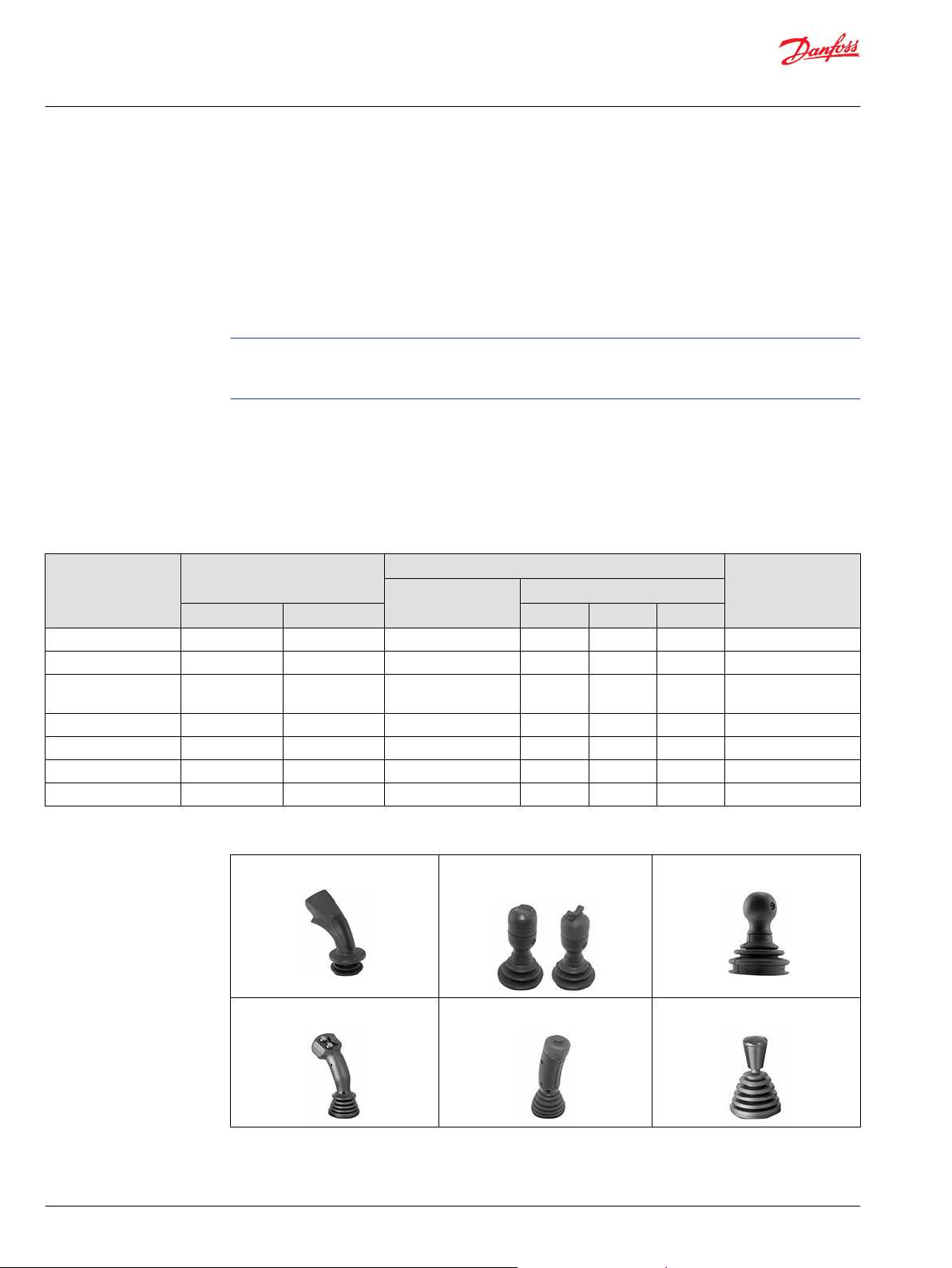
JS1000, JS6000 grips
PRO grip Grip with rocker switch and grip
Ball grip
with banana switch
A grip MG grip HKN grip
4 | © Danfoss | October 2020 BC152886483977en-000903
Page 5

Technical Information
JS1000, JS6000 Joysticks Grips
General Information
Product configuration model code
A product configuration model code (model code) is used to specify particular features when ordering
JS1000 or JS6000 joysticks. The model code begins with the product family name and the remaining
fields are filled in to configure the product with the desired features.
JS1000 and JS6000 model codes contain information relating to both base features and grip features.
©
Danfoss | October 2020 BC152886483977en-000903 | 5
Page 6
Technical Information
JS1000, JS6000 Joysticks Grips
JS1000 grips
JS1000 base model code
JS1000 grip product configuration model code example—base part A, B, C, D and E1
A B C D E F G H J
1 2 3 1
J S 1 0 0 0 X Y A J 3 3 1 T
A—Product family
Code Description
JS1000 JS1000 joystick base with DEUTSCH connector, spring return to center
B—Single or dual axis
Code Description
XY
NY Single axis function, forward and reverse
NG Dual axis function, without guided axis feel (free moving in all directions)
Dual axis function, forward and reverse with left and right, with guided axis
(force is increased in the corners)
C—Center return spring
Code Description
A Standard spring
B Heavy spring
D1—Electrical interface options
Code Description
J CAN with J1939 message protocol
S Analog voltage output
D2—Joystick CAN source address
Code Description
NN None—use with analog output (when D1=S)
33 Source address = 33 (hex)
34 Source address = 34 (hex)
35 Source address = 35 (hex)
36 Source address = 36 (hex)
D3—Joystick output type
Code Description
N None—use with analog output (when D1=S)
1 CAN full scale output = 1000 counts
E1—Grip mounting options
Code Description
B Bottom mount (from below the panel, no boot retainer included, boot is captured between panel and housing) with vent plug
C Bottom mount (from below the panel, no boot retainer included, boot is captured between panel and housing) without vent plug
*
*
6 | © Danfoss | October 2020 BC152886483977en-000903
Page 7
Technical Information
JS1000, JS6000 Joysticks Grips
JS1000 grips
E1—Grip mounting options (continued)
Code Description
T Top mount (from above the panel, includes boot retainer for attaching boot to joystick housing) with vent plug
U Top mount (from above the panel, includes boot retainer for attaching boot to joystick housing) without vent plug
*
Vent plug is a Gore-Tex® moisture barrier. If the plug is not present, Ingress Protection below the base is unrated.
PRO grip option top mount only.
JS1000 grip model code
JS1000 grip product configuration model code example—joystick part E2 and F
A B C D E F G H J
1 2 1 2 3 4
J S 1 0 0 0 X Y A J 3 3 1 T P R O R 3 R R
E2—Grip mounting and handle options
Code Description
PRO PRO grip, CAN output. Complete section F, G, H, J
PR1 PRO grip, with no switch or proportional functions, CAN output.
K01 Ball grip Do not complete F, G, H, J
LSW Grip with analog rocker switch, 1.15 to 3.75 V DC range. Do not complete F, G, H, J
LSB Grip with banana switch, 1.15 to 3.75 V DC range. Do not complete F, G, H, J
*
*
PRO grip available with CAN option only. Grips with switches available with analog option only.
F1—PRO grip function layout
Code Description
R... Right handed grip
L... Left handed grip
F2—PRO grip function layout
Code Number of switches on the front plate
.0.. No switches
.1.. 1 switch
.2... 2 switches
.3.. 3 switches
.4.. 4 switches
.5.. 5 switches
F3—PRO grip function layout
Code Type of proportional function
..R. Roller or wheel, not sealed
..N. None
©
Danfoss | October 2020 BC152886483977en-000903 | 7
Page 8
Technical Information
JS1000, JS6000 Joysticks Grips
JS1000 grips
F4—PRO grip function layout
Code Position of proportional function
...N No proportional function required
...R Vertical proportional function on the Right-hand side
...L Vertical proportional function on the Left-hand side
...B Horizontal proportional function on the Bottom
...D Vertical proportional functions on both the left and the right-hand sides
...S Horizontal proportional functions as dual set on the top and the bottom
...T Horizontal proportional function on top
JS1000 grip product configuration model code example—joystick part E2 and F
A B C D E F G H J
1 2
J S 1 0 0 0 X Y A J 3 3 1 T P R O R 3 R L R Y Y N R N G N
F—Grip function layout examples
R0NN Right handed, 0 switches, No roller, No position R2RL Right handed, 2 switches, Roller, Left positioned
R1NN Right handed, 1 switches, No roller, No position R3RL Right handed, 3 switches, Roller, Left positioned
R2NN Right handed, 2 switches, No roller, No position R0RB Right handed, 0 switches, Roller, Bottom positioned
R3NN Right handed, 3 switches, No roller, No position R1RB Right handed, 1 switches, Roller, Bottom positioned
R4NN Right handed, 4 switches, No roller, No position R2RB Right handed, 2 switches, Roller, Bottom positioned
R5NN Right handed, 5 switches, No roller, No position R3RT Right handed, 3 switches, Roller, Top positioned
R0RR Right handed, 0 switches, Roller, Right positioned R0RD Right handed, 0 switches, 2 Roller, Dual positioned
R1RR Right handed, 1 switches, Roller, Right positioned R1RD Right handed, 1 switches, 2 Roller, Dual positioned
R2RR Right handed, 2 switches, Roller, Right positioned R0RS Right handed, 0 switches, 2 Roller, Stacked positioned
R3RR Right handed, 3 switches, Roller, Right positioned R1RS Right handed, 1 switches, 2 Roller, Stacked positioned
R0RL Right Handed, 0 switches, Roller, Left positioned R2NR Right handed, 2 switches, No roller, Right positioned
R1RL
Right Handed, 1 switches, Roller, Left positioned
R2NL Right handed, 2 switches, No roller, Left positioned
G1—PRO grip side switch orientation
Code Description
R. Right handed PRO Grip
L. Left handed PRO Grip
G2—PRO grip side switch color
Code Description
.R Red side switch
.Y Yellow side switch
.B Black side switch
.G Grey side switch
.N No side switch
8 | © Danfoss | October 2020 BC152886483977en-000903
Page 9
Technical Information
JS1000, JS6000 Joysticks Grips
JS1000 grips
H—PRO grip front plate switch color selection examples
Code
NNNNN No switches (diagram 0NN*)
RYBGR Position 1 switch Red, position 2 switch Yellow, position 3 switch Black, position 4 switch Grey, position 5 switch Red (diagram 5NN*)
YYYYY 5 Yellow switches (diagram 5NN*)
RNNRB Position 1 switch Red, No position 2 switch, No position 3 switch, position 4 switch Red, position 5 switch Black (diagram 3NN*)
YRNNN Position 1 switch Yellow, Position 2 switch Red, No position 3 switch, No position 4 switch, No position 5 switch (diagram 2RL*)
*
See Front plate model code designations on page 12. Number refers to button location on grip front panel. Select one color code for each switch
specified.
J—Operator Presence switch option not available
Code Description
N No: operator presence switch option not selected
Description
©
Danfoss | October 2020 BC152886483977en-000903 | 9
Page 10
Technical Information
JS1000, JS6000 Joysticks Grips
JS1000 grips
PRO grip
PRO grip
Overview
The PRO grip is a patented ergonomic joystick grip that is designed to minimize operator fatigue in
operations requiring repetitive, precision movement over extended periods of time. The grip is available
in right and left hand versions. The profile of the PRO grip ensures that the operators fingers are close to
input functions thus maximizing functional control. The hand rest at the base of the grip and soft feel
elastomeric palm insert contributes to a comfortable feel and provides additional protection for the
joystick boot.
A unique feature of the grip is the intelligent embedded electronics that allows joystick input information
to be multiplexed into a two-wire serial signal communicating with base electronics. The intelligent
electronics facilitate the compact design of the grip by eliminating the need to pass large numbers of
discrete wires through the joystick shaft.
The PRO grip is available with a maximum of six switch inputs or two proportional inputs, or a mix of
switch and proportional inputs.
The PRO grip is not recommended in an open cab environment.
Model code nomenclature
Grip and grip options are specified using the Danfoss joystick model code. For grips designed to mate
with the JS1000 joystick base, use code positions E2, F, G and J to specify grip properties. Reference
JS1000 base model code on page 6.
The PRO grip uses all portions of the model code. Other JS1000 grips use only the E2 portion of the
model code.
Specifications
PRO grip switches and proportional rollers are internally wired to a microcontroller located in grip. Grip
information is included in joystick base CAN messages.
Electrical
Description Specification
Switch action Momentary
Switch type Single pole, NO
Switch mechanical life 1 million cycles
10 | © Danfoss | October 2020 BC152886483977en-000903
Page 11
Technical Information
JS1000, JS6000 Joysticks Grips
JS1000 grips
Environmental
Description Specification
Operating temperature -30°C to 75°C [-22°F to 167°F]
Storage temperature -40°C to 85°C [-40°F to 185°F]
Environmental sealing (without proportional roller) IP 43
Proportional Roller Specifications
Description Specification
Roller action Spring return to center
Roller electrical output ±1000 counts from null
Roller mechanical life 5 million cycles
Environmental sealing IP 40
Proportional rollers are not to be used in no cabin or open cabin joystick applications.
Connector pin assignments
PRO grips mounted on JS1000 joystick bases that have user inputs—switches, proportional inputs or a
mix of both—must use the CAN electrical output option to transmit grip switch and proportional
function information. Refer to the JS1000 Joystick Base Technical Information, BC152886484104 for grip
CAN message details and connector pin assignments.
©
Danfoss | October 2020 BC152886483977en-000903 | 11
Page 12
0
0NN 0RR 0RL 0RB 0RD
0RS
1NN 1RR 1RL
1RB
2NN
2NR
2RR
2RL
2RB
3NN
4NN
5NN
3RR
3RL
3RT
1RD
1
2
3
4
5
2NL
1
1
1
P3
P3
P3
P3
P3
P3
P3
P4
P4
P4
P3 P4
P4
P3P4
P3P4
P4
2
2
1
2
1
2
3
3
2
3
2
3
3
R1RB - RY
P3
3
4
4
4
3
4
3
4
1
4
1
4
1
4
1
4
5
5
5
5 5
5
5
F1
F2
F3
F4
G2
G1
2 3 4 5 6 7
1
8
9
kwa1392484982079
Technical Information
JS1000, JS6000 Joysticks Grips
JS1000 grips
Front plate model code designations
PRO grip front plate diagram
1. Number of switches
2. 0 Proportional function in grip (prop)
3. Right prop
4. Left prop
5. Bottom/top prop
6. Dual prop
7. Stacked prop
8. Front plate configuration example
9. Position 6
Pushbutton colors
R
Y
B
G
N
Red
Yellow
Black
Grey
None
12 | © Danfoss | October 2020 BC152886483977en-000903
Page 13
4 x Ø4.57
± 0.05
[0.180
±0.002]
Ø59.4
± 0.5
[2.34
± 0.02]
74.2
± 0.5
DIA
[2.92 ± 0.02]
9.4
± 0.5
[0.37 ± 0.02]
53.46
± 0.5
[2.1 ± 0.02]
6.35
± 0.5
[0.25 ± 0.02]
166.0
± 1
[6.55
± 0.04
]
18o REF
18o REF
18o REF
18o REF
28.58
± 0.12
[1.125 ± 0.005]
28.58
± 0.12
[1.125 ± 0.005]
34.92
± 0.5
[1.38 ± 0.02]
34.92
± 0.5
[1.38 ± 0.02]
69.85
± 0.5
[2.75 ± 0.02]
69.85
± 0.5
[2.75 ± 0.02]
57.15
± 0.12
[2.25 ± 0.005]
R2.0
± 0.5
[0.08 ± 0.02]
57.15
± 0.12
[2.25 ± 0.005]
kwa1392484997286
2
4
4
3
3
2
5
7
5
6
1
Technical Information
JS1000, JS6000 Joysticks Grips
JS1000 grips
Dimensions
Pro grip dimensions in millimeters [inches].
1. Pin 1
2. Decreasing X
3. Increasing X
4. Decreasing Y
5. Increasing Y
6. Pin 6
7. Orientation feature
©
Danfoss | October 2020 BC152886483977en-000903 | 13
Page 14

Technical Information
JS1000, JS6000 Joysticks Grips
JS1000 grips
Grip with rocker switch and grip with banana switch
Grip with rocker switch and grip with banana switch
Overview
JS1000 grips with switches are intended to provide a simple, flexible and comfortable operator control
that includes a proportional input device at the top of the grip. Two shapes are available for the
proportional input device: V rocker or banana rocker. Both grips use Hall sensing technology to detect
rocker switch position.
The proportional input generates a nominal 0 to 5 Vdc signal that is used as a change of state (switch)
input.
Model code nomenclature
Grip and grip options are specified using the Danfoss joystick model code. For grips designed to mate
with the JS1000 joystick base, use code positions E2, F, G and J to specify grip properties. Reference
JS1000 base model code on page 6
The grip with rocker switch and grip with banana switch are designated using only the E2 portion of the
code.
Specifications
Top switch electrical
Description Specification
Supply voltage 5.0 ± 0.5 Vdc
Maximum survival voltage 18 Vdc Continuous
Maximum current draw 10 mA
Output at maximum displacement 75% ± 8% of supply voltage
Output at null 50% ± 4% of supply voltage
Output at minimum displacement 23% ± 8% of supply voltage
Top switch environmental
Description Specification
Operating temperature -40°C to 80°C [-40°F to 175°F]
Storage temperature -40°C to 85°C [-40°F to 180°F]
EMI/RFI rating 100 V/m
Mechanical life 6 million cycles
14 | © Danfoss | October 2020 BC152886483977en-000903
Page 15

69.85 ± 0.50
[2.75 ± 0.02]
4X Ø 4.57 ± 0.05
[0.180 ± 0.002]
Ø 59.4 ± 0.50
[2.34 ± 0.02]
R2.03 ± 0.50
[0.08 ± 0.02]
69.85 ± 0.50
[2.75 ± 0.02]
110.63 ± 0.50
[4.35 ± 0.02]
3.80 [0.15]
59.60 ± 0.50
[2.35 ± 0.02]
6.35 ± 0.50
[.25 ±.02]
18˚ REF 18˚ REF
18˚ REF 18˚ REF
1
3
3
4
4
3
4
6
5
2
kwa1392485030073
Technical Information
JS1000, JS6000 Joysticks Grips
JS1000 grips
Connector pin assignments
Both grip-with-switch options may use either the JS1000 base analog or CAN output option. Refer to the
JS1000 Joystick Base Technical Information, BC152886484104 for grip CAN message details and
connector pin assignments.
Grip with rocker switch dimensions
Grip with rocker switch dimensions in millimeters [inches].
1.
Decreasing X
2. Increasing X
3. Decreasing Y
4. Increasing Y
5. Maximum panel feed-through mounting
6. Orientation feature
©
Danfoss | October 2020 BC152886483977en-000903 | 15
Page 16

69.85 ± 0.50
[2.75 ± 0.02]
4X Ø 4.57 ± 0.05
[.180 ± .002]
Ø 59.4 ± 0.50
[2.34 ± 0.02]
69.85 ± 0.50
[2.75 ± 0.02]
115.43 ± 0.50
[4.54 ± 0.02]
59.60 ± 0.50
[2.35 ± .02]
6.35 ± 0.50
[.25 ± 0.02]
18˚ REF 18˚ REF
18˚ REF 18˚ REF
kwa1392485037606
3.80 [0.15]
7
1
1
3
3
4
4
6 5
5
6
2
2
R2.03 ± 0.50
[0.08 ± 0.02]
8
Technical Information
JS1000, JS6000 Joysticks Grips
JS1000 grips
Grip with banana switch dimensions
Grip with banana switch dimensions in millimeters [inches].
1. Decreasing X
2. Increasing X
3. Decreasing Y
4. Increasing Y
5. Decreasing switch
6. Increasing switch
7. Maximum panel feed-through mounting
8. Orientation feature
16 | © Danfoss | October 2020 BC152886483977en-000903
Page 17

Technical Information
JS1000, JS6000 Joysticks Grips
JS1000 grips
Ball grip
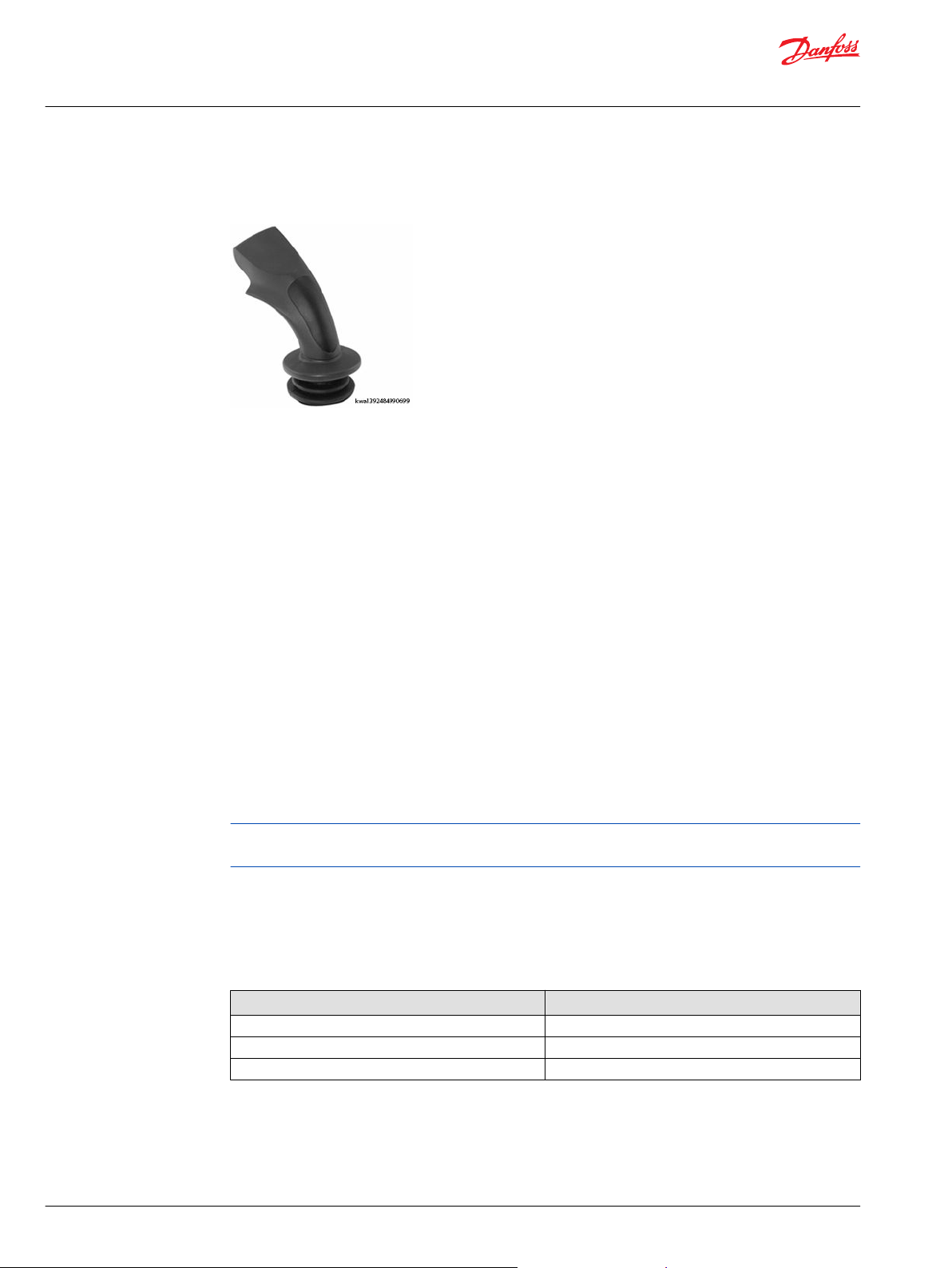
Ball grip
Overview
The JS1000 Ball grip provides a simple and comfortable operator control. Manufactured of high impact
plastic, the grip is perfectly suited for mobile machine applications requiring only X-Y control and no
switch or proportional input options.
Model code nomenclature
Grip and grip options are specified using the Danfoss joystick model code. For grips designed to mate
with the JS1000 joystick base, use code positions E2, F, G and J to specify grip properties. Reference
JS1000 base model code on page 6.
The ball grip is designated using only the E2 portion of the code.
Specifications
Environmental
Description Specification
Operating temperature -40°C to 80°C [-40°F to 175°F]
Storage temperature -40°C to 85°C [-40°F to 180°F]
Environmental protection IP 66, 67
Connector pin assignments
The ball grip has no electrical outputs. It can be mounted on JS1000 bases having either a CAN or analog
output. Refer to the JS1000 Joystick Base Technical Information, BC152886484104 for grip CAN message
details and connector pin assignments.
©
Danfoss | October 2020 BC152886483977en-000903 | 17
Page 18

18o REF
3.8 [0.15]
18o REF
69.85
± 0.5
[2.75
± 0.02
]
18o REF
18o REF
4 x Ø4.57
± 0.05
[0.180
± 0.002]
Ø59.4
± 0.05
[2.34
± 0.002]
59.6
± 0.5
[2.35 ± 0.02]
6.35
± 0.5
[0.25 ± 0.02]
86.61
± 0.5
[3.41 ± 0.02]
R2.03
± 0.5
[0.08 ± 0.02]
kwa1392485052374
1
3
4
2
69.85 ± 0.50
[2.75 ± 0.02]
5
3
4
6
Technical Information
JS1000, JS6000 Joysticks Grips
JS1000 grips
Dimensions
Ball grip dimensions in millimeters [inches].
1. Decreasing X
2. Increasing X
3. Decreasing Y
18 | © Danfoss | October 2020 BC152886483977en-000903
4. Increasing Y
5. Maximum panel feed-through mounting
6. Orientation feature
Page 19

Technical Information
JS1000, JS6000 Joysticks Grips
JS6000 grips
JS6000 base model code
JS6000 product configuration model code example—base part A, B, C, D, E, F and G
A B C D E F G H I J K L M N O P Q R S
J S 6 0 0 0 X Y H M M H S N L N J 3 3 1 A 0 H 0 R V N N N N N N N N
A—Product series
Code Description
JS6000 Series JS6000 joystick
B—Operational axis options
Code Description
XY Bi-directional: X and Y axis
NY Uni-directional: Y axis only (required for friction-holding)
C—Shaft position sensing and output options
Code Description
PRR Potentiometer: single output per axis; Vo = 10 to 90% of Vs; ±1.5° neutral threshold
PQQ
PSS Potentiometer: single output per axis; Vo = 10 to 90% of Vs; ±5° neutral threshold
PTT Potentiometer: single output per axis; Vo = 25 to 75% of Vs; ±5° neutral threshold
PUU Potentiometer: dual output per axis; Vo = 10 to 90% of Vs; ±1.5° neutral threshold
HMM Hall effect: dual sensors per axis; Vs = 5 VDC; Vo = 0.5 to 4.5 VDC
CAN Hall effect: dual sensors per axis; Vs = 9 to 36 VDC; CAN 2.0B communication, 6 pin connector
CPL Hall effect: dual sensors per axis; Vs = 9 to 36 VDC; CAN 2.0B communication, 18 pin connector
Potentiometer: single output per axis; Vo = 25 to 75% of Vs; ±1.5° neutral threshold
D—Centering spring options
Code Description
H Heavy force
M Medium force
L Light force
F Friction-hold (position maintained, center detent)
E—Gate pattern options
Code Description
S Square, full output at 45 degree
F—Mechanical options
Code Description
NL No mechanical option; spring return to center only
FB
©
Danfoss | October 2020 BC152886483977en-000903 | 19
Friction-held in Y axis; no X axis; center detent; 1.25 Nm [0.92 lb•ft] friction-hold force;
2.5 Nm [1.66 lb•ft] breakout force
Page 20

Technical Information
JS1000, JS6000 Joysticks Grips
JS6000 grips
F—Mechanical options (continued)
Code Description
FC
HC
G—Direction (microswitch) options
Code Description
N No switches
Y Microswitches installed (analog potentiometer option only)
JS6000 grips model code
JS6000 grip product configuration model code example—grip properties - I, J, K, L, M, N, O, P, Q, R, and S
J S 6 0 0 0 X Y H M M H S N L N J 3 3 1 A 0 H 0 R V N N N N N N N N
Friction-held in Y axis; no X axis; center detent; 1.25 Nm [0.92 lb•ft] friction-hold force;
3.25 Nm [2.40 lb•ft] breakout force
Friction-held in Y axis; no X axis; center detent; 2.25 Nm [1.66 lb•ft] friction-hold force;
4.0 Nm [2.95 lb•ft] breakout force
A B C D E F G H I J K L M N O P Q R S
1 2 3 4 1 2 3 4
H1—Electrical interface options
Code Description
S Analog (voltage output from joystick sensors or switches)
J CAN, SAE J1939 protocol
H2, 3—CAN Source Address*
Code Description
NN None—use with analog outputs when H1 = S
33 Source address = 0x 33
34 Source address = 0x 34
35 Source address = 0x 35
36 Source address = 0x 36
* Consult the factory if additional source addresses are required.
H4—Joystick output type
Code Description
N None—use with analog outputs when H1 = S
1 CAN full scale output = 1000 counts
I, J, K—Grip proportional rocker output and style
For grips designed to mate with the JS6000 joystick base, use code positions, I through S to specify grip
properties. Refer to Front plate model code designations on page 25 for rocker switch location examples.
20 | © Danfoss | October 2020 BC152886483977en-000903
Page 21
Technical Information
JS1000, JS6000 Joysticks Grips
JS6000 grips
I—Grip switch details
I Code Description
1 Handle type
2 Number of buttons
3 L Left rocker location (vertical orientation)
R Right rocker location (vertical orientation)
B Both left and right (vertical orientation)
H Horizontal rocker location
0 No rocker switch
4 T Top switch
D Operator Presence switch
B Both top and Operator Presence switch
0 No top switch, no Operator Presence switch
J—A grip proportional rocker output
Code Description
R Potentiometer, 10% to 90% Vs
Q Potentiometer, 25% to 75% Vs
N None
K—A grip proportional rocker style
Code Description
S Wave style
V V style
N None
L, M, N, O, P, Q, R, S—Grip options
For A grips use code positions L, M, N, O, P, Q, R, and S to specify grip button colors.
Grip button position to model code conversion
†
Grip front plate button position
1 L
2 M
3 N
4 O
5 P
6 Q
7 R
8 S
See A grip connector pin assignments on page 30.
†
Corresponding master model code
Grip Button Color Options
Code Description
R Red
B Black
©
Danfoss | October 2020 BC152886483977en-000903 | 21
‡
Page 22

Technical Information
JS1000, JS6000 Joysticks Grips
JS6000 grips
Grip Button Color Options (continued)
Code Description
G Green
Y Yellow
L Blue
N No pushbutton switch
‡
The red colored pushbutton switch is considered the default color. There is a five-piece order minimum each time
the other color options are ordered.
JS6000 connector pin assignments
JS6000 grip function connector pin assignments for the JS6000 connector that contains grip outputs are
dependent on the type of joystick shaft position sensor (potentiometer or Hall) and the electrical output
option (analog or CAN) selected for the joystick base. Analog base grip pin assignments are found in A
grip connector pin assignments on page 30 and MG grip connector pin assignments on page 36 of this
manual. Pin assignments for other analog base functions are found in the JS6000 Joystick Base Technical
Information, BC152886483634.
Grip pin assignments for joystick bases that have analog outputs depend on whether a potentiometer or
Hall sensor is used to measure the position of the joystick shaft. If a potentiometer is used, the 12 pin
connector on the joystick base is used for grip outputs. If a Hall sensor is used, the 16 pin connector is
used for grip outputs.
If the CAN electrical output option is selected, a 6 or 18 pin DEUTSCH connector is provided in the base
and input information from the grip is broadcast in a J1939 message format. Refer to the JS6000 Joystick
Base Technical Information, BC152886483634 for details on J1939 CAN grip messages and DEUTSCH
connector pin assignments.
‡
‡
‡
22 | © Danfoss | October 2020 BC152886483977en-000903
Page 23

kwa1392485105672
1
2
3
4
Technical Information
JS1000, JS6000 Joysticks Grips
JS6000 grips
A grip
A grip
Multi-function grip
1. Pushbutton switch
2. Top switch
3. Operator Presence switch
4. Left rocker
Overview
The A grip is a multi-function, ambidextrous ergonomic grip designed for a comfortable user interface
and maximum functional control. The grip features a modular design that allows switch and proportional
rocker location flexibility.
The A grip is available with combinations of up to eight switches and up to two proportional inputs. One
of the optional switches can be used to provide an Operator Presence function on the grip. Available
button colors are red, black, green, yellow, and blue.
Model code nomenclature
Grip and grip options are specified using the Danfoss joystick model code. For grips designed to mate
with the JS6000 joystick base, use code positions I through S to specify grip properties. Reference JS6000
grips model code on page 20.
Model code for a grip front plate options
I Code Number of momentary switches—
grip front plate
A000 0 0 0
A00T 0 0 T
A00D 0 0 D
A00B 0 0 B
A0L0 0 L 0
A0LD 0 L D
A0R0 0 R 0
A0RD 0 R D
A0B0 0 B 0
©
Danfoss | October 2020 BC152886483977en-000903 | 23
Number, location of proportional rocker
switches—grip front plate
Number, location of momentary switches—
back of grip
Page 24

Technical Information
JS1000, JS6000 Joysticks Grips
JS6000 grips
Model code for a grip front plate options (continued)
I Code Number of momentary switches—
grip front plate
A0BD 0 B D
A0H0 0 H 0
A0HD 0 H D
A0RB 0 R B
A0RT 0 R T
A0LB 0 L B
A0LT 0 L T
A100 1 0 0
A10T 1 0 T
A10D 1 0 D
A10B 1 0 B
A1L0 1 L 0
A1R0 1 R 0
A1H0 1 H 0
A1LD 1 L D
A1RD 1 R D
A1HD 1 H D
A1RT 1 R T
A1LT 1 L T
A1RB 1 R B
A1LB 1 L B
A200 2 0 0
A20T 2 0 T
A20D 2 0 D
A20B 2 0 B
A2L0 2 L 0
A2R0 2 R 0
A2H0 2 H 0
A2LD 2 L D
A2RD 2 R D
A2HD 2 H D
A2RB 2 R B
A2RT 2 R T
A2LB 2 L B
A2LT 2 L T
A300 3 0 0
A30T 3 0 T
A30D 3 0 D
A30B 3 0 B
A3R0 3 R 0
A3RD 3 R D
Number, location of proportional rocker
switches—grip front plate
Number, location of momentary switches—
back of grip
24 | © Danfoss | October 2020 BC152886483977en-000903
Page 25

kwa1392485072935
A2H0
A2HD
A300
A30T
A30D
A30B
A400
A40T
A40D
A40B
2
3
X
2
3
1
4
2
3
1
A0B0
A0H0
A0HD
A100
A10T
A10D
A10B
A3L0
A3LT
A3LD
A3LB
X Y
X
X
1
2
6
1
A1R0
A1RT
A1RD
A1RB
A1L0
A1LT
A1LD
A1LB
A1H0
A1HD
A500
A50T
A50D
A50B
2
1
3 Y
X
X
2
3
1
4
5
A200
A20T
A20D
A20B
A2R0
A2RT
A2RD
A2RB
A2L0
A2LT
A2LD
A2LB
A600
A60T
A60D
A60B
1
2
3
2
3
Y
X
2
3
4
1
4
6
5
A000
A00T
A00D
A00B
A0R0
A0RT
A0RD
A0RB
A0L0
A0LT
A0LD
A0LB
A3R0
A3RT
A3RD
A3RB
Y
X
Y
3
5
4
Technical Information
JS1000, JS6000 Joysticks Grips
JS6000 grips
Model code for a grip front plate options (continued)
I Code Number of momentary switches—
grip front plate
A3L0 3 L 0
A3LD 3 L D
A3RT 3 R T
A3LT 3 L T
A400 4 0 0
A40T 4 0 T
A40D 4 0 D
A40B 4 0 B
A500 5 0 0
A50D 5 0 D
A50B 5 0 B
A50T 5 0 T
A600 6 0 0
A60D 6 0 D
A60B 6 0 B
A60T 6 0 T
Number, location of proportional rocker
switches—grip front plate
Number, location of momentary switches—
back of grip
Front plate model code designations
A grip front plate diagram
©
Danfoss | October 2020 BC152886483977en-000903 | 25
Page 26

kwa1392485077632
kwa1456156357759
Technical Information
JS1000, JS6000 Joysticks Grips
JS6000 grips
Rocker switch profiles
Profile of wave rocker switch option
Profile of V rocker switch option
Rocker switch specifications
The optional grip rocker switches use a conductive plastic potentiometer to generate an analog output
that is proportional to switch position. The wipers that run across the potentiometer track are driven by
the thumb operated rocker mechanism. Rocker switch action is spring return to center.
Mechanical
Description Specification
Breakout force 5 N [1.12 lbf]
Operating force 15 N [3.37 lbf]
Maximum applied force 50 N [11.24 lbf]
Mechanical angle of movement ± 12°
Electrical angle of movement ± 9°
Expected life >5 million operations
Environmental
Description Specification
Operating temperature -40°C to 70°C [-40°F to 158°F]
Storage temperature -40°C to 80°C [-40°F to 176°F]
Environmental sealing IP 65
26 | © Danfoss | October 2020 BC152886483977en-000903
Page 27

1
5
6
7
8
11
12
13
14
9
2
10
3
4
kwa1392485086533
Technical Information
JS1000, JS6000 Joysticks Grips
JS6000 grips
Electrical
Description Specification
Maximum load current Potentiometer wiper
Maximum power dissipation 0.25 W at 25° C [77° F]
Output voltage ranges 25 to 75% Vs
Center tap voltage 50% Vs ± 2%
Center tap angle 1.5° either side of center
Directional switch operating angle 2.5° either side of center
Directional switch maximum supply voltage 36 Vdc
Directional switch current rating 5 mA
*
The rocker is only to be used as a potentiometer and not as a variable resistor. Wiper load must be resistance
greater than 100 kΩ.
•
Center tap has an angle of ± 1.5°
•
50% of the Vs is supplied at the center position
•
The track also has a directional switch with a center off switch
•
The direction switch changes state after a movement of 2.5° in each direction
•
The switch current rating is 5 mA
*
Directional switches: 200 mA
10 to 90% Vs
Rocker switch wiring details
Left rocker
1. Black 2. Blue/orange
3. Switch track 4. Green
5. Left blank 6. Center tap (yellow/red)
7. Forwards 8. 0 V
9. Potentiometer track 10. 5 V
11. Backwards 12. White/red (V+)
13. Pink 14. Pink/gray (V-)
©
Danfoss | October 2020 BC152886483977en-000903 | 27
Page 28

1
5
6
7
8
11
12
13
14
9
2
10
3
4
kwa1392485086533
1
5
6
7
8
11
12
13
14
9
2
10
3
4
kwa1392485086533
Technical Information
JS1000, JS6000 Joysticks Grips
JS6000 grips
Right rocker
1. Black 2. Blue
3. Switch track 4. Yellow
5. Left blank 6. Center tap (yellow/red)
7. Backwards 8. 5 V
9. Potentiometer track 10. 0 V
11. Forwards 12. Pink/gray (V+)
13. White 14. White/red (V-)
Horizontal rocker
1. Black 2. Blue
3. Switch track 4. Green
5. Left blank 6. Center tap (yellow/red)
7. Left 8. 0 V
9. Potentiometer track 10. 5 V
11. Right 12. White/red (V+)
13. Pink 14. Pink/gray (V-)
Pushbutton specifications
Electrical
Description Specification
Switch action Momentary
Switch type Single pole, NO
Contact rating 200 mA at 50 Vdc - person present switch
28 | © Danfoss | October 2020 BC152886483977en-000903
Contact resistance 50 MΩ maximum
Mechanical life 1 million cycles
100 mA at 50 Vdc - top and front plate switches
Page 29

1
2
3
4
5
6
7
kwa1392485115566
1
2
kwa1455906231237
1
2
kwa1455906231237
Technical Information
JS1000, JS6000 Joysticks Grips
JS6000 grips
Environmental
Description Specification
Operating temperature -40°F to 70°C [-40°C to 158°F]
Storage temperature -40°F to 80°C [-40°C to 176°F]
Environmental sealing IP 66
Operating force 3 N [0.674 lbf]
Pushbutton wiring details
Pushbutton switches
1. 1 Blue
2. 2 Yellow
3. 3 Yellow/Orange
4. 4 Green
5. 5 Red
6. 6 Violet
7. Black
Top switch
1. Pink with marker sleeve
2. Black
Operator Presence switch
©
Danfoss | October 2020 BC152886483977en-000903 | 29
Page 30

W
Technical Information
JS1000, JS6000 Joysticks Grips
JS6000 grips
1. Red/Green
2. Black/White
A grip connector pin assignments
Warning
Potential uncommanded machine movement. JS6000 base and grip pinout specifications are a function
of joystick base measurement sensor type and electrical output (analog or CAN). For joysticks with analog
output, the pinout assignments for the 12 and 16 pin connectors depend on whether a potentiometer or
Hall sensor is used to measure the position of the joystick shaft. If a potentiometer sensor is used, the 12
pin connector is used for grip outputs. If a Hall sensor is used, the 16 pin connector is used for grip
outputs and pins 13 through 16 are not used. Refer to the Rocker switch specifications on page 26 for
information regarding the switch nomenclature used below. Refer to Front plate model code designations
on page 25 for information regarding the location nomenclature for push button switches.
Pins 13 to 16 are not used on the 16 pin connector
•
Blank = Pin not used
•
A grip button position designations
Code Pin number
1 2 3 4 5 6 7 8 9 10 11 12 13 14 15 16
A000
A00T Top
switch
A00D Operator
presence
A00B Top
switch
A0L0 Switch
out L
A0LD Switch
out L
A0LT Switch
out L
A0LB Switch
out L
A0R0 Switch
A0RD Switch
A0B0 Switch
out L
A0BD Switch
out L
A0H0 Switch
out H
A0HD Switch
out H
A0RT Switch
A100 PB1 Common
Switch
out L
Switch
out L
Switch
out L
Switch
out L
Switch
out L
Switch
out L
out R
out R
Switch
out R
Switch
out R
out R
Switch
out R
Switch
out R
Switch
out R
Switch
out R
Switch
out H
Switch
out H
Switch
out R
VoutL Center tap V+ V- Common
VoutL Center tap V+ Operator
VoutL Center tap V+ Top
VoutL Center tap V+ Operator
Center tap V+ VoutR V- Common
Center tap V+ Operator
VoutL Center tap V+ VoutR V- Common
VoutL Center tap V+ Operator
VoutH Center Tap V+ V- Common
VoutH Centertap V+ Operator
Top
switch
Center tap V+ VoutR V- Common
Operator
presence
presence
presence
presence
presence
presence
switch
Top
switch
VoutR V- Common Operator
VoutR V- Common Operator
Common
Common Operator
Common Operator
V- Common Operator
V- Common
V- Common Operator
V- Common Operator
presence
presence
presence
presence
presence
presence
presence
30 | © Danfoss | October 2020 BC152886483977en-000903
Page 31

Technical Information
JS1000, JS6000 Joysticks Grips
JS6000 grips
A grip button position designations (continued)
Code Pin number
1 2 3 4 5 6 7 8 9 10 11 12 13 14 15 16
A10T PB1 Top
switch
A10D PB1 Operator
presence
A10B PB1 Top
switch
A1L0 Switch
out L
A1R0 PB3 Switch
A1H0 Switch
out H
A1LD Switch
out L
A1RD PB3 Switch
A1HD Switch
out H
A1RT PB3 Switch
A1LT Switch
out L
A1RB PB3 Switch
A1LB Switch
out L
A200 PB3 PB2 Common
A20T PB3 PB2 Top
A20D PB3 PB2 Operator
A20B PB3 PB2 Top
A2L0 Switch
out L
A2R0 PB4 PB3 Switch
A2H0 Switch
out H
A2LD Switch
out L
A2RD PB4 PB3 Switch
A2HD Switch
out H
A2RB PB4 PB3 Switch
Switch
out L
out R
PB2 Switch
Switch
out L
out R
PB2 Switch
out R
Switch
out L
out R
Switch
out L
Switch
out L
PB3 PB2 Switch
Switch
out L
PB3 PB2 Switch
PB2 PB1 VoutL Center tap V+ V- Common
out R
PB2 PB1 VoutL Center tap V+ Operator
out R
out R
PB1 VoutL Center tap V+ V- Common
Switch
out R
out H
PB1 VoutL Center tap V+ Operator
Switch
out R
out H
Switch
out R
PB1 VoutL Center tap V+ Top
Switch
out R
PB1 VoutL Center tap V+ Operator
Switch
out R
out H
Switch
out R
out H
Switch
out R
Center tap V+ VoutR V- Common
VoutH Center top V+ V- Common
Center tap V+ Operator
VoutH Center top V+ Operator
Top
switch
Top
switch
switch
switch
VoutH Center tap V+ V- Common
VoutH Center tap V+ Operator
Top
switch
Center tap V+ VoutR V- Common
Center tap V+ Operator
Center tap V+ VoutR V- Common
Center tap V+ Operator
Center tap V+ Operator
Operator
presence
presence
presence
presence
presence
presence
presence
Operator
presence
presence
presence
presence
presence
VoutR V- Common Operator
switch
VoutR V- Common Operator
Top
switch
VoutR V- Common Operator
VoutR V- Common Operator
Common
Common Operator
Common Operator
V- Common Operator
V- Common Operator
V- Common
V- Common Operator
Common
Common Operator
Common Operator
V- Common Operator
V- Common Operator
presence
presence
presence
presence
presence
presence
presence
presence
presence
presence
presence
presence
presence
©
Danfoss | October 2020 BC152886483977en-000903 | 31
Page 32

Technical Information
JS1000, JS6000 Joysticks Grips
JS6000 grips
A grip button position designations (continued)
Code Pin number
1 2 3 4 5 6 7 8 9 10 11 12 13 14 15 16
A2RT PB4 PB3 Switch
out R
A2LB Switch
out L
A2LT Switch
out L
A300 PB3 PB2 PB1 Common
A30T PB3 PB2 PB1 Top
A30D PB3 PB2 PB1 Operator
A30B PB3 PB2 PB1 Top
A3R0 PB4 PB3 Switch
A3RD PB4 PB3 Switch
A3L0 Switch
out L
A3LD Switch
out L
A3RT PB4 PB3 Switch
A3LT Switch
out L
A400 PB4 PB3 PB2 PB1 Common
A40T PB4 PB3 PB2 PB1 Top
A40D PB4 PB3 PB2 PB1 Operator
A40B PB4 PB3 PB2 PB1 Top
A500 PB4 PB3 PB2 PB1 PB5 Common
A50D PB4 PB3 PB2 PB1 PB5 Operator
A50B PB4 PB3 PB2 PB1 Top
A50T PB4 PB3 PB2 PB1 Top
A600 PB4 PB3 PB2 PB1 PB5 PB6 Common
A60D PB4 PB3 PB2 PB1 PB5 Operator
A60B PB4 PB3 PB2 PB1 Top
A60T PB4 PB3 PB2 PB1 Top
Switch
out L
Switch
out L
Switch
out L
Switch
out L
Switch
out L
PB2 PB1 VoutL Center tap V+ Operator
PB2 PB1 VoutL Center tap V+ Top
out R
out R
PB2 PB1 VoutL Center tap V+ PB6 V- Common
PB2 PB1 VoutL Center tap V+ Operator
out R
PB2 PB1 VoutL Center tap V+ PB6 Top
Switch
out R
Switch
out R
Switch
out R
Switch
out R
Top
switch
switch
switch
PB5 Center tap V+ Operator
Top
switch
switch
switch
switch
switch
switch
switch
Center tap V+ VoutR V- Common
presence
presence
Operator
presence
Center tap V+ PB5 VoutR V- Common
presence
presence
Center tap V+ PB5 VoutR V- Common
presence
Operator
presence
presence
Operator
presence
PB5 Common
presence
PB5 Operator
presence
PB5 PB6 Common
Top
switch
switch
VoutR V- Common Operator
PB6 V- Common Operator
switch
PB5 Common Operator
PB6 Common Operator
PB6 Common Operator
V- Common Operator
V- Common
Common
Common Operator
Common Operator
V- Common
Common
Common Operator
Common Operator
Common Operator
presence
presence
presence
presence
presence
presence
presence
presence
presence
presence
presence
32 | © Danfoss | October 2020 BC152886483977en-000903
Page 33

110 [4.33]
60 [2.36]
131.51 [5.18]
1
2
4
3
kwa1392485122295
Technical Information
JS1000, JS6000 Joysticks Grips
JS6000 grips
Dimensions
A grip dimensions in millimeters [inches].
1. Pushbutton switch
2. Top switch
3. Operator Presence switch
4. Left rocker
©
Danfoss | October 2020 BC152886483977en-000903 | 33
Page 34

1
kwa1392485129828
2
1
kwa1456173068573
Technical Information
JS1000, JS6000 Joysticks Grips
JS6000 grips
MG grip
MG grip
Overview
The MG multi-function grip is designed to provide an ergonomic solution to grip applications requiring
an operator presence function. The profile of the MG grip ensures that the operators fingers are always
close to the buttons to minimize operator fatigue and maximize functional control. An optional hand rest
feature is also available to further minimize operator fatigue and provide additional protection for the
joystick boot.
The grip is available with or without an operator presence lever switch, as well as up to two low current
switches at the top of the grip. If two top switches are present, they are actuated through a rocker
assembly.
0 switch option with Operator Presence lever
1. Operator presence lever
1 switch option with Operator Presence lever
1. Switch 1 position
2. Operator presence lever
34 | © Danfoss | October 2020 BC152886483977en-000903
Page 35

3
2
1
kwa1456173104294
Technical Information
JS1000, JS6000 Joysticks Grips
JS6000 grips
2 switch option with Operator Presence lever
1. Switch 1 position
2. Switch 2 position
3. Operator presence lever
Grip with hand rest option
Model code nomenclature
Grip and grip options are specified using the Danfoss joystick model code. For grips designed to mate
with the JS6000 joystick base, use code positions I, J and K to specify grip properties. Reference JS6000
base model code on page 19.
MG grip model codes do not use model code positions J through S.
Model code for MG grip switch positions
Code Switch position
MG00 No switches No lever No hand rest
MG01 Switch 1 No lever No hand rest
MG02 Switch 1, 2 No lever No hand rest
MG03 Switch 1,2 Included No hand rest
MG04 Switch 1,2 Included Included
MG05 Switch 1 Included Included
MG06 Switch 1,2 No lever Included
MG07 Switch 1 No lever Included
©
Danfoss | October 2020 BC152886483977en-000903 | 35
*
Operator presence lever Hand rest
Page 36

W
Technical Information
JS1000, JS6000 Joysticks Grips
JS6000 grips
Model code for MG grip switch positions (continued)
Code Switch position
MG08 Switch 1 Included No hand rest
MG09 No switches Included Included
MG10 No switches No lever Included
MG11 No switches Included No hand rest
*
Refer to Dimensions on page 39, for definition of switch locations.
Specifications
Electrical
Description Specification
Contact resistance
Contact bounce 1 ms
Insulation resistance >100 MΩ at 50 Vdc
Dielectric strength 500 V (50 Hz, 1 min.)
Switching current Max: 100 mA
Switching voltage Max: 30 Vdc
Electrical life 1 million cycles at maximum voltage
*
Operator presence lever Hand rest
50Ω
Min : 10 µA
Min: 2 Vdc
Environmental
Description Specification
Operating temperature -25°C to 75°C [-13°F to 167°F]
Storage temperature -30°C to 80°C [-22°F to 178°F]
Ingress protection IP 67 (operator presence lever may not operate in icing
conditions)
MG grip connector pin assignments
Warning
Potential uncommanded machine movement. JS6000 base and grip connector pin assignments are a
function of joystick base shaft measurement sensor type and base electrical output (analog or CAN). For
joysticks with analog output, the pin assignments for the 12 and 16 pin base connectors depend on
whether a potentiometer or Hall sensor is used to measure the position of the joystick shaft. If a
potentiometer sensor is used, the 12 pin connector is used for grip outputs. If a Hall sensor is used, the 16
pin connector is used for grip outputs.
12 pin connector MG grip pin assignments
Pin number Description
1 Not used
2 Not used
3 Switch 2
4 Operator presence
5 Operator presence
36 | © Danfoss | October 2020 BC152886483977en-000903
Page 37

1
2 3
kwa1456176163146
Technical Information
JS1000, JS6000 Joysticks Grips
JS6000 grips
12 pin connector MG grip pin assignments (continued)
Pin number Description
6 Switch 1
7 Not used
8 Not used
9 Not used
10 Not used
11 Not used
12 Common for switch 1, 2
16 pin connector MG pin assignments
Pin number Description
1 Not used
2 Not used
3 Switch 2
4 Operator presence
5 Operator presence
6 Switch 1
7 Not used
8 Not used
9 Not used
10 Not used
11 Not used
12 Common for switch 1,2
13 Not used
14 Not used
15 Not used
16 Not used
Switch wiring details
1 switch option
1. Switch 1
2. Blue
3. Black
©
Danfoss | October 2020 BC152886483977en-000903 | 37
Page 38

1
2
3 5
4
kwa1456176219680
1
2 3
kwa1456176163146
Technical Information
JS1000, JS6000 Joysticks Grips
JS6000 grips
2 switch option
1. Switch 1
2. Switch 2
3. Blue
4. Black
5. Green
Operator Presence switch
1. Operator Presence switch
2. Yellow
3. Blue/orange
38 | © Danfoss | October 2020 BC152886483977en-000903
Page 39

188 [ 7.4 ]
28 [ 1.1 ]
114 [ 4.5 ]
14 [ 0.55 ]
54 [ 2.13 ]
ø40 [ø1.57]
ø50 [ø1.97]
kwa1392485132571
1
Technical Information
JS1000, JS6000 Joysticks Grips
JS6000 grips
Dimensions
MG grip dimensions in millimeters [inches].
©
Danfoss | October 2020 BC152886483977en-000903 | 39
Page 40

Technical Information
JS1000, JS6000 Joysticks Grips
JS6000 grips
HKN grip
HKN grip
Overview
The HKN grip is a plain, high impact plastic knob grip that has no electrical interface. It is designed to
provide a comfortable grip for extended machine operation.
Model code
Grip and grip options are specified using the Danfoss joystick model code. For grips designed to mate
with the JS6000 joystick base, use code positions I, through S to specify grip properties. Reference JS6000
base model code on page 19 and JS6000 grips model code on page 20.
The HKN does not use master model code positions J through S.
The master model code for HKN grips is HKN0.
Environmental specifications
Environmental
Description Specification
Operating temperature -40°C to 80°C (-40°F to 176°F)
Storage temperature -40°C to 85°C (-40°F to 185°F)
Environmental sealing IP 66
Dimensions
HKN grip dimensions
Maximum height above flange Maximum diameter
45 mm [1.76 in] 34.6 mm [1.36 in]
40 | © Danfoss | October 2020 BC152886483977en-000903
Page 41

Technical Information
JS1000, JS6000 Joysticks Grips
Service parts
JS1000 service part availability
Service part availability for JS1000 joystick is a function of joystick base and grip specifications. Refer to
the JS1000 Base Technical Information, BC152886484104 for mating connector part information. Refer to
the table below for service part information.
JS1000 joystick grip and base service parts
Grip type Part description
JS1000 ball grip Boot 11112055
JS1000 grip with switch, rocker and
banana
JS1000 PRO grip No replacement parts available
Replacement part
ordering number
Ball grip 10101913
Grip fastening screw 10101782
Rocker switch cover 10103337
Banana switch cover 10101816
©
Danfoss | October 2020 BC152886483977en-000903 | 41
Page 42

Danfoss
Power Solutions GmbH & Co. OHG
Krokamp 35
D-24539 Neumünster, Germany
Phone: +49 4321 871 0
Danfoss
Power Solutions ApS
Nordborgvej 81
DK-6430 Nordborg, Denmark
Phone: +45 7488 2222
Danfoss
Power Solutions (US) Company
2800 East 13th Street
Ames, IA 50010, USA
Phone: +1 515 239 6000
Danfoss
Power Solutions Trading
(Shanghai) Co., Ltd.
Building #22, No. 1000 Jin Hai Rd
Jin Qiao, Pudong New District
Shanghai, China 201206
Phone: +86 21 2080 6201
Products we offer:
Hydro-Gear
www.hydro-gear.com
Daikin-Sauer-Danfoss
www.daikin-sauer-danfoss.com
Cartridge valves
•
DCV directional control
•
valves
Electric converters
•
Electric machines
•
Electric motors
•
Gear motors
•
Gear pumps
•
Hydraulic integrated
•
circuits (HICs)
Hydrostatic motors
•
Hydrostatic pumps
•
Orbital motors
•
PLUS+1® controllers
•
PLUS+1® displays
•
PLUS+1® joysticks and
•
pedals
PLUS+1® operator
•
interfaces
PLUS+1® sensors
•
PLUS+1® software
•
PLUS+1® software services,
•
support and training
Position controls and
•
sensors
PVG proportional valves
•
Steering components and
•
systems
Telematics
•
Danfoss Power Solutions is a global manufacturer and supplier of high-quality hydraulic and
electric components. We specialize in providing state-of-the-art technology and solutions
that excel in the harsh operating conditions of the mobile off-highway market as well as the
marine sector. Building on our extensive applications expertise, we work closely with you to
ensure exceptional performance for a broad range of applications. We help you and other
customers around the world speed up system development, reduce costs and bring vehicles
and vessels to market faster.
Danfoss Power Solutions – your strongest partner in mobile hydraulics and mobile
electrification.
Go to www.danfoss.com for further product information.
We offer you expert worldwide support for ensuring the best possible solutions for
outstanding performance. And with an extensive network of Global Service Partners, we also
provide you with comprehensive global service for all of our components.
Local address:
Danfoss can accept no responsibility for possible errors in catalogues, brochures and other printed material. Danfoss reserves the right to alter its products without notice. This also applies to products
already on order provided that such alterations can be made without subsequent changes being necessary in specifications already agreed.
All trademarks in this material are property of the respective companies. Danfoss and the Danfoss logotype are trademarks of Danfoss A/S. All rights reserved.
©
Danfoss | October 2020 BC152886483977en-000903
 Loading...