

Danfoss JS1 User guide

Technical Information
Joysticks
JS1 Heavy Duty Joysticks
www.danfoss.com
Technical Information
JS1 Heavy Duty Joysticks
Revision history Table of revisions
Date Changed Rev
October 2020 Corrected some information in tables and removed discontinued product line 1305
July 2020 Changed document number from 'BC00000347' to 'BC171886484518' and added cable
model code option W
June 2019 Updated for PWM 1201
November 2018 Moved PR2, PP2 grip cover option H8-Y and put in circle and lowered; Added note to top of
Electronic modules chapter; Updated JS1-H Analog Category 1 and 3 wiring connection
diagrams; Changed FNR IP to IP 66; Under Mechanical, changed table Friction hold/Spring
return, base only, row 1 code to E and row 2 code to J; JS1-H Base model code Table C,
added row PEP; Table D, Changed row 1 code to E and row 2 code to J that applies only
when using XF base; added sub-topic JS1 Heavy Duty Joystick critical mounting under topic
Joystick safety critical functions
August 2018 Updated for spring/friction base 1001
June 2018 Changed vertical maximum load; Added table under Joystick Functions for Operator
Presence Switch (PR7, PPR grip only); Added A and E options for Operator Presence Switch,
in last two rows of table H8-Defining grip side, under chapter Product configuration model
code.
March 2018 Removed J options from PR7, PP7 grip faceplate options; Added Grip only sales and service
options topic; removed the wire color column from all connectors pin tables; corrected H4
through H12 tables under Grip model code; added to types of grips offered for applications
that require high ingress protection; and listed grips with Operator Presence Switch in
Product configuration model code table H7 and H8
January 2018 Added Analog Cat 1, 3 information 0701
1304
1101
0901
0801
November 2017 Added CANalog and CAN+ information 0601
January 2017 Pushbutton color codes updated 0503
January 2017 Removed information that does not apply, corrected PR2 grip options information 0502
December 2016 Added PVE information 0501
October 2016 Updated PR2 faceplate designation; and Environmental IP rating 0403
September 2016 Updated Operating temperature for CAN to 85° C in Environmental table 0402
September 2016 Updates regarding IP switches; Common model code for J3-cable 0401
September 2016 Various updates; updated to Engineering Tomorrow design 0302
February 2016 Removed Connection diagrams chapter 0201
February 2016 First edition 0101
2 | © Danfoss | October 2020 BC171886484518en-001305

Technical Information
JS1 Heavy Duty Joysticks
Contents
Overview
HR1, HP1 grip
ST2, SP2 grip
PR2, PP2 grip
ST7, SP7 grip
PR7, PP7 grip
Compatible grips
Base
Electronic modules
Connection diagrams
JS1-H description..............................................................................................................................................................................6
Features................................................................................................................................................................................................6
Options.................................................................................................................................................................................................7
Description..........................................................................................................................................................................................8
Dimensions.........................................................................................................................................................................................9
Ten total grip functions..................................................................................................................................................................9
Function overview.........................................................................................................................................................................10
Faceplate options.......................................................................................................................................................................... 10
Cover options.................................................................................................................................................................................. 11
Base options.....................................................................................................................................................................................12
Dimensions.......................................................................................................................................................................................14
Five total grip functions...............................................................................................................................................................14
ST2—Faceplate options.............................................................................................................................................................. 15
Cover options.................................................................................................................................................................................. 15
Dimensions.......................................................................................................................................................................................17
Twelve total grip functions.........................................................................................................................................................17
Faceplate options.......................................................................................................................................................................... 18
Cover options.................................................................................................................................................................................. 19
Dimensions.......................................................................................................................................................................................21
ST7—Faceplate options.............................................................................................................................................................. 22
Cover options.................................................................................................................................................................................. 23
Dimensions.......................................................................................................................................................................................25
Faceplate options.......................................................................................................................................................................... 26
Cover options.................................................................................................................................................................................. 27
Dimensions.......................................................................................................................................................................................28
Grip only sales and service options.........................................................................................................................................28
Dimensions.......................................................................................................................................................................................30
CAN..................................................................................................................................................................................................... 31
CAN+...................................................................................................................................................................................................31
CANalog.............................................................................................................................................................................................31
Additional X and Y analog outputs....................................................................................................................................31
Proportional roller output..................................................................................................................................................... 31
PVE.......................................................................................................................................................................................................31
PVE—Standard................................................................................................................................................................................32
PVE—Extended...............................................................................................................................................................................33
Non-Redundant Analog interface (CAT1)............................................................................................................................. 33
Full-Redundant Analog interface (CAT3)...............................................................................................................................33
PWM (Programmable)..................................................................................................................................................................34
CAN+...................................................................................................................................................................................................35
CANalog.............................................................................................................................................................................................36
PVE DSUB.......................................................................................................................................................................................... 37
Analog Cat 1.....................................................................................................................................................................................38
Analog Cat 3.....................................................................................................................................................................................39
PVE Deutsch.....................................................................................................................................................................................40
©
Danfoss | October 2020 BC171886484518en-001305 | 3

Technical Information
JS1 Heavy Duty Joysticks
Contents
PWM....................................................................................................................................................................................................41
Specifications
Mechanical....................................................................................................................................................................................... 42
Electrical—CAN, CAN+, and CANalog.................................................................................................................................... 43
Electrical—PVE (Standard and Extended).............................................................................................................................43
Electrical—PVE (Extended only)...............................................................................................................................................43
Electrical—Analog Cat 1, Cat 3..................................................................................................................................................44
Electrical—PWM.............................................................................................................................................................................44
Environmental.................................................................................................................................................................................44
Joystick functions
Grip options..................................................................................................................................................................................... 45
Push button......................................................................................................................................................................................46
Roller...................................................................................................................................................................................................47
FNR...................................................................................................................................................................................................... 48
Toggle switch.................................................................................................................................................................................. 49
Operator Presence switch...........................................................................................................................................................49
Connector options and cabling
One 6 pin connector..................................................................................................................................................................... 51
Two 6 pin connectors...................................................................................................................................................................52
Two 12 pin connectors.................................................................................................................................................................53
Two 12 pin and one 6 pin connectors....................................................................................................................................54
One 18 pin connector...................................................................................................................................................................55
One 25 pin SUB-D and one 6 pin connectors...................................................................................................................... 57
Mating connectors bag assemblies.........................................................................................................................................58
Cable assemblies............................................................................................................................................................................59
Product configuration model code
JS1-H base and grip model code fields..................................................................................................................................61
JS1-H Base model code.......................................................................................................................................................... 62
Grip model code....................................................................................................................................................................... 65
Other model code.................................................................................................................................................................... 73
Product installation
Joystick safety critical functions............................................................................................................................................... 74
JS1 Heavy Duty Joystick critical mounting......................................................................................................................74
Machine wiring guidelines......................................................................................................................................................... 74
Appendix: CAN J1939 protocol
Joysticks CAN J1939 protocol option..................................................................................................................................... 77
SAE J1939 basic joystick message............................................................................................................................................78
Data field......................................................................................................................................................................................78
JS1-H Basic joystick message data field descriptions..................................................................................................79
Joystick X-axis neutral position status.........................................................................................................................80
Joystick X-axis handle left negative position status............................................................................................... 80
Joystick X-axis handle right positive position status..............................................................................................80
Joystick X-axis position status........................................................................................................................................ 80
Joystick Y-axis neutral position status.........................................................................................................................81
Joystick Y-axis handle back negative position status............................................................................................ 81
Joystick Y-axis handle forward positive position status........................................................................................81
Joystick Y-axis position status.........................................................................................................................................81
Joystick button 1-8 pressed status................................................................................................................................82
SAE J1939 extended joystick message...................................................................................................................................83
Extended joystick message parameters and data field descriptions.....................................................................83
SAE J1939 error (DM1) messages.............................................................................................................................................85
Appendix: CAN+ and CANopen protocol
CANopen Object Dictionary for JS1-H joysticks..................................................................................................................87
Parameter/variable index - JS1-H CAN, JS1-H CANalog...................................................................................................88
Parameter/variable index - JS1-H CAN+..............................................................................................................................100
4 | © Danfoss | October 2020 BC171886484518en-001305

Technical Information
JS1 Heavy Duty Joysticks
Contents
Error handling...............................................................................................................................................................................112
©
Danfoss | October 2020 BC171886484518en-001305 | 5
Technical Information
JS1 Heavy Duty Joysticks
Overview
JS1-H description
A wide variety of new grip designs
The Danfoss JS1 platform offers a wide variety of new grip designs and were developed after extensive
research detailing operator needs. The JS1 heavy duty joysticks (JS1-H) and compatible grips meet the
demanding conditions typically found in mobile equipment environments. The available grips features
provide a high degree of protection from chemicals, shock, vibration and EMC exposure. Danfoss
joysticks are appropriate for both in-cabin and out of cabin applications and feature ergonomic forms
that minimize machine operator fatigue. The JS1-H ergonomic left-hand, right-hand and ambidextrous
grip design options enable efficient operation and comfortable human-machine interface with easy to
use fingertip controls for maximum productivity. The grips feature a modular design that allows switch
and proportional rollers locations flexibility.
Features
•
Hall effect with two sensors per axis or long life potentiometer position sensing
•
Simultaneous operation of two proportional rollers
•
Operator Presence switch
6 | © Danfoss | October 2020 BC171886484518en-001305

Technical Information
JS1 Heavy Duty Joysticks
Overview
Options
Axis
•
Dual Axis Spring Return
•
Single Axis Spring Return
•
Single Axis with Friction
•
Dual Axis with one axis Spring, one axis Friction
Output options
•
CAN J1939
•
CANopen
•
PVE
•
CANalog
•
CAN+
•
Analog Category 1
•
Analog Category 3
•
PWM (programmable)
Ergonomic grip
•
Right hand
•
Left hand
•
Ambidextrous (used with either the left or right hand)
On axis shaft, deflection
•
±18°
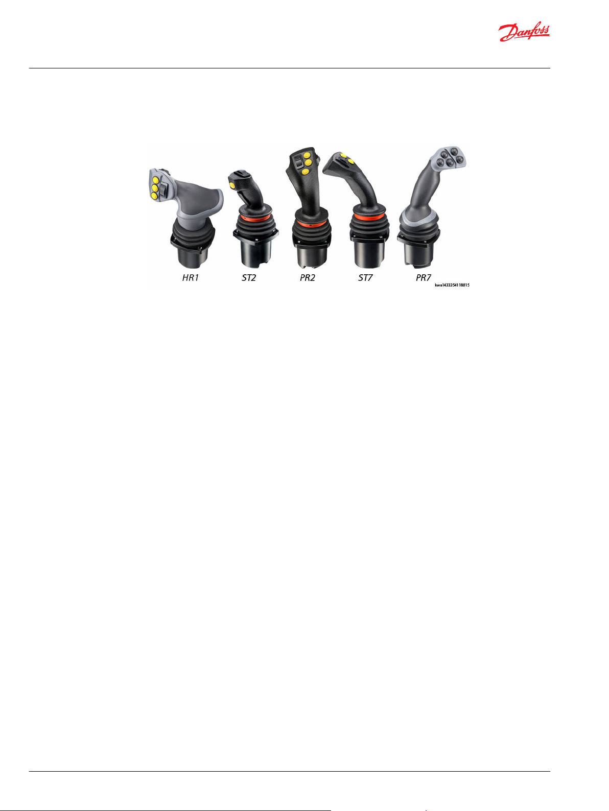
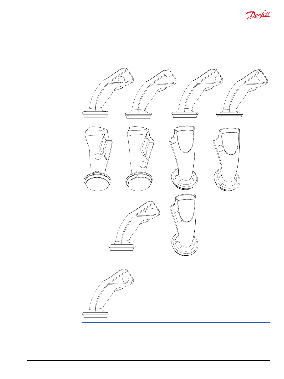
JS1-H grips
•
HR1
•
ST2
•
ST7
•
PR2
•
PR7
©
Danfoss | October 2020 BC171886484518en-001305 | 7
Technical Information
JS1 Heavy Duty Joysticks
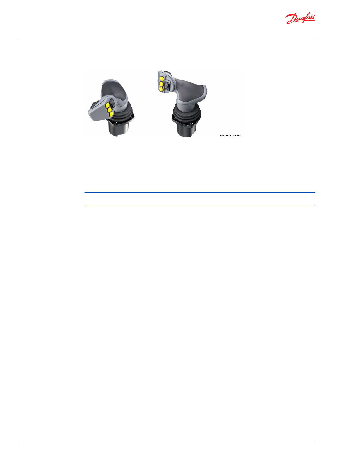
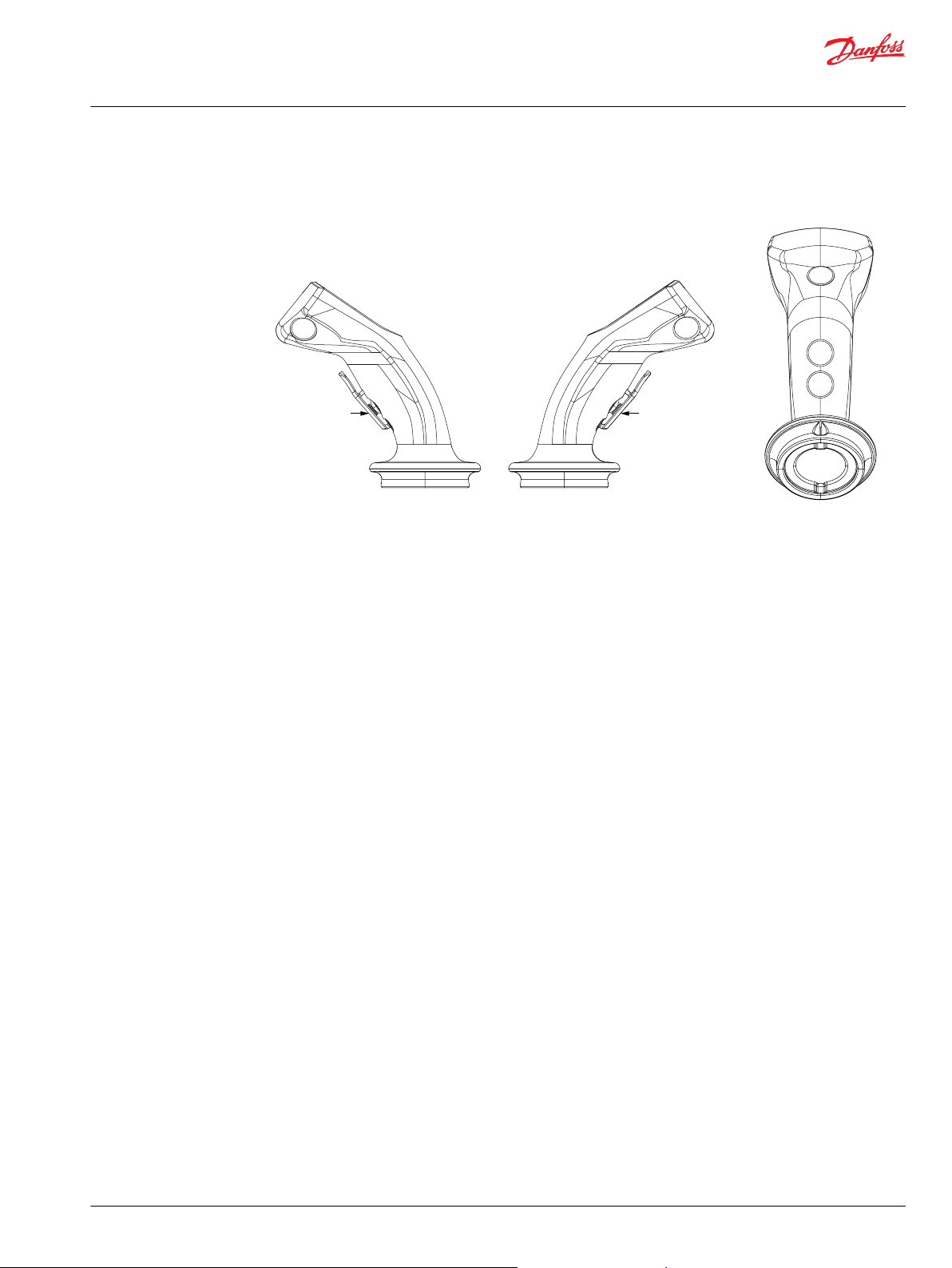
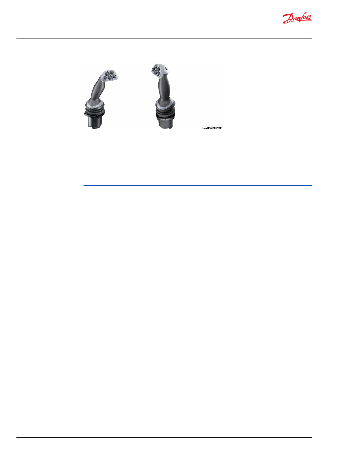
HR1, HP1 grip
Description
Horizontal, multifunction, ergonomic HR1, HP1 grip
The horizontal, multifunction, ergonomic HR1, HP1 grip is designed with easy to use fingertip controls for
a comfortable user interface and maximum functional control.
The grip features a modular design that allows flexibility in the location of switches and proportional
functions.
For applications that require high ingress protection (IP66) select the HP1 grip. For more information, see
ordering code F2, under Grip model code.
8 | © Danfoss | October 2020 BC171886484518en-001305
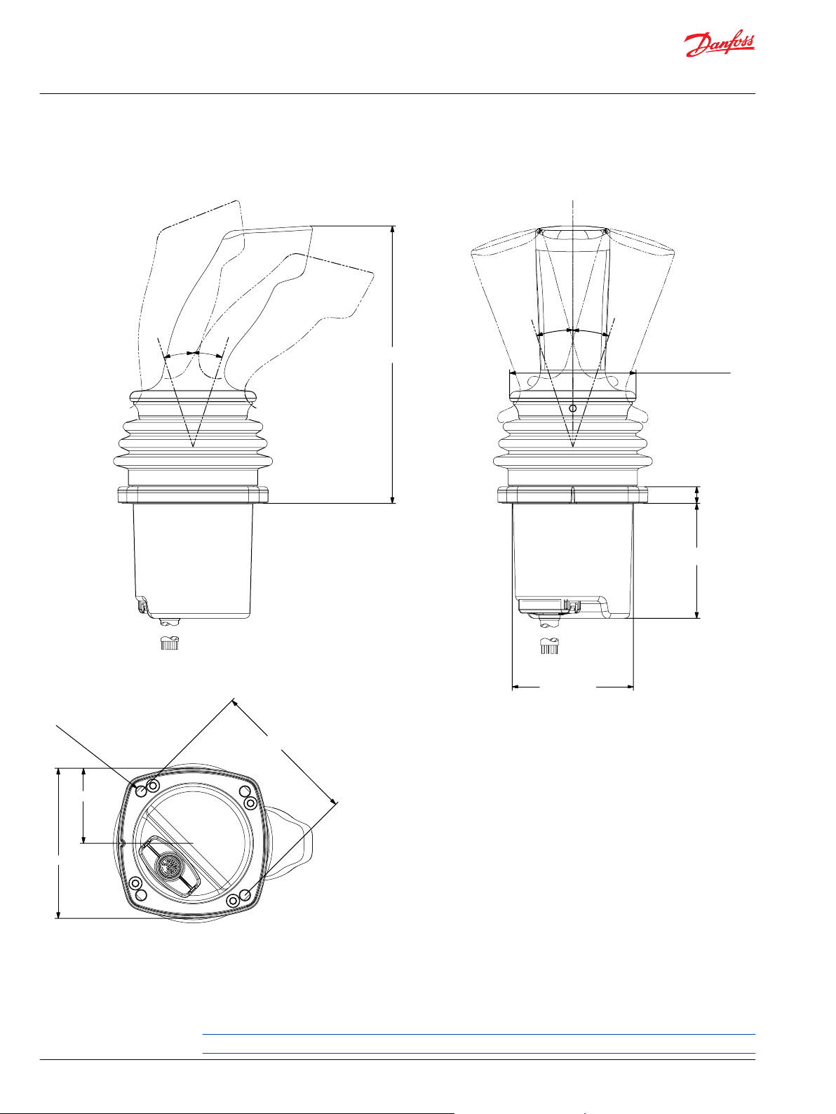
10.00 [0.39]
68.80 [2.71]
Ø 72.60 [2.86]
150.00 [5.90]
88.00 ± 0.05 [3.46 ± 0.002]
Ø 6.00 [0.24]
45.00 [1.77]
90.00 [3.54]
145.00 [5.73]
18° 18°
18° 18°
kwa1433358071249
Technical Information
JS1 Heavy Duty Joysticks
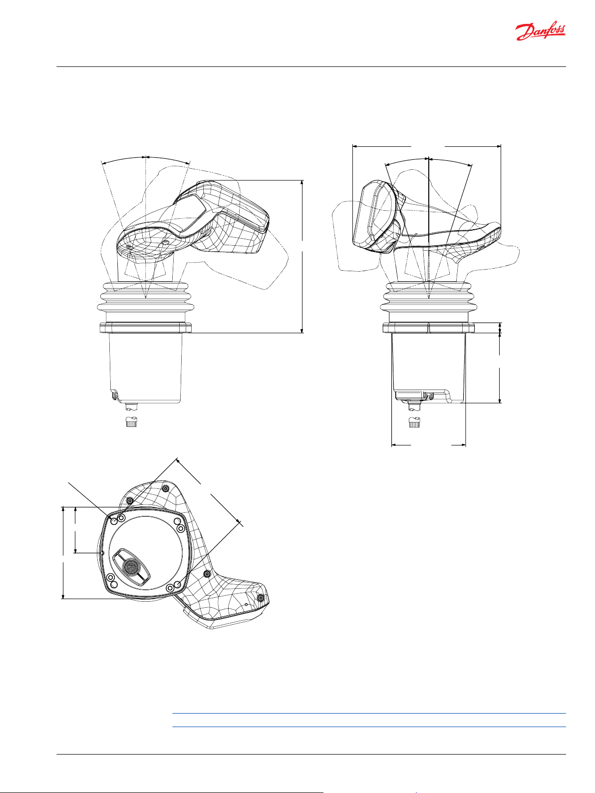
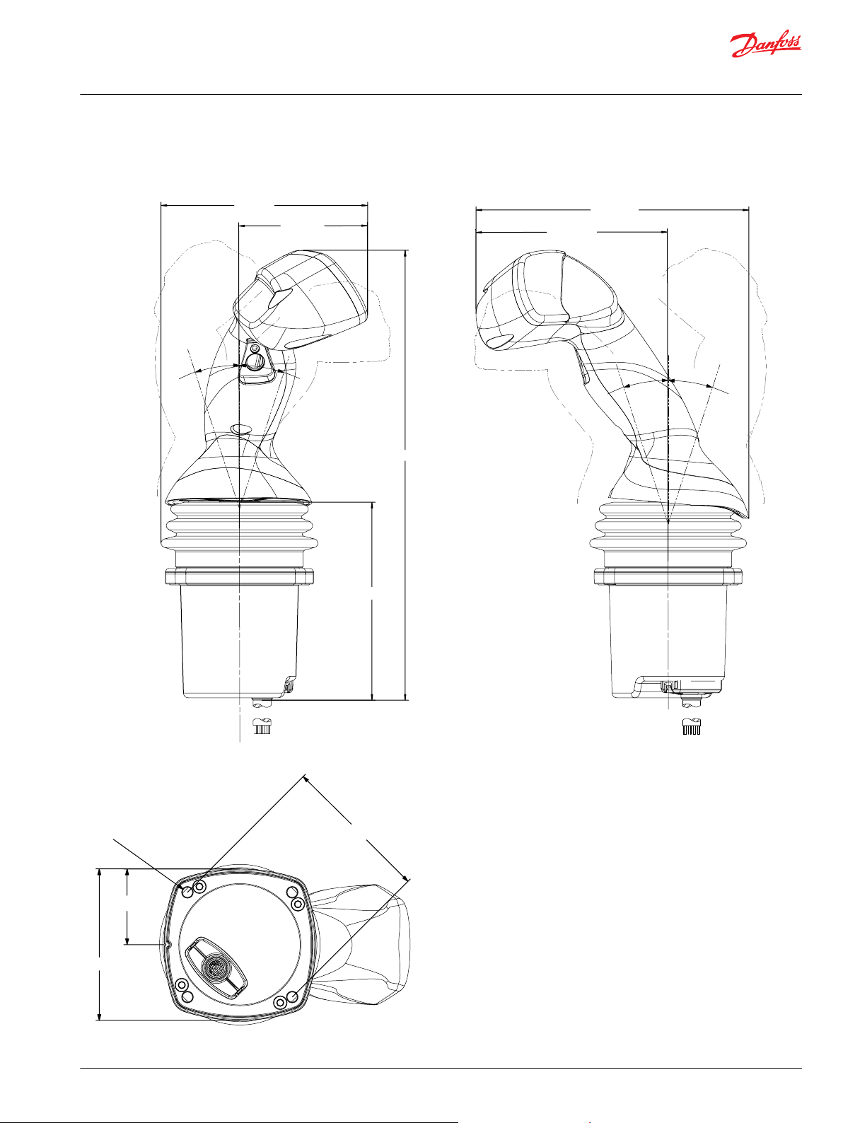
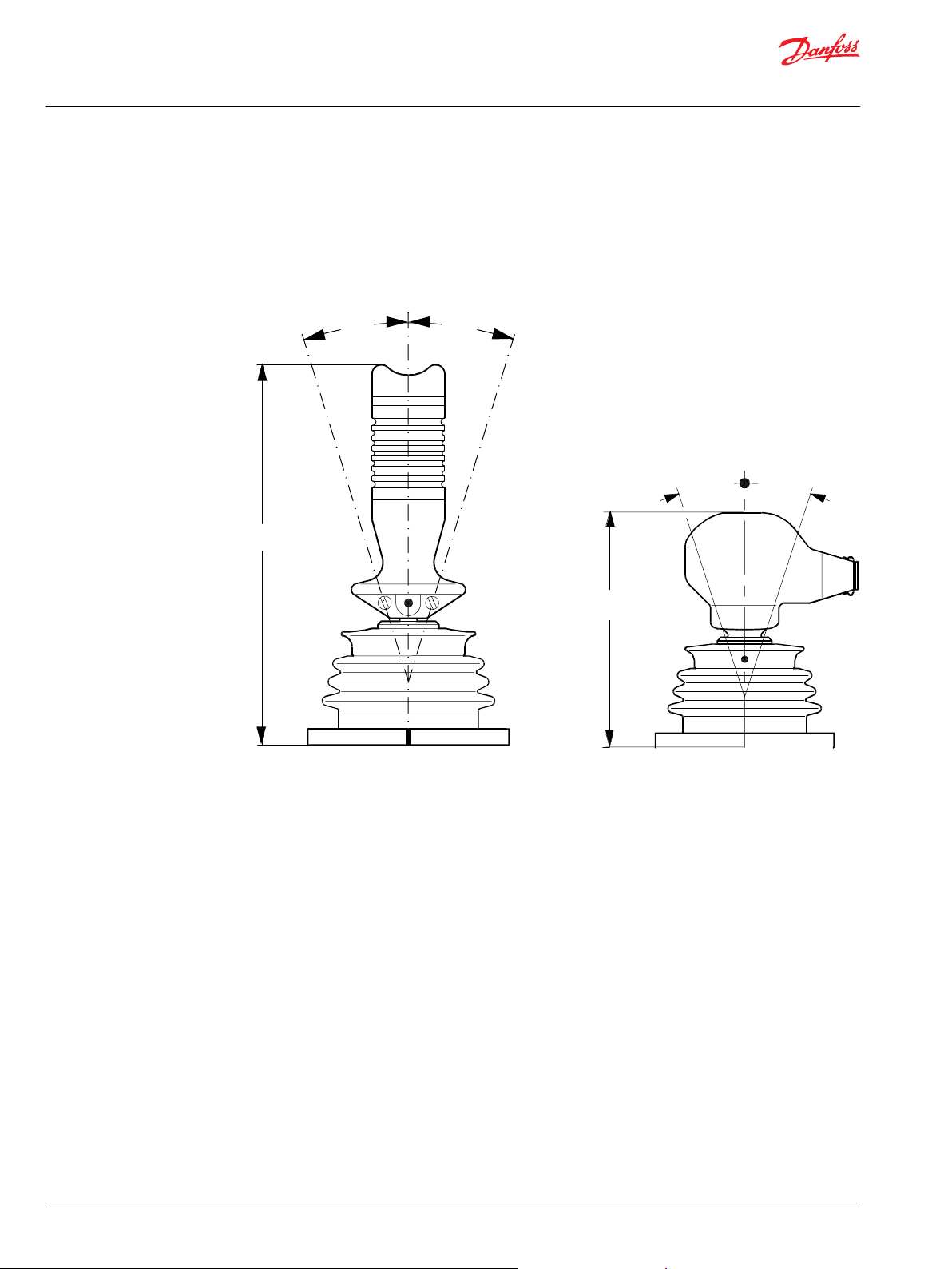
HR1, HP1 grip
Dimensions
HR1 (horizontal) grip with base dimensions in millimeters [inches]
Ten total grip functions
•
Front plate: Up to five functions
•
Grip top side: Up to two functions
•
Grip rear side: Up to three functions
Push button = 1 function, roller/rocker/FNR/Operator Presence Switch = 2 functions
©
Danfoss | October 2020 BC171886484518en-001305 | 9
kwa1452624614146
1
2
3
L-NNNNN
R-NNNNN
L-UNNNN
R-UNNNN
L-UNUNN R-UNUNN L-PNKNN
R-PNKNN
L-YNNNN
R-YNNNN
L-UNYNN
R-UNYNN
L-UNUNY R-UNUNY
L-YYNNN
R-YYNNN
L-UNYYN
R-UNYYN
L-KNNNN R-KNNNN
L-YYYNN
R-YYYNN
L-UNYYY
R-UNYYY
L-NNKNN R-NNKNN
L-YYYYN R-YYYYN L-YYUNN R-YYUNN
L-YYYYY R-YYYYY L-YYUNY R-YYUNY
L-KNKNN R-KNKNN
L-NNYPN R-NNYPN
L-PNKNY
R-PNKNY
L-NYNNN
L-NNYNN R-NNYNN
L-NNNYN R-NNNYN
L-NNNNY R-NNNNY
R-NYNNN
H1=Y H1=Y
H1=U
H1=U H1=U H1=U H1=U
H3=Y H3=Y
H3=U H3=U
H1=U H1=U
H5=Y H5=Y H5=Y H5=Y
H2=Y
H3=Y H3=Y
H4=Y H4=Y
H5=Y H5=Y
H2=Y
H3=U H3=U
H1=U H1=U H1=K H1=K
H3=Y H3=Y
H4=Y H4=Y
H1=U
H3=U H3=U
H3=U H3=U
H1=U
H3=Y
H2=Y H2=Y
H1=Y H1=Y
H3=Y
H4=Y H4=Y
H5=Y H5=Y
H1=U H1=U H1=U H1=U H1=U
H1=Y H1=Y
H2=Y H2=Y
H1=Y
H3=Y H3=Y
H1=Y
H2=Y H2=Y
H1=Y
H3=Y H3=Y
H4=Y H4=Y
H1=Y
H2=Y H2=Y
H1=Y
H3=Y H3=Y
H4=Y
H5=Y H5=Y
H5=Y H5=Y
H4=Y
H1=Y
H1=Y H1=Y
H2=Y H2=Y
H2=Y H2=Y
H4=P
H3=Y
H4=P
H3=Y
H3=K
H3=K
H1=K H1=K
H3=K
H3=K
H3=K
H3=K H3=K
H3=K
kwa1452624730259
Technical Information
JS1 Heavy Duty Joysticks
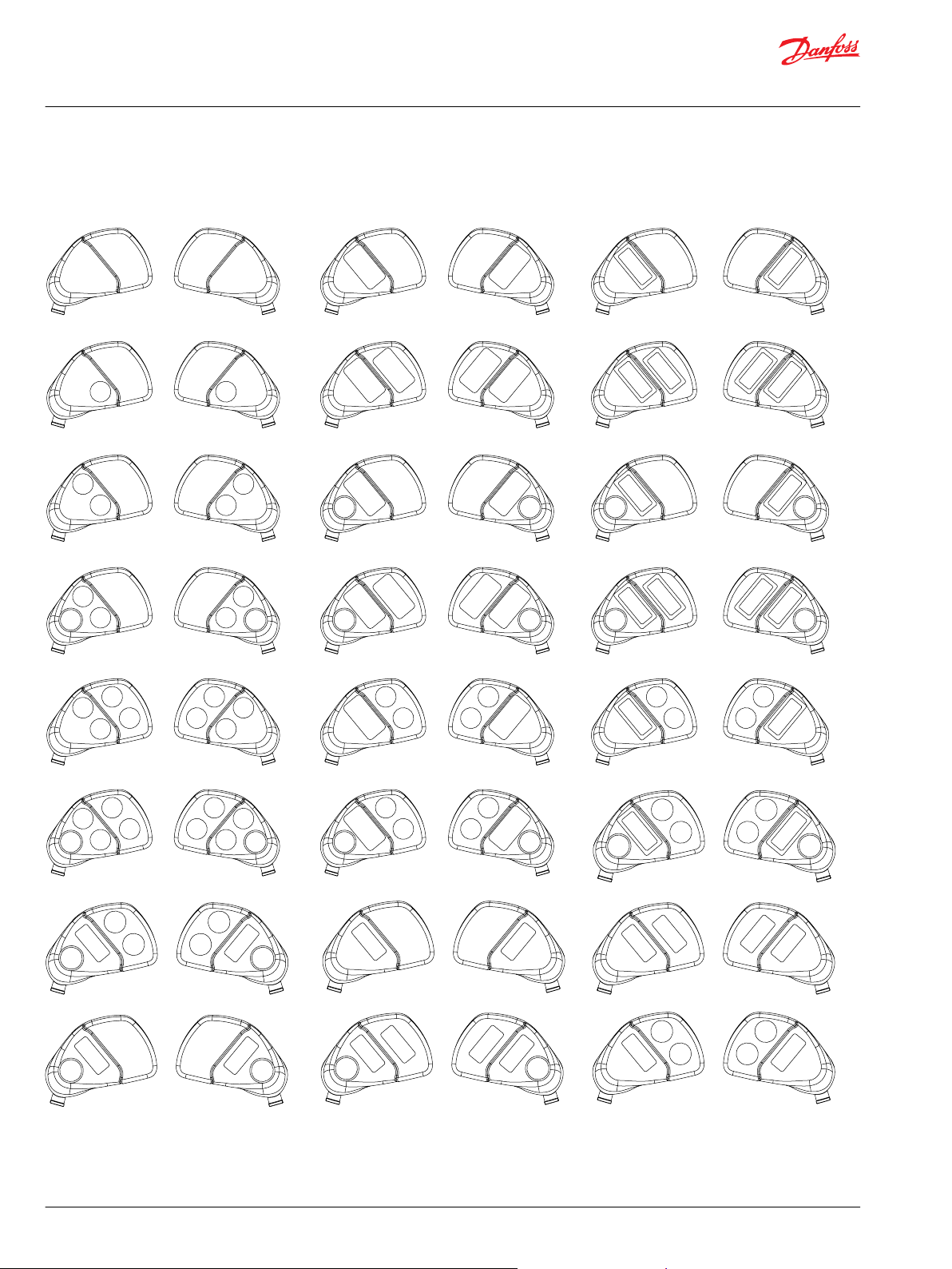
HR1, HP1 grip
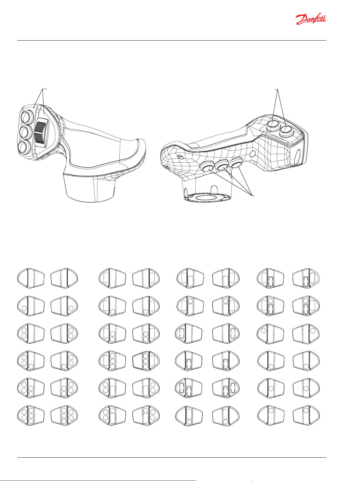
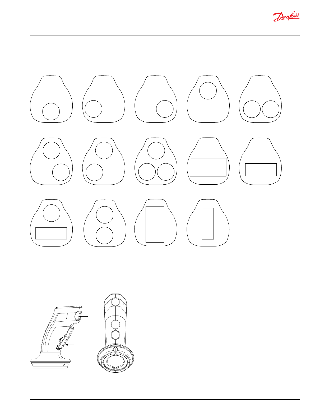
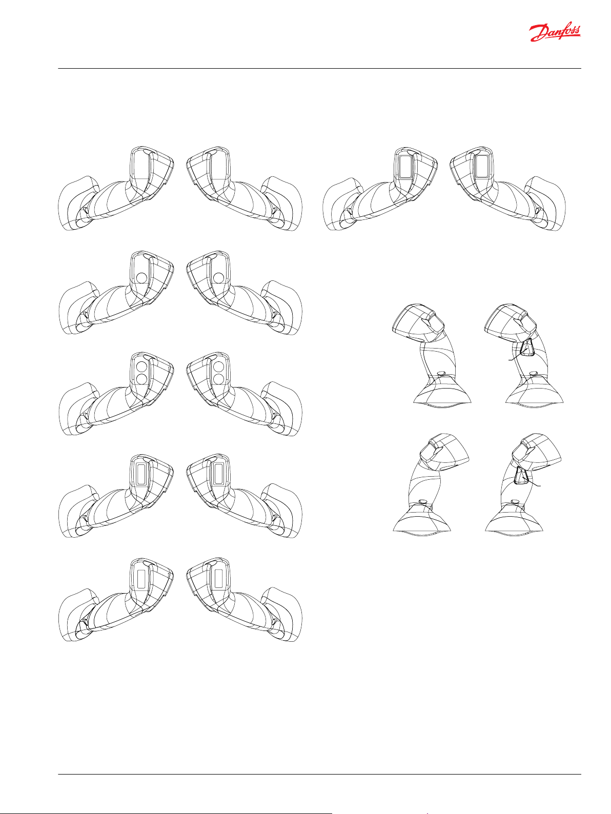
Function overview
HR1 grip function overview
1. Faceplate finger function location
2. Cover finger function location
3. Base finger function location
Faceplate options
HR1 grip faceplate options
10 | © Danfoss | October 2020 BC171886484518en-001305
L-#####NN
R-#####NN L-#####YY
R-#####YY
L-#####YN
R-#####YN L-#####KN
R-#####KN
L-#####NY
R-#####NY L-#####UN
R-#####UN
kwa1452624768604
H7=Y
H6=K
H6=U H6=U
H6=Y H6=Y
H7=Y H7=Y
H6=K
H7=Y
H6=YH6=Y
Technical Information
JS1 Heavy Duty Joysticks
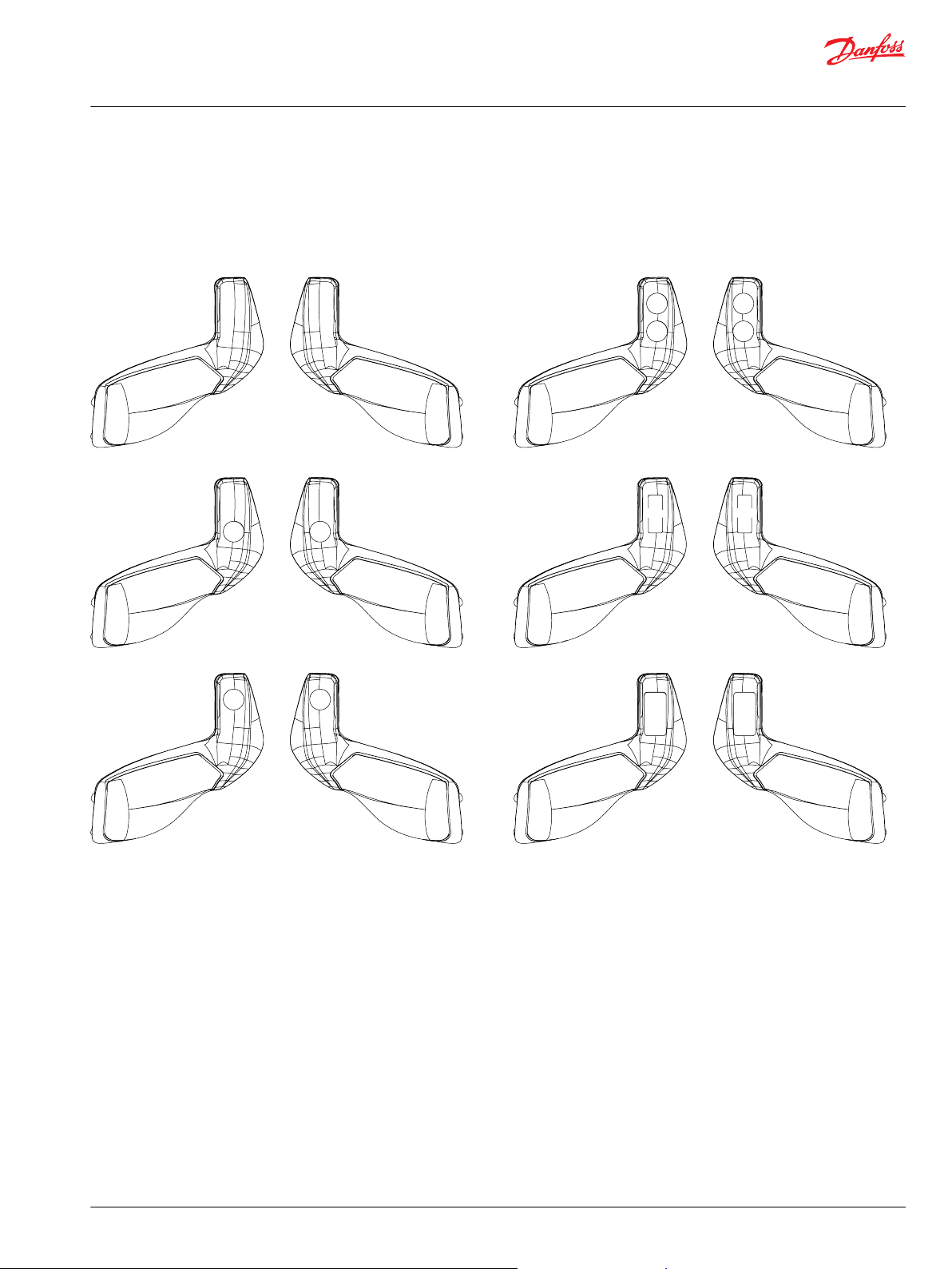
HR1, HP1 grip
Cover options
HR1 grip cover options
Related reference
©
Danfoss | October 2020 BC171886484518en-001305 | 11
L-#######NNN
R-#######NNN
L-#######YYN
R-#######YYN
L-#######YNN
R-#######YNN
L-#######NYY
R-#######NYY
L-#######NYN
R-#######NYN
L-#######YYY
R-#######YYY
L-#######NNY
R-#######NNY
L-#######DNN
R-#######DNN
H8=Y H8=Y
H9=Y H9=Y
H10=Y
H8=D
H8=D
H9=Y H9=Y
H9=YH9=Y
H10=Y
H10=Y
H10=Y
H10=Y
H10=Y
H8=Y
H8=Y
H8=Y
H8=Y
H9=Y
H9=Y
kwa1452624813199
Technical Information
JS1 Heavy Duty Joysticks
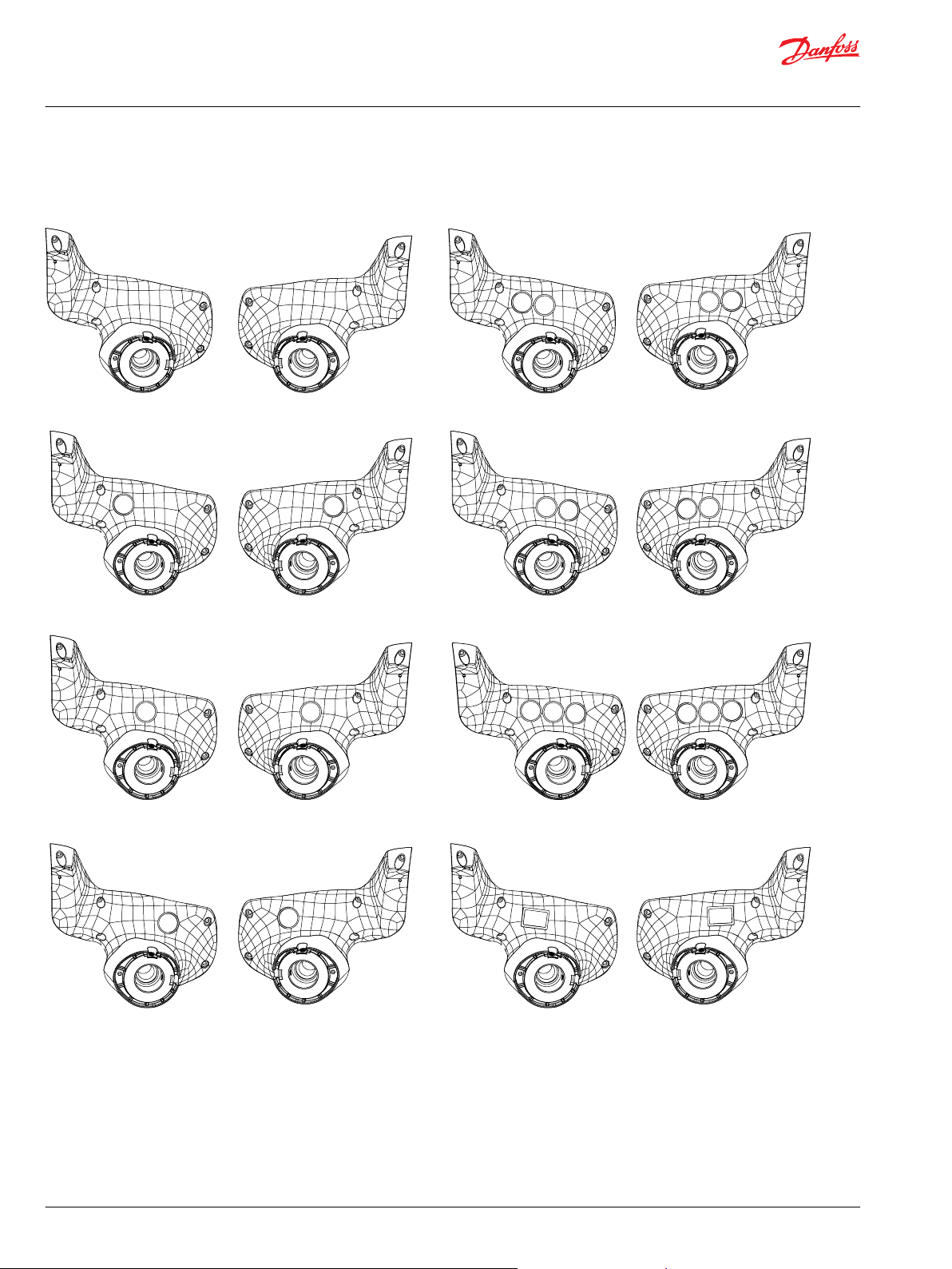
HR1, HP1 grip
Base options
HR1 grip base options
12 | © Danfoss | October 2020 BC171886484518en-001305
Technical Information
JS1 Heavy Duty Joysticks
ST2, SP2 grip
The ergonomic ST2, SP2 grip is designed to provide a solution to grip applications requiring an operator
presence function. The profile of the ST2, SP2 grip, ensures that the operator’s fingers are always close to
the buttons to minimize operator fatigue and maximize functional control.
For applications that require high ingress protection (IP66) select the SP2 grip. For more information see
F2 ordering code under Grip model code.
©
Danfoss | October 2020 BC171886484518en-001305 | 13
Ø 72.60 [2.86]
68.80 [2.71]
10.00 [0.39]
Ø 75.80 [2.98]
18° 18°
18° 18°
166.00 [6.55]
Ø 6.00 [0.24]
88.00 ± 0.05 [3.46 ± 0.002]
45.00 [1.77]
90.00 [3.54]
kwa1433433604401
Technical Information
JS1 Heavy Duty Joysticks
ST2, SP2 grip
Dimensions
ST2 grip with base dimensions in millimeters [inches]
Five total grip functions
•
Front plate: Up to three functions
•
Pointer finger side: one function (if nothing is placed in position 2)
•
Grip rear side: Up to two functions or an Operator Presence switch
Push button = 1 function, roller/rocker/FNR/Operator Presence Switch = 2 functions
14 | © Danfoss | October 2020 BC171886484518en-001305
Y+N YNN NYN NNY YYN
NYY YNY YYY PNN KNN
KNY Y+Y NPN NKN
kwa1442519181260
H1=Y+
H3=Y
H1=Y H2=Y
H1=Y
H2=Y
H3=Y H3=Y H3=Y
H3=Y
H1=K
H3=Y
H2=Y
H2=P H2=K
H2=Y
H1=P
H1=K
H1=Y H1=Y
H1=Y+
H8=0
H6=Y
H6=Y
H8=Y
H9=Y
kwa1467052019867
Technical Information
JS1 Heavy Duty Joysticks
ST2, SP2 grip
ST2—Faceplate options
ST2 grip faceplate options
Related reference
Cover options
ST2 grip cover options
©
Danfoss | October 2020 BC171886484518en-001305 | 15

Technical Information
JS1 Heavy Duty Joysticks
PR2, PP2 grip
The PR2, PP2 grip is the successor of the Prof 1. The grip features a forward-leaning, curved, ergonomic
shape. The textured surface and movement pattern of the grip is designed for a comfortable user
interface and maximum functional control.
For applications that require high ingress protection (IP66) select the PP2 grip. For more information see
F2 ordering code under Grip model code.
16 | © Danfoss | October 2020 BC171886484518en-001305
90.00 [3.54]
45.00 [1.77]
Ø 6.00 [0.24]
88.00 [3.46]
190.00 [7.48]
18° 18°
Ø 76.00 [2.98]
10.00 [0.39]
68.80 [2.71]
Ø 72.60 [2.86]
kwa1433433677109
Technical Information
JS1 Heavy Duty Joysticks
PR2, PP2 grip
Dimensions
PR2 grip with base dimensions in millimeters [inches]
Twelve total grip functions
•
Front plate: Up to five functions
•
Grip left side: Up to three functions
•
Grip right side: Up to two functions
•
Grip rear side: Up to two functions or an OPS
Push button = 1 function, roller/rocker/FNR/Operator Presence Switch = 2 functions
©
Danfoss | October 2020 BC171886484518en-001305 | 17
NNNNN NYNNN YYNNN YYYNN YYYYN YYYYY YNNYY NYYNN NYYNY
NNNYN NNYNN YNNNN YNYYN YNNYN NYYYN YYNYN NNNNY NNYYN
YPNYN YYFNN NNPNN NNPNY YYPNN YYPNY PNNNN NPNNN NNNPN
NYPNN PNYYN P NYNN NYYPN P NYYY YP NYY NYYPY PNPNN NPNPN
NPNPY PNP NY PNF NY NFNPY NNNPY FNFNY FNPNY NYNPY NNYPY
NNFNN FNYYY
KNPNY KNPNN
FNFNN NNFNN FNYYN KNNNN FNNNN KNYNY KNYYY
H2=Y
H2=Y
H3=Y
H3=Y
H3=F
H2=Y
H3=Y
H3=F H1=F H1=F H1=F
H3=F
H3=F H3=F H1=FH1=K H1=K
H1=K
H1=K
H2=Y H3=Y H2=Y
H1=Y
H1=Y
H1=Y
H1=Y
H1=Y
H1=Y
H1=Y
H1=YH4=Y
H4=Y
H4=Y
H1=Y
H3=Y
H4=Y
H4=Y
H3=Y H2=Y
H2=YH2=Y
H2=P H2=Y
H2=Y
H2=Y
H3=Y
H2=Y
H3=Y H2=Y
H1=Y
H5=Y
H3=Y
H3=Y
H2=Y
H5=Y
H5=Y
H5=YH5=Y
H5=Y H5=Y
H5=Y
H3=Y
H4=Y
H5=Y
H5=Y H5=Y
H5=Y H5=Y H5=Y H5=Y H5=Y H5=Y H5=Y
H4=Y H1=Y
H5=Y
H4=Y
H4=Y
H1=Y
H4=Y H4=Y
H4=Y
H2=P
H4=P
H3=PH3=PH3=P
H3=P
H3=P
H1=P
H1=P
H4=P
H4=P H4=P H4=P H4=PH4=P
H4=P H4=P
H2=P
H3=Y H3=Y
H3=Y H3=Y
H4=Y
H4=Y
H4=Y
H1=Y
H5=Y H5=Y H5=Y
H1=P
H2=P
H2=P
H2=Y H2=Y
H1=P H1=PH3=P
H1=P
H2=F H2=Y H3=Y
H3=Y
H3=Y H3=Y
H4=Y
H1=PH3=P
H3=P
H1=K
H3=P
H3=P
H3=F H1=F H1=F
kwa1442519652547
Technical Information
JS1 Heavy Duty Joysticks
PR2, PP2 grip
Faceplate options
PR2 faceplate options
18 | © Danfoss | October 2020 BC171886484518en-001305
Related reference
H6=Y
H7=Y
H8=Y
H9=Y
H11=Y
H6=U
H12=Y
H12=U
H10=K
H10=Y
H6=Y
Technical Information
JS1 Heavy Duty Joysticks
PR2, PP2 grip
Cover options
PR2 cover options
H6 alternate position when configuring Prof1 replacement
When this option is used, grip is limited to 8 functions.
©
Danfoss | October 2020 BC171886484518en-001305 | 19
Technical Information
JS1 Heavy Duty Joysticks
ST7, SP7 grip
The multifunction, ambidextrous, ergonomic ST7, SP7 grip is designed for a comfortable user interface
and maximum functional control. The ST7, SP7 grip features a modular design that allows switch location
flexibility.
The ST7, SP7 grip is available with combinations of up to 11 push-button switches, or a mix of
proportional, FNR, rocker switches, and an Operator Presence switch.
For applications that require high ingress protection (IP66) select the SP7 grip. For more information see
F2 ordering code under Grip model code.
20 | © Danfoss | October 2020 BC171886484518en-001305
190.00 [7.48 ]
18 °
18 °
18° 18°
Ø 75.80 [2.98]
10.00 [0.39]
68.80 [2.71]
Ø 72.60 [2.86]
Ø 6.00 [0.24]
88.00 [3.46]
45.00 [1.77]
90.00 [3.54]
kwa1452886441007
Technical Information
JS1 Heavy Duty Joysticks
ST7, SP7 grip
Dimensions
ST7 grip with base dimensions in millimeters [inches]
©
Danfoss | October 2020 BC171886484518en-001305 | 21
NNNNNN
NYYNNN
NYYPNN
NYYPYN YNNYNN
NPNPYN
KNPNNN KNPNYN PNYYYN
NNNPNN
KNNNNN NNKNNN
PNPNNN
PNPNYN
NPNPNN
PNYNNN
YYPNYN
NNNNNY
YYYYYN
YYYYNN
PNNNNN NNPNNN
NPNNNN
NNNNYNNNNYNNNNYNNN
NYNNNN
YNNNNN
jbf1473988482902
H1=Y
H6=Y
H2=Y H3=Y
H3=Y H2=Y
H4=Y
H4=Y H1=Y
H1=K
H1=K H1=K
H3=K
H1=P
H1=P H1=P
H1=PH3=PH1=P
H2=P
H4=P
H3=P
H3=P H3=P
H3=YH2=YH3=Y
H1=YH4=Y
H3=Y H2=Y H3=Y H2=Y H3=Y H2=Y
H4=Y H1=Y
H3=P
H3=P
H2=P
H4=P
H2=P
H4=P
H4=P H4=P
H3=Y H2=Y
H4=Y H1=Y
H5=Y
H5=Y
H5=Y
H5=YH5=Y
H5=Y
H5=Y
H5=Y
kwa1470173173764
Y+NNNN
YYYYYY YYPN+Y PNYYY+PNY+NNY+PNNN
NYY+NN YYY+NN YYYY+Y YYYYY+YYYY+N
H1=Y+
H3=Y H2=Y
H3=Y H2=Y
H5=Y
H6=Y
H4=Y H1=Y
H3=P H1=Y H3=Y H1=P H3=P
H2=Y H3=Y
H6=Y H5=Y
H1=Y H4=Y
H1=P
H3=Y
H3=Y
H2=Y
H2=Y H2=Y
H2=Y
H1=Y
H1=Y
H6=Y
H5=Y
H3=Y
H3=Y
H1=Y
H1=Y
H4=Y H4=Y
H4=Y
Technical Information
JS1 Heavy Duty Joysticks
ST7, SP7 grip
ST7—Faceplate options
ST7 grip faceplate options
ST7 grip faceplate customer specified options
22 | © Danfoss | October 2020 BC171886484518en-001305
H7=Y
H8=Y
H9=Y
H10=Y H11=Y
H8=O H8=O
kwa1470173162014
Technical Information
JS1 Heavy Duty Joysticks
ST7, SP7 grip
Cover options
ST7 cover options
©
Danfoss | October 2020 BC171886484518en-001305 | 23
Technical Information
JS1 Heavy Duty Joysticks
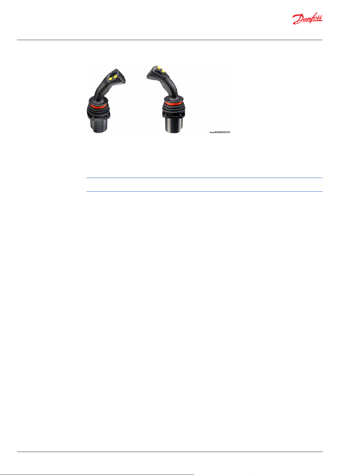
PR7, PP7 grip
The ergonomic PR7, PP7 left and right hand grips, with easy-to-use finger tip switches, are designed for
ease of access to push-button, trigger switches and proportional grip function manipulation for a
comfortable user interface and maximum functional control.
The PR7, PP7 grip features quicker adaptability, especially for new and complex machines, maximizing
productivity in all operating conditions.
For applications that require high ingress protection (IP66) select the PP7 grip. For more information see
F2 ordering code under Grip model code.
24 | © Danfoss | October 2020 BC171886484518en-001305
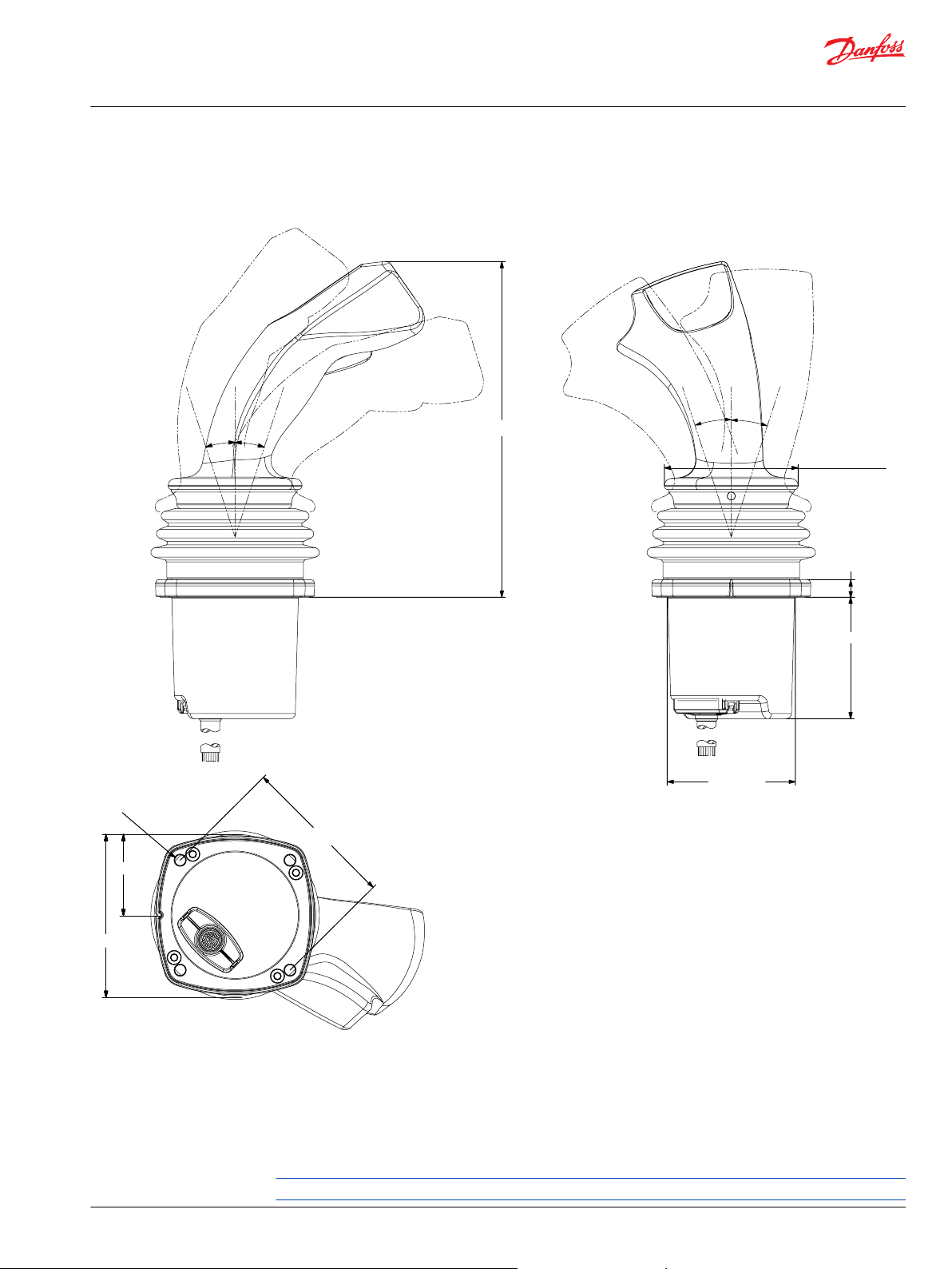
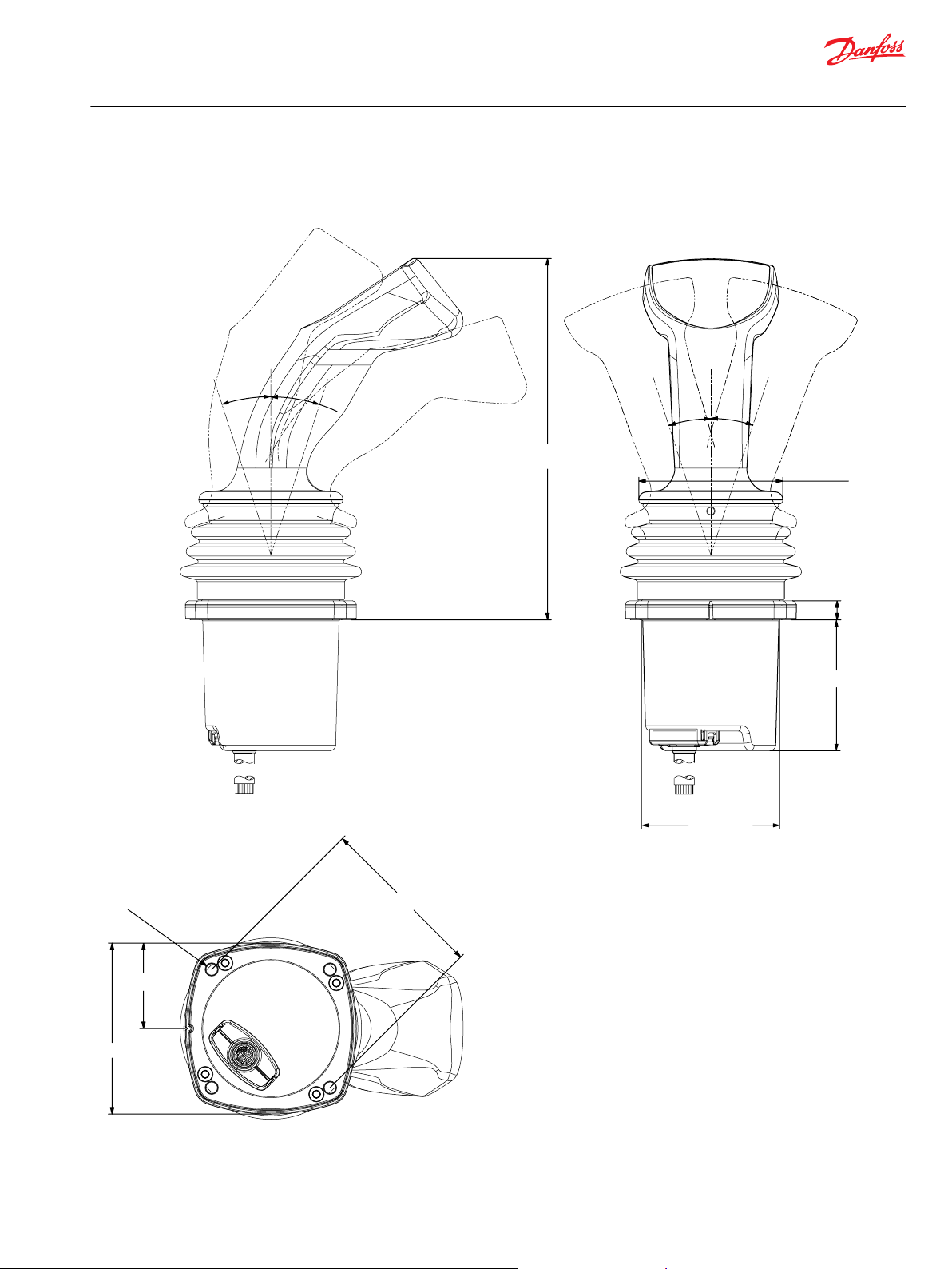
Ø 6.00 [0.24]
88.00 ± 0.05 [3.46 ± 0.002]
45.00 [1.77]
90.00 [3.54]
18° 18°
18° 18°
kwa1452895556296
126 [4.96]
78.00 [3.07]
274.00 [10.79]
121.00 [4.76]
166.00 [6.53]
117.00 [4.60]
Technical Information
JS1 Heavy Duty Joysticks
PR7, PP7 grip
Dimensions
PR7 grip with base dimensions in millimeters [inches]
©
Danfoss | October 2020 BC171886484518en-001305 | 25
L-NNNNN R-NNNNN L-NUNNN R-NUNNN L-NKNNN R-NKNNN
L-NYNNN R-NYNNN L-NUNUN R-NUNUN L-NKNKN R-NKNKN
L-NYYNN R-NYYNN L-YUNNN R-YUNNN L-YKNNN R-YKNNN
L-YYYNN R-YYYNN L-YUNUN R-YUNUN L-YKNKN R-YKNKN
L-NYYYY R-NYYYY L-NUNYY R-NUNYY L-NKNYY R-NKNYY
L-YYYYY R-YYYYY L-YUNYY R-YUNYY
H2=U H2=U
H2=K
H2=K
H2=Y
H2=Y
H2=U
H4=U
H2=U
H2=K
H4=K
H2=K
H2=K
H1=Y
H2=K
H1=Y
H4=K
H4=U
H2=UH2=U
H1=Y
H1=Y
H3=Y
H2=Y
H3=Y
H2=Y
H3=Y
H3=Y
H1=Y
H1=Y
H2=Y
H2=Y
H1=Y H1=Y
H2=U
H2=U
H4=U
H4=U
H1=Y
H1=Y
H2=K
H2=K
H4=K H4=K
H5=Y
H5=Y
H2=K
H2=K
H4=Y
H4=Y
H5=Y
H5=Y
H2=U H2=U
H4=Y
H4=Y
H5=Y
H5=Y
H2=U
H2=U
H4=Y
H4=Y
H5=Y
H5=Y
H2=Y
H2=Y
H3=Y
H3=Y
H4=Y
H4=Y
H5=Y
H5=Y
H2=Y
H2=Y
H3=Y
H3=Y
H4=Y
H4=Y
H1=Y H1=Y
H1=Y
H1=Y
H1=Y
H1=Y
H2=K
H2=K
H5=Y H5=Y
H4=Y
H4=Y
L-YKNYY R-YKNYY
H1=Y
H1=Y
H2=F
H2=F
H5=Y
H5=Y
H4=Y
H4=Y
L-YFNYY R-YFNYY
L-NFNNN R-NFNNN
L-NFNFN R-NFNFN
H2=F
H4=F
H4=F
H2=F
H2=F
H2=F
L-YFNNN R-YFNNN
L-YFNFN R-YFNFN
H2=F
H1=Y
H2=F
H1=Y
H2=F
H4=F
H1=Y
H2=F
H1=Y
H4=F
L-NFNYY R-NFNYY
H5=Y
H2=F
H4=Y
H5=Y
H4=Y
H2=F
kwa1454539607113
Technical Information
JS1 Heavy Duty Joysticks
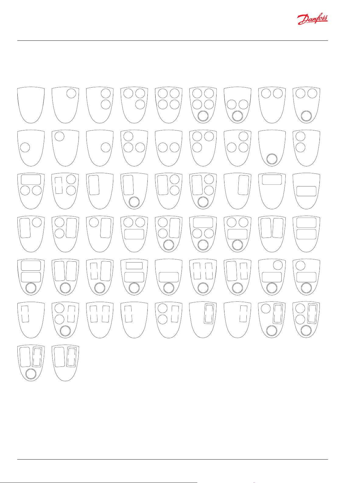
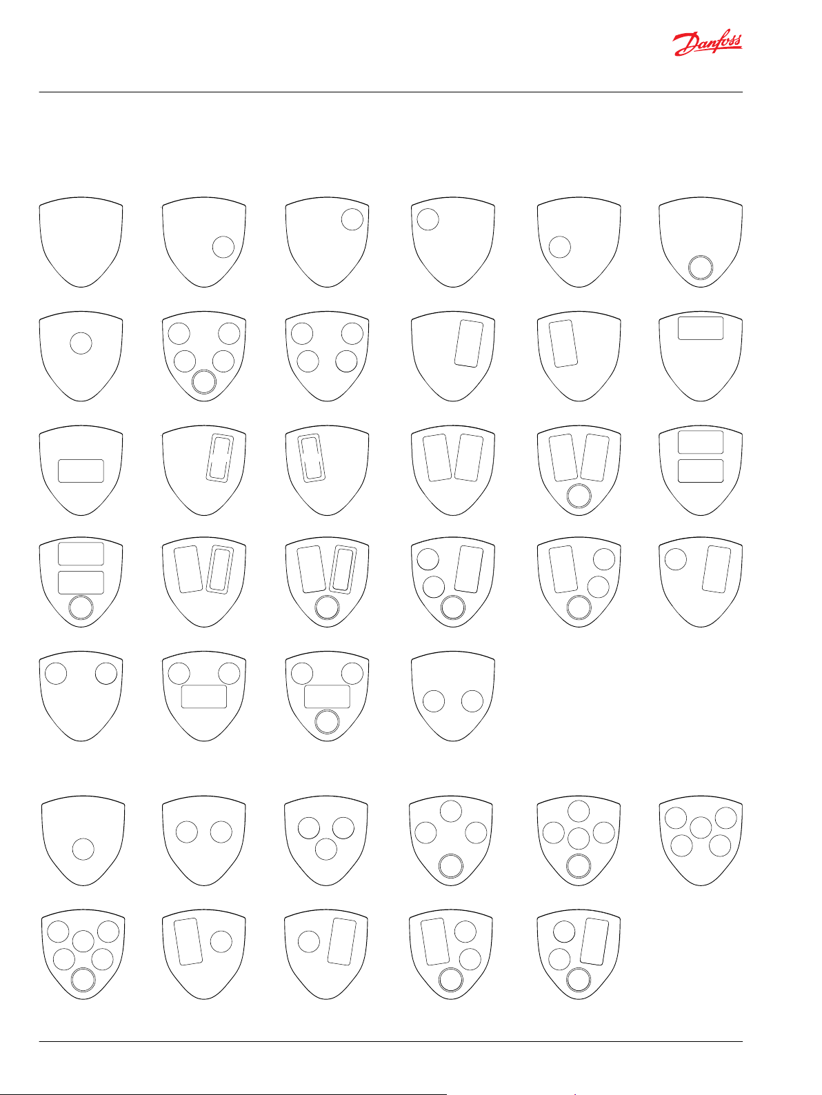
PR7, PP7 grip
Faceplate options
PR7 faceplate options
26 | © Danfoss | October 2020 BC171886484518en-001305
L-#######N
L-#####NN# R-#####NN#
L-#####YN# R-#####YN#
L-#####YY# R-#####YY#
L-#####KN# R-#####KN#
L-#####FN# R-#####FN#
L-#####QN# R-#####QN#
R-#######N R-#######E
L-#######A
H8=A
H8=E
H6=F
H6=K
H7=Y
H6=Y
H6=Y H6=Y
H6=Q H6=Q
H7=Y
H6=Y
H6=K
H6=F
kwa1454542269293
Technical Information
JS1 Heavy Duty Joysticks
PR7, PP7 grip
Cover options
PR7 cover options
©
Danfoss | October 2020 BC171886484518en-001305 | 27
18°
18°
18°
18°
198.00 [7.80]
139.00 [5.47]
kwa1433434519003
A B
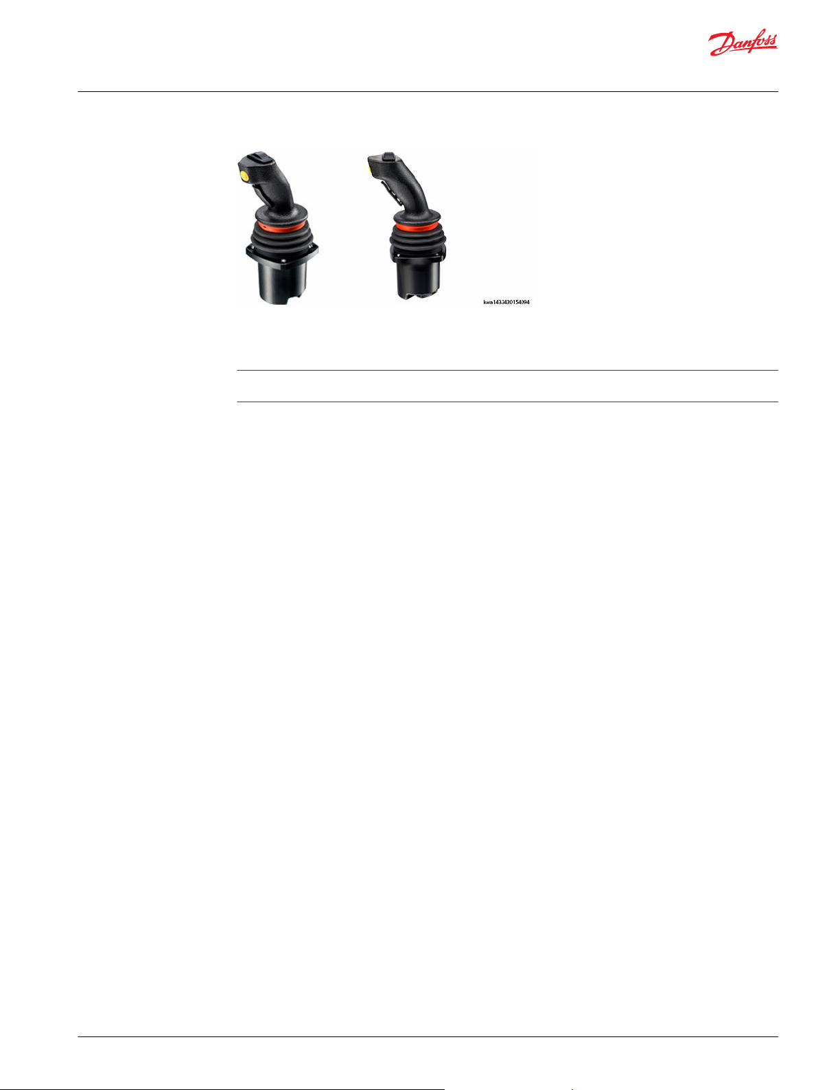
Technical Information
JS1 Heavy Duty Joysticks
Compatible grips
Dimensions
Other Danfoss grips compatible with the JS1 heavy duty base are Prof1, PVRE and PVRET which are
generally used together with valves. For more information regarding Prof1, PVRE and PVRET grips please
reference Prof 1, PVRE and PVRET Joystick Technical Information Manual, BC152886484305.
PVRE; and PVRET grips dimensions in millimeters [inches]
Grip only sales and service options
28 | © Danfoss | October 2020 BC171886484518en-001305
A
B STT grip: IP54
All Danfoss grips are sell-able items. Go to Product configuration model code on page 61 and Grip model
code for developing grips.
All finger functions are marked with colored tape to indicate their position on the grip. The grip locations
will match to a location on the printed circuit board.
STN grip, no switch: IP65
STS grip with rocker switch: IP42
STP grip with proportional: IP65
Technical Information
JS1 Heavy Duty Joysticks
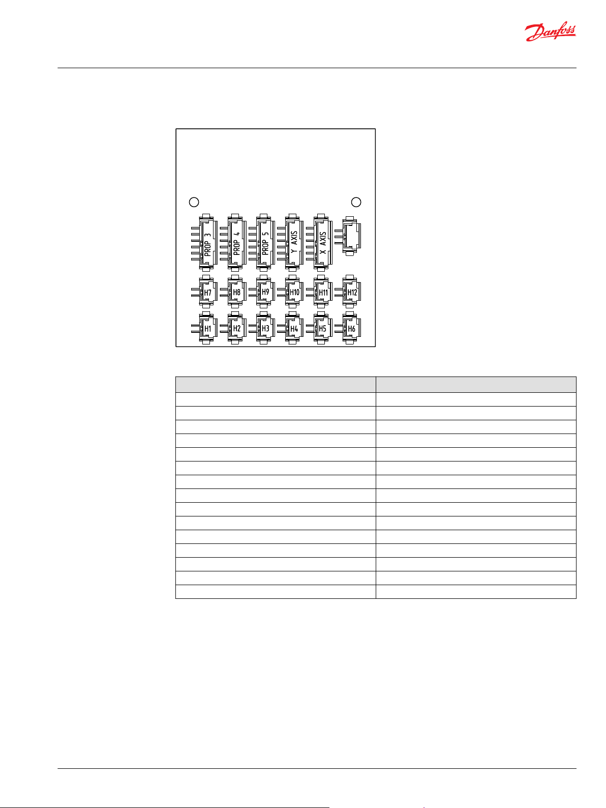
Compatible grips
Printed circuit board
Plug in connectors accordingly
Position Tape color
H1 Red
H2 Yellow
H3 Blue
H4 Black
H5 White
H6 None
H7 Green
H8 Blue/Black
H9 Yellow/Black
H10 Yellow/Red
H11 White/Red
H12 White/Green
Prop 3 N/A
Prop 4 Yellow
Prop 5 Red
©
Danfoss | October 2020 BC171886484518en-001305 | 29
24.00 ± 0.10 [0.94 ± 0.004]
21.00 ± 0.30 [0.83 ± 0.011]
3.30 [0.13]
5.50 [0.22]
Ø 88.00 [3.46]
Ø 74.00 [2.91]
4x Ø 5.50 [0.22]
90.00 [3.54]
37.50 [1.48]
130.30 [5.13]
68.8
[2.71]
132.30
[5.21]
39.40
[1.55]
kwa1433458535145
1
62.23 [2.45]
62.23 [2.45]
Technical Information
JS1 Heavy Duty Joysticks
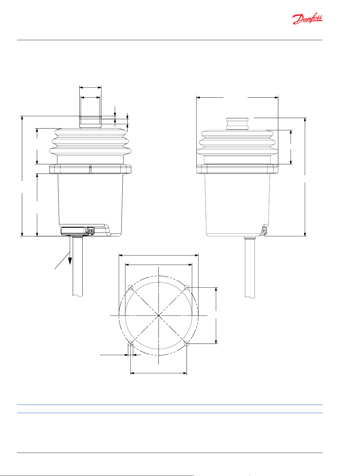
Base
Dimensions
Base dimensions in millimeter [inches]
1. Minimum clearance from the bottom of the base:
•
25.4 mm (1 in) for the one and two 6 pin connector cables (CAN output)
•
40 mm (1.6 in) for all other cables
Mounting screws have a maximum torque of 7.9 N•m (69.9 in•lbf).
30 | © Danfoss | October 2020 BC171886484518en-001305
 Loading...