

Page 1
Operating Guide
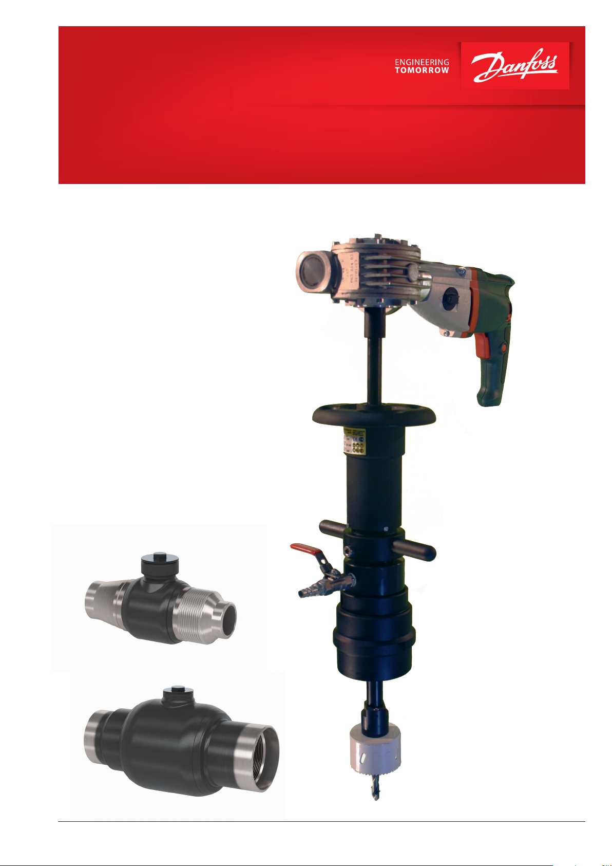
JIP Hot Tapping Machine Toolbox
JIP Hot Tapping Machine
DN 20-100
© Danfoss | 2022.03
AQ243486498056en-000302 | 1
Page 2

Operating Guide JIP Hot Tapping Machine Toolbox
1. Content
1. Content 2
2. Safety Instructions 3
2.1 General Safety Requirements 3
2.2 Safety Requirements at the Workside 4
2.3 Special Risks 5
2.4 The Signicance of Symbols used Safety 5
3. Description Danfoss Hot Tapping Machine Toolbox 6
3.1 Area of Use 6
3.2 Specications of the Danfoss Drilling Device 6
3.3 Danfoss JIP Hot Tap Valves with Hot Tapping Machine Toolbox 8
4. Operational Instructions 9
4.1 Branch Preparations before the Hot Tapping 9
4.1.1 Removing the Insulation 9
4.1.2 Adjusting the Hot Tap Valve 9
4.1.3 Welding of the Hot Tap Valve to the Main Line 9
4.1.4 Testing the Valve 10
4.2 Assembly of the Drilling Device 11
4.2.1 Assembly of the shaft for hole saws >32 mm 11
4.2.2 Assembly of the shaft for hole saws < 32 mm 12
4.2.3 Assembly of the Danfoss JIP Adapter Socket 12
4.2.4 Assembly of the Device to the Hot Tapping Valve 13
4.2.5 Installing the Feed Unit 13
4.2.6 Installing the Driving Unit 14
4.3 The Hot Tapping Process 15
4.3.1 Pressure Test 15
4.3.2 Starting the Driling Process 16
4.3.3 Adjusting the Feed 17
4.3.4 Releasing the Feed Unit 18
4.3.5 Closing the Valve and Releasing the Pressure 18
4.3.6 Disassembling the Machine 19
4.4 Creating the New Branch 19
4.5 Maintanance Plan and Spare Part List 20
4.6 Using the Chain Block 23
Page
Attachments:
A1 Safety Instructions in Regards to the Electrical Driving Unit 24
2 | AQ243486498056en-000302
© Danfoss | 2022.03
Page 3

Operating Guide JIP Hot Tapping Machine Toolbox
2. Safety Instructions
The user is well adviced to follow the safety instructions given in this manual. No warranty is
given for incorrect usage of the equipment or applications outside the scope of the Danfoss user
manuals!
If any questions occur or if you are unsure about certain aspects regarding the Danfoss hot
tapping machine toolbox, please don't hesitate to contact local Danfoss for support. It is
recommended to limit the pressure in the system to 12 bar during the operation.
2.1. General Safety Requirements
In the following chapters, the general and specic saftey instructions for the Danfoss hot tapping machine toolbox
are given and explained. The user is well adviced to read, understand and follow these instructions carefully.
Only qualied and trained person is allowed to execute hot tapping works with the Danfoss hot tapping tool.
Among the operators, there should be a control system to ensure that the skills and knowledge of the right
operation procedures are known and respected by all the working person taking part in hot tapping works. This
user manual has to be always available during the drilling works.
It is not allowed to use the device outside the application area described in this user manual without the
permission of hot tapping toolbox device manufacturer Danfoss.
Be aware that additional requirements can be given at the specific worksite.
For a safe usage of the equipment is essential to take the following general points into account:
• Never use the machine without being aware of the hazards. Take all the aspects from this user
manual and additional requirments into account.
• The staff must have the adequate skills and training in all the necessary phases of
the hot tapping work as well as in handling the equipment in question.
• Make sure that you always have a copy of this user manual with you which is available during the
hot tapping process. The Instruction may be downloaded from the manufacturer's
web-site (http://www.danfoss.com).
• The application area for this device is limited to water-based liquid uids of uid group 2
according to PED 2014/68/EU. The system parameters shall never exceed 200 °C and/or 40 bar of
pressure. See chapter 3 regarding the max. temperature and pressure this device can be used.
It is recommended to reduce the pressure in the system to 12 bar during the operation.
• Make sure that the chosen adapter including sealings is suitable for the system pressure, uid type
and temperature.
• Always make sure that the equipment is not damaged before starting the hot tapping process.
Only equipment in excellent condition shall be used.
• Only use original Danfoss spare parts for your own safety.
• Wear ear protection and a helmet.
• Wear suitable work clothes. Do not wear loose clothing or jewellery as they can be caught in moving
parts. For the protection from hot uid, wear heat resistant clothes, gloves and safety glasses.
© Danfoss | 2022.03
AQ243486498056en-000302 | 3
Page 4

Operating Guide JIP Hot Tapping Machine Toolbox
• Any technical change at the hot tapping machine is not allowed.
• Read and follow the instruction manual for using the chain block.
• Take the general accident prevention regulations into account.
• Take the instructions for motor driven machines into account. Consider the hazards from
electric current and rotating parts (attachment A1). The electric drive shall never get wet.
2.2. Safety Requirements at the Worksite
The following aspects have to always be checked at the workside before using the Danfoss drilling device.
For drillings in district heating pipelines in Germany, the AGFW directive 432 has to be considered.
• Always make sure that it is possible to close the chosen Hot Tap valve. If the shutting
mechanism cannot be closed, the only way to remove the drilling device is to empty the main line.
• Double check the size of the used hole saw and pilot drill. Check that the valve closes after the
machine is assembled.
• Familiarize yourself with the Danfoss data sheet for the chosen valve type
• Make sure that the technical parameters (pressure, temperature, uid) in the system are not
exceeding the allowed values given in this user manual for the specic application
• Check that the device is assembled correctly as shown in this user manual
• Always make a pressure test to discover possible leakages at the shut-off valve and/or the drilling
device
• Make sure that all the rotating parts move freely
• Inspect the device according to the inspection plan given in this user manual
• Unauthorized persons should not be present at the worksite during hot tapping
• Check the location of the closest network shut-off valve at the worksite
• Make sure you know all emergency contacts. This concerns the contact persons on the site, the contact
to
the device manufacturer TONISCO System Oy (http://www.tonisco.com) and the local emergency
services
• Do the visual check of the worksite and take all the necessary measurements. Clean the work
environment from all unnecessary objects. Consider the space needed for shaft removal after drilling
• Make sure that all the necessary tools and equipment is available while drilling (e.g. chain block at high
pressures)
4 | AQ243486498056en-000302
© Danfoss | 2022.03
Page 5

Operating Guide JIP Hot Tapping Machine Toolbox
2.3. Special Risks
Release of Hot Water or Steam
Hot water or steam may escape the system due to mishandling. Make sure to wear prescribed safety
equipment when working with hot tapping machine.
When releasing the pressure from the drilling device, make sure to keep a sufcient distance between you
and the release hose. Always wear heat resistant safety gloves when removing the drilling machine from the
valve.
Hazards from Rotating Parts
Note that the drill shaft and drive components rotate during drilling. Be aware of the changes in the torque at
the shaft due to the varying cutting forces.Take a xed stand and turn the feed slowly.
If the hole saw gets stuck during the drilling, reduce the feeding speed or turn the wheel slightly backwards
until the hole saw can be rotated again.
Hazards Caused by the Pressure in the Pipeline
Most of the time, there is pressure present in the pipeline that is being drilled. It is recommended to reduce
the pressure in the system to 12 bar during the operation.
If the pressure in the mainline is > 12 bar it is highly recommended to use the chain block for a safe release
of the drilling shaft. This part is not included in the toolbox but can be purchased from Danfoss as an
accessory.
Requirements for the Operator
The hot tapping device may only be operated by persons who are trained, instructed and authorized to use it.
Operator must know the operating instructions and act accordingly.
2.4. The Signicance of the Symbols used Safety
WARNING: Warns of possible serious injury or death
if instructions are not monitored
CAUTION: Displays possible personal injury or damage,
if the instructions are not monitored.
NOTICE: Provides useful information
Italics: Provides important information, which must be observed
so that the device will not be damaged
© Danfoss | 2022.03
AQ243486498056en-000302 | 5
Page 6
Operating Guide JIP Hot Tapping Machine Toolbox
3. Description Danfoss Hot Tapping Machine Toolbox
3.1 Area of Use
The Danfoss hot tapping device is intended to
accomplish new pipeline branches under pressure
in water-based heating and cooling systems at
branch dimensions DN15 - DN100.
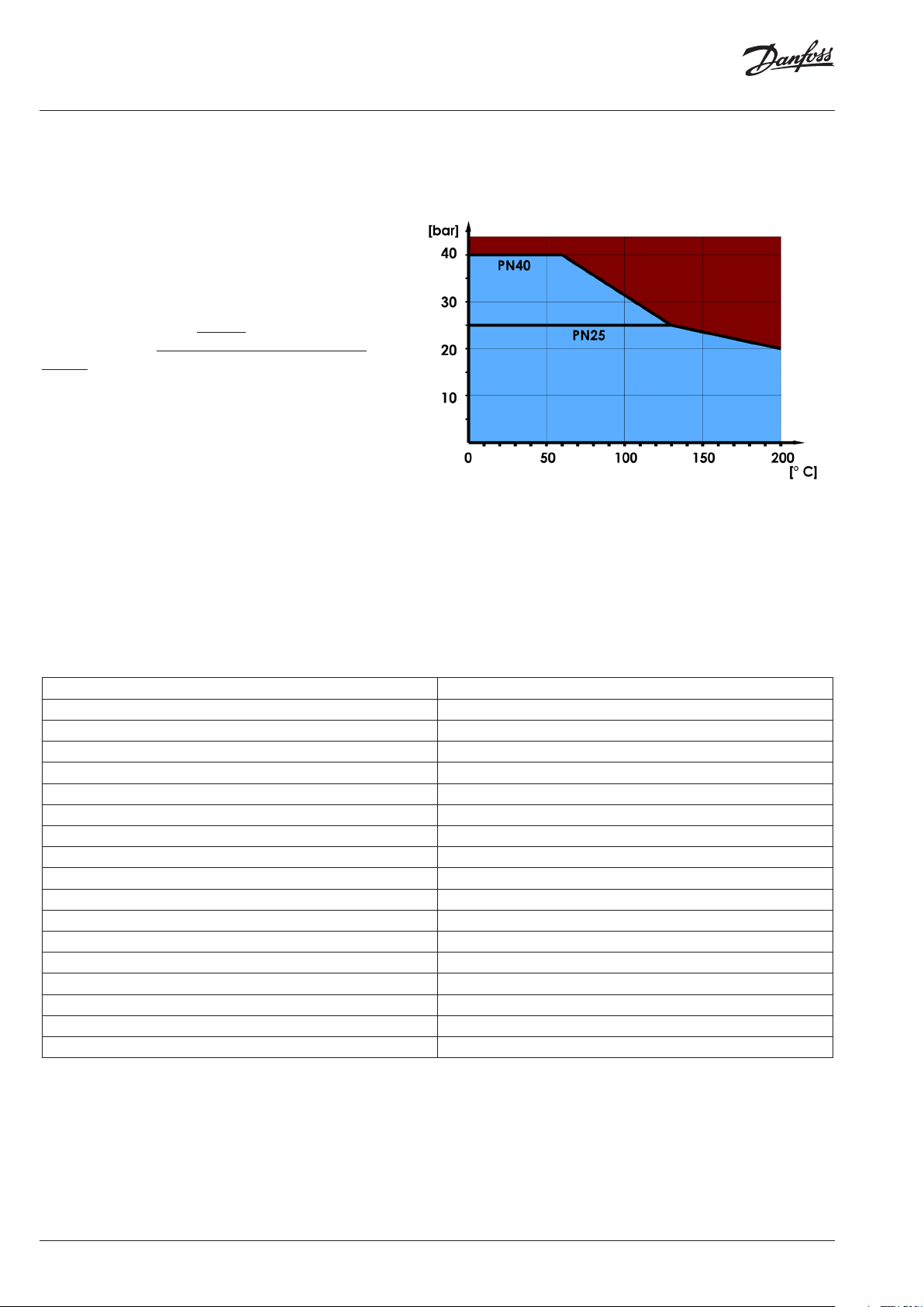
The Danfoss drilling device body is designed for
maximum pressure of 40 bar and can be used as
described in the table on the right for the class
PN40.
However, for a pressure >12 bar additional
safety requirements have to be considered when
releasing the shaft or adjusting the feed.
3.2 Danfoss Hot Tapping Toolbox specifications
Device body contains the EPDM sealings. For max. temperatures follow the P-T diagram in chapter 3.
In Danfoss toolbox, an electric drive unit is included. This user manual focuses on the electric drive unit Metabo
BE1100 with following technical specications:
Metabo BE 1100Name of Drilling Device:
42CrMo4Body Material:
1200.0000Product Number:
Bxx xx= Id. for Month, YearMarking:
1Category acc. PED 97/23/EG:
DN 15 to DN 100Branch Dimension:
Water Based Heating and Cooling SystemsArea of Use:
liquidAgregate State of the Fluid:
40 bar Max. Working Pressure:
12 barRecommended max. Pressure
60 barTest Pressure:
160 °CMax. Working Temperature:
0 °CMin Working Temperature:
EPDMSealings:
hardened steel Ø20 mmDrill Shaft:
5,4 kgWeight Without Drive:
50 mmFeed Distance Feed Wheel:
150 mmMaximum Feed Distance:
6 | AQ243486498056en-000302
© Danfoss | 2022.03
Page 7
Operating Guide JIP Hot Tapping Machine Toolbox
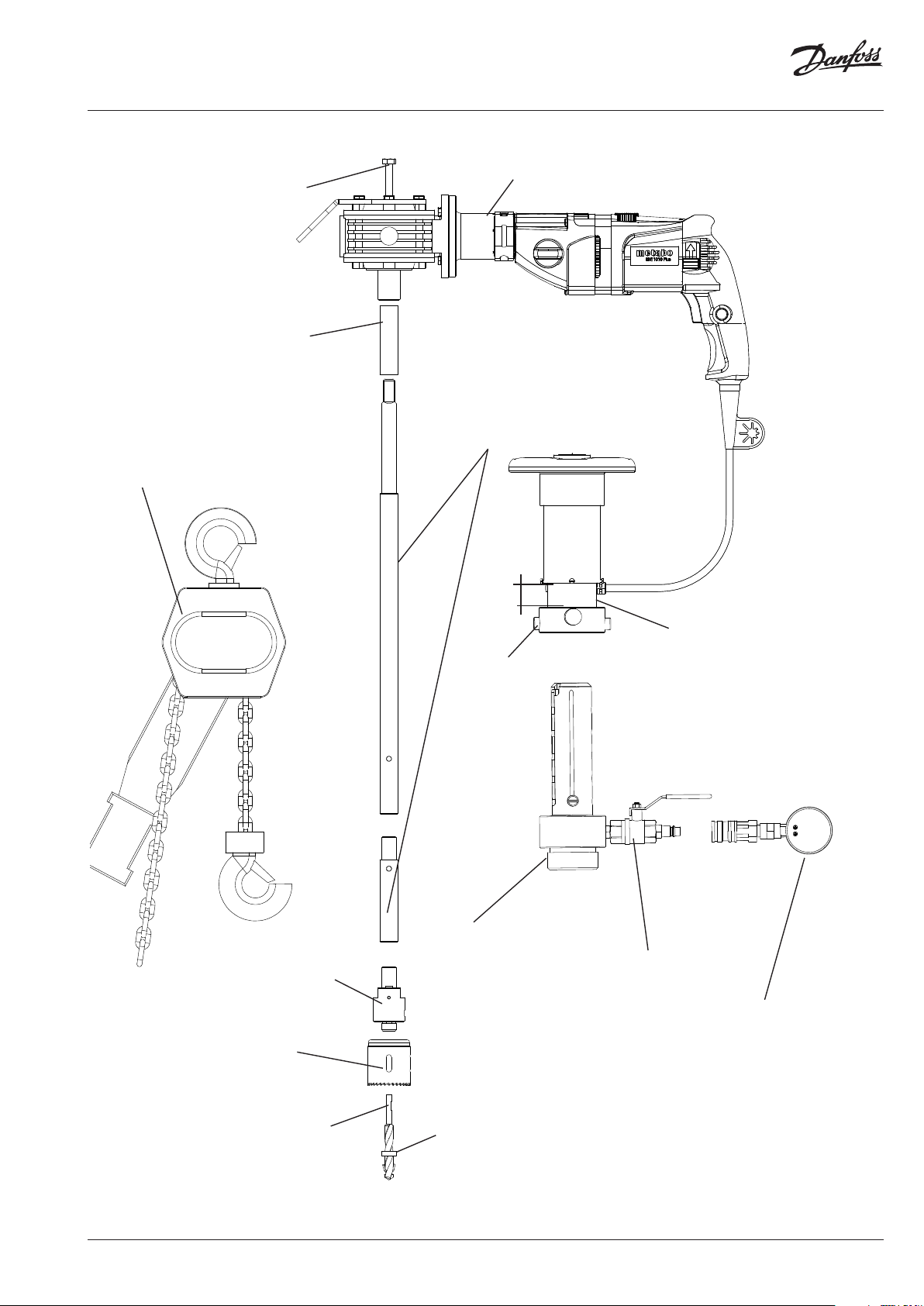
Gear Fastening Screw
Drive Unit (Drilling Machine +
Reduction Gearbox):
Rotates the drilling shaft.
Feed Extension Socket
Chain Block*
Recommended for
high pressures >12
bar for a safe relase of
the drilling shaft after
the drilling.
Drilling Shaft:
Transfers the torque from
the driving unit to the pilot
drill and hole saw.
The length can be adjusted
by shaft extensions.
Feed
Locking Screw:
Feed Unit:
Consists of adjusting socket and the
actual feed socket, which together
are used to adjust the starting
position for the drilling and while
machining create the movement
towards the main pipe.
Chuck:
A connection piece between
the rotating shaft and the
hole saw and pilot drill.
Hole Saw:
Creates the actual hole in the
pipeline
Pilot Drill:
Cuts rst and creates a center hole
for the hole saw. Allows the uid in
the mainline to enter the valve, the
device body and the adapters to cool
the hole saw. The wire inside catches
the coupon cut by the hole saw.
© Danfoss | 2022.03
Device Body:
A part containing
the sealings and
bearings.Contains
locking grooves to
adjust the starting
position of the
drilling
Control Cock:
Necessarry for
the pressure test
and the release of
pressure after the
drilling.
Magnet:
Can be used in ferromagnetic
pipe materials to catch most of
the drilling waste.
Pressure Gauge:
or carrying out
the pressure test.
Can be used as a
pressure monitoring
during the drilling
process
*Chain block on special request
AQ243486498056en-000302 | 7
Page 8
Operating Guide JIP Hot Tapping Machine Toolbox
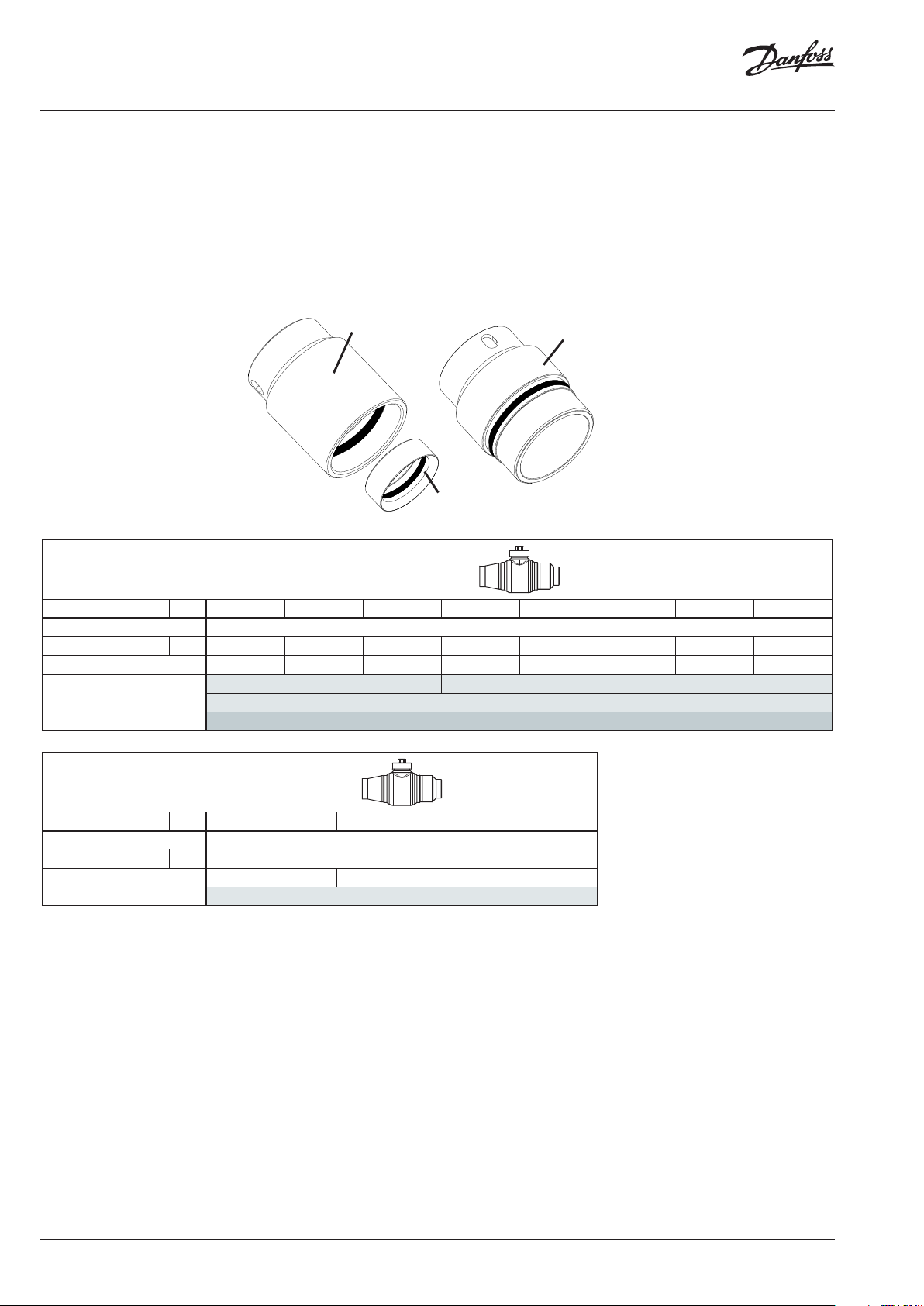
3.3 Danfoss JIP Hot Tap Valves for Hot tapping
The drilling device should be used to drill Danfoss JIP Hot Tap Ball Valves in a range from DN15 to DN100 and in
water-based heating and cooling systems. A connection between the machine body and the valve is realized by
threaded adapter pieces. Some adapter pieces are used for more than one nominal size by using adapter reduction
socket.
All adapters are designed to be used only for Danfoss JIP Hot Tap Valves. Keep in mind to control the allowed
pressure and temperature acc. chapter 3.1 and following Danfoss JIP Hot tap ball valves data sheet.
JIP Adapter <= DN50
JIP Adapter Socket
Standard valve versions
DN mm 15/20 25 32 40 50 65 80 100
PN 40 25
Hole saw diameter mm Ø15 Ø24 Ø24 Ø40 Ø40 Ø48 Ø65 Ø79
Code No. 065N0050 065N0051 065N0052 065N0053 065N0054 065N0055 065N0056 065N0057
06 5N1021 -
Tool box Code No.
06 5N1003 06 5N1004
JIP Adapter >= DN65
06 5N1002
OEM valve versions
DN mm 20 25 40
PN 40
Hole saw diameter mm Ø19 Ø32
Code No. 065N0070 065N0071 065N0072
Tool box Code No. 06 5N1022 065N1023
Depending on the valve length the shaft has to be adjusted. The recommended way to nd the correct shaft
lengths is shown in the pictures below.
- At rst, push the shaft forward so that the pilot drill touches the pipe surface.
- Measure the lengths between the lower shoulder of the shaft and the upper device body.
- The measured distance should be between 100 - 170 mm
- Adjust the length of the shaft if necessary as shown in chapter 4.2.1 and 4.2.2
8 | AQ243486498056en-000302
© Danfoss | 2022.03
Page 9

Operating Guide JIP Hot Tapping Machine Toolbox
The feeding distance is recommended to
be at least 35 mm.
100-170mm
> 40 mm
> 35mm
4. Operational Instructions
4.1 Branch Preparations before the Hot Tapping
Before the drilling process can start, the branch of the decided dimension has to be prepared. Keep in mind
that the branch size should be at least one nominal size smaller than the main line.
4.1.1 Removing the insulation
- If the main line is insulated, remove the insulation and
clean the pipe surface.
- Remove the insulation far enough in order to have
sufcient space for the welding.
4.1.2 Adjusting the Hot Tap Valve
Thread End
- Adjust the lower end of Danfoss Hot Tap Valve to the round
of the main line using a grinding machine.
- It is important that the valve is handled in a proper way to
prevent grind or other foreign particles to get into to valve.
It is suggested that you insert a rag to prevent damage of
internal parts. Before welding, the rag must be removed.
- The valve has to be fully open during the adjustment.
© Danfoss | 2022.03
Lower end to be adjusted
AQ243486498056en-000302 | 9
Page 10

Operating Guide JIP Hot Tapping Machine Toolbox
Picture 1
4.1.3 Welding of the Hot Tap Valve to the Main Line
- The hot tap valve can be welded on to the pipe
in every possible direction, but the angle between
the center line of the main pipe and the valve axis
must be 90°. The valve has to be welded by certied
welder. Welding technology electric arc welding or
TIG welding, with low current as possible. Ensure
surface along joint line is free of oxides and
grease.
Make sure that no welding material enters the valve.
Valve need to be welded to the main pipe by single
run closed fillet weld. Avoid multiple run fillet
welding to prevent overheating and potential
weld cracks.
The ideal relation between the weld throat thickness
and wall thickness of both welding parts need to be
considered (see picture 1).
- Before welding, check the closing mechanism of the
valve.
- During welding the ball valve must be open.
90°
d
- The valve has to be welded on by electric arc
welding.
- Make sure that no particles are entering the valve.
WARNING: Avoid multiple run llet welding
to prevent overheating
4.1.4 Testing the Valve
- Before starting the drilling process it is
mandatory to test the closing mechanism of
the valve.
- Use the proper key to close the valve and
open it completely afterwards
a= 0,7 x d*
d
Throat thickness (a)
* Considered welded part with the smaller wall thickness
(main pipe thickness or valve welding end thickness)
WARNING: NEVER start drilling if the
valve doesn't close or
open completely
10 | AQ243486498056en-000302
© Danfoss | 2022.03
Page 11

Operating Guide JIP Hot Tapping Machine Toolbox
4.2 Assembly of the Drilling Device
Danfoss Hot tapping machine is delivered in a box, including all the items described in chapter 3.2 plus
additional tools for (dis)assembly and pressure tests.
4.2.1 Assembly of the Shaft for hole saws > 32mm
- A proper hole saw ③ for the dimension
according to chapter 3.3 shall be chosen.
- It shall be connected winding clockwise to
the drill chuck ④.
- When connected, it shall be released
so much that the closest turning pins
E can be pushed through the holes F
at the bottom of the hole saw.
- The drill chip magnet ② can be put
around the pilot drill ① the drill is pushed to
the hole of the chuck aligning the groove B
and the screw A.
- Finally, the drill is locked by tightening the
screw A.
- The drill chuck shall be connected on
the top of the drilling shaft ⑤ or, if used, the
shaft extension ⑦.
B
①
②
③
A
E
④
F
⑥
- If the valve should be so long that the shaft
length would not be long enough to enable
the drilling, the useable shaft length can be
extended by the feed extension socket ⑥
at the end ot the shaft or by adding shaft
extensions ⑦ at lower end of the drilling
shaft ⑤.
CAUTION: Make sure that the
drilling shaft is screwed in
completely so that chuck
pins ⑧ are alining with the
chuck bottom.
NOTICE: Check that the pilot drill is neither too
big no too small for the used hole saw.
A too long pilot drill increases the
feeding distance unnecessarily while a
too short drill doesn't provide the
guidance for the hole saw.
© Danfoss | 2022.03
⑤
⑧
⑦
A
CAUTION: If the pilot drill it too long
it might be impossible to
close the valve !
AQ243486498056en-000302 | 11
Page 12

Operating Guide JIP Hot Tapping Machine Toolbox
4.2.2 Assembly of the shaft for hole saws < 32 mm
- For hole saws <32mm and >24mm use
the small chuck ⑧. The smallest chuck ⑨
should be used for hole saws <20mm.
- Screw the hole saw ③ to the chuck ⑧ or
⑨ depending on the hole saw size.
⑥
- The magnet ② has to be put around the
pilot drill ① and pushed into the hole of the
chuck ⑧ or ⑨.
- The groove in the pilot drill ① has to be
alligned to the screw G.
- Attach the assembly to the shaft ⑤. Use
shaft extensions ⑦ or the feed extension
socket ⑥ if necessary.
②
⑦
③
⑤
⑧
⑨
G
①
CAUTION: If the pilot drill it too long
it might be impossible to
close the valve !
4.2.3 Assembly of the Danfoss JIP Adapter Socket
The Danfoss JIP Hot Tapping Adapters are delivered in a tool box including all the sizes from DN 15/20 to DN 100.
For the sizes DN 25 as well as for DN40 reduction sockets have to be added to adapter of the next size as shown
in the following picture.
12 | AQ243486498056en-000302
© Danfoss | 2022.03
Page 13

Operating Guide JIP Hot Tapping Machine Toolbox
4.2.4 Assembly of the Device to the Hot Tapping Valve
- The adapter has to be connected to the thread of the valve by
rst winding with hand and tightening it tenderly using the wrench.
Because the tightening O-ring, it is not necessary to use much force
while connecting the parts.
- Prior connecting the adapter to the valve, a proper central drill,
hole saw, chuck and drill shaft have to be assembled together as
shown in chapter 4.2.1- 4.2.2.
- When all parts have been screwed on, test that it is still possible
close the valve as shown in the picture below ! Dismantle the
machine and adjust it again if the valve cannot be closed !
- Remember to FULLY open the valve after that !
4.2.5 Installing the Feed Unit
- The feed device ⑦ is used to create a feed force for the drillling.
- The feed thread has to be winded to back position completely by
turning the feed wheel ⑧ counter-clockwise.
- The adjusting socket ⑨ shall be connected by rst alignig the grooves
and the guide screws A and there after slided to the closest locking
groove B at the machine body.
- The excessive clearance is removed by turning the feed wheel ⑧
clockwise.
- Measure the feed distance as described in chapter 3.3 and adjust it by
shaft or feed extensions if possible.
B
A
⑧
⑦
⑨
© Danfoss | 2022.03
AQ243486498056en-000302 | 13
Page 14

Operating Guide JIP Hot Tapping Machine Toolbox
4.2.6 Installing the Driving Unit
- The shaft square shall be aligned with the
drive square hole and then connected and
locked using the connecting screw.
- The right rotating speed is chosen for the
drilling according the table below.
- For the pilot drill the maximum rpm is
suitable.
- An arrow on the left side of the machine
pointing upwards indicates the proper
clockwise rotating direction.
Warning: The drive must never run
counter clockwise since the drill shaft
connecting thread may open and the drill chuck
can be lost causing a severe hazard of hot
water leaking from the shaft opening.
Turning Speeds for Drilling in Steel Pipes
Metabo BE 1100 drilling machine settings shown in the table below. Recommended turning speeds based on the
manufacturers long term experience.
At the beginning of the drilling operation and at the end of drilling operation the cutting forces may vary highly so
one must be prepared to change the settings.
Valve size
Turning speed
drilling shaft [rpm]
Turning speed
electric drive [rpm]
Setting
Setting
DN 15 / 20 115 1600 9 1
DN 32 / 25 80 110 0 9 1
DN 50/40 80 110 0 9 1
DN 65 55 750 8 1
DN 80 55 750 8 1
DN 100 55 750 8 1
Pilot Drill 200 2800 9 2
14 | AQ243486498056en-000302
© Danfoss | 2022.03
Page 15

Operating Guide JIP Hot Tapping Machine Toolbox
4.3 The Hot Tapping Process
After the machine is assembled, all the connections shall be checked and controlled. The user can continue
with the following steps after that.
4.3.1 Pressure Test
Prior the actual branching a pressure test must be conducted to ensure the tightness of both the welding
seams of the valve and the drilling equipment.
- A hose ① of cold water or pressurized air is connected
to the coupler of the body.
- The control cock ② is opened to let the pressure in.
- If desired, close the control cock ② and mount the
pressure gauge ③ in order to monitor a possible fall of
pressure
- After the test, the test uid is released through the
same control cock ②
- In case of an occuring leakage, it is not allowed
to start the drilling process until the failure is
eliminated
③
②
①
© Danfoss | 2022.03
AQ243486498056en-000302 | 15
Page 16

Operating Guide JIP Hot Tapping Machine Toolbox
4.3.2 Starting the Driling Process
The drilling process starts by creating a center hole with the
pilot drill :
- The maximum rpm is chosen from switches and .
-The feed is started lightly by very slowly turning the feed
wheel clockwise.
- Feed very slowly in the beginning to ensure a good
centering of the central drill.
- A penetration of the pilot drill through the main pipe wall
can be observed by observing the pressure meter ⑦.
Raising of the needle indicates the penetration.
- An adequate feed using the max. rpm must be continued
until the pilot drill gets through the wall of the main line.
- After the pilot drill is through, the turning speed for the
hole saw has to be adjusted as described in chapter 4.2.6
- Start the feeding with the hole saw carefully and keep
a xed stand. Extra caution must be pointed to cope the
reaction forces. Pull the machine in the direction shown in
the picture to compensate the force.
- When the drilling advances, the feed rate can be slightly
accelerated until at the end of the drilling.
-The nal penetration of the main pipe wall can be
conrmed by pushing the shaft forward rmly without
turning shaft - When it advances, the hole must be free.
CAUTION: The drive must never be locked to
continuous run, since the variations of
machining forces may cause an unexpected
lost of control of the drive and thus cause
severe damage to the operator. Be aware
of the reaction forces from the cutting.
WARNING: The drive and the shaft must always turn
CLOCKWISE. Accidental opening of the
connecting threads of the shaft may cause
severe damage to the operator.
⑦
WARNING: NEVER use lever tools at the feeding wheel
and feed very carefully ! When the hole
saw gets stucked, stop feeding or turn the
saw a little bit backwards. Continue
feeding slowly !
16 | AQ243486498056en-000302
© Danfoss | 2022.03
Page 17

Operating Guide JIP Hot Tapping Machine Toolbox
4.3.3. Adjusting the Feed
①
- If the feed extent runs out and feed wheel ① can
not be turned anymore, the adjusting socket ②
must be released and locked to a lower groove.
- If the pressure is >12 bar, use the chain block
for this operation! The use of the chain block is
explained in chapter 4.6.
②
- At rst, switch of the driving unit.
- Screw the feed wheel ① counter clockwise.
- Don't unscrew it too much as the hook of the pilot
drill might break.
- Grip the adjusting handles ③ and push them
rmly forward.Turn the adjusting socket ② until it
can be released.
- Push the adjusting socket down in the direction of
the next groove.
- Continue to turn the feed wheel ① counter
clockwise until the next groove can be reached.
③
B
B
- Lock the adjusting socket ② to the next groove
by turning it clockwise.
Warning: If you are unsure about the forces
acting on the shaft while releasing it, use the chain
block for this operation. From the manufacturers
experience, it is advisable to use it at a pressure
>12 bar. See chapter 4.6 how to use the chain
block.
© Danfoss | 2022.03
AQ243486498056en-000302 | 17
Page 18

Operating Guide JIP Hot Tapping Machine Toolbox
4.3.4 Releasing the Feed Unit
After nishing the drilling, the drive shall be released from top of the assembly. In lower pressures, this
can be done by hand. For higher pressures >12 bar it is highly recommended to use the chain block.
- Both of the the adjusting handles ③ shall be gripped, pushed
forward and simultaniously turned counterclockwise to release the adusting socket.
- The socket can now be reversed by sliding the power screws
completely off from the drill body
- Release the shaft completely. The chuck inside the drilling
chamber stopps the shaft from comming out.
Warning: If you are unsure about the forces acting on the
shaft while releasing it, use the chain block for this operation.
From the manufacturers experience, it is advisable to use it at a
pressure >12 bar. See chapter 4.6 how to use the chain block.
4.3.5 Closing the Valve and Releasing the Pressure
- The valve has to be closed completely by turning the
ball using proper allen key and turning it 90 degrees.
Since the ball in the hot tap valve has no automatic
stop, you may have to adjust the position
of the ball until it is in correctly closed position.
- The tightness can be controlled by opening the
control cock.
③
- Connect the hose to the control cock and open it to
release the pressure
CAUTION: Keep enough distance to the
hose while releasing the
pressure to protect yourself.
Make sure the valve is
completely closed !
18 | AQ243486498056en-000302
© Danfoss | 2022.03
Page 19

Operating Guide JIP Hot Tapping Machine Toolbox
4.3.6 Disasembling of the Machine
The machine is dissasembled in the oposite order as shown in chapter 4.2. At the end, the cut out piece
shall be removed.
- The pilot drill is loosened by opening the retainer
screw using the proper allen key
- The central drill is pulled out and the coupon is
removed around the drill stem.
- The drill chips are cleaned from the gathering magnet
4.4 Creating the New Branch
For creating the new branch, follow the valve
manufacturers instructions carefully.
- When the Hot Tapping has been acomplished, the
new line can be connected to the Danfoss hot tap
valve by electric arc welding.
- During that operation, make sure that the sealings
inside the valve are not overheating.
- After the welding and when the line is approved to
start operatiing, open the valve rst very slowly.
- Open the valve COMPLETELY afterwards.
- After the valve is completely open, screw the top
plug. It is recommended to weld the plug to the
valve neck by single run closed llet weld. Fill the gap
between top plug and valve neck completely.
Avoid multiple run llet welding to prevent overheating.
© Danfoss | 2022.03
AQ243486498056en-000302 | 19
Page 20

Operating Guide JIP Hot Tapping Machine Toolbox
4.5 Maintanance Plan and Spare Part List
Before and after every hot tapping, the whole device should be visually inspected and maintained. Don't
start the drilling work without inspecting the device before. Never start the drilling if any damages are
observed. If any technical problems occur don't hesitate to contact the manufacturer Danfoss.
The following parts have to be inspected regarding their condition before every drilling:
Central Drill Inspect the central drill regarding its ability to cut .Change the drill if necessary.
Sealings Clean the sealings and inspect them regarding damages. Change them if necessary. Lubricate
them with sealant before using the device.
Hole Saw Inspect the hole saw regarding its ability to cut .Change the hole saw if necessary.
Shaft Inspect the shaft concerning surface damages. Check the connection threads. Store the shaft
properly and avoid droping it.
Bearings Visual check the condition of inner bearing surface
Thread of the
feed wheel
Whole Device Clean the device after each use and inspect it regarding visual damages
Check that the feeding wheel is going smoothly.
In case that major damages of the device are observed, please contact the manufacturer Danfoss.
20 | AQ243486498056en-000302
© Danfoss | 2022.03
Page 21

Operating Guide JIP Hot Tapping Machine Toolbox
11
12
13
14
15
10
9
8
7
6 5 4
3
1
2
52
51
50
49
23
16
17
18
19
20
21
22
23
24
25
26
27
28
48
47
46
45
44
43
42
41
27
© Danfoss | 2022.03
30
31
40
39
38
3229
36
353433
37
AQ243486498056en-000302 | 21
Page 22

Operating Guide JIP Hot Tapping Machine Toolbox
Position Part
1 Electric motor
2 Feed extension socket
3 Binding ring 43 mm
4 Primary chock
5 Coupling
6 Coupling casing
7 Retaining ring
8 Gear fastening Screw
9 Connecting screw M6
10 Shaft brake connecting plate
11 Connecting screw M5
12 Worm gear 7:1
13 Secondary chock
14 Secondary shaft
15 Lip Sealing
16 Thrust Bearing
17 Feed Socket
18 Retainer Screw
19 Handle
20 Adjusting Socket
21 Power Screw
22 Ball Point Screw
23 Upper Bearing Retaining Ring
24 Upper Bearing Sealing
25 O-ring upper bearing
26 Upper PTFE-Bearring
27 Shaft Sealing
28 Body
29 Lower PTFE Bearing
30 Body Sealing
31 Lower Bearing Retaining Ring
32 Double Nipple
33 Control Cock
34 Quick Connector, male
35 Quick Connector, female
36 Socket 1/4”
37 Manometer 40 bar
38 Central Drill normal
39 Central Drill short
40 Shaft extension DN20
41 Chuck normal
42 Chuck small
43 Shaft extension 90 mm
44 Base shaft
45 Shaft extension 180 mm
46 Chain Block
47 TONISCO Special Wrench
48 Opening Pin
49 Allen Key 3 mm
50 Allen Key 4 mm
51 Allen Key 5 mm
52 Magnet
22 | AQ243486498056en-000302
© Danfoss | 2022.03
Page 23

Operating Guide JIP Hot Tapping Machine Toolbox
4.6 Using the Chain Block
For higher pressures >12 bar it is highly recommended
to use the chain block for adjusting the feed (see chapter
4.3.3) or for a safe release of the feed unit (see chapter
4.3.4).
- First, hang the upper end of the hook in the connection
plate ① . The other hook has to be mounted to a stable
element of at the workside e.g. around the main pipe.
- Adjust the switch to the middle position for a free
movement of the chain.
- Tighten the chain by rst pulling the other end of
the chain and after that by turning the wheel
clockwise.
①
- Adjust the switch to the UP position
- Push down the adjusting socket ③ by moving the
lever back and forward
- Before releasing the locking screw from the groove
in the adjusting socket ③, adjust the switch to the
down position if you want to release the feed unit.
- If you want to adjust the feed, leave the switch in
the up position.
- Turn the adjusting socket ③ counterclockwise to
relase the shaft or adjust the feed.
③
CAUTION: Be careful to not squeeze
your hand in the chain. Read
the instruction manual from
the chain block manufacturer.
WARNING: Do not change the switch
to the middle position when the
chain is under tension.
© Danfoss | 2022.03
AQ243486498056en-000302 | 23
Page 24

Attachments A1
Safety Instructions in Regards to the Electrical Driving Unit
- Warning: When using electric tools, basic safety precautions should always be followed to reduce the risk ofelectric shock, personal
injury and re, including the following:
- Reed all these instructions before operating the power tools. Save these safety instructions.
- Keep work area clean. Cluttered areas and benches invite injuries.
- Consider work area environment. Don't expose power tolls to rain. Don't use power tolls in damp or wet locations. Keep work area well
lit. Don't use power tools in presence of ammable liquids or gases.
- Protect yourself from electric shock. When working with electric power tools, avoid body contact with earthed parts ( e.g. Pipes,
radiators, hobs, refrigerators) If you use electrically conductive coolers or lubricants or if there are extreme conditions for use ( e.g.
A high degree of humidity , development or metal dust, etc.) When working with electric power tools, use the ( FI, DI, PRDC ) residual
current protection devices at any power outlet point.
- Keep children away. Do not let onlookers contact tool or power lead. All onlookers should be kept away from work area.
- Store idle power tool for the job. When not in use keep tools in dry place, either locker up or high up, out of the reach of children.
- Never force a power tool. It will do the job better and safer at the rate for which it was tended.
- Use the right power tools for the job. Don't force small power tools to do the job of a heavy duty tool. Don't use power tools for purpose
not intended. Don't for example , use a circular saw for cutting tree limbs or logs.
- Dress properly. Do not wear loose clothing or jewelry. They can be caught in moving parts. Rubber glover and non-skid footwear are
recommended when working outdoors. Wear protective hair covering to contain long hear.
- Wear safety goggles and a face mask or dust mask if work is dusty.Don't abuse lead. Never carry power tool by lead or yank lead to
disconnect tool from receptacle. Keep the lead away from heat, oil and sharp edges.
Secure work piece. Use clamps or a vice to hold work piece. It's safer than using your hand and it frees both hands to operate.
- Don't overreach. Keep proper footing and balance at all times.
Maintain tools with care. Keep tools sharp and clean for better and safer performance. Follow instructions for servicing changing tools.
Inspect power tools leads periodically and if damaged, have them repaired by an authorized service facility. Inspect extension leads
periodically and replace them if damaged. Keep handles dry, clean and free from oil and grease.
- Disconnect power tools, when not in use, before servicing and when adjusting accessories such as blades, bits and cutters.
-
Remove keys and spanners. Form habit of checking to see that keys and adjusting tools are removed from power tool before turning them on.
- Avoid unintentional starting. Don't carry plugged-in power tool with nger on switch trigger. Be sure switch is turned off when plugging in.
- Outdoor use extension leads. When power tools is used outdoors, use only extension lead intended for use outdoors and so marked.
- Stay alert. Watch what you are doing. Use common sense. Do not operate power tool when you are tired.
- Check power tool for damaged parts. Before further use of the power tool, a guard or other part that is damaged should be
carefullychecked to determine that it will operate properly and perform its intended function. Check for alignment of moving parts,
binding or moving parts, breakage of parts, mounting , and any other condition that may affect the power tool's operation.
- A guard or other part that is damaged should be properly repaired or replaced by an authorized service facility unless otherwise
indicated in the operating instructions.
- Have defective switches replaced by an authorized service facility. Do not use the power tool if the switch does not turn it on and off.
- Warning!. For your own safety, use only accessories and attachments which are described in the operating instructions or are provided
or recommended by the tool manufacturer. The use of tools other then those described in the operating instructions or in the catalog of
recommended tool inserts or accessories can result in a risk of personal injury.
- Have your power tool repaired by an authorized service facility. Repairs should be carried out only by an authorized service facility.
24 | AQ243486498056en-000302
© Danfoss | DCS-SGDPT/SI | 2022.03
 Loading...