

Operation instruction
JIP Hot Tap Equipment
Description
The equipment makes it possible to connect new
branches to the net while in operation within the
dimensions from DN 20 up to DN 100.
This hot tap equipment should only be used in
district heating systems. If another application is
requested, please contact the producer.
Preparations
Notice: Generally good visibility and secured
position is required on the place to drill and
tap. To avoid injuries please make use of
protective gloves, protective spectacles and
protective clothing.
*
Before every drilling the main tool has to be
inspected. Please make sure that the drill/
hole-saw is in such a condition that the
process can be carried through; otherwise the
drill/hole saw has to be sharpened or renewed.
* Defective sealing and gaskets are to be
renewed.
* All Screws, which hold the centre drill and
the hole saw, have to be tightened very hard
before every tapping process.
Important message
Please observe the German directive FW 432
from October 1998 (former: AGFW-directive
4.2.8 from June 1995). This directive contains:
“Betriebliche Mindestanforderungen an die
Erstellung eines Rohr-abzweiges an in Betrieb
befindlichen Fernwärme-leitungen” (min.
working instructions when connection branches
to district heating pipes in operation according
to the hot tap method).
DEN-SMT/SI
VI.KD.E1.02 © Danfoss 04/2014
1
Operation instruction JIP Hot Tap Equipment
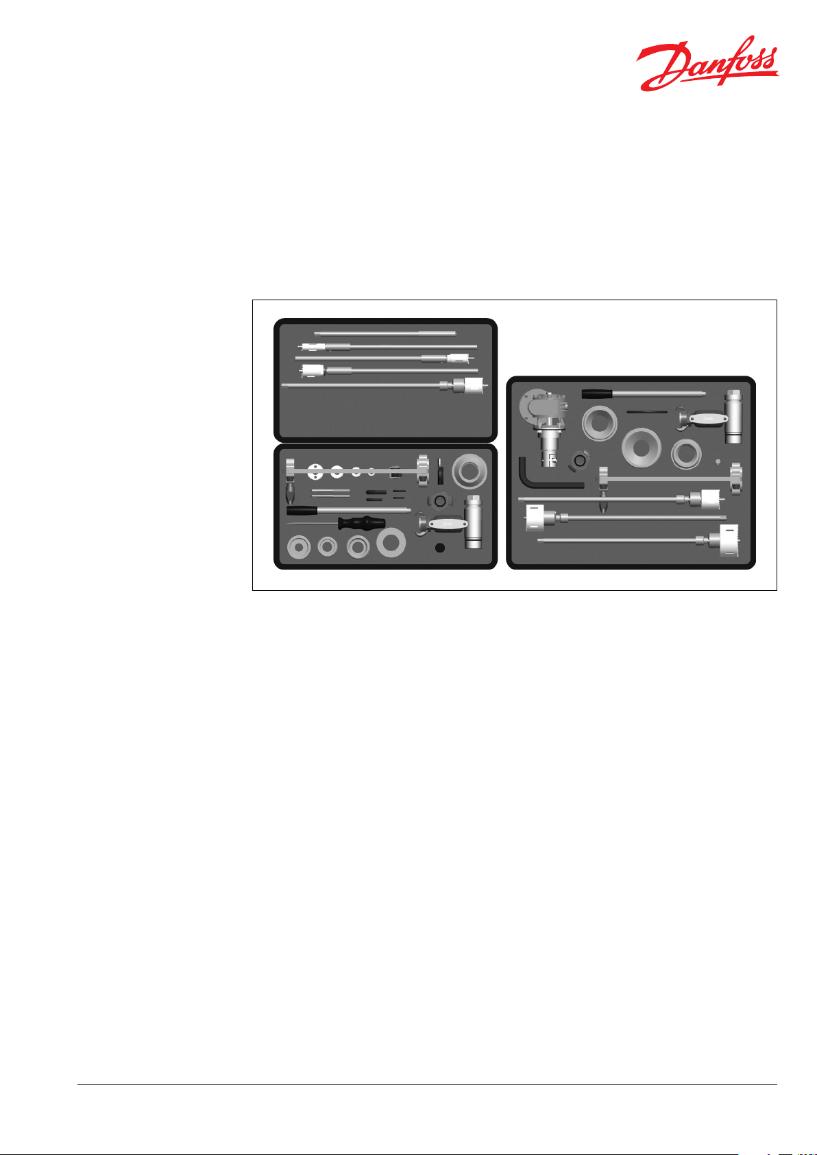
Design
1. 065N8006 - Drill Ø15
2. 065N7997 - Hole saw Ø19
3. 065N8008 - Hole saw Ø24
4. 065N7998 - Hole saw Ø32
5. 065N8010 - Hole saw Ø40
6. 20100098 - Center drill inst.
20100100 - Hot tapping inst.
20100101 - Table of contents
7. 065N8013 - Hole saw ø40
8. 065N8089 - Hole saw ø32
9. 065N8012 - Hole saw ø24
10. 065N8086 - Hole saw ø19
11. 065N8099 - Allen key set
12. 065N8101 - Service set
13. 065N8080 - Adapter ø26,9
14. 065N8087 - Adap. ø33,7-ø42,4
15. 065N8005 - Adap. ø48,3-ø60,3
16. 065N8084 - Adap. ø26,9-ø33,7
17. 065N8151 - Adap. ø48,3-ø60,3
18. 065N8103 - Feed tool
19. 065N8016 - Center drill 1/4"
20. 065N8241 - Allen key 10 mm
21. 065N8247 - Allen key 7 mm
22. 80100022 - Allen key 5 mm
23. 065N8248 - Allen key 4 mm
24. 065N7996 - Screw coupling
25. 065N8109 -
26. 065N8090 - Schrewdriver
27. 065N8130 - Hot tapping tool
28. 8010010 0 - Handle
Handle for feed tool
①
③
⑤
⑦ ⑧ ⑨ ⑩ ⑪
⑱
⑥
⑲
⑳
21
26
25
22
23
②
④
⑫
⑮
24
27
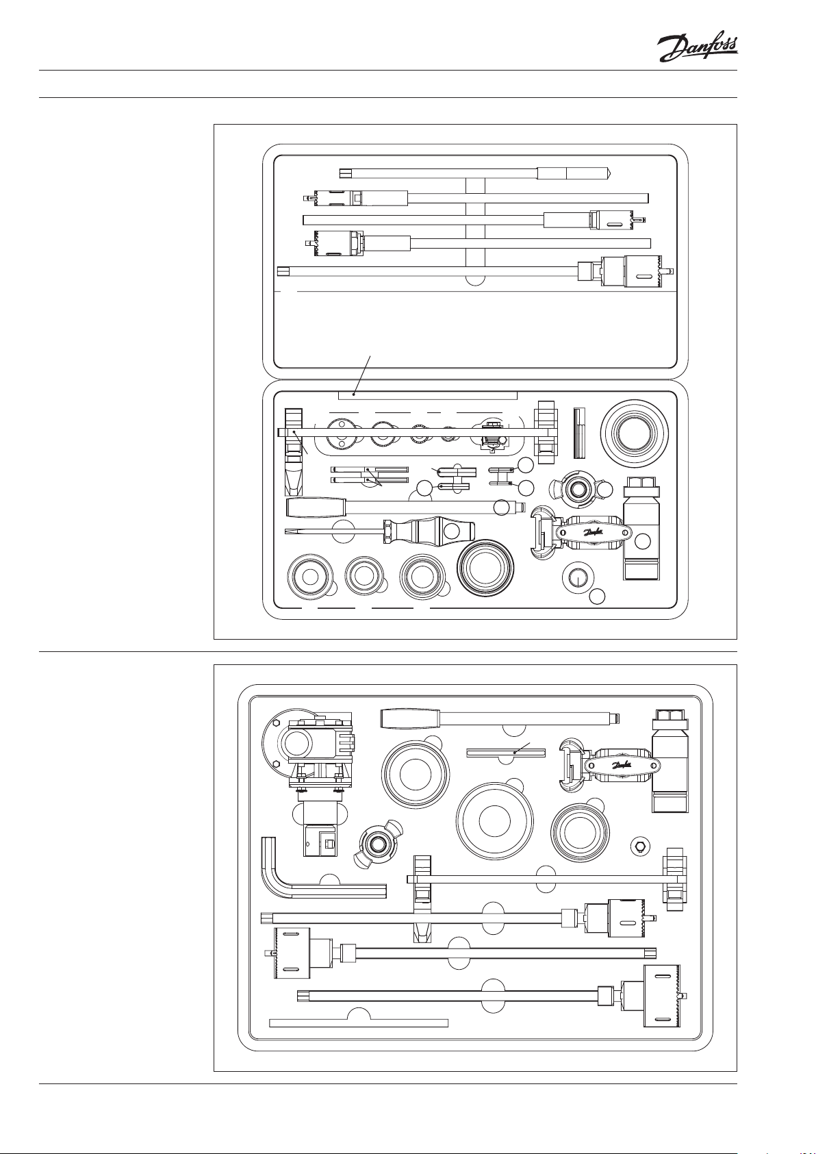
Design
1. 065N8102 - Reduction
wren ch 1:7
2. 065N8109 - Handle for feed
tool
3. 065N8130 - Hot tapping tool
4. 065N8112 - Service set
5. 065N8091 - Adapter ø76,1
6. 065N8094 - Adapter ø88,9
7. 065N8095 - Adapter ø114,3
8. 065N7995 - Stem for drilling
machine
9. 065N7996 - Screw coupling
10. 065N8242 - Allen key 14 mm
11. 065N8103 - Feed tool
12.
065N8172 - Hole saw ø48 comp.
13.
065N8192 - Hole saw ø65 comp.
14.
065N8193 - Hole saw ø79 comp.
15. 20100099 - Center drill inst.
20100100 - Hot tapping inst.
20100102 - Table of contents
⑬ ⑭
⑯
①
⑨
⑩
⑬
②
⑥
⑪
⑰
⑦
④
⑤
28
③
⑧
⑫
⑭
⑮
2
VI.KD.E1.02 © Danfoss 04/2014
DEN-SMT/SI
Operation instruction JIP Hot Tap Equipment
Removing the insulation
Note:
Remove the insulation and clean the
surface of the main pipe carefully.
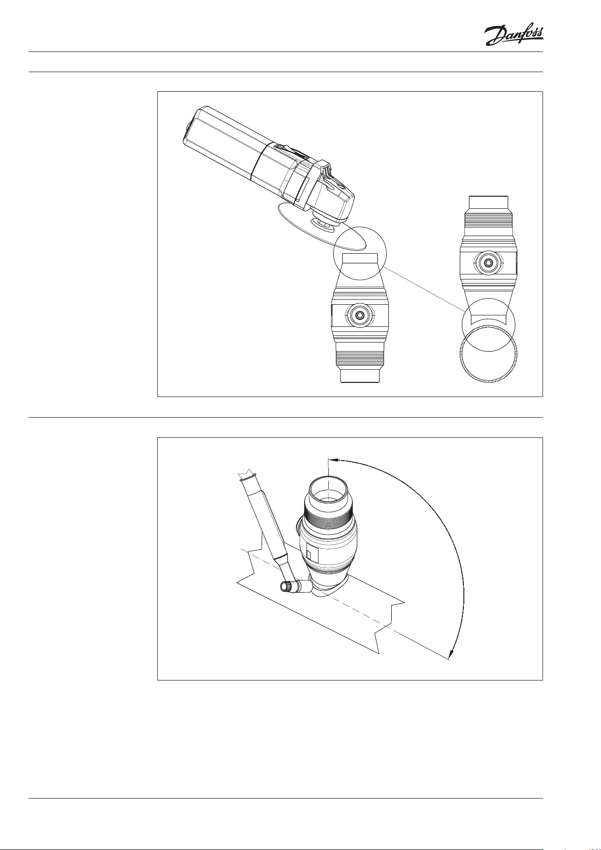
Adjust the hot tap valve
Note:
Before adjusting the hot tap valve
remove the conical lock screw ①
from hot tap valve, operate the
valve and set it back to fully open
position ③ using correct tools.
①
①
Conical
DN
lock screw
20 Allen Key 5 Flat screw driver 065N0106
25 Allen Key 7 All en Key 10 06 5N 0111
32 Allen Key 7 Allen Key 10 06 5N 0116
40 A llen Key 7 Alle n Key 10 065N 0121
50 Allen Key 7 Al len Key 10 065N0126
65 Allen Key 10 Allen Key 14 06 5N0131
80 Allen Key 10 Allen Key 14 0 65N0 136
100 Allen Key 10 Alle n Key 14 065N 0141
③
Valve
Operation
Valve
Code No.
③
②
DEN-SMT/SI
VI.KD.E1.02 © Danfoss 04/2014
3
Operation instruction JIP Hot Tap Equipment
Adjust the hot tap valve
continuous
Note:
It is important that the valve is
handled in a way to prevent grind
particles or other foreign particles
to get into the valve. The hot tap
valve MUST be in completely open
position.
Adjust the weld end of the hot
tap valve by means of a grinding
machine to the rounding of the
main pipe.
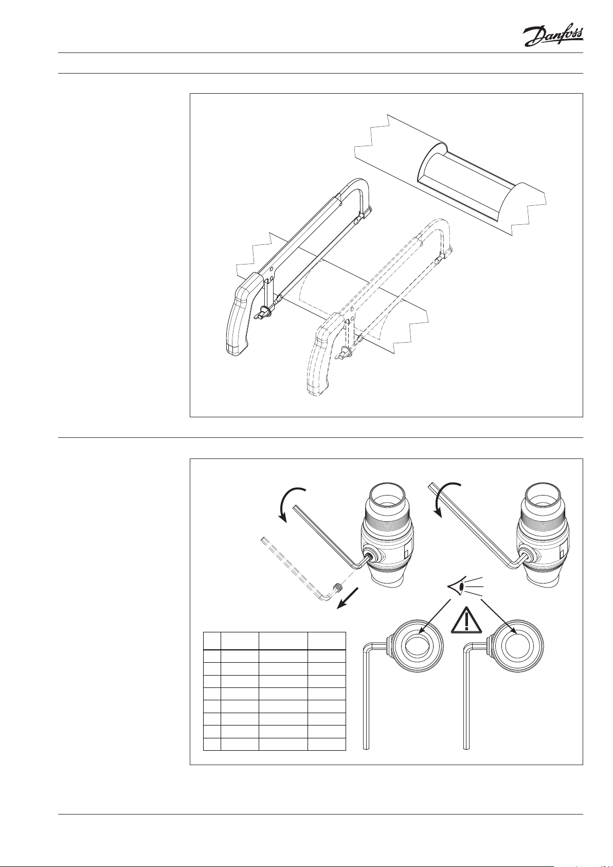
Welding of the hot tap valve
Note:
The hot tap valve can be welded on
to the pipe in whatever direction
you wish, but with an angle of
90° on center line of the main
pipe. During welding the hot tap
valve MUST be in completely open
position.
The valve has to be welded on by
electric arc welding. Since you are
going to drill through the valve, it is
very impor tant to make sure that no
welding material enters the valve.
90°
4
VI.KD.E1.02 © Danfoss 04/2014
DEN-SMT/SI

Operation instruction JIP Hot Tap Equipment
Tools mounting
Note:
Respective adapter and drill/holesaw should be selected according to
the valve size.
Mounting
Jip Hot tap Drill / Hole s aw Hole Ø Adapter
20 Drill Ø 15 mm Ø 26,9
25
Hole saw Ø 24 mm Ø 33,7 - Ø 42,4
32
40 Hole saw Ø 40 mm Ø 48,3 - Ø 6 0,3
Jip Hot tap Drill / Hole s aw Hole Ø Adapter
50 Hole saw Ø 40 mm Ø 48,3 - Ø 6 0,3
65 Hole saw Ø 48 mm Ø 76 ,1
80 Hole saw Ø 65 mm Ø 88 ,9
100 Hole saw Ø 79 mm Ø 114, 3
⑦
⑥
⑤
Note:
Adapter is mounted using special
handle following by hole-saw and
hot-tapping tool as shown on the
drawing above.
④
③
②
①
DEN-SMT/SI
VI.KD.E1.02 © Danfoss 04/2014
5

Operation instruction JIP Hot Tap Equipment
Installing feeding tool
⑤
②
≈0°
①
≈35°
③
Note:
To achieve a central pressure on the
drill equipment, it is recommended
to use the enclosed feeding tool.
④
⑥
⑦
6
VI.KD.E1.02 © Danfoss 04/2014
DEN-SMT/SI

Operation instruction JIP Hot Tap Equipment
Reduction wrench
①
Note:
For hot tap valves larger than DN
50 a reduction wrench is to be used.
This is also reccomended for the
smaller valves.
Mounting
④
③
②
⑤
Note:
Always operate with low speed and
without applying high pressure on
the drilling spindle.
Recommended maximum speeds
of the drilling are shown in the table
on the right.
DEN-SMT/SI
Hot-tap
valve size
100 120 rev/min
VI.KD.E1.02 © Danfoss 04/2014
Maxim um
drilling speed
(rev/min)
20
400 rev/min
25
32
40
250 rev/min
50
65 200 rev/min
Using reduction
wranch
Recommended
Obligatory80 150 rev/min
⑦
⑥
⑧
⑨
⑩
7

Operation instruction JIP Hot Tap Equipment
Installing Water hose
①
②
③
④
Note:
The outlet hose is to be connected
firmly with the coupling of the flush
valve. The free end of the hose has
to be placed far away from the place
of drilling and it has to be fastened
to avoid uncontrolled leak of hot
water.
⑦
⑥
⑤
⑧
8
VI.KD.E1.02 © Danfoss 04/2014
DEN-SMT/SI

Operation instruction JIP Hot Tap Equipment
The drilling process
Note:
Before starting the process of
drilling by means of the holesaw, it is to be checked that the
center drill of the hole-saw does
not prevent the ball from closing.
The drill equipment is pulled back
to stop-face and then the ball is
closed carefully. If the center drill is
projected too far into the passage
of the valve, then the tool has to be
dismounted and the center drill has
to be re-adjusted.
Note:
When started - point of no return
Don’t pull back again, you can
damage the barb, and loose the cut
out disc
Look out for reflex pulling back
when the center drill is through the
main pipe wall
Apply moderate pressure on the
feed tool
smaller drilling and sawing chips
less risk of loosing the disc
If hole saw gets stuck do not pull
back, reverse the drilling machine
Adapt flushing ball valve to the
situation
Avoid immerging the hole saw too
deeply into the water flow in the
main pipe.
When drilling large DN under high
pressure
Look out for forces on the drilling
shaft, pushing drilling machine,
feed tool and gear against yourself.
90°
③
②
①
DEN-SMT/SI
VI.KD.E1.02 © Danfoss 04/2014
9

Operation instruction JIP Hot Tap Equipment
The drilling process
continuous
32mm
Before and during drilling the packing box nut
on the main tool is to be tightened manually
to achieve optimal tightness, but at the same
time the drill equipment must be smoothrunning.
①
At the process of drilling it is important that
a necessary differential pressure is achieved
through optimal opening of the flush valve,
at that moment, when the circular blank has
been cut out. The pressure is necessary to
keep the cut away circular blank up in the
hole-saw. Therefore do not enter the drill
equipment further into the main pipe than
necessary.
③
Note:
When the drill /hole-saw is through the
wall of the main p ipe then pull the drill/
hole-saw ca refully all the way back to the
stop- face.
10
VI.KD.E1.02 © Danfoss 04/2014
②
DEN-SMT/SI

Operation instruction JIP Hot Tap Equipment
The drilling process
continuous
Note:
Turn the ball of the hot tap val ve 90° to
closed positio n by using a screwdriver/
Allen key. Make sure th at water does not
run from the hos e. Since the ball in the
hot tap valve has no auto matic stop, you
may have to adjus t the position of the
ball until it is in cor rectly closed position.
Remove the cut out piece
90°
Note:
Now the hot tap too l is to be dismounted
in opposite ord er and the cut out piece
should be rem oved.
Remove the cut out piece
Note:
Afterwa rds the valve can be opened
and the conical scre w mounted and
tightened. To get a ful ly welded pipe
system you must p lace a weld round the
conical screw.
DEN-SMT/SI
VI.KD.E1.02 © Danfoss 04/2014
11

Operation instruction JIP Hot Tap Equipment
The functioning of the
lock-screw
②
①
To illustrate the correct function of the conical lock-screw description is divided two scenarios (a
and b). Both scenarios are based on external demands to design and to the valves being installed in
underground district heating systems.
The design of the valve optimized for pre-insulated systems and insulation can be done without
unnecessary adaption and the requirements in EN 488 regarding fully welded district heating systems
are fulfilled.
Welding the conical lock-screw:
a) After welding in the valve, but before extending the pipe system
If the valve should function as an end valve for a longer period - before the pipeline is extended an end plate is welded on the free end of the valve. In this case the conical lock-screw is sealed with
a suitable sealing material (Teflon band) according to correct guidelines for good workmanship
and hereafter fastened with a common Allen key.
b) After extending the pipe system, but before insulating and covering the digging
When the work extending the pipe system has been finished and the valve is opened, the conical
lock-screw is dismounted, so that the valve can be turned into open position. Hereafter the conical
lock-screw is mounted again and fastened. Finally a welding seam is placed around the conical
lock-screw.
Attention - alternative 1!
It is important to pay attention to the fact that the simple O-ring situated at the stem of the valve
is not securing tightness on a longer view. The final and absolute tightness is reached by placing
the final welding seam around the lock-screw. Hereby you fulfill the requirements to a fully welded
system.
Attention - alternative 2!
If you, for some reason, do not want to fulfill the requirements for a fully welded system, you can
omit the welding seam. In this case the conical lock-screw is sealed with a suitable sealing material
(f.e. Teflon band) according to correct guidelines for good workmanship and hereafter fastened with
a common Allen key. Danfoss A/S consider this solution acceptable and the risk for untightens is
minimal. Danfoss A/S does however not grant any guarantee for tightness.
Insulation
When installation had been finalized insulation should be established.
12
VI.KD.E1.02 Produce d by Danfoss A/S © 0 4/2014
 Loading...