

Page 1
User Manual
PLUS+1® GUIDE Software
PLUS+1® Function Block Library—J1939
Function Blocks
www.danfoss.com
Page 2

User Manual
PLUS+1® Function Block Library—J1939 Function Blocks
Revision history Table of revisions
Date Changed Rev
September 2019 Rebranding. Added new function blocks. 0101
May 2016 —— EF
2 | © Danfoss | September 2019 11023438 | AQ310885477127en-000101
Page 3

User Manual
PLUS+1® Function Block Library—J1939 Function Blocks
Contents
Library Introduction
J1939.....................................................................................................................................................................................................9
Structure.............................................................................................................................................................................................. 9
Fault and Status Outputs...............................................................................................................................................................9
PGN Receivers
A1DEFI1_Rx—Aftertreatment 1 Diesel Exhaust Fluid Information 1 Receiver........................................................10
Inputs............................................................................................................................................................................................ 10
Outputs ....................................................................................................................................................................................... 10
A2DEFT1I1_Rx—Aftertreatment 2 Diesel Exhaust Fluid Tank 1 Information For Receiver.................................11
Inputs ........................................................................................................................................................................................... 11
Outputs ....................................................................................................................................................................................... 11
AAI_Rx—Auxiliary Analog Information Receiver............................................................................................................... 12
Inputs............................................................................................................................................................................................ 12
Outputs........................................................................................................................................................................................ 13
ACCS_Rx—Acceleration Sensor Receiver............................................................................................................................. 13
Inputs............................................................................................................................................................................................ 13
Outputs ....................................................................................................................................................................................... 14
AMB_Rx—Ambient Conditions Receiver.............................................................................................................................. 14
Inputs............................................................................................................................................................................................ 15
Outputs........................................................................................................................................................................................ 15
AT1S1_Rx—Aftertreatment 1 Service 1 Receiver...............................................................................................................15
Inputs ........................................................................................................................................................................................... 16
Outputs........................................................................................................................................................................................ 16
AT1S2_Rx—Aftertreatment 1 Service 2 Receiver...............................................................................................................17
Inputs............................................................................................................................................................................................ 17
Outputs........................................................................................................................................................................................ 17
AT2S_Rx—Aftertreatment 2 Service Receiver.....................................................................................................................18
Inputs............................................................................................................................................................................................ 18
Outputs........................................................................................................................................................................................ 18
AT1T1I_Rx—Aftertreatment 1 Diesel Exhaust Fluid Tank 1 Information Receiver................................................ 19
Inputs............................................................................................................................................................................................ 19
Outputs........................................................................................................................................................................................ 19
BJM_Rx—Basic Joystick Message Receiver.......................................................................................................................... 20
Inputs............................................................................................................................................................................................ 20
Outputs ....................................................................................................................................................................................... 21
BJM1_Rx—Basic Joystick Message 1 Receiver.................................................................................................................... 21
Inputs............................................................................................................................................................................................ 22
Outputs........................................................................................................................................................................................ 22
BJM2_Rx—Basic Joystick Message 2 Receiver.................................................................................................................... 23
Inputs............................................................................................................................................................................................ 24
Outputs........................................................................................................................................................................................ 24
CCVS1_Rx—Cruise Control/Vehicle Speed 1 Receiver.....................................................................................................25
Inputs............................................................................................................................................................................................ 26
Outputs........................................................................................................................................................................................ 26
CM1_Rx—Cab Message 1 Receiver.........................................................................................................................................28
Inputs............................................................................................................................................................................................ 28
Outputs........................................................................................................................................................................................ 29
DD_Rx—Dash Display Receiver................................................................................................................................................30
Inputs ........................................................................................................................................................................................... 31
Outputs........................................................................................................................................................................................ 31
DLCC1_Rx—Direct Lamp Control Command Receiver....................................................................................................31
Inputs............................................................................................................................................................................................ 32
Outputs ....................................................................................................................................................................................... 32
DPFC1_Rx—Diesel Particulate Filter Control 1 Receiver.................................................................................................34
Inputs............................................................................................................................................................................................ 34
Outputs........................................................................................................................................................................................ 34
EBC1_Rx—Electronic Brake Controller 1 Receiver.............................................................................................................37
Inputs............................................................................................................................................................................................ 37
Outputs........................................................................................................................................................................................ 37
©
Danfoss | September 2019 11023438 | AQ310885477127en-000101 | 3
Page 4

User Manual
PLUS+1® Function Block Library—J1939 Function Blocks
Contents
EEC1_Rx—Electronic Engine Controller 1 Receiver.......................................................................................................... 39
Inputs............................................................................................................................................................................................ 39
Outputs........................................................................................................................................................................................ 40
EEC2_Rx—Electronic Engine Controller 2 Receiver.......................................................................................................... 41
Inputs............................................................................................................................................................................................ 41
Outputs........................................................................................................................................................................................ 41
EEC3_Rx—Electronic Engine Controller 3 Receiver.......................................................................................................... 42
Inputs............................................................................................................................................................................................ 43
Outputs........................................................................................................................................................................................ 43
EFL_P1_Rx—Engine Fluid Level/Pressure 1 Receiver.......................................................................................................44
Inputs............................................................................................................................................................................................ 44
Outputs........................................................................................................................................................................................ 44
EFL_P2_Rx—Engine Fluid Level/Pressure 2 Receiver.......................................................................................................45
Inputs............................................................................................................................................................................................ 45
Outputs........................................................................................................................................................................................ 45
EJM_Rx—Extended Joystick Message Receiver..................................................................................................................46
Inputs............................................................................................................................................................................................ 46
Outputs........................................................................................................................................................................................ 47
EJM1_Rx—Extended Joystick Message 1 Receiver............................................................................................................47
Inputs............................................................................................................................................................................................ 48
Outputs........................................................................................................................................................................................ 48
EJM2_Rx—Extended Joystick Message 2 Receiver............................................................................................................49
Inputs............................................................................................................................................................................................ 49
Outputs........................................................................................................................................................................................ 49
EOI_Rx—Engine Operating Information Receiver.............................................................................................................50
Inputs ........................................................................................................................................................................................... 50
Outputs........................................................................................................................................................................................ 51
ERC1_Rx—Engine Retarder Control Receiver......................................................................................................................52
Inputs............................................................................................................................................................................................ 53
Outputs........................................................................................................................................................................................ 53
ET1_Rx—Engine Temperature 1 Receiver............................................................................................................................ 54
Inputs............................................................................................................................................................................................ 55
Outputs........................................................................................................................................................................................ 55
ET2_Rx—Engine Temperature 2 Receiver............................................................................................................................ 56
Inputs............................................................................................................................................................................................ 56
Outputs........................................................................................................................................................................................ 56
ET3_Rx—Engine Temperature 3 Receiver............................................................................................................................ 57
Inputs............................................................................................................................................................................................ 57
Outputs........................................................................................................................................................................................ 57
ETC1_Rx—Electronic Transmission Controller 1 Receiver..............................................................................................58
Inputs............................................................................................................................................................................................ 58
Outputs........................................................................................................................................................................................ 58
ETC2_Rx—Electronic Transmission Controller 2 Receiver..............................................................................................59
Inputs............................................................................................................................................................................................ 60
Outputs........................................................................................................................................................................................ 60
ETC5_Rx—Electronic Transmission Controller 5 Receiver..............................................................................................60
Inputs............................................................................................................................................................................................ 61
Outputs........................................................................................................................................................................................ 61
FD_Rx—Fan Drive Receiver........................................................................................................................................................62
Inputs............................................................................................................................................................................................ 62
Outputs........................................................................................................................................................................................ 62
HOURS_Rx—Engine Hours, Revolutions Receiver.............................................................................................................63
Inputs............................................................................................................................................................................................ 63
Outputs........................................................................................................................................................................................ 64
IC1_Rx—Intake/Exhaust Conditions 1 Receiver................................................................................................................. 64
Inputs............................................................................................................................................................................................ 64
Outputs........................................................................................................................................................................................ 65
IMT1_Rx—Intake Manifold Information 1 Receiver.......................................................................................................... 65
Inputs............................................................................................................................................................................................ 66
4 | © Danfoss | September 2019 11023438 | AQ310885477127en-000101
Page 5

User Manual
PLUS+1® Function Block Library—J1939 Function Blocks
Contents
Outputs........................................................................................................................................................................................ 66
LFC_Rx - Fuel Consumption (Liquid) Receiver.....................................................................................................................66
Inputs............................................................................................................................................................................................ 67
Outputs........................................................................................................................................................................................ 67
LFE_Rx—Fuel Economy (Liquid) Receiver............................................................................................................................ 67
Inputs............................................................................................................................................................................................ 68
Outputs........................................................................................................................................................................................ 68
LFI_Rx—Fuel Information (Liquid) Receiver.........................................................................................................................68
Inputs............................................................................................................................................................................................ 69
Outputs........................................................................................................................................................................................ 69
OI_Rx—Operator Indicators Receiver.....................................................................................................................................69
Inputs............................................................................................................................................................................................ 70
Outputs........................................................................................................................................................................................ 70
PGN_Rx—Parameter Group Number Receiver...................................................................................................................71
Inputs............................................................................................................................................................................................ 71
Outputs........................................................................................................................................................................................ 72
PGN_Mask_Rx—Parameter Group Number Mask Receiver...........................................................................................72
Inputs ........................................................................................................................................................................................... 72
Outputs........................................................................................................................................................................................ 73
SCRSC_Rx—Selective Catalytic Reduction System Cleaning Receiver.......................................................................73
Inputs............................................................................................................................................................................................ 74
Outputs........................................................................................................................................................................................ 74
SEP1_Rx—Sensor Electrical Power 1 Receiver.................................................................................................................... 76
Inputs............................................................................................................................................................................................ 76
Outputs ....................................................................................................................................................................................... 76
SHUTDN_Rx—Shutdown Receiver..........................................................................................................................................77
Inputs............................................................................................................................................................................................ 77
Outputs........................................................................................................................................................................................ 78
TCO1_Rx—Tachograph 1 Receiver......................................................................................................................................... 79
Inputs............................................................................................................................................................................................ 80
Outputs........................................................................................................................................................................................ 80
TD_Rx—Time/Date Receiver..................................................................................................................................................... 81
Inputs............................................................................................................................................................................................ 82
Outputs........................................................................................................................................................................................ 82
TRF1_Rx—Transmission Fluids 1 Receiver............................................................................................................................83
Inputs............................................................................................................................................................................................ 83
Outputs........................................................................................................................................................................................ 83
VD_Rx—Vehicle Distance Receiver......................................................................................................................................... 84
Inputs............................................................................................................................................................................................ 85
Outputs........................................................................................................................................................................................ 85
VDS_Rx—Vehicle Direction/Speed Receiver....................................................................................................................... 85
Inputs............................................................................................................................................................................................ 86
Outputs........................................................................................................................................................................................ 86
VEP1_Rx—Vehicle Electrical Power Receiver.......................................................................................................................86
Inputs............................................................................................................................................................................................ 87
Outputs........................................................................................................................................................................................ 87
VF_Rx—Vehicle Fluids Receiver................................................................................................................................................87
Inputs............................................................................................................................................................................................ 88
Outputs........................................................................................................................................................................................ 88
VP1_Rx—Vehicle Position Receiver 1.....................................................................................................................................88
Inputs ........................................................................................................................................................................................... 89
Outputs........................................................................................................................................................................................ 89
PGN Transmitters
ACK_Tx—Acknowledge Transmitter......................................................................................................................................90
Inputs............................................................................................................................................................................................ 90
Outputs........................................................................................................................................................................................ 91
AT1T1I_Tx—Aftertreatment 1 Diesel Exhaust Fluid Tank 1 Information Transmitter.......................................... 91
Inputs............................................................................................................................................................................................ 91
Outputs ....................................................................................................................................................................................... 92
©
Danfoss | September 2019 11023438 | AQ310885477127en-000101 | 5
Page 6

User Manual
PLUS+1® Function Block Library—J1939 Function Blocks
Contents
CCVS1_Tx—Cruise Control/Vehicle Speed 1 Transmitter...............................................................................................93
Inputs............................................................................................................................................................................................ 93
Outputs ....................................................................................................................................................................................... 96
CM1_Tx—Cab Message 1 Transmitter...................................................................................................................................96
Inputs............................................................................................................................................................................................ 96
Outputs ....................................................................................................................................................................................... 99
CM2_Tx—Cab Message 2 Transmitter...................................................................................................................................99
Inputs............................................................................................................................................................................................ 99
Outputs .....................................................................................................................................................................................101
DD_Tx—Dash Display Transmitter....................................................................................................................................... 101
Inputs..........................................................................................................................................................................................102
Outputs .....................................................................................................................................................................................103
DPFC1_Tx—Diesel Particulate Filter Control 1 Transmitter.........................................................................................103
Inputs..........................................................................................................................................................................................103
Outputs .....................................................................................................................................................................................107
EBC1_Tx—Electronic Brake Controller 1 Transmitter.....................................................................................................107
Inputs..........................................................................................................................................................................................107
Outputs .....................................................................................................................................................................................110
EEC1_Tx—Electronic Engine Controller 1 Transmitter..................................................................................................110
Inputs..........................................................................................................................................................................................110
Outputs......................................................................................................................................................................................112
ETC2_Tx—Electronic Transmission Controller 2 Transmitter......................................................................................112
Inputs..........................................................................................................................................................................................112
Outputs......................................................................................................................................................................................113
ETC5_Tx—Electronic Transmission Controller 5 Transmitter......................................................................................113
Inputs..........................................................................................................................................................................................113
Outputs......................................................................................................................................................................................114
OI_Tx—Operator Indicators Transmitter............................................................................................................................115
Inputs..........................................................................................................................................................................................115
Outputs......................................................................................................................................................................................116
PGN_Tx—Parameter Group Number Transmitter...........................................................................................................117
Inputs..........................................................................................................................................................................................117
Outputs .....................................................................................................................................................................................118
SHUTDN_Tx—Shutdown Transmitter................................................................................................................................. 118
Inputs..........................................................................................................................................................................................118
Outputs......................................................................................................................................................................................121
TRF2_Tx—Transmission Fluids 2 Transmitter...................................................................................................................121
Inputs..........................................................................................................................................................................................121
Outputs......................................................................................................................................................................................122
TSC1_Tx—Torque/Speed Control 1 Transmitter............................................................................................................. 123
Inputs..........................................................................................................................................................................................123
Outputs .....................................................................................................................................................................................124
VEP1_Tx—Vehicle Electrical Power 1 Transmitter...........................................................................................................125
Inputs .........................................................................................................................................................................................125
Outputs......................................................................................................................................................................................126
VF_Tx—Vehicle Fluids Transmitter.......................................................................................................................................126
Inputs..........................................................................................................................................................................................126
Outputs .....................................................................................................................................................................................127
PGN Requesters
Req_AAI_Tx—Request Auxiliary Analog Information Transmitter........................................................................... 128
Inputs..........................................................................................................................................................................................128
Outputs......................................................................................................................................................................................128
Req_DM2_Tx—Request Diagnostic Message 2 Transmitter.......................................................................................129
Inputs..........................................................................................................................................................................................129
Outputs......................................................................................................................................................................................129
Req_HOURS_Tx—Request Engine Hours, Revolutions Transmitter.........................................................................130
Inputs..........................................................................................................................................................................................130
Outputs .....................................................................................................................................................................................130
Req_LFC_Tx—Request Fuel Consumption (Liquid) Transmitter............................................................................... 131
6 | © Danfoss | September 2019 11023438 | AQ310885477127en-000101
Page 7

User Manual
PLUS+1® Function Block Library—J1939 Function Blocks
Contents
Inputs .........................................................................................................................................................................................131
Outputs .....................................................................................................................................................................................131
Req_LFI_Tx—Request Fuel Information (Liquid) Transmitter.....................................................................................132
Inputs .........................................................................................................................................................................................132
Outputs .....................................................................................................................................................................................132
Req_NAMES_Tx—Request NAMES Transmitter...............................................................................................................133
Inputs .........................................................................................................................................................................................133
Outputs......................................................................................................................................................................................133
Req_PGN_Rx—Request PGN Receiver................................................................................................................................ 134
Inputs..........................................................................................................................................................................................134
Outputs......................................................................................................................................................................................134
Req_PGN_Tx—Request PGN Transmitter.......................................................................................................................... 135
Inputs..........................................................................................................................................................................................135
Outputs .....................................................................................................................................................................................135
Req_VDS_Tx—Request Vehicle Direction/Speed Transmitter................................................................................... 136
Inputs..........................................................................................................................................................................................136
Outputs......................................................................................................................................................................................136
Req_VEP_Tx—Request Vehicle Electrical Power Transmitter.....................................................................................137
Inputs..........................................................................................................................................................................................137
Outputs .....................................................................................................................................................................................137
Bi-Directional Transmitters and Receivers
Addr_Claim_Tx_Rx—Address Claim Transmitter and Receiver.................................................................................138
Inputs..........................................................................................................................................................................................138
Outputs......................................................................................................................................................................................139
NACK_Tx_Rx—Negative Acknowledge Transmitter......................................................................................................139
Inputs..........................................................................................................................................................................................139
Outputs......................................................................................................................................................................................140
Names_Rx—Names Receiver..................................................................................................................................................140
Inputs..........................................................................................................................................................................................140
Outputs......................................................................................................................................................................................141
PMI_Tx_Rx—Proprietary Method Transmitter and Receiver.......................................................................................142
Inputs..........................................................................................................................................................................................142
Outputs......................................................................................................................................................................................142
TransProtocol_Rx.........................................................................................................................................................................143
TP_BAM_Rx—Transport Protocol BAM Receiver........................................................................................................143
Inputs.................................................................................................................................................................................... 143
Outputs.................................................................................................................................................................................143
TP_RTS_CTS_Rx—Transport Protocol RTS CTS Receiver.........................................................................................144
Inputs.................................................................................................................................................................................... 144
Outputs.................................................................................................................................................................................144
Select_TP_Msg—Select Transport Protocol Message..............................................................................................146
Inputs.................................................................................................................................................................................... 146
Store_TP_Msg—Store Transport Protocol Message.................................................................................................146
Inputs.................................................................................................................................................................................... 147
Parsers........................................................................................................................................................................................ 147
CA_Parser—Command Address Parser....................................................................................................................147
CI_Parser—Component Identification Parser........................................................................................................148
DM04_Parser—Diagnostic Message 4 Parser........................................................................................................ 149
DTC_Parser—Diagnostic Trouble Code Parser......................................................................................................150
EC1_Parser—Engine Configuration 1 Parser..........................................................................................................152
VIN_Parser—Vehicle Identification Number Parser.............................................................................................155
TransProtocol_Tx—Transportation Protocol Transmitter............................................................................................156
Inputs..........................................................................................................................................................................................156
Outputs......................................................................................................................................................................................157
Diagnostic Function Blocks
DM1_Rx—Diagnostic Message 1 Receiver.........................................................................................................................158
Inputs..........................................................................................................................................................................................158
Outputs......................................................................................................................................................................................159
©
Danfoss | September 2019 11023438 | AQ310885477127en-000101 | 7
Page 8

User Manual
PLUS+1® Function Block Library—J1939 Function Blocks
Contents
DM2_Rx—Diagnostic Message 2 Receiver.........................................................................................................................160
Inputs..........................................................................................................................................................................................161
Outputs......................................................................................................................................................................................162
DM1_DM2_Tx_Rx—Diagnostic Message 1 and 2 Transmitter...................................................................................163
Inputs..........................................................................................................................................................................................164
Outputs......................................................................................................................................................................................165
DM3_Rx—Diagnostic Message 3 Receiver.........................................................................................................................165
Inputs..........................................................................................................................................................................................165
Outputs......................................................................................................................................................................................165
DM1_Tx—Diagnostic Message 1 Transmitter...................................................................................................................166
Inputs..........................................................................................................................................................................................166
Outputs......................................................................................................................................................................................167
DM2_Tx—Diagnostic Message 2 Transmitter...................................................................................................................168
Inputs..........................................................................................................................................................................................168
Outputs......................................................................................................................................................................................169
DM3_Tx—Diagnostic Message 3 Transmitter...................................................................................................................170
Inputs..........................................................................................................................................................................................170
Outputs......................................................................................................................................................................................170
DM13_Rx—Diagnostic Message 13 Receiver....................................................................................................................170
Inputs..........................................................................................................................................................................................171
Outputs......................................................................................................................................................................................171
8 | © Danfoss | September 2019 11023438 | AQ310885477127en-000101
Page 9
User Manual
PLUS+1® Function Block Library—J1939 Function Blocks
Library Introduction
The SAE J1939 protocol is a vehicle communications bus standard designed for use in the off highway
and heavy truck markets.
J1939
Standards documents can be obtained through SAE International.
Structure
The function blocks in this library are organized into several types:
•
PGN Receivers – Designed to receive J1939 application data that is broadcasted onto the CAN bus.
Reference information can be found in SAE J1939-DA.
•
PGN Transmitters – Designed to transmit J1939 application data onto the CAN bus. Reference
information can be found in SAE J1939-DA.
•
PGN Requesters – Designed to transmit requests for J1939 application data. Reference information
can be found in SAE J1939-21.
•
Network Management – Designed to manage the various devices on the network. Typical tasks
include claiming a network source address and tracking the source address of other devices.
Reference information can be found in SAE J1939-81.
•
Diagnostics – Designed to support the various diagnostic needs of the system. Reference information
can be found in SAE J1939-73.
Fault and Status Outputs
Not all messages defined by J1939 are implemented in the library. This collection contains some of the
more commonly used messages in the off highway and heavy truck industries.
An application can use the AddrClaim_Tx_Rx function block to determine its J1939 address. The
Address and Claimed output of this block can be used to drive enable and address inputs for the
transmitting blocks in the library.
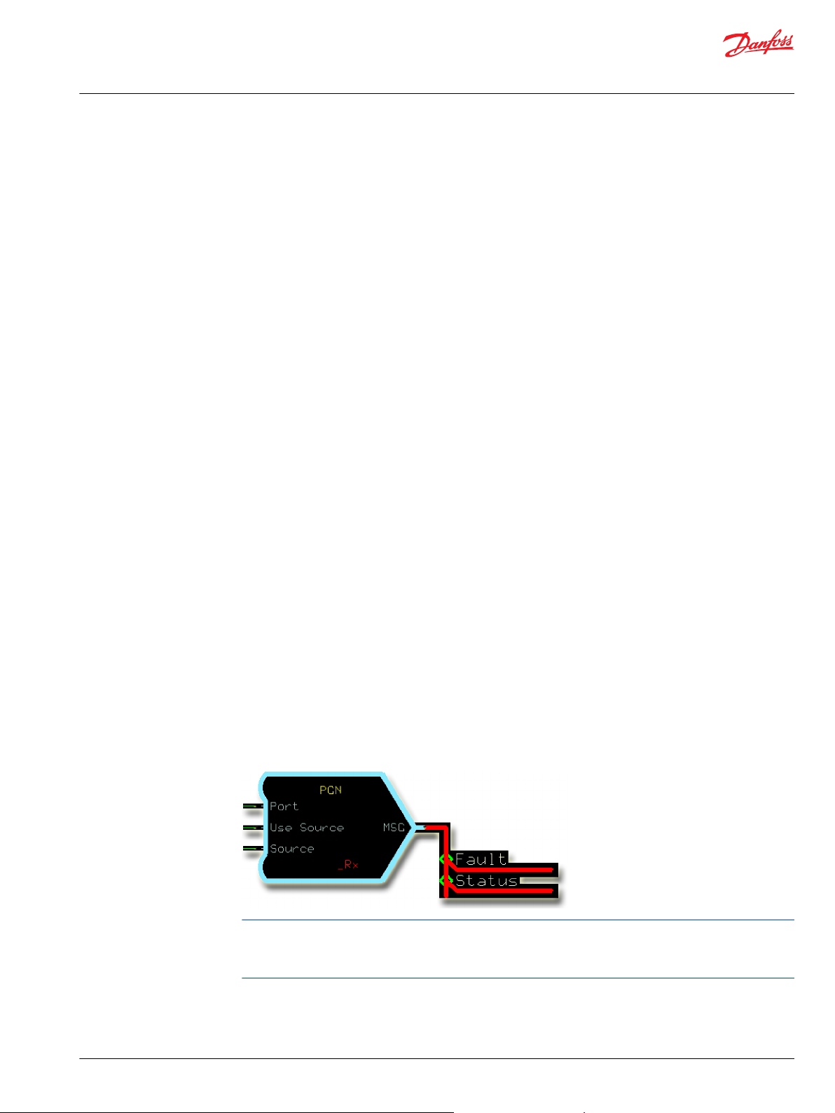
For most PGN receive function blocks, there are two sub-busses within the MSG output data bus.
The Fault bus contains a duplicate set of signals of the MSG bus, but appended with _Flt. If there is an
error indicated for a particular signal, the corresponding _Flt signal is true. This error code is sent in place
of the actual data and is not related to receiving DM1 data. This signal is true no matter which specific
error code is sent.
The Status bus contains a duplicate set of signals of the MSG bus, but appended with _NA. If data is not
available for a particular signal, the corresponding _NA signal is true.
Not all signals have _Flt or _NA counterparts. This occurs when the standard does not define this
information for a signal. In some cases, the error information defined is complex and is better handled in
a different way.
©
Danfoss | September 2019 11023438 | AQ310885477127en-000101 | 9
Page 10
User Manual
PLUS+1® Function Block Library—J1939 Function Blocks
PGN Receivers
PGN receivers receive J1939 data broadcast on the CAN bus.
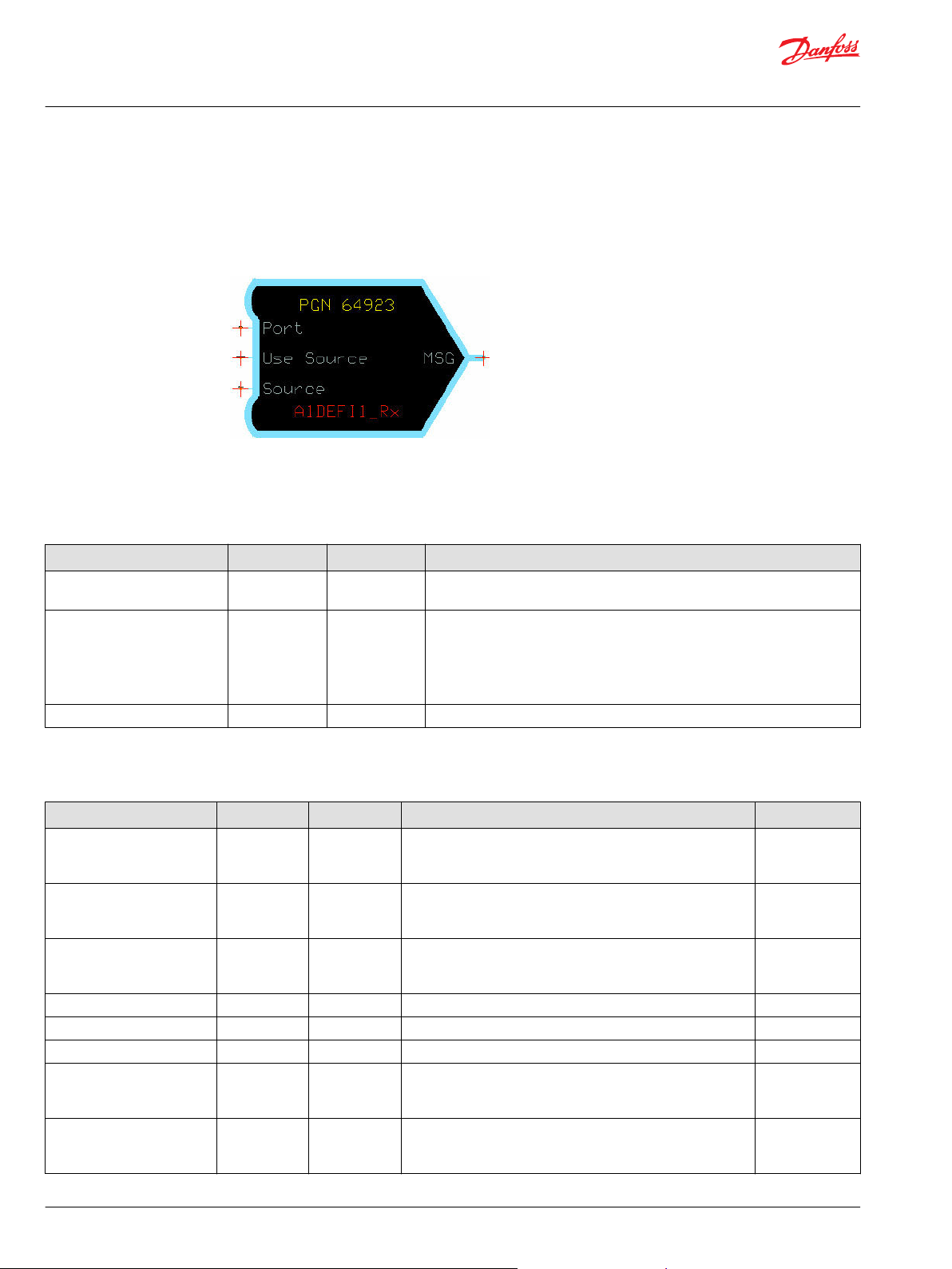
A1DEFI1_Rx—Aftertreatment 1 Diesel Exhaust Fluid Information 1 Receiver
The A1DEFI1_Rx function block receives the A1DEFI1 message.
PGN: 64923 (0xFD9B)
Inputs The inputs to the A1DEFI1_Rx function block are described.
Name Type Range Description
Port Port —— Determines which physical CAN port of the hardware is used to receive the
message.
Use Source BOOL T/F Determines if messages are received from any source or just from the one
specified in Source.
•
T: Only receive this message when transmitted from the address specified by
Source.
•
F: Receive this message from any address.
Source —— 0-253 Address of the transmitting device. Only applies if Use Source is True.
Outputs The outputs of the A1DEFI1_Rx function block are described.
Name Type Range Description [Unit]
DslExhstFldTmp2 S16 -40-210 Diesel Exhaust Fluid Temperature 2.
Resolution: 1° C
[° C]
DslExhstFldCncntrtn U16 0-6250 Diesel Exhaust Fluid Concentration.
Resolution: 0.25%
[0.01%]
DslExhstFldCndctvty U16 0-1250 Diesel Exhaust Fluid Conductivity.
Resolution: 5 µSiemens/mm
[1 µSiemens/mm]
DslExhstFldTemp2PrelFMI U8 0-31 Diesel Exhaust Fluid Temperature 2 Preliminary FMI. 3519
DslExhstFldPrprtsPrelFMI
DslExhstFldPrprty U8 0-15 Diesel Exhaust Fluid Property. 3521
DslExhstFldSpdSnd S32 0-64255 Diesel Exhaust Fluid Speed of Sound.
Rx_A1DEFI1
U8 0-31 Diesel Exhaust Fluid Properties Preliminary FMI. 3520
Resolution: 0.1 m/s
[0.1 m/s]
BOOL T/F True for the first cycle that new data is received.
T: Received new data.
F: Did not receive new data.
SPN
3515
3516
3518
7346
——
10 | © Danfoss | September 2019 11023438 | AQ310885477127en-000101
Page 11
User Manual
PLUS+1® Function Block Library—J1939 Function Blocks
PGN Receivers
Name Type Range Description [Unit]
Status BUS —— The Status bus contains information for each input that is
transmitted in the message.
If the SignalName_NA is true, then that signal is not available.
Fault BUS —— The Fault bus contains information for each input that is
transmitted in the message.
If the SignalName_Flt is true, then a fault condition exists for
this signal.
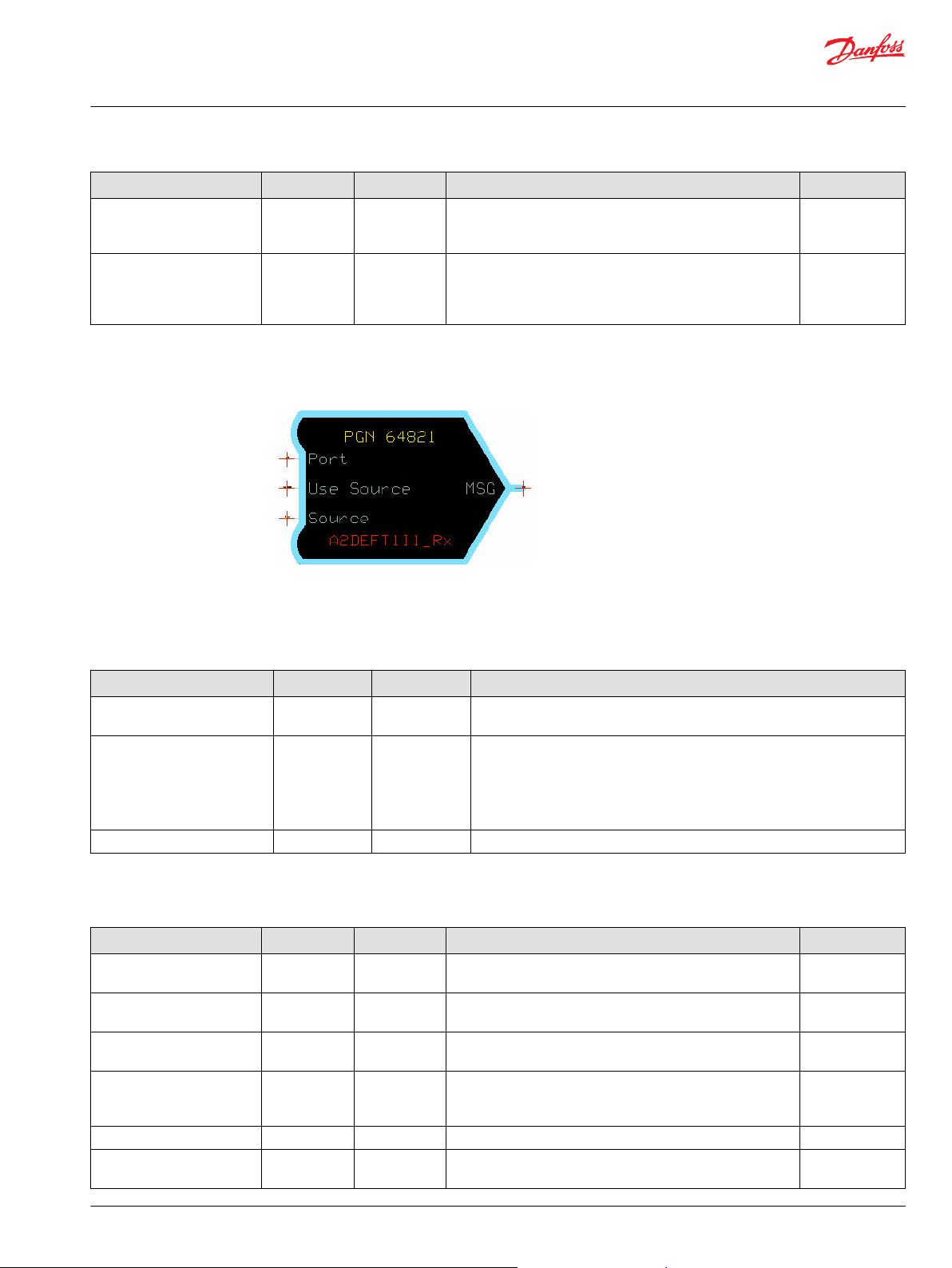
A2DEFT1I1_Rx—Aftertreatment 2 Diesel Exhaust Fluid Tank 1 Information For Receiver
The A2DEFT1I1_Rx function block receives the A2DEFT1I1 message.
PGN: 64821 (0xFD35)
Inputs The inputs to the A2DEFT1I1_Rx function block are described.
SPN
——
——
Name Type Range Description
Port Port —— Determines which physical CAN port of the hardware is used to receive the
message.
Use Source BOOL T/F Determines if messages are received from any source or just from the one
specified in Source.
•
T: Only receive this message when transmitted from the address specified by
Source.
•
F: Receive this message from any address.
Source —— 0-253 Address of the transmitting device. Only applies if Use Source is True.
Outputs The outputs of the A2DEFT1I1 function block are described.
Name Type Range Description [Unit]
Volume
Temp
Level
FMI_Vol_Level
FMI_Temp
Heater
U16 0-10000 Aftertreatment 2 Diesel Exhaust Fluid Tank Volume.
[0.01%]
S16 -40-210 Aftertreatment 2 Diesel Exhaust Fluid Tank Temperature.
[° C]
U16 0-64255 Aftertreatment 2 Diesel Exhaust Fluid Tank Level.
[0.1 mm]
U8 0-31 Aftertreatment 2 Diesel Exhaust Fluid Tank Volume/Level
Preliminary FMI.
A volume of 31 indicates no failure or not supported.
U8 0-31 Aftertreatment 2 Diesel Exhaust Fluid Tank Temperature. 4430
U16 0-10000 Aftertreatment 2 Diesel Exhaust Fluid Tank Heater.
[0.01%]
SPN
4426
4427
4428
4429
4431
©
Danfoss | September 2019 11023438 | AQ310885477127en-000101 | 11
Page 12
User Manual
PLUS+1® Function Block Library—J1939 Function Blocks
PGN Receivers
Name Type Range Description [Unit]
FMI_Heater
Rx_A2DEFT1I1
Status BUS —— The Status bus contains information for each input that is
Fault BUS —— The Fault bus contains information for each input that is
U8 0-31 Aftertreatment 2 Diesel Exhaust Fluid Tank 1 Heater Preliminary
FMI.
A value of 31 indicates no failure or not supported.
BOOL T/F True for the first cycle that new data is received.
T: Received new data.
F: Did not receive new data.
transmitted in the message.
If the SignalName_NA is true, then that signal is not available.
transmitted in the message.
If the SignalName_Flt is true, then a fault condition exists for
this signal.
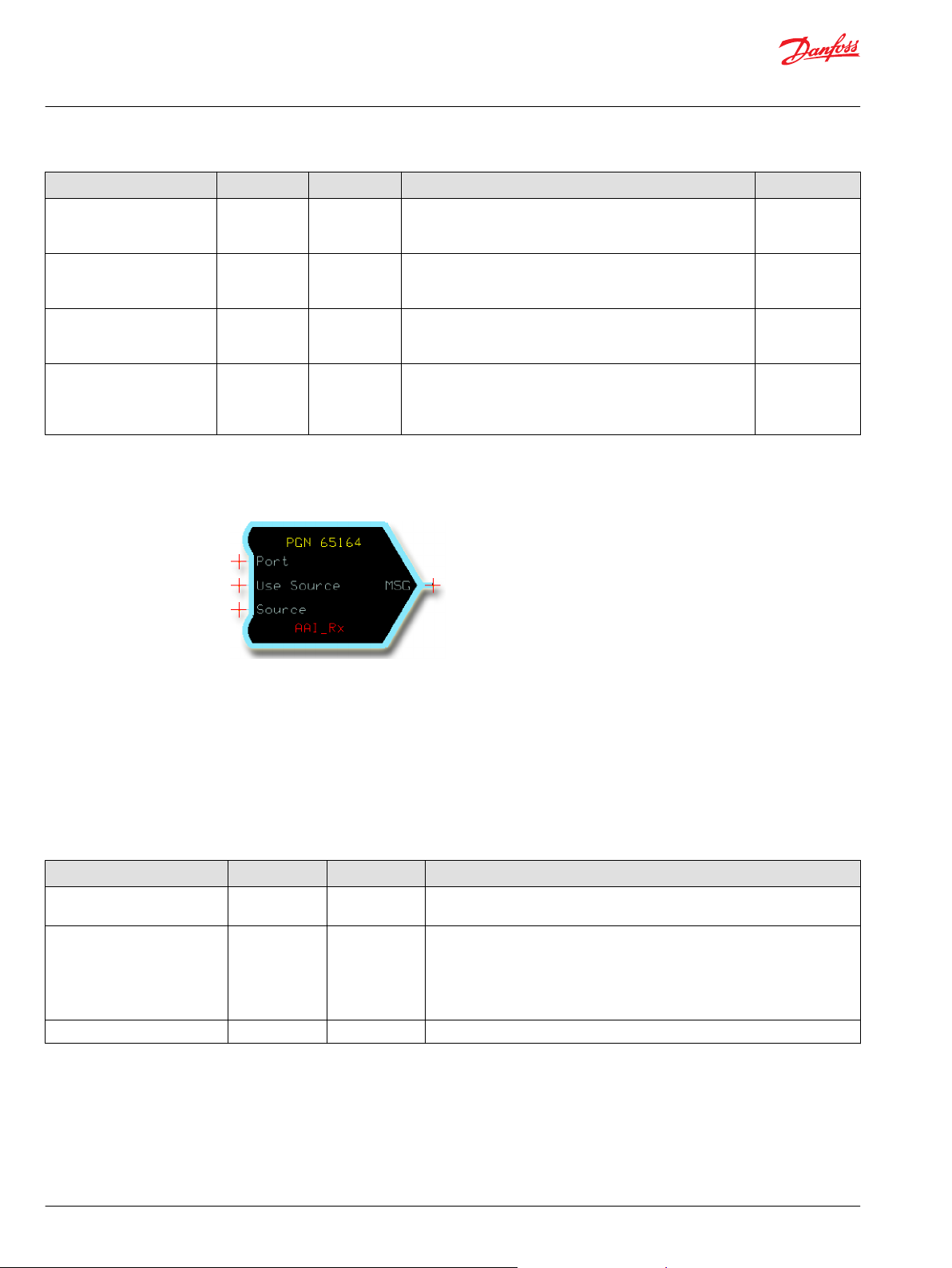
AAI_Rx—Auxiliary Analog Information Receiver
The AAI_Rx function block receives the AAI message defined by J1939-DA.
SPN
4432
——
——
——
It provides data signals scaled to application-compatible formats. If data is not available or has an error,
the function block also reports this.
PGN: 65164 (0xFE8C)
CAN message timeout detection is not included in this function block.
The application can detect this by monitoring the Rx_AAI signal.
Inputs The inputs to the AAI_Rx function block are described.
Name Type Range Description
Port Port —— Determines which physical CAN port of the hardware is used to receive the
message.
Use Source BOOL T/F Determines if messages are received from any source or just from the one
specified in Source.
•
T: Only receive this message when transmitted from the address specified by
Source.
•
F: Receive this message from any address.
Source —— 0–255 Address of the transmitting device. Only applies if Use Source is True.
12 | © Danfoss | September 2019 11023438 | AQ310885477127en-000101
Page 13
User Manual
PLUS+1® Function Block Library—J1939 Function Blocks
PGN Receivers
Outputs The outputs of the AAI_Rx function block are described.
Name Type Range Description [Unit] SPN
AuxTemp1 S16 -40–210 Auxiliary Temperature 1
[° C]
AuxTemp2 S16 -40–210 Auxiliary Temperature 2.
[° C]
AuxPress1 U16 0–4000 Auxiliary Pressure 1.
[kPa]
AuxPress2 U16 0–4000 Auxiliary Pressure 2.
[kPa]
AuxLevel U16 0–64255 Auxiliary Level
[0.1 mm]
RelHumidity U16 0–10000 Relative Humidity
[0.01%]
Rx_AAI BOOL T/F True for the first cycle that new data is received.
T: Received new data.
F: Did not receive new data.
Status BUS —— The Status bus contains information for each input that is
transmitted in the message.
If the SignalName _NA is true, then that signal is not available.
Fault BUS —— The Fault bus contains information for each input that is transmitted
in the message.
If the SignalName _Flt is true, this indicates a fault condition exists
for this signal.
441
442
1387
1388
3087
354
——
——
——
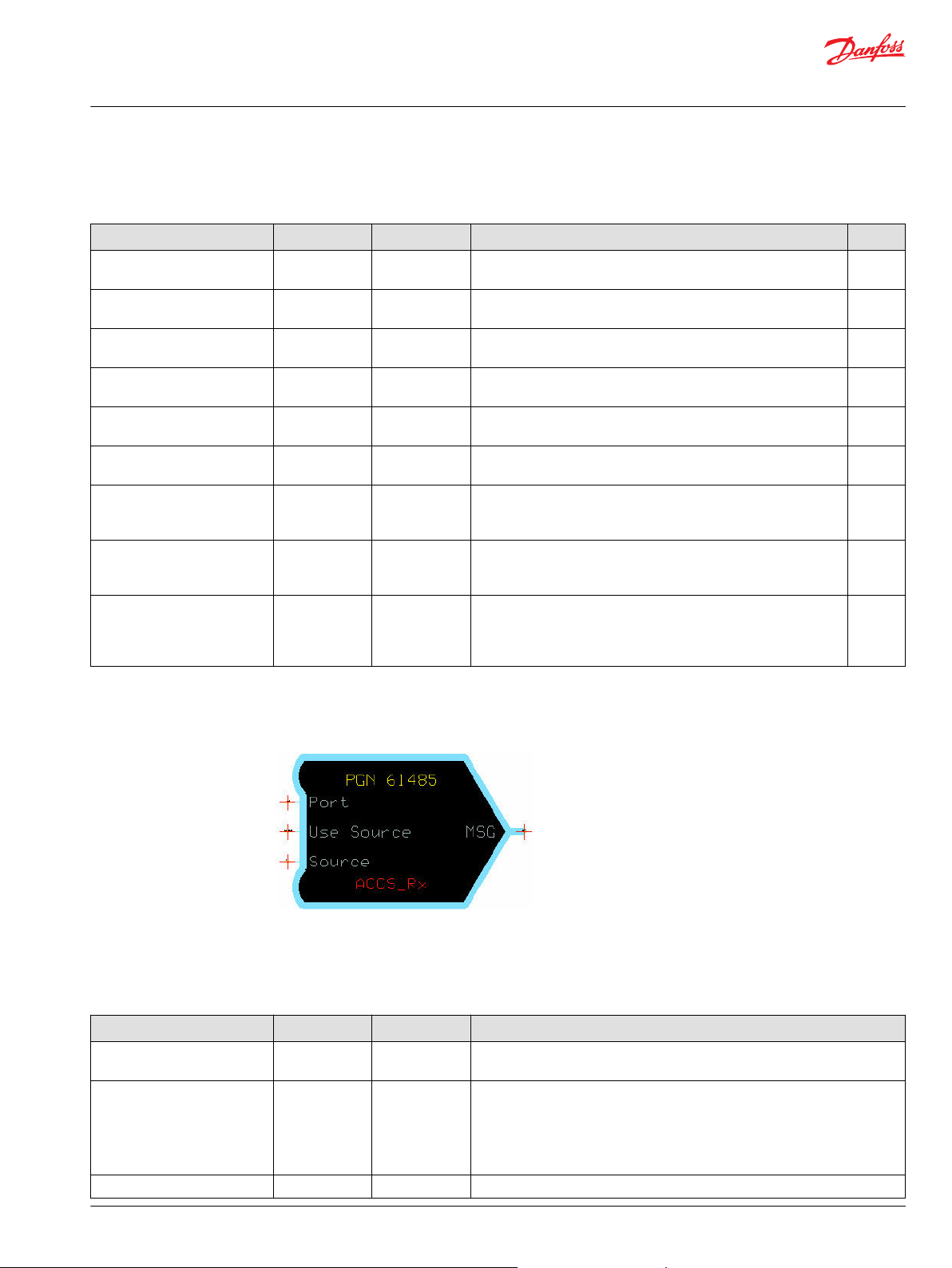
ACCS_Rx—Acceleration Sensor Receiver
The ACCS_Rx function block receives the ACCS message.
PGN: 61485 (0xF02D)
Inputs The inputs to the ACCS_Rx function block are described.
Name Type Range Description
Port Port —— Determines which physical CAN port of the hardware is used to receive the
message.
Use Source BOOL T/F Determines if messages are received from any source or just from the one
specified in Source.
•
T: Only receive this message when transmitted from the address specified by
Source.
•
F: Receive this message from any address.
Source —— 0–255 Address of the transmitting device. Only applies if Use Source is True.
©
Danfoss | September 2019 11023438 | AQ310885477127en-000101 | 13
Page 14
User Manual
PLUS+1® Function Block Library—J1939 Function Blocks
PGN Receivers
Outputs The outputs of the ACCS_Rx function block are described.
Name Type Range Description [Unit] SPN
Lat_Accel S16 -32000-32255 Lateral acceleration along the Y-axis.
[0.01 m/sˆ2]
Long_Accel S16 -32000-32255 Longitudinal acceleration along the X-axis. 5348
Vert_Accel S16 -32000-32255 Vertical acceleration along the Z-axis.
[0.01 m/sˆ2]
Lat_FOM U8 0-3 Figure of merit for lateral acceleration measurement.
0: Fully functional, data is within sensor specification.
1: Degraded, data is suspect.
2: Error.
3: Not available.
Long_FOM U8 0-3 Figure of merit for longitudinal acceleration measurement.
0: Fully functional, data is within sensor specification.
1: Degraded, data is suspect.
2: Error.
3: Not available.
Vert_FOM U8 0-3 Figure of merit for vertical acceleration measurement.
0: Fully functional, data is within sensor specification.
1: Degraded, data is suspect.
2: Error.
3: Not available.
Supp_VTRRAS U8 0-3 Support variable transmission repetition rate for acceleration sensor.
Indicates which transmission rates are supported..
0: Reserved.
1: Reserved.
2: 20 ms rate supported.
3: Device only supports standard 10 ms rate.
Rx_ACCS
Status BUS —— The Status bus contains information for each input that is
Fault BUS —— The Fault bus contains information for each input that is transmitted
BOOL T/F True during the first program cycle that new data is received.
T: Received new data.
F: Did not receive new data.
transmitted in the message.
If the SignalName_NA is true, then that signal is not available.
in the message.
If the SignalName_Flt is true, then a fault condition exists for this
signal.
5347
5349
5350
5351
5352
5353
——
——
——
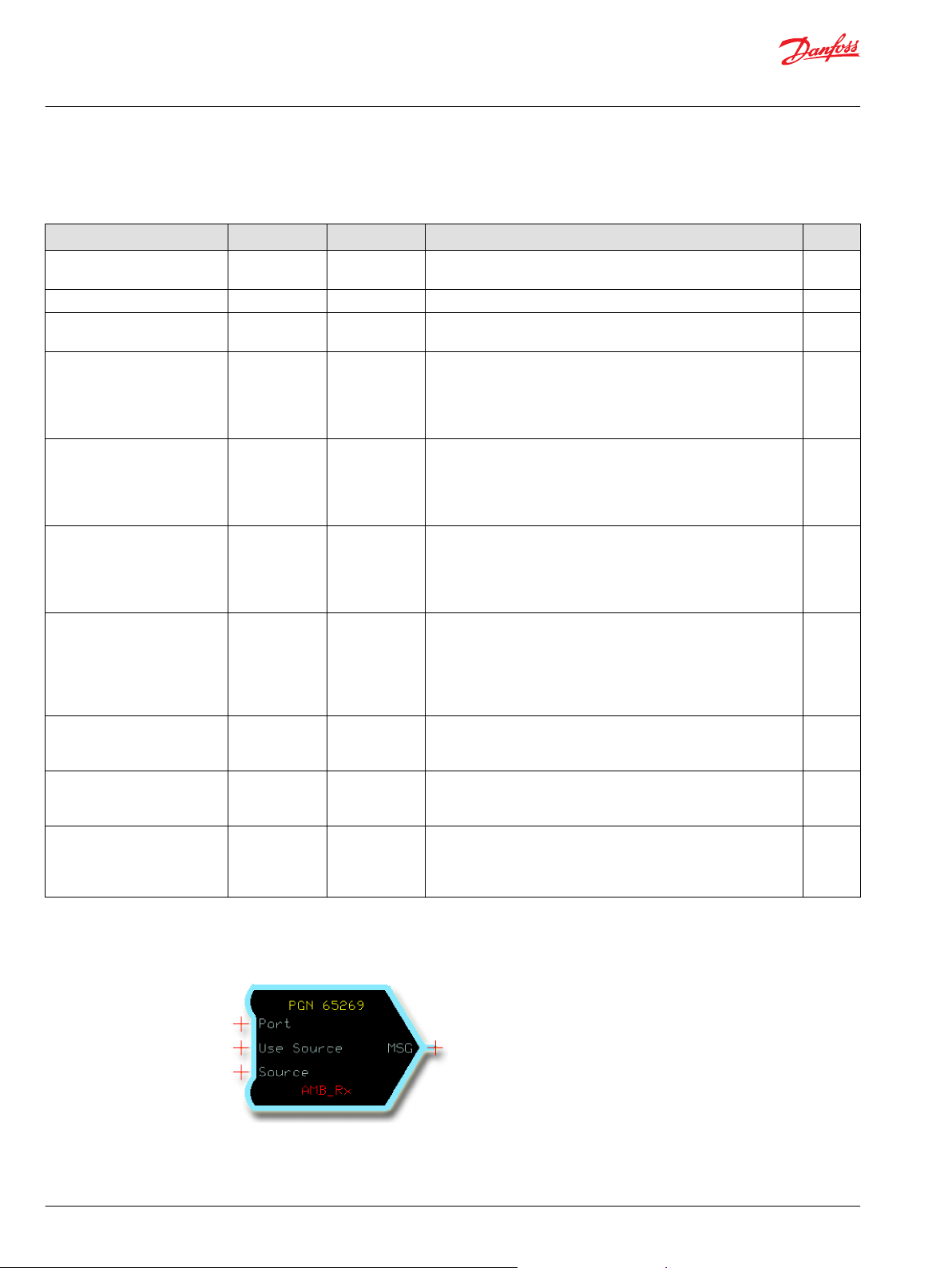
AMB_Rx—Ambient Conditions Receiver
The AMB_Rx function block receives the AMB message defined by J1939-DA.
It provides data signals scaled to application-compatible formats. If data is not available or has an error,
the function block also reports this.
PGN: 65269 (0xFEF5)
14 | © Danfoss | September 2019 11023438 | AQ310885477127en-000101
Page 15
User Manual
PLUS+1® Function Block Library—J1939 Function Blocks
PGN Receivers
CAN message timeout detection is not included in this function block.
The application can detect this by monitoring the Rx_AMB signal.
Inputs The inputs to the AMB_Rx function block are described.
Name Type Range Description
Port Port —— Determines which physical CAN port of the hardware is used to receive the
message.
Use Source BOOL T/F Determines if messages are received from any source or just from the one
specified in Source.
•
T: Only receive this message when transmitted from the address specified by
Source.
•
F: Receive this message from any address.
Source —— 0–255 Address of the transmitting device. Only applies if Use Source is True.
Outputs The outputs of the AMB_Rx function block are described.
Name Type Range Description [Unit] SPN
BarometricP U16 0–1250 Barometric Pressure.
[0.1 kPa]
CabIntTemp S32 -27300000–
173496875
AmbientTemp S32 -27300000–
173496875
EngAirInletT S16 -40–210 Engine Air Inlet Temperature.
RoadSurfaceT S32 -27300000–
173496875
Rx_AMB BOOL T/F True for the first cycle that new data is received.
Status BUS —— The Status bus contains information for each input that is
Fault BUS —— The Fault bus contains information for each input that is transmitted
Cab Interior Temperature.
[0.00001° C]
Ambient Air Temperature.
[0.00001° C]
[° C]
Road Surface Temperature
[0.00001° C]
T: Received new data.
F: Did not receive new data.
transmitted in the message.
If the SignalName _NA is true, then that signal is not available.
in the message.
If the SignalName _Flt is true, this indicates a fault condition exists
for this signal.
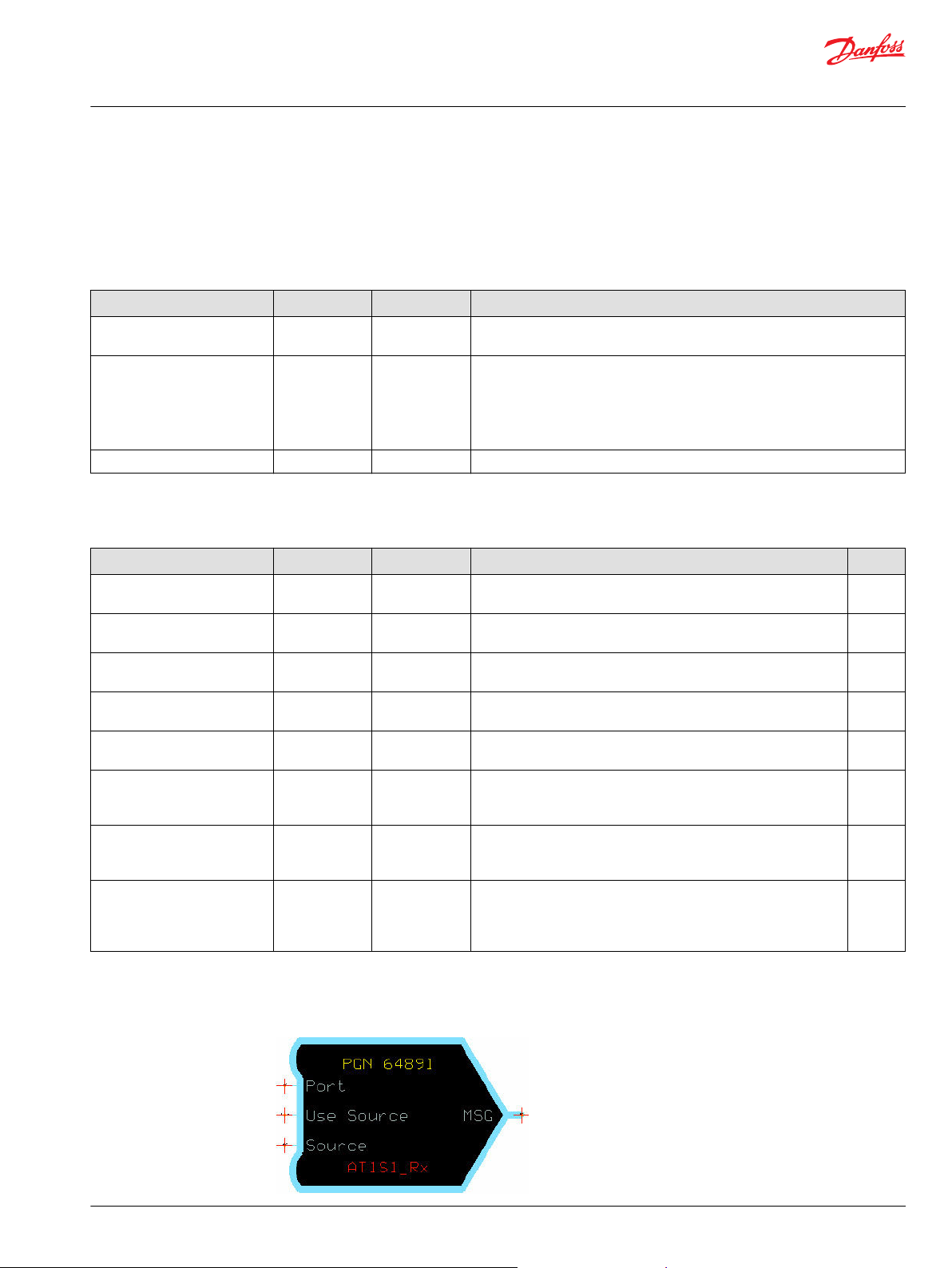
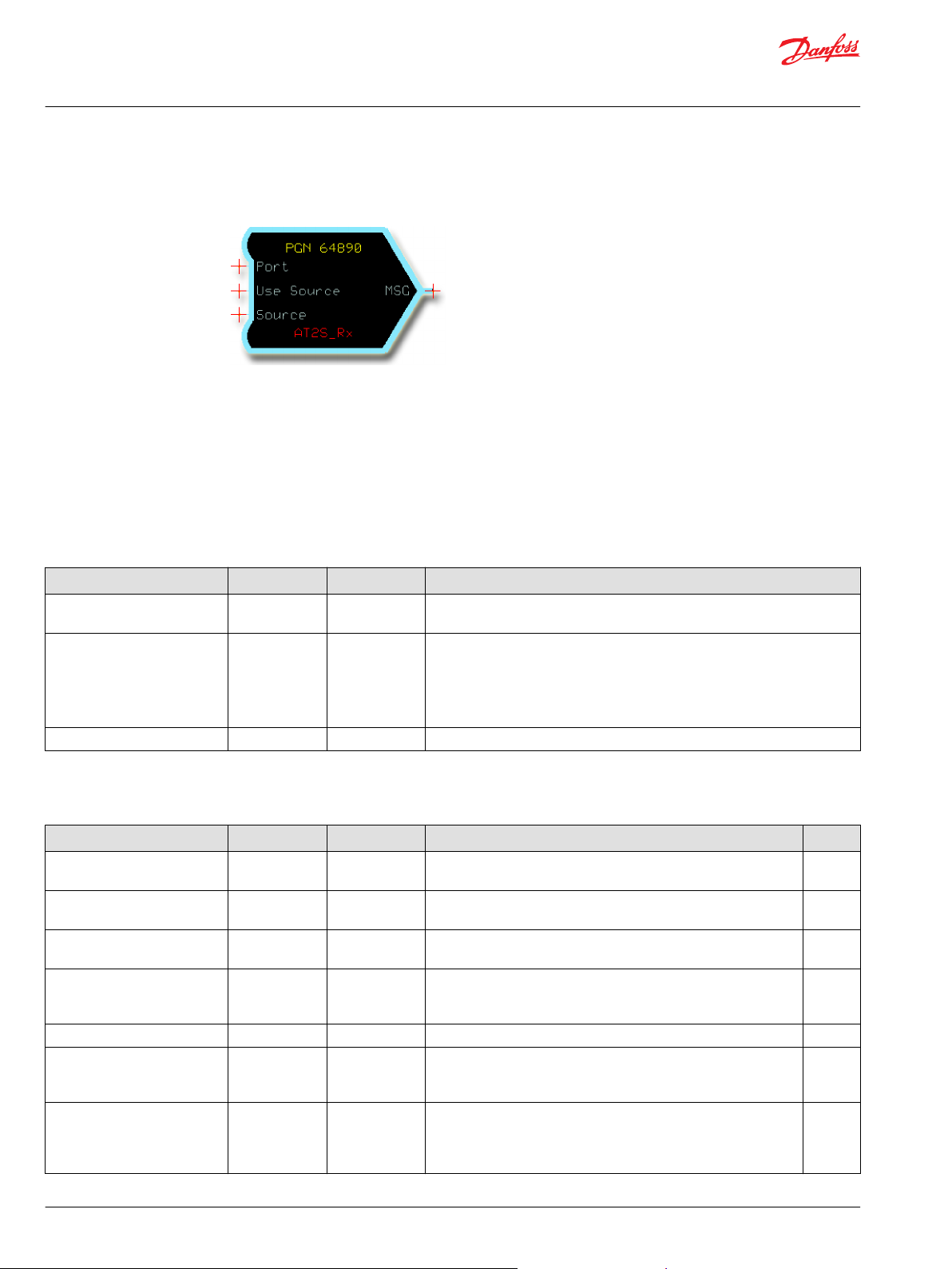
AT1S1_Rx—Aftertreatment 1 Service 1 Receiver
The AT1S1_Rx function block receives the AT1S1 message defined by J1939-DA.
108
170
171
172
79
——
——
——
©
Danfoss | September 2019 11023438 | AQ310885477127en-000101 | 15
Page 16
User Manual
PLUS+1® Function Block Library—J1939 Function Blocks
PGN Receivers
It provides data signals scaled to application-compatible formats. If data is not available or has an error,
the function block also reports this.
PGN: 64891 (0xFD7B)
CAN message timeout detection is not included in this function block.
The application can detect this by monitoring the Rx_AT1S1 signal.
Inputs The inputs to the AT1S_Rx function block are described.
Name Type Range Description
Port Port —— Determines which physical CAN port of the hardware is used to receive the
message.
Use Source BOOL T/F Determines if messages are received from any source or just from the one
specified in Source.
•
T: Only receive this message when transmitted from the address specified by
Source.
•
F: Receive this message from any address.
Source —— 0–255 Address of the transmitting device. Only applies if Use Source is True.
Outputs The outputs of the AT1S1_Rx function block are described.
Name Type Range Description [Unit] SPN
SootLoad1Pct U8 0–250 Diesel Particulate Filter 1 Soot Load Percent.
[ %]
AshLd1Pct U8 0–250 Diesel Particulate Filter 1 Ash Load Percent.
[ %]
TmSinceRegen1 U32 0–4211081215 Diesel Particulate Filter 1 Time Since Last Active Regeneration.
[second]
StLdRegenThr1 U32 0–1606375 Aftertreatment 1 Diesel Particulate Filter Soot Load Regeneration
Threshold.
[0.0001 %]
Rx_AT1S1 BOOL T/F True for the first cycle that new data is received.
T: Received new data.
F: Did not receive new data.
Status BUS —— The Status bus contains information for each input that is
transmitted in the message.
If the SignalName _NA is true, then that signal is not available.
Fault BUS —— The Fault bus contains information for each input that is transmitted
in the message.
If the SignalName _Flt is true, this indicates a fault condition exists
for this signal.
3719
3720
3721
5466
——
——
——
16 | © Danfoss | September 2019 11023438 | AQ310885477127en-000101
Page 17
User Manual
PLUS+1® Function Block Library—J1939 Function Blocks
PGN Receivers
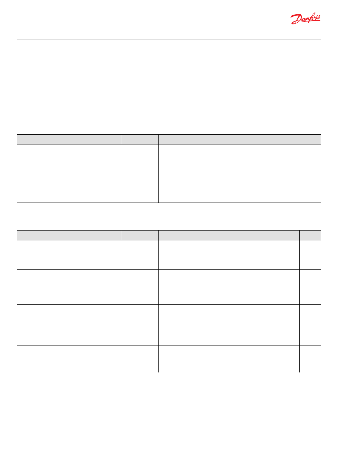
AT1S2_Rx—Aftertreatment 1 Service 2 Receiver
The AT1S2_Rx function block receives the AT1S2 message.
PGN: 64697 (0xFCB9)
Inputs The Inputs to the AT1S2_Rx function block are described.
Name Type Range Description
Port Port —— Determines which physical CAN port of the hardware is used to receive the
message.
Use Source BOOL T/F Determines if messages are received from any source or just from the one
specified in Source.
•
T: Only receive this message when transmitted from the address specified by
Source.
•
F: Receive this message from any address.
Source —— 0–255 Address of the transmitting device. Only applies if Use Source is True.
Outputs The outputs of the AT1S2_Rx function block are described.
Name Type Range Description [Unit] SPN
DslPartFltrTimeToReg U32 0-4211081215 Diesel Particulate Filter Time to Next Active Regeneration.
Resolution: 1 second
[second]
SCRSystemTimeLastCleanEv U32 0-4211081215 SCR System Time Since Last System Cleaning Event.
Resolution: 1 second
[second]
Rx_AT1S2 BOOL T/F True for the first cycle that new data is received.
T: Received new data.
F: Did not receive new data.
Status BUS —— The Status bus contains information for each input that is
transmitted in the message.
If the SignalName_NA is true, then that signal is not available.
Fault BUS —— The Fault bus contains information for each input that is transmitted
in the message.
If the SignalName_Flt is true, then a fault condition exists for this
signal.
5978
6941
——
——
——
©
Danfoss | September 2019 11023438 | AQ310885477127en-000101 | 17
Page 18
User Manual
PLUS+1® Function Block Library—J1939 Function Blocks
PGN Receivers
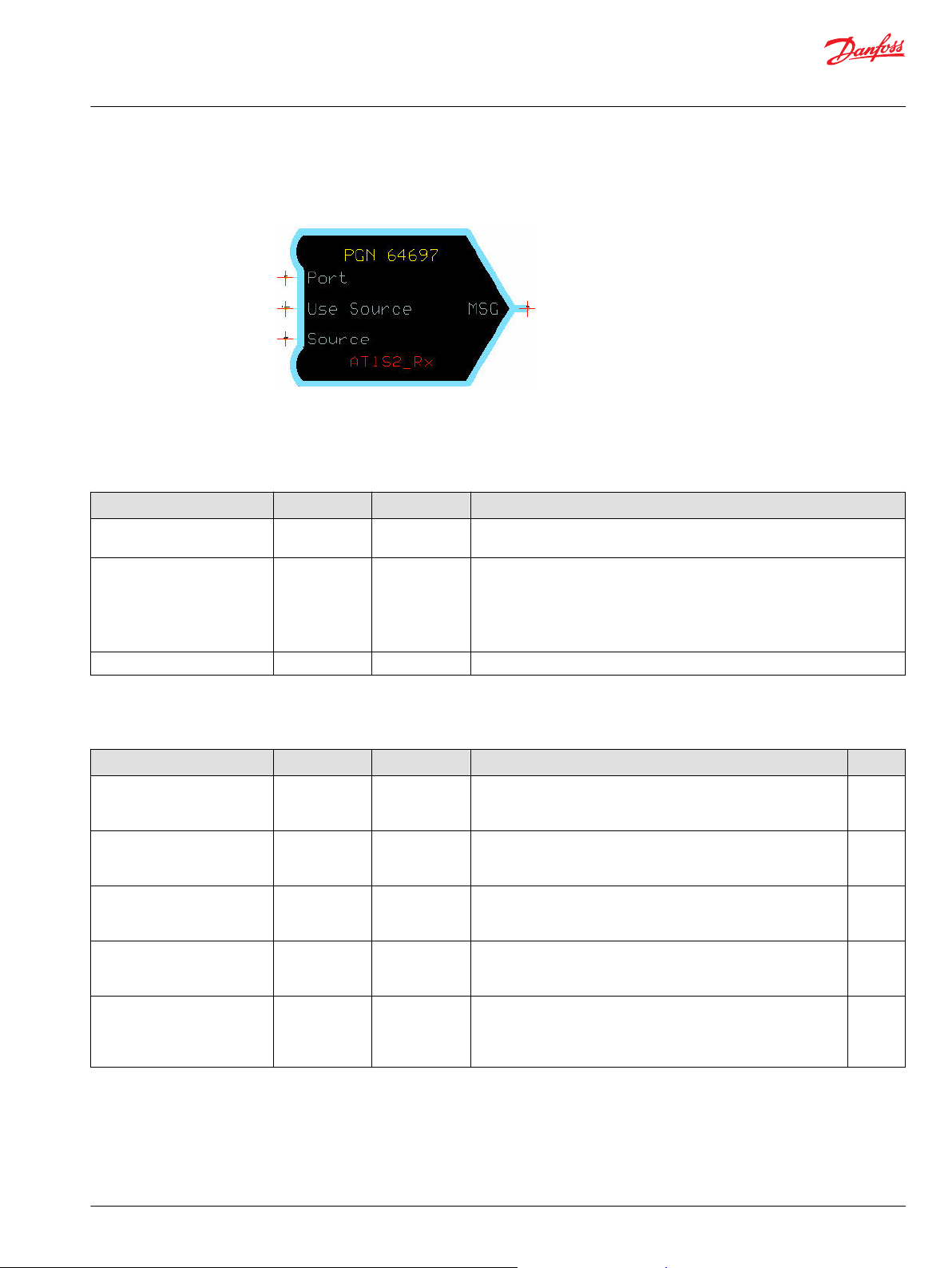
AT2S_Rx—Aftertreatment 2 Service Receiver
The AT2S_Rx function block receives the AT2S message defined by J1939-DA.
It provides data signals scaled to application-compatible formats. If data is not available or has an error,
the function block also reports this.
PGN: 64890 (0xFD7A)
CAN message timeout detection is not included in this function block.
The application can detect this by monitoring the Rx_AT2S signal.
Inputs The inputs to the AT2S_Rx function block are described.
Name Type Range Description
Port Port —— Determines which physical CAN port of the hardware is used to receive the
message.
Use Source BOOL T/F Determines if messages are received from any source or just from the one
specified in Source.
•
T: Only receive this message when transmitted from the address specified by
Source.
•
F: Receive this message from any address.
Source —— 0–255 Address of the transmitting device. Only applies if Use Source is True.
Outputs The outputs of the AT2S_Rx function block are described.
Name Type Range Description [Unit] SPN
SootLoad2Pct U8 0–250 Diesel Particulate Filter 2 Soot Load Percent
[ %]
AshLd2Pct U8 0–250 Diesel Particulate Filter 2 Ash Load Percent
[ %]
TmSinceRegen2 U32 0–4211081215 Diesel Particulate Filter 2 Time Since Last Active Regeneration
[second]
StLdRegenThr2 U32 0–1606375 Aftertreatment 2 Diesel Particulate Filter Soot Load Regeneration
Threshold
[0.0001 %]
Rx_AT2S BOOL T/F True during the first program cycle that new data is received. ——
Status BUS —— The Status bus contains information for each input that is
transmitted in the message.
If the SignalName _NA is true, then that signal is not available.
Fault BUS —— The Fault bus contains information for each input that is transmitted
in the message.
If the SignalName _Flt is true, this indicates a fault condition exists
for this signal.
3722
3723
3724
5467
——
——
18 | © Danfoss | September 2019 11023438 | AQ310885477127en-000101
Page 19
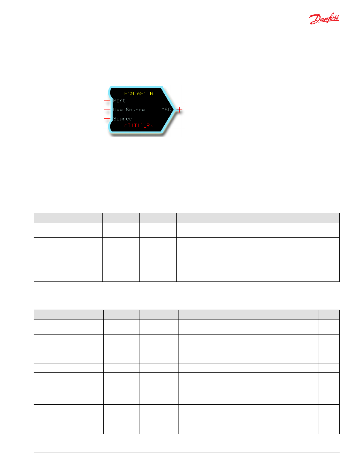
User Manual
PLUS+1® Function Block Library—J1939 Function Blocks
PGN Receivers
AT1T1I_Rx—Aftertreatment 1 Diesel Exhaust Fluid Tank 1 Information Receiver
The AT1T1I_Rx function block receives the AT1T1I_Rx message defined by J1939-DA.
It provides data signals scaled to application-compatible formats. If data is not available or has an error,
the function block also reports this.
PGN: 65110 (0xFE56)
CAN message timeout detection is not included in this function block.
The application can detect this by monitoring the Rx_AT1T1I signal.
Inputs The inputs to the AT1T1I_Rx function block are described.
Name Type Range Description
Port Port —— Determines which physical CAN port of the hardware is used to receive the
message.
Use Source BOOL T/F Determines if messages are received from any source or just from the one
specified in Source.
•
T: Only receive this message when transmitted from the address specified by
Source.
•
F: Receive this message from any address.
Source —— 0–255 Address of the transmitting device. Only applies if Use Source is True.
Outputs The outputs of the AT1T1l_Rx function block are described.
Name Type Range Description [Unit] SPN
Level U16 0–10000 Aftertreatment 1 Diesel Exhaust Fluid Tank 1 Level.
[0.01%]
Temperature S16 -40–210 Aftertreatment 1 Diesel Exhaust Fluid Tank 1 Temperature.
[° C]
Level_2 U16 0–64255 Aftertreatment 1 Diesel Exhaust Fluid Tank Level 2.
[0.1 mm]
LevelPrelimFM1 U8 0–31 Aftertreatment 1 Diesel Exhaust Fluid Tank Level Preliminary FMI. 3532
LowLevelIndicator U8 0–7 Aftertreatment 1 Diesel Exhaust Fluid Tank 1 Low Level Indicator. 5245
TempPrelimFMI U8 0–31 Aftertreatment 1 Diesel Exhaust Fluid Tank 1 Temperature
Preliminary FMI.
SCROperInducSeverity U8 0–7 Aftertreatment SCR Operator Inducement Severity. 5246
Heater U16 0–10000 Aftertreatment SCR Operator Inducement Tank 1 Heater.
[0.01%]
HeaterPrelimFMI U8 0–31 Aftertreatment SCR Operator Inducement Tank 1 Heater Preliminary
FMI.
1761
3031
3517
4365
3363
4366
©
Danfoss | September 2019 11023438 | AQ310885477127en-000101 | 19
Page 20
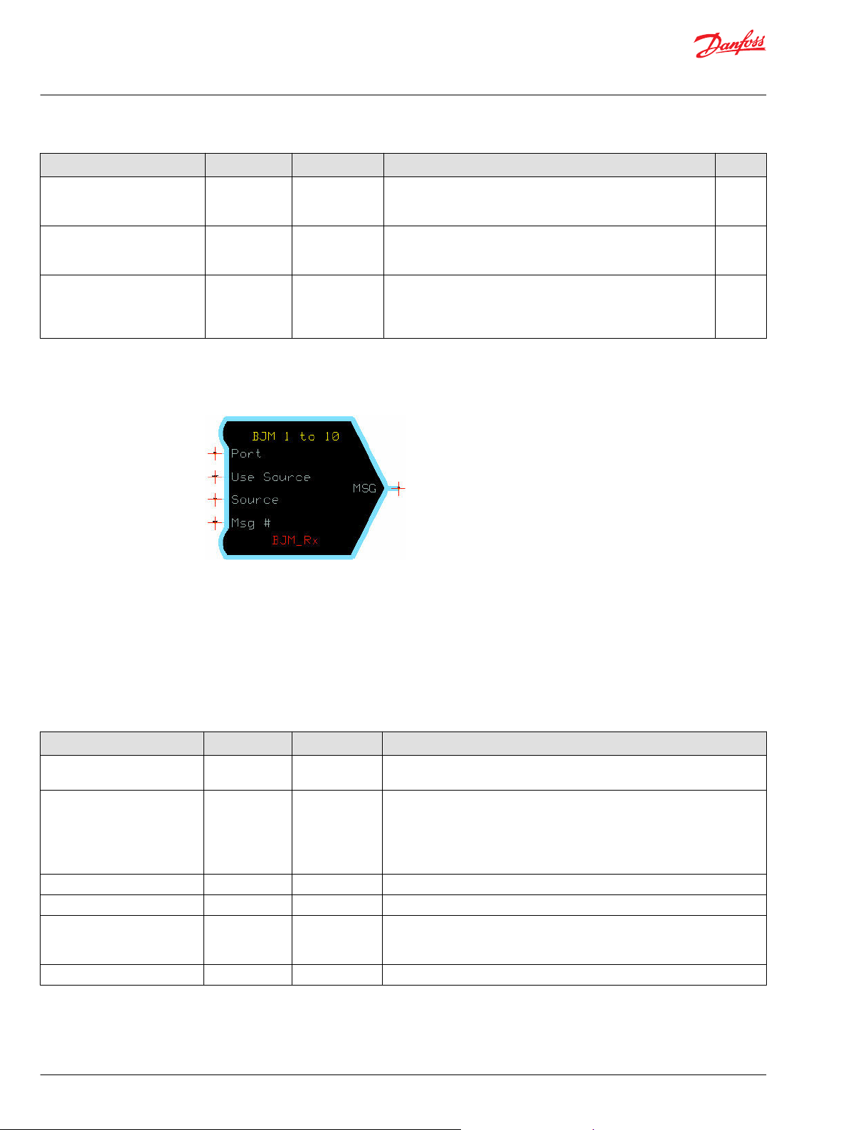
User Manual
PLUS+1® Function Block Library—J1939 Function Blocks
PGN Receivers
Name Type Range Description [Unit] SPN
Rx_AT1T1I BOOL T/F True for the first cycle that new data is received.
T: Received new data.
F: Did not receive new data.
Status BUS —— The Status bus contains information for each input that is
transmitted in the message.
If the SignalName _NA is true, then that signal is not available.
Fault BUS —— The Fault bus contains information for each input that is
transmitted in the message.
If the SignalName _Flt is true, this indicates a fault condition exists
for this signal.
BJM_Rx—Basic Joystick Message Receiver
The BJM_Rx function block receives the BJM message defined by J1939-DA.
——
——
——
It provides data signals scaled to application-compatible formats. If data is not available or has an error,
the function block also reports this.
CAN message timeout detection is included in this function block.
This block reports all signals as Not Available previous to receiving data from the joystick when the
application starts.
Inputs The inputs to the BJM_Rx function block are described.
Name Type Range Description
Port Port —— Determines which physical CAN port of the hardware is used to receive the
message.
Use Source BOOL T/F Determines if messages are received from any source or just from the one
specified in Source.
•
T: Only receive this message when transmitted from the address specified by
Source.
•
F: Receive this message from any address.
Source —— 0–255 Address of the transmitting device. Only applies if Use Source is True.
Msg Num
Protected
Time Out
U8 1-10 Messages are received for this basic joystick number.
BOOL T/F Save the first message or save the last message.
T: Saves the first message received in the loop.
F: Saves the last message received in the loop.
U16 0–10000 Maximum time, in ms, between messages before a timeout fault is triggered.
20 | © Danfoss | September 2019 11023438 | AQ310885477127en-000101
Page 21
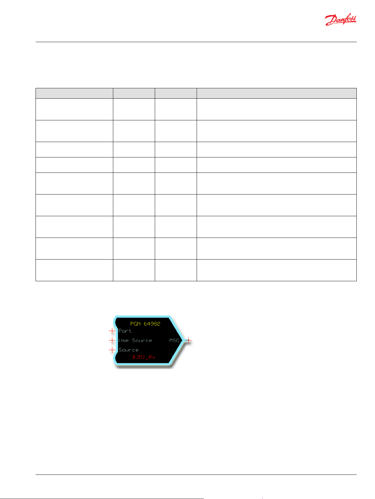
User Manual
PLUS+1® Function Block Library—J1939 Function Blocks
PGN Receivers
Outputs The outputs of the BJM_Rx function block are described.
Name Type Range Description [Unit]
Status BUS —— The Status bus contains information for each input that is transmitted in
the message.
If the SignalName_NA is true, then that signal is not available.
Fault
X_Axis_Psn
Y_Axis_Psn
X_Axis_Det
Y_Axis_Det
Btn
Rx_BJM
Status BUS —— Bitwise code where multiple items can be reported at a time.
BUS —— The Fault bus contains information for each input that is transmitted in
the message.
If the SignalName_Flt is true, then a fault condition exists for this signal.
S16 -10000-10000 Joystick X-Axis Position.
[0.01%]
S16 -10000-10000 Joystick Y-Axis Position.
[0.01%]
BOOL T/F Joystick X-Axis Detent Switch.
T: Active.
F: Inactive.
BOOL T/F Joystick Y-axis detent switch.
T: Active.
F: Inactive.
BOOL T/F Joystick Buttons 1 to 12.
T: Button X is pressed.
F: Button X is released.
BOOL T/F True during the first program cycle that new data is received.
T: Received new data.
F: Did not receive new data.
0x0000: Status OK.
0x8008: At least one parameter is out of range.
BJM1_Rx—Basic Joystick Message 1 Receiver
The BJM1_Rx function block receives the BJM1 message defined by J1939-DA.
It provides data signals scaled to application-compatible formats. If data is not available or has an error,
the function block also reports this.
PGN: 64982 (0xFDD6)
CAN message timeout detection is included in this function block.
This block reports all signals as Not Available previous to receiving data from the joystick when the
application starts.
©
Danfoss | September 2019 11023438 | AQ310885477127en-000101 | 21
Page 22

User Manual
PLUS+1® Function Block Library—J1939 Function Blocks
PGN Receivers
Inputs The inputs to the BJM1_Rx function block are described.
Name Type Range Description
Port Port —— Determines which physical CAN port of the hardware is used to receive the
message.
Use Source BOOL T/F Determines if messages are received from any source or just from the one
specified in Source.
•
T: Only receive this message when transmitted from the address specified by
Source.
•
F: Receive this message from any address.
Source —— 0–255 Address of the transmitting device. Only applies if Use Source is True.
Time Out
U16
0–65535 The Time Out parameter is located on the inside of this function block.
If this function block receives no message within the time set by this
parameter, it:
Sets all its Fault signals to true.
•
Then holds these Fault signals true until it receives another message.
•
Outputs The outputs of the BJM1_Rx function block are described.
Name Type Range Description [Unit] SPN
JS1_X_Axis_Psn S16 -10000–10000 Joystick 1 X-Axis Position.
[0.01%]
JS1_Y_Axis_Psn S16 -10000–10000 Joystick 1 Y-Axis Position.
[0.01%]
JS1_X_Axis_Det BOOL T/F Joystick 1 X-Axis Detent Switch.
T: Active.
F: Inactive.
JS1_Y_Axis_Det BOOL T/F Joystick 1 Y-Axis Detent Switch.
T: Active.
F: Inactive.
JS1_Btn1 BOOL T/F Joystick 1 Button 1 Pressed Status.
T: Button is pressed.
F: Button is released.
JS1_Btn2 BOOL T/F Joystick 1 Button 2 Pressed Status.
T: Button is pressed.
F: Button is released.
JS1_Btn3 BOOL T/F Joystick 1 Button 3 Pressed Status.
T: Button is pressed.
F: Button is released.
JS1_Btn4 BOOL T/F Joystick 1 Button 4 Pressed Status.
T: Button is pressed.
F: Button is released.
JS1_Btn5 BOOL T/F Joystick 1 Button 5 Pressed Status.
T: Button is pressed.
F: Button is released.
JS1_Btn6 BOOL T/F Joystick 1 Button 6 Pressed Status.
T: Button is pressed.
F: Button is released.
JS1_Btn7 BOOL T/F Joystick 1 Button 7 Pressed Status.
T: Button is pressed.
F: Button is released.
2660
2661
2680
2681
2685
2686
2687
2688
2689
2690
2691
22 | © Danfoss | September 2019 11023438 | AQ310885477127en-000101
Page 23

User Manual
PLUS+1® Function Block Library—J1939 Function Blocks
PGN Receivers
Name Type Range Description [Unit] SPN
JS1_Btn8 BOOL T/F Joystick 1 Button 8 Pressed Status.
T: Button is pressed.
F: Button is released.
JS1_Btn9 BOOL T/F Joystick 1 Button 9 Pressed Status.
T: Button is pressed.
F: Button is released.
JS1_Btn10 BOOL T/F Joystick 1 Button 10 Pressed Status.
T: Button is pressed.
F: Button is released.
JS1_Btn11 BOOL T/F Joystick 1 Button 11 Pressed Status.
T: Button is pressed.
F: Button is released.
JS1_Btn12 BOOL T/F Joystick 1 Button 12 Pressed Status.
T: Button is pressed.
F: Button is released.
Rx_BJM1 BOOL T/F True for the first cycle that new data is received.
T: Received new data.
F: Did not receive new data.
Status BUS —— The Status bus contains information for each input that is
transmitted in the message.
If the SignalName _NA is true, then that signal is not available.
Fault BUS —— The Fault bus contains information for each input that is transmitted
in the message.
If the SignalName _Flt is true, this indicates a fault condition exists
for this signal.
2692
2693
2694
2695
2696
——
——
——
BJM2_Rx—Basic Joystick Message 2 Receiver
The BJM2_Rx function block receives the BJM2 message defined by J1939-DA.
It provides data signals scaled to application-compatible formats. If data is not available or has an error,
the function block also reports this.
PGN: 64984 (0xFDD8)
CAN message timeout detection is included in this function block.
This block reports all signals as Not Available previous to receiving data from the joystick when the
application starts.
©
Danfoss | September 2019 11023438 | AQ310885477127en-000101 | 23
Page 24

User Manual
PLUS+1® Function Block Library—J1939 Function Blocks
PGN Receivers
Inputs The inputs to the BJM2_Rx function block are described.
Name Type Range Description
Port Port —— Determines which physical CAN port of the hardware is used to receive the
message.
Use Source BOOL T/F Determines if messages are received from any source or just from the one
specified in Source.
•
T: Only receive this message when transmitted from the address specified by
Source.
•
F: Receive this message from any address.
Source —— 0–255 Address of the transmitting device. Only applies if Use Source is True.
Time Out
U16
0–65535 The Time Out parameter is located on the inside of this function block.
If this function block receives no message within the time set by this
parameter, it:
Sets all its Fault signals to true.
•
Then holds these Fault signals true until it receives another message.
•
Outputs The outputs of the BJM2_Rx function block are described.
Name Type Range Description [Unit] SPN
JS2_X_Axis_Psn S16 -10000–10000 Joystick 2 X-Axis Position.
[0.01%]
JS2_Y_Axis_Psn S16 -10000–10000 Joystick 2 Y-Axis Position.
[0.01%]
JS2_X_Axis_Det BOOL T/F Joystick 2 X-Axis Detent Switch.
T: Active.
F: Inactive.
JS2_Y_Axis_Det BOOL T/F Joystick 2 Y-Axis Detent Switch.
T: Active.
F: Inactive.
JS2_Btn1 BOOL T/F Joystick 2 Button 1 Pressed Status
T: Button is pressed.
F: Button is released.
JS2_Btn2 BOOL T/F Joystick 2 Button 2 Pressed Status.
T: Button is pressed.
F: Button is released.
JS2_Btn3 BOOL T/F Joystick 2 Button 3 Pressed Status.
T: Button is pressed.
F: Button is released.
JS2_Btn4 BOOL T/F Joystick 2 Button 4 Pressed Status.
T: Button is pressed.
F: Button is released.
JS2_Btn5 BOOL T/F Joystick 2 Button 5 Pressed Status.
T: Button is pressed.
F: Button is released.
JS2_Btn6 BOOL T/F Joystick 2 Button 6 Pressed Status.
T: Button is pressed.
F: Button is released.
JS2_Btn7 BOOL T/F Joystick 2 Button 7 Pressed Status.
T: Button is pressed.
F: Button is released.
2697
2698
2717
2718
2722
2723
2724
2725
2726
2727
2728
24 | © Danfoss | September 2019 11023438 | AQ310885477127en-000101
Page 25
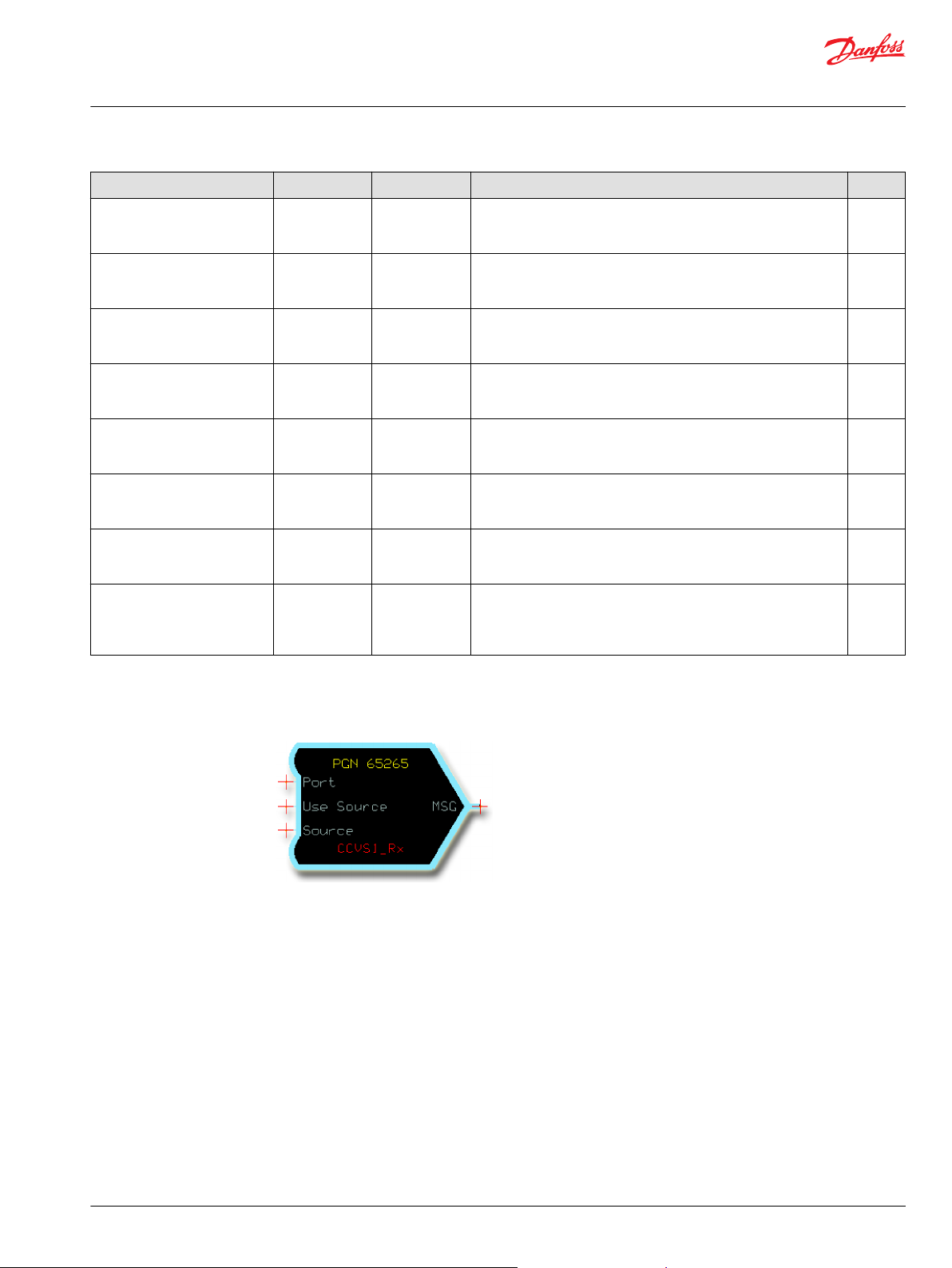
User Manual
PLUS+1® Function Block Library—J1939 Function Blocks
PGN Receivers
Name Type Range Description [Unit] SPN
JS2_Btn8 BOOL T/F Joystick 2 Button 8 Pressed Status.
T: Button is pressed.
F: Button is released.
JS2_Btn9 BOOL T/F Joystick 2 Button 9 Pressed Status.
T: Button is pressed.
F: Button is released.
JS2_Btn10 BOOL T/F Joystick 2 Button 10 Pressed Status.
T: Button is pressed.
F: Button is released.
JS2_Btn11 BOOL T/F Joystick 2 Button 11 Pressed Status.
T: Button is pressed.
F: Button is released.
JS2_Btn12 BOOL T/F Joystick 2 Button 12 Pressed Status.
T: Button is pressed.
F: Button is released.
Rx_BJM2 BOOL T/F True during the first program cycle that new data is received.
T: Received new data.
F: Did not receive new data.
Status BUS —— The Status bus contains information for each input that is
transmitted in the message.
If the SignalName _NA is true, then that signal is not available.
Fault BUS —— The Fault bus contains information for each input that is transmitted
in the message.
If the SignalName _Flt is true, this indicates a fault condition exists
for this signal.
2729
2730
2731
2732
2733
——
——
——
CCVS1_Rx—Cruise Control/Vehicle Speed 1 Receiver
The CCVS1_Rx function block receives the CCVS1 message defined by J1939-DA.
It provides data signals scaled to application-compatible formats. If data is not available or has an error,
the function block also reports this.
PGN: 65265 (0xFEF1)
CAN message timeout detection is not included in this function block.
The application can detect this by monitoring the Rx_CCVS1 signal.
©
Danfoss | September 2019 11023438 | AQ310885477127en-000101 | 25
Page 26

User Manual
PLUS+1® Function Block Library—J1939 Function Blocks
PGN Receivers
Inputs The inputs to the CCVS1_Rx function block are described.
Name Type Range Description
Port Port —— Determines which physical CAN port of the hardware is used to receive the
message.
Use Source BOOL T/F Determines if messages are received from any source or just from the one
specified in Source.
•
T: Only receive this message when transmitted from the address specified by
Source.
•
F: Receive this message from any address.
Source —— 0–255 Address of the transmitting device. Only applies if Use Source is True.
Outputs The outputs of the CCVS1_Rx function block are described.
Name Type Range Description [Unit] SPN
BrakeSwitch BOOL T/F Brake Switch.
T: Active.
F: Inactive.
ClutchSwitch BOOL T/F Clutch Switch.
T: Active.
F: Inactive.
CrCtrlSetSpd U8 0–255 Cruise Control Set Speed.
T: Active.
F: Inactive.
[km/h]
CrsCtrlAccel BOOL T/F Cruise Control Accelerate Switch.
T: Active.
F: Inactive.
CrsCtrlCoast BOOL T/F Cruise Control Coast (Decelerate) Switch.
T: Active.
F: Inactive.
CrsCtrlPause BOOL T/F Cruise Control Pause Switch.
T: Active.
F: Inactive.
CrsCtrlResume BOOL T/F Cruise Control Resume Switch.
T: Active.
F: Inactive.
CrsCtrlSetSw BOOL T/F Cruise Control Set Switch.
T: Active.
F: Inactive.
CrsCtrlState U8 0–6 Cruise Control State:
CruisCtrlAct BOOL T/F Cruise Control Active.
0: Off/disabled.
1: Hold.
2: Accelerate.
3: Decelerate.
4: Resume.
5: Set.
6: Accelerator override.
T: Active.
F: Inactive.
597
598
86
602
600
1633
601
599
527
595
26 | © Danfoss | September 2019 11023438 | AQ310885477127en-000101
Page 27

User Manual
PLUS+1® Function Block Library—J1939 Function Blocks
PGN Receivers
Name Type Range Description [Unit] SPN
CruisCtrlEnbl BOOL T/F Cruise Control Enable Switch.
T: Active.
F: Inactive.
EngIdleDecSw BOOL T/F Engine Idle Decrement Switch.
T: Active.
F: Inactive.
EngIdleIncSw BOOL T/F Engine Idle Increment Switch.
T: Active.
F: Inactive.
EngShtDwOvSw BOOL T/F Engine Shutdown Override Switch.
T: Active.
F: Inactive.
EngTestModSw BOOL T/F Engine Test Mode Switch.
T: Active.
F: Inactive.
PTOState U8 0–19 PTO governor state:
0: Off/disabled.
1: Hold.
2: Remote hold.
3: Standby.
4: Remote standby.
5: Set.
6: Decelerate/coast.
7: Resume.
8: Accelerate.
9: Accelerator override.
10: Preprogrammed set speed 1.
11: Preprogrammed set speed 2.
12: Preprogrammed set speed 3.
13: Preprogrammed set speed 4.
14: Preprogrammed set speed 5.
15: Preprogrammed set speed 6.
16: Preprogrammed set speed 7.
17: Preprogrammed set speed 8.
18: PTO set speed memory 1.
19: PTO set speed memory 2.
ParkBrakeSw BOOL T/F Park Brake Switch.
T: Active.
F: Inactive.
PrkBrkRelInh BOOL T/F Park Brake Release Inhibit Request.
T: Active.
F: Inactive.
TwoSpdAxelSw BOOL T/F Two-Speed Axle Switch.
T: High speed.
F: Low speed.
WhlBasedVSpd U32 0–250996 Wheel Based Vehicle Speed.
[0.001 km/h]
Rx_CCVS1 BOOL T/F True for the first cycle that new data is received.
T: Received new data.
F: Did not receive new data.
596
967
968
1237
966
976
70
3807
69
84
——
©
Danfoss | September 2019 11023438 | AQ310885477127en-000101 | 27
Page 28
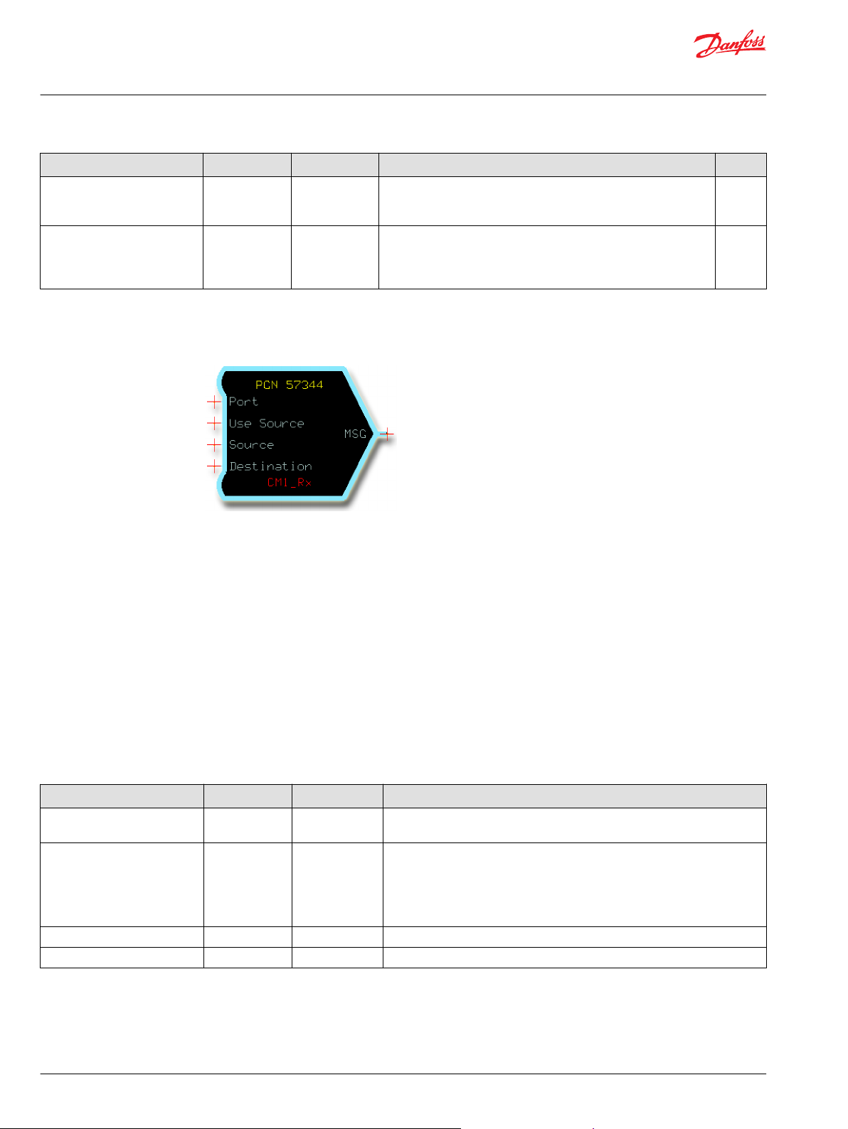
User Manual
PLUS+1® Function Block Library—J1939 Function Blocks
PGN Receivers
Name Type Range Description [Unit] SPN
Status BUS —— The Status bus contains information for each input that is
transmitted in the message.
If the SignalName _NA is true, then that signal is not available.
Fault BUS —— The Fault bus contains information for each input that is transmitted
in the message.
If the SignalName _Flt is true, this indicates a fault condition exists
for this signal.
CM1_Rx—Cab Message 1 Receiver
The CM1_Rx function block receives the CM1 message defined by J1939-DA.
——
——
It provides data signals scaled to application-compatible formats. If data is not available or has an error,
the function block also reports this.
PGN: 57344 (0xE000)
CAN message timeout detection is not included in this function block.
The application can detect this by monitoring the Rx_CM1 signal.
J1939-DA prescribes priorities for SPNs 3695 and 3696. This function block only reports the transmitted
values of these signals and does not enforce priorities.
The CM1 message can be sent to a single node (point-to-point) or all nodes on the CAN bus (broadcast). If
more than one CM1_Rx function block is used in a single PLUS+1® GUIDE application, only the first block
receives and processes the broadcast message.
Inputs The inputs to the CM1_Rx function block are described.
Name Type Range Description
Port Port —— Determines which physical CAN port of the hardware is used to receive the
message.
Use Source BOOL T/F Determines if messages are received from any source or just from the one
specified in Source.
•
T: Only receive this message when transmitted from the address specified by
Source.
•
F: Receive this message from any address.
Source —— 0-253 Address of the transmitting device. Only applies if Use Source is True.
Destination
——
0–255 Address of the receiving device.
28 | © Danfoss | September 2019 11023438 | AQ310885477127en-000101
Page 29

User Manual
PLUS+1® Function Block Library—J1939 Function Blocks
PGN Receivers
Outputs The outputs of the CM1_Rx function block are described.
Name Type Range Description [Unit] SPN
ReqPercntFanSpd U16 0–10000 Requested Percent Fan Speed.
Resolution: 0.4%
[0.01%]
CabInterTmpCmd S32 -27300000–
173496875
AuxlHeatCoolPmpReq U8 0–3 Auxiliary Heater Coolant Pump Request.
BatMainSwHldReq U8 0–3 Battery Main Switch Hold Request.
OperStDirSw BOOL T/F Operator Seat Direction Switch.
StBeltSw BOOL T/F Seat Belt Switch.
PrkBrkCmd U8 0–3 Park Brake Command.
VehLmtSpdGovrnDecSw BOOL T/F Vehicle Limiting Speed Governor Decrement Switch.
VehLmtSpdGovrnIncSw BOOL T/F Vehicle Limiting Speed Governor Increment Switch.
VehLmtSpdGovrnEnSw BOOL T/F Vehicle Limiting Speed Governor Enable Switch.
DslPartFiltRegnInhbtSw BOOL T/F Diesel Particulate Filter Regeneration Inhibit Switch.
DslPartFiltRegnForceSw BOOL T/F Diesel Particulate Filter Regeneration Force Switch.
AutoGrShifEnSw BOOL T/F Automatic Gear Shifting Enable Switch.
EngAutoStartEnSw BOOL T/F Engine Automatic Start Enable Switch.
Cab Interior Temperature Command.
Resolution: 0.03125° C
[0.00001° C]
0: Deactivate water pump.
1: Activate water pump.
2: Reserved.
3: Do not care/take no action.
0: Release Battery Main Switch 1.
1: Hold Battery Main Switch.
2: Undefined.
3: Do not care/take no action.
T: Operator seat facing forward.
F: Operator seat not facing forward.
T: Seat belt buckled.
F: Seat belt not buckled.
0: Park Brake apply not requested.
1: Park Brake apply requested.
2: Reserved.
3: Do not care/take no action.
T: Switch in the on state - decrease.
F: Switch in the off state.
T: Switch in the on state - increase.
F: Switch in the off state.
T: Switch enabled.
F: Switch disabled.
T: Active.
F: Inactive.
T: Active.
F: Inactive.
T: Automated gear shifting enabled.
F: Automated gear shifting disabled.
T: Switch in the on state.
F: Switch in the off state.
986
1691
1684
1682
1714
1856
5630
1655
1654
1653
3695
3696
1666
1656
©
Danfoss | September 2019 11023438 | AQ310885477127en-000101 | 29
Page 30
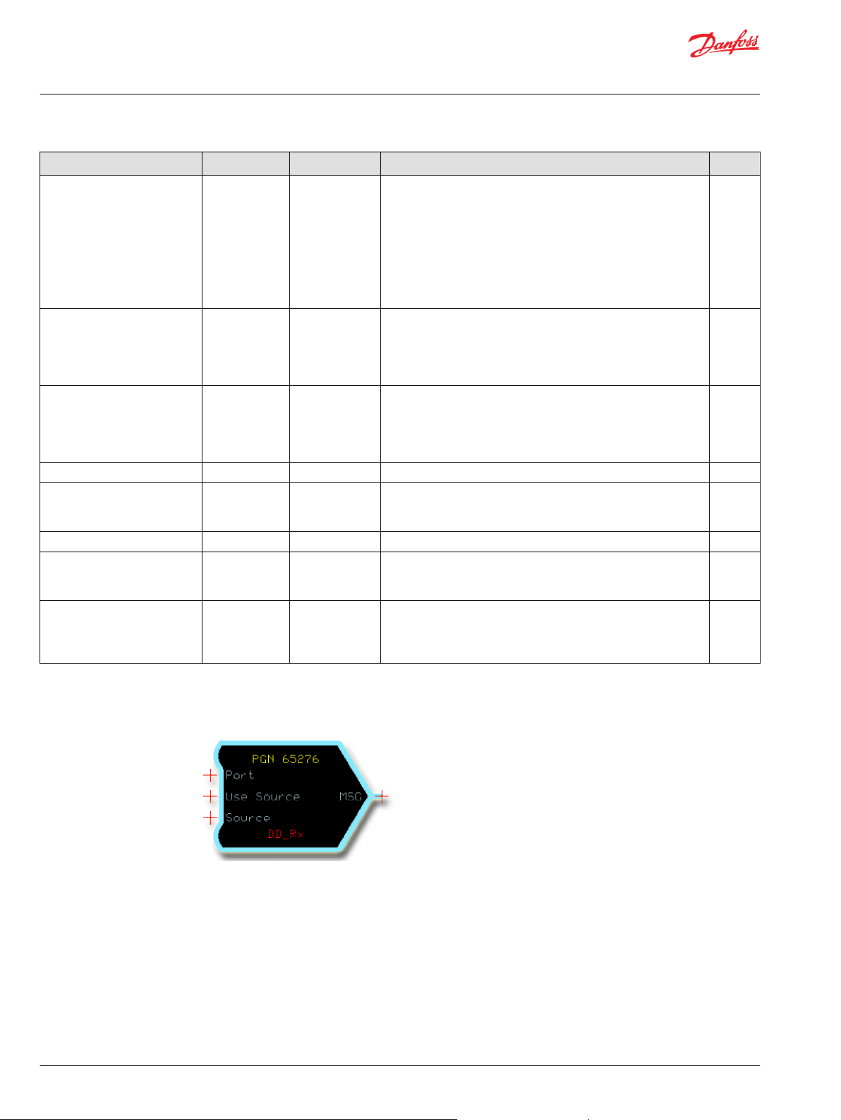
User Manual
PLUS+1® Function Block Library—J1939 Function Blocks
PGN Receivers
Name Type Range Description [Unit] SPN
AuxlHeatModReq U8 0–15 Auxiliary Heater Mode Request.
0: De-activate auxiliary heater.
1: Off due to ADR per European Regulations for Transport of
hazardous materials.
2: Economy mode.
3: Normal mode.
4 -13: Not defined.
14: Reserved.
15: Do not care/take no action.
ReqEngZonHeat U8 0–3 Request Engine Zone Heating.
0: Do not heat engine zone.
1: Heat engine zone.
2: Reserved.
3: Do not care/take no action.
ReqCabZonHeat U8 0–3 Request Cab Zone Heating.
0: Do not heat cab engine zone.
1: Heat cab engine zone.
2: Reserved.
3: Do not care/take no action.
SelctMaxVehSpdLmt U8 0–7 Selected Maximum Vehicle Speed Limit. 2596
Rx_CM1 BOOL T/F True for the first cycle that new data is received.
T: Received new data.
F: Did not receive new data.
CM1_Source U8 0–255 J1939 address of the transmitting device. ——
Status BUS —— The Status bus contains information for each input that is
transmitted in the message.
If the SignalName _NA is true, then that signal is not available.
Fault BUS —— The Fault bus contains information for each input that is
transmitted in the message.
If the SignalName _Flt is true, this indicates a fault condition exists
for this signal.
1683
1685
1686
——
——
——
DD_Rx—Dash Display Receiver
The DD_Rx function block receives the DD message defined by J1939-DA.
It provides data signals scaled to application-compatible formats. If data is not available or has an error,
the function block also reports this.
PGN: 65276 (0xFEFC)
CAN message timeout detection is not included in this function block.
The application can detect this by monitoring the Rx_DD signal.
30 | © Danfoss | September 2019 11023438 | AQ310885477127en-000101
Page 31

User Manual
PLUS+1® Function Block Library—J1939 Function Blocks
PGN Receivers
Inputs The inputs to the DD_Rx function block are described.
Name Type Range Description
Port Port —— Determines which physical CAN port of the hardware is used to receive the
message.
Use Source BOOL T/F Determines if messages are received from any source or just from the one
specified in Source.
•
T: Only receive this message when transmitted from the address specified by
Source.
•
F: Receive this message from any address.
Source —— 0–255 Address of the transmitting device. Only applies if Use Source is True.
Outputs The outputs of the DD_Rx function block are described.
Name Type Range Description [Unit] SPN
WashFluidLev U16 0–10000 Washer Fluid Level.
[0.01%]
FuelLevel U16 0–10000 Fuel Level 1.
[0.01%]
FuelFltDifP U16 0–5000 Engine Fuel Filter Differential Pressure.
[0.1 kPa]
OilFiltDifP U16 0–1250 Engine Oil Filter Differential Pressure.
[0.1 kPa]
CargoAmbTemp S32 -27300000–
173496875
FuelLevel2 U16 0–10000 Fuel Level 1.
Rx_DD BOOL T/F True for the first cycle that new data is received.
Status BUS —— The Status bus contains information for each input that is
Fault BUS —— The Fault bus contains information for each input that is transmitted
Cargo Ambient Temperature.
[0.00001° C]
[0.01%]
T: Received new data.
F: Did not receive new data.
transmitted in the message.
If the SignalName _NA is true, then that signal is not available.
in the message.
If the SignalName _Flt is true, this indicates a fault condition exists
for this signal.
80
96
95
99
169
38
——
——
——
DLCC1_Rx—Direct Lamp Control Command Receiver
The DLCC1_Rx function block receives the direct lamp control command message.
PGN: 64775 (0xFD07)
©
Danfoss | September 2019 11023438 | AQ310885477127en-000101 | 31
Page 32

User Manual
PLUS+1® Function Block Library—J1939 Function Blocks
PGN Receivers
Inputs The inputs to the DLCC1_Rx function block are described.
Name Type Range Description
Port Port —— Determines which physical CAN port of the hardware is used to receive the
message.
Use Source BOOL T/F Determines if messages are received from any source or just from the one
specified in Source.
•
T: Only receive this message when transmitted from the address specified by
Source.
•
F: Receive this message from any address.
Source —— 0-253 Address of the transmitting device. Only applies if Use Source is True.
Outputs The outputs of the DLCC1_Rx function block are described.
Name Type Range Description [Unit] SPN
EngPrtLmpCmd
EngAmbrWrnLmpCmd
EngRedStpLmpCmd
OBDM1fctIndLmpCmd
EngBrkeActLmpCmd
CmprssnBrkEnSwtchIndctrLmpCmd
EngOilPrssrLowLmpCmd
EngClntTmpHghLmpCmd BOOL T/F Command signal directly controlling the Engine Coolant
EngClntLvlLowLmpCmd
BOOL T/F Command signal directly controlling the Engine Protect Lamp.
T: Lamp on.
F: Lamp off.
BOOL T/F Command signal directly controlling the Engine Amber Warning
Lamp.
T: Lamp on.
F: Lamp off.
BOOL T/F Command signal directly controlling the Engine Red Stop Lamp.
T: Lamp on.
F: Lamp off.
BOOL T/F Command signal directly controlling the OBD Malfunction
Indicator Lamp.
T: Lamp on.
F: Lamp off.
BOOL T/F Command signal directly controlling the Engine Brake Active
Lamp, used for engine based retarders.
T: Lamp on.
F: Lamp off.
BOOL T/F Command signal directly controlling Compression Brake Enable
Switch Indicator Lamp.
The compression brake switch indicator signals the status of the
compression brake enable switch to the operator.
T: Lamp on.
F: Lamp off.
BOOL T/F Command signal directly controlling the Engine Oil Pressure Low
Lamp.
T: Lamp on.
F: Lamp off.
Temperature High Lamp.
T: Lamp on.
F: Lamp off.
BOOL T/F Command signal directly controlling the Engine Coolant Level
Low Lamp.
T: Lamp on.
F: Lamp off.
5077
5078
5079
5080
5081
3987
5082
5083
5084
32 | © Danfoss | September 2019 11023438 | AQ310885477127en-000101
Page 33

User Manual
PLUS+1® Function Block Library—J1939 Function Blocks
PGN Receivers
Name Type Range Description [Unit] SPN
EngIdlMngmntActLmpCmd
EngAirFltrRstrctnLampCmd
EngFuelFltrRstrctnLampCmd
EngCntrlMdle1RdyForUseLmpCmd
EngCntrlMdle2RdyForUseLmpCmd
EngCntrlMdle3RdyForUseLmpCmd
EngSpdHghLmpCmd
EngSpdVryHghLmpCmd
VhclAcclrtnRteLmtLmpCmd
Rx_DLCC1
Status BUS —— The Status bus contains information for each input that is
Fault BUS —— The Fault bus contains information for each input that is
BOOL T/F Command signal directly controlling the Engine Idle
Management Active Lamp.
T: Lamp on.
F: Lamp off.
BOOL T/F Command signal controlling the Engine Air Filter Restriction
Lamp.
T: Lamp on.
F: Lamp off.
BOOL T/F Command signal controlling the Engine Fuel Filter Restricted
Lamp.
T: Lamp on.
F: Lamp off.
BOOL T/F Command signal directly controlling the Engine Control Module
1 Ready For Use Lamp.
T: Lamp on.
F: Lamp off.
BOOL T/F Command signal directly controlling the Engine Control Module
2 Ready For Use Lamp.
T: Lamp on.
F: Lamp off.
BOOL T/F Command signal directly controlling the Engine Control Module
3 Ready For Use Lamp.
T: Lamp on.
F: Lamp off.
BOOL T/F Command signal directly controlling the Engine Speed High
Warning Lamp.
T: Lamp on.
F: Lamp off.
BOOL T/F Command signal directly controlling the Engine Speed Very High
Warning Lamp.
T: Lamp on.
F: Lamp off.
BOOL T/F Command signal directly controlling the Vehicle Acceleration
Rate Limit Lamp.
T: Lamp on.
F: Lamp off.
BOOL T/F Indicates that a message has been received
T: New message received.
F: No message received.
transmitted in the message.
If the SignalName_NA is true, then that signal is not available.
transmitted in the message.
If the SignalName_Flt is true, then a fault condition exists for this
signal.
5085
5086
5469
6205
6206
6207
6709
6710
6899
——
——
——
©
Danfoss | September 2019 11023438 | AQ310885477127en-000101 | 33
Page 34

User Manual
PLUS+1® Function Block Library—J1939 Function Blocks
PGN Receivers
DPFC1_Rx—Diesel Particulate Filter Control 1 Receiver
The DPFC1_Rx function block receives the DPFC1 message defined by J1939-DA.
It provides data signals scaled to application-compatible formats. If data is not available or has an error,
the function block also reports this.
PGN: 64892 (0xFD7C)
CAN message timeout detection is not included in this function block.
The application can detect this by monitoring the Rx_DPFC1 signal.
Inputs The inputs to the DPFC1_Rx function block are described.
Name Type Range Description
Port Port —— Determines which physical CAN port of the hardware is used to receive the
message.
Use Source BOOL T/F Determines if messages are received from any source or just from the one
specified in Source.
•
T: Only receive this message when transmitted from the address specified by
Source.
•
F: Receive this message from any address.
Source —— 0–255 Address of the transmitting device. Only applies if Use Source is True.
Outputs The outputs of the DPFC1_Rx function block are described.
Name Type Range Description [Unit] SPN
DPFLampCmd U8 0–6 Diesel Particulate Filter Lamp Command.
0: Off.
1: On – solid.
2: Reserved for SAE assignment.
3: Reserved for SAE assignment.
4: On – fast blink (1 HZ).
5: Reserved for SAE assignment.
6: Reserved for SAE assignment.
DPFPasvRegenStat BOOL T/F Diesel Particulate Filter Passive Regeneration Status.
T: Active.
F: Inactive.
DPFActvRegenStat U8 0–3 Diesel Particulate Filter Active Regeneration Status.
0: Not active.
1: Active.
2: Regeneration needed - automatically initiated active
regeneration imminent.
3697
3699
3700
34 | © Danfoss | September 2019 11023438 | AQ310885477127en-000101
Page 35

User Manual
PLUS+1® Function Block Library—J1939 Function Blocks
PGN Receivers
Name Type Range Description [Unit] SPN
DPFFilterStat U8 0–7 Diesel Particulate Filter Status.
0: Regeneration not needed
1: Regeneration needed - lowest level.
2: Regeneration needed - moderate level.
3: Regeneration needed - highest level.
4: Reserved for SAE assignment.
5: Reserved for SAE assignment.
6: Reserved for SAE assignment.
ActRegenInhStat BOOL T/F Diesel Particulate Filter Active Regeneration Inhibited Status.
T: Inhibited.
F: Not inhibited.
ActRegenInhDueToSw BOOL T/F Diesel Particulate Filter Active Regeneration Inhibited Due to
Inhibit Switch.
T: Inhibited.
F: Not inhibited.
ActRegenInhDueToCltch BOOL T/F Diesel Particulate Filter Active Regeneration Inhibited Due to
Clutch Disengaged.
T: Inhibited.
F: Not inhibited.
ActRegenInhDueToSvcBrk BOOL T/F Diesel Particulate Filter Active Regeneration Inhibited Due to
Service Brake Active.
T: Inhibited.
F: Not inhibited.
ActRegenInhDueToPTO BOOL T/F Diesel Particulate Filter Active Regeneration Inhibited Due to PTO
Active.
T: Inhibited.
F: Not inhibited.
ActRegenInhDueToAcc BOOL T/F Diesel Particulate Filter Active Regeneration Inhibited Due to
Accelerator Pedal Off Idle.
T: Inhibited.
F: Not inhibited.
ActRegenInhDueToNeut BOOL T/F Diesel Particulate Filter Active Regeneration Inhibited Due to Out of
Neutral.
T: Inhibited.
F: Not inhibited.
ActRegenInhDueToSpdAbv BOOL T/F Diesel Particulate Filter Active Regeneration Inhibited Due to
Vehicle Speed Above Allowed Speed.
T: Inhibited.
F: Not inhibited.
ActRegenInhDueToPkBrk BOOL T/F Diesel Particulate Filter Active Regeneration Inhibited Due to
Parking Brake Not Set.
T: Inhibited.
F: Not inhibited.
ActRegenInhDueToLowGasT BOOL T/F Diesel Particulate Filter Active Regeneration Inhibited Due to Low
Exhaust Gas Temperature.
T: Inhibited.
F: Not inhibited.
ActRegenInhDueToSysFlt BOOL T/F Diesel Particulate Filter Active Regeneration Inhibited Due to
System Fault Active.
T: Inhibited.
F: Not inhibited.
ActRegenInhDueToSysTO BOOL T/F Diesel Particulate Filter Active Regeneration Inhibited Due to
System Timeout.
T: Inhibited.
F: Not inhibited.
3701
3702
3703
3704
3705
3706
3707
3708
3709
3710
3711
3712
3713
©
Danfoss | September 2019 11023438 | AQ310885477127en-000101 | 35
Page 36

User Manual
PLUS+1® Function Block Library—J1939 Function Blocks
PGN Receivers
Name Type Range Description [Unit] SPN
ActRegenInhDueToTmpLO BOOL T/F Diesel Particulate Filter Active Regeneration Inhibited Due to
Temporary System Lockout.
T: Inhibited.
F: Not inhibited.
ActRegenInhDueToPrmLO BOOL T/F Diesel Particulate Filter Active Regeneration Inhibited Due to
Permanent System Lockout.
T: Inhibited.
F: Not inhibited.
ActRegenInhDueToEngNotWrm BOOL T/F Diesel Particulate Filter Active Regeneration Inhibited Due to
Engine Not Warmed Up.
T: Inhibited.
F: Not inhibited.
ActRegenInhDueToSpdBel BOOL T/F Diesel Particulate Filter Active Regeneration Inhibited Due to
Vehicle Speed Below Allowed Speed.
T: Inhibited.
F: Not inhibited.
ActRegenInitConfig BOOL T/F Diesel Particulate Filter Automatic Active Regeneration Initiation
Configuration.
T: Enabled.
F: Not enabled.
ExhHighTLampCmd U8 0–7 Exhaust System High Temperature Lamp Command.
0: Off.
1: On – solid.
2: Reserved for SAE assignment.
3: Reserved for SAE assignment.
4: Reserved for SAE assignment.
5: Reserved for SAE assignment.
6: Reserved for SAE assignment.
ActRegenForcedStat U8 0–7 Diesel Particulate Filter Active Regeneration Forced Status.
0: Not active.
1: Active – Forced by Switch. (See SPN 3696).
2: Active – Forced by Service Tool.
3: Reserved for SAE assignment.
4: Reserved for SAE assignment.
5: Reserved for SAE assignment.
6: Reserved for SAE assignment.
HCDPurgEn U8 0–3
ActRegenInhDueToLowExhP
NotMetForActRegen
Rx_DPFC1 BOOL T/F True for the first cycle that new data is received.
BOOL T/F Diesel Particulate Filter Active Regeneration Inhibited Due to Low
BOOL T/F Diesel Particulate Filter 1 Conditions Not Met for Active
Hydrocarbon Doser (HCD) Purging Enable.
0: Purging not enabled.
1: Purging enabled. Less urgent.
2: Purging enabled. Urgent
3: Unavailable.
Exhaust Pressure.
T: Inhibited.
F: Not inhibited.
Regeneration.
T: Inhibited.
F: Not inhibited.
T: Received new data.
F: Did not receive new data.
3714
3715
3716
3717
3718
3698
4175
5504
5629
3750
——
36 | © Danfoss | September 2019 11023438 | AQ310885477127en-000101
Page 37

User Manual
PLUS+1® Function Block Library—J1939 Function Blocks
PGN Receivers
Name Type Range Description [Unit] SPN
Status BUS —— The Status bus contains information for each input that is
transmitted in the message.
If the SignalName _NA is true, then that signal is not available.
Fault BUS —— The Fault bus contains information for each input that is
transmitted in the message.
If the SignalName _Flt is true, this indicates a fault condition exists
for this signal.
EBC1_Rx—Electronic Brake Controller 1 Receiver
The EBC1_Rx function block receives the EBC1 message defined by J1939-DA.
——
——
It provides data signals scaled to application-compatible formats. If data is not available or has an error,
the function block also reports this.
PGN: 61441 (0xF001)
CAN message timeout detection is not included in this function block.
The application can detect this by monitoring the Rx_EBC1 signal.
Inputs The inputs to the EBC1_Rx function block are described.
Name Type Range Description
Port Port —— Determines which physical CAN port of the hardware is used to receive the
message.
Use Source BOOL T/F Determines if messages are received from any source or just from the one
specified in Source.
•
T: Only receive this message when transmitted from the address specified by
Source.
•
F: Receive this message from any address.
Source —— 0-253 Address of the transmitting device. Only applies if Use Source is True.
Outputs The outputs of the EBC_Rx function block are described.
Name Type Range Description [Unit] SPN
ASREngCtrlAct U8 0–2 ASR Engine Control Active:
0: ASR engine control passive but installed.
1: ASR engine control active.
2: Reserved.
ASRBrkCtrlAct U8 0–2 ASR Brake Control Active:
0: ASR brake control passive but installed.
1: ASR brake control active.
2: Reserved.
561
562
©
Danfoss | September 2019 11023438 | AQ310885477127en-000101 | 37
Page 38

User Manual
PLUS+1® Function Block Library—J1939 Function Blocks
PGN Receivers
Name Type Range Description [Unit] SPN
ABSActive U8 0–2 ABS Brake Control Active:
0: ABS passive but installed.
1: ABS active.
2: Reserved.
EBSBrakeSw BOOL T/F EBS Brake Switch.
T: Active.
F: Inactive.
BrakePedalPsn U16 0–10000 Brake Pedal Position.
Resolution: 0.4%
[0.01%]
ABSOffRoadSw BOOL T/F ABS Off-road Switch. 575
ASROffRoadSw BOOL T/F ASR Off-road Switch. 576
ASRHillHoldSw BOOL T/F ASR "Hill Holder" Switch. 577
TracCtrlOvrRdSw BOOL T/F Traction Control Override Switch.
T: Active.
F: Inactive.
AccelInterSw BOOL T/F Accelerator Interlock Switch.
T: Active.
F: Inactive.
EngDerateSw BOOL T/F Engine Derate Switch.
T: Active.
F: Inactive.
EngAuxShutDnSw BOOL T/F Engine Auxiliary Shutdown Switch.
T: Active.
F: Inactive.
RmtAccelEnblSw BOOL T/F Remote Accelerator Enable Switch.
T: Active.
F: Inactive.
EngRetarderSel U16 0–10000 Engine Retarder Selection.
Resolution: 0.4%
[0.01%]
ABSFullOper U8 0–2 ABS Fully Operational:
1: Fully operational.
0: Not fully operational.
2: Reserved.
EBSRedWarnSig U8 0–2 EBS Red Warning Signal:
0: Off.
1: On.
2: Reserved.
EBSABSAmbWarnSig U8 0–2 ABS/EBS Amber Warning Signal (Powered Vehicle):
0: Off.
1: On.
2: Reserved.
ATCASRInfoSig U8 0–2 ATC/ASR Information Signal:
0: Off.
1: On.
2: Reserved.
BrakeCtrlngSA U8 0–253 Source Address of Controlling Device for Brake Control 1481
HaltBrakeSw BOOL T/F Halt brake switch.
T: Active.
F: Inactive.
563
1121
521
1238
972
971
970
969
973
1243
1439
1438
1793
2911
38 | © Danfoss | September 2019 11023438 | AQ310885477127en-000101
Page 39

User Manual
PLUS+1® Function Block Library—J1939 Function Blocks
PGN Receivers
Name Type Range Description [Unit] SPN
TrailABSStat U8 0–2 Trailer ABS Status:
0: Trailer ABS status information available but not active.
1: Trailer ABS active.
2: Reserved.
TrctrMntTrailABSWarnSig U8 0–2 Tractor-Mounted Trailer ABS Warning Signal:
0: Off.
1: On.
2: Reserved.
Rx_EBC1 BOOL T/F True for the first cycle that new data is received.
T: Received new data.
F: Did not receive new data.
Status BUS —— The Status bus contains information for each input that is
transmitted in the message.
If the SignalName _NA is true, then that signal is not available.
Fault BUS —— The Fault bus contains information for each input that is transmitted
in the message.
If the SignalName _Flt is true, this indicates a fault condition exists
for this signal.
1836
1792
——
——
——
EEC1_Rx—Electronic Engine Controller 1 Receiver
The EEC1_Rx function block receives the EEC1 message defined by J1939-DA.
It provides data signals scaled to application-compatible formats. If data is not available or has an error,
the function block also reports this.
PGN: 61444 (0xF004)
CAN message timeout detection is not included in this function block.
The application can detect this by monitoring the Rx_EEC1 signal.
Inputs The inputs to the EEC1_Rx function block are described.
Name Type Range Description
Port Port —— Determines which physical CAN port of the hardware is used to receive the
message.
Use Source BOOL T/F Determines if messages are received from any source or just from the one
specified in Source.
•
T: Only receive this message when transmitted from the address specified by
Source.
•
F: Receive this message from any address.
Source —— 0–255 Address of the transmitting device. Only applies if Use Source is True.
©
Danfoss | September 2019 11023438 | AQ310885477127en-000101 | 39
Page 40

User Manual
PLUS+1® Function Block Library—J1939 Function Blocks
PGN Receivers
Outputs The outputs of the EEC1_Rx function block are described.
Name Type Range Description [Unit] SPN
EngineTorqMode U8 0–15 Engine Torque Mode.
0: Low idle governor/no request (default mode).
1: Accelerator pedal/operator selection.
2: Cruise control.
3: PTO governor.
4: Road speed governor.
5: ASR control.
6: Transmission control.
7: ABS control.
8: Torque limiting.
9: High speed governor.
10: Braking system.
11: Remote accelerator.
12: Service procedure.
13: Not defined.
14: Other.
15: Not available.
ActEnginePctTorq_HiRes U16 0–875 Actual Engine—Percent Torque High Resolution.
Resolution: 0.125%
Note that the resolution of this signal is limited to 0.125%.
[0.001%]
DrvrDmndEngTorq S16 0–12500 Driver's Demand Engine - Percent Torque.
[0.01%]
ActEnginePctTorq S16 0–12500 Actual Engine - Percent Torque.
[0.01%]
EngineSpeed U16 0–8031 Engine Speed.
[RPM]
SrcAddrEngCtrl U8 0–253 Source Address of Controlling Device for Engine Control. 1483
EngStartMode U8 0–12 Engine Starter Mode:
0: Start not requested.
1: Starter active, gear not engaged.
2: Starter active, gear engaged.
3: Start finished; starter not active after having been actively engaged
(after 50ms mode goes to 0000).
4: Starter inhibited due to engine already running.
5: Starter inhibited due to engine not ready for start (preheating).
6: Starter inhibited due to driveline engaged or other transmission
inhibit.
7: Starter inhibited due to active immobilizer.
8: Starter inhibited due to starter over-temp.
9–11: Reserved.
12: Starter inhibited - reason unknown.
EngDemandPctTorq S16 -12500-12500 Engine Demand - Percent Torque.
[0.01%]
Rx_EEC1 BOOL T/F True for the first cycle that new data is received.
T: Received new data.
F: Did not receive new data.
Status BUS —— The Status bus contains information for each input that is
transmitted in the message.
If the SignalName _NA is true, then that signal is not available.
Fault BUS —— The Fault bus contains information for each input that is transmitted
in the message.
If the SignalName _Flt is true, this indicates a fault condition exists
for this signal.
899
4154
512
513
190
1675
2432
——
——
——
40 | © Danfoss | September 2019 11023438 | AQ310885477127en-000101
Page 41

User Manual
PLUS+1® Function Block Library—J1939 Function Blocks
PGN Receivers
EEC2_Rx—Electronic Engine Controller 2 Receiver
The EEC2_Rx function block receives the EEC2 message defined by J1939-DA.
It provides data signals scaled to application-compatible formats. If data is not available or has an error,
the function block also reports this.
PGN: 61443 (0xF003)
CAN message timeout detection is not included in this function block.
The application can detect this by monitoring the Rx_EEC2 signal.
Inputs The inputs to the EEC2_Rx function block are described.
Name Type Range Description
Port Port —— Determines which physical CAN port of the hardware is used to receive the
message.
Use Source BOOL T/F Determines if messages are received from any source or just from the one
specified in Source.
•
T: Only receive this message when transmitted from the address specified by
Source.
•
F: Receive this message from any address.
Source —— 0–255 Address of the transmitting device. Only applies if Use Source is True.
Outputs The outputs of the EEC2_Rx function block are described.
Name Type Range Description [Unit] SPN
AccPed1LowIdleSw BOOL T/F Accelerator Pedal 1 Low Idle Switch.
T: Active.
F: Inactive.
AccPedKickdownSw BOOL T/F Accelerator Pedal Kickdown Switch.
T: Active.
F: Inactive.
RoadSpdLmtStat BOOL T/F Road Speed Limit Status.
T: Inactive.
F: Active.
AccPed2LowIdleSw BOOL T/F Accelerator Pedal 2 Low Idle Switch.
T: Active.
F: Inactive.
AccPed1Psn U16 0–10000 Accelerator Pedal 1 Position.
[0.01%]
EngPctLoadAtSpd U16 0–12500 Engine Percent Load At Current Speed.
[0.01%]
RemoteAccPedalPstn U16 0–10000 Remote Accelerator Pedal Position.
[0.01%]
558
559
1437
2970
91
92
974
©
Danfoss | September 2019 11023438 | AQ310885477127en-000101 | 41
Page 42

User Manual
PLUS+1® Function Block Library—J1939 Function Blocks
PGN Receivers
Name Type Range Description [Unit] SPN
AccPed2Psn U16 0–10000 Accelerator Pedal 2 Position.
[0.01%]
AccRateLmtd BOOL T/F Vehicle Acceleration Rate Limit Status.
T: Active.
F: Inactive.
MmtEngMaxPwrEnFbk U8 0–3 Momentary Engine Maximum Power Enable Feedback:
0: Disabled.
1: Supported.
2: Reserved.
3: Don't care/take no action.
DPFThermMgmtAct U8 0–3 DPF Thermal Management Active:
0: Inactive.
1: Active.
2: Reserved.
3: Don't care/take no action.
SCRThermMgmtAct U8 0–3 SCR Thermal Management Active:
0: Inactive.
1: Active.
2: Reserved.
3: Don't care/take no action.
ActMaxPctTrq U16 0–10000 Actual Maximum Available Engine - Percent Torque.
[0.01%]
EstPumpPctTrq S16 -12500-12500 Estimated Pumping - Percent Torque.
[0.01%]
Rx_EEC2 BOOL T/F True for the first cycle that new data is received.
T: Received new data.
F: Did not receive new data.
Status BUS —— The Status bus contains information for each input that is
transmitted in the message.
If the SignalName _NA is true, then that signal is not available.
Fault BUS —— The Fault bus contains information for each input that is transmitted
in the message.
If the SignalName _Flt is true, this indicates a fault condition exists
for this signal.
29
2979
5021
5399
5400
3357
5398
——
——
——
EEC3_Rx—Electronic Engine Controller 3 Receiver
The EEC3_Rx function block receives the EEC3 message defined by J1939-DA.
It provides data signals scaled to application-compatible formats. If data is not available or has an error,
the function block also reports this.
PGN: 65247 (0xFEDF)
CAN message timeout detection is not included in this function block.
The application can detect this by monitoring the Rx_EEC3 signal.
42 | © Danfoss | September 2019 11023438 | AQ310885477127en-000101
Page 43

User Manual
PLUS+1® Function Block Library—J1939 Function Blocks
PGN Receivers
Inputs The inputs to the EEC3_Rx function block are described.
Name Type Range Description
Port Port —— Determines which physical CAN port of the hardware is used to receive the
message.
Use Source BOOL T/F Determines if messages are received from any source or just from the one
specified in Source.
•
T: Only receive this message when transmitted from the address specified by
Source.
•
F: Receive this message from any address.
Source —— 0–255 Address of the transmitting device. Only applies if Use Source is True.
Outputs The outputs of the EEC3_Rx function block are described.
Name Type Range Description [Unit] SPN
NomFricPctTorq S16 -12500-12500 Nominal Friction - Percent Torque.
[0.01%]
EngDesOpSpd U16 0–8031 Engine's Desired Operating Speed.
[RPM]
DesOpSpdAsAdj U8 0–250 Engine's Desired Operating Speed Asymmetry Adjustment.
Values > 125 indicate preference for higher engine speed if target
speed is not possible while values < 125 indicate preference for lower
engine speed.
ParLossPctTorq S16 -12500-12500 Estimated Engine Parasitic Losses - Percent Torque.
[0.01%]
ExhGasMassFlw U16 0–12851 Aftertreatment 1 Exhaust Gas Mass Flow.
[kg/h]
IntDewPt1 BOOL T/F Aftertreatment 1 Intake Dew Point.
T: Exceeded.
F: Not exceeded.
ExhDewPt1 BOOL T/F Aftertreatment 1 Exhaust Dew Point.
T: Exceeded.
F: Not exceeded.
IntDewPt2 BOOL T/F Aftertreatment 2 Intake Dew Point.
T: Exceeded.
F: Not exceeded.
ExhDewPt2 BOOL T/F Aftertreatment 2 Exhaust Dew Point.
T: Exceeded.
F: Not exceeded.
Rx_EEC3 BOOL T/F True for the first cycle that new data is received.
T: Received new data.
F: Did not receive new data.
Status BUS —— The Status bus contains information for each input that is
transmitted in the message.
If the SignalName _NA is true, then that signal is not available.
Fault BUS —— The Fault bus contains information for each input that is transmitted
in the message.
If the SignalName _Flt is true, this indicates a fault condition exists
for this signal.
514
515
519
2978
3236
3237
3238
3239
3240
——
——
——
©
Danfoss | September 2019 11023438 | AQ310885477127en-000101 | 43
Page 44

User Manual
PLUS+1® Function Block Library—J1939 Function Blocks
PGN Receivers
EFL_P1_Rx—Engine Fluid Level/Pressure 1 Receiver
The EFL_P1_Rx function block receives the EFL/P1 message defined by J1939-DA.
It provides data signals scaled to application-compatible formats. If data is not available or has an error,
the function block also reports this.
PGN: 65263 (0xFEEF)
CAN message timeout detection is not included in this function block.
The application can detect this by monitoring the Rx_EFL_P1signal.
Inputs The inputs to the EFL_P1_Rx function block are described.
Name Type Range Description
Port Port —— Determines which physical CAN port of the hardware is used to receive the
message.
Use Source BOOL T/F Determines if messages are received from any source or just from the one
specified in Source.
•
T: Only receive this message when transmitted from the address specified by
Source.
•
F: Receive this message from any address.
Source —— 0–255 Address of the transmitting device. Only applies if Use Source is True.
Outputs The outputs of the EFL_P1_Rx function block are described.
Name Type Range Description [Unit] SPN
EngFuelDvryPress U16 0–1000 Engine Fuel Delivery Pressure.
[kPa]
EngExtCrnkBlwPr U16 0–1250 Engine Extended Crankcase Blow-by Pressure.
[0.01 kPa]
EngineOilLevel U16 0–10000 Engine Oil Level.
[0.01%]
EngineOilPress U16 0–1000 Engine Oil Pressure.
[kPa]
EngCrnkcasePress S16 -25000–25199 Engine Crankcase Pressure.
[0.01 kPa]
CoolantPressure U16 0–500 Engine Coolant Pressure.
[kPa]
EngCoolantLevel U16 0–10000 Engine Coolant Level.
[0.01%]
Rx_EFL_P1 BOOL T/F True for the first cycle that new data is received.
T: Received new data.
F: Did not receive new data.
94
22
98
100
101
109
111
——
44 | © Danfoss | September 2019 11023438 | AQ310885477127en-000101
Page 45

User Manual
PLUS+1® Function Block Library—J1939 Function Blocks
PGN Receivers
Name Type Range Description [Unit] SPN
Status BUS —— The Status bus contains information for each input that is
transmitted in the message.
If the SignalName _NA is true, then that signal is not available.
Fault BUS —— The Fault bus contains information for each input that is transmitted
in the message.
If the SignalName _Flt is true, this indicates a fault condition exists
for this signal.
EFL_P2_Rx—Engine Fluid Level/Pressure 2 Receiver
The EFL_P2_Rx function block receives the EFL/P2 message defined by J1939-DA.
——
——
It provides data signals scaled to application-compatible formats. If data is not available or has an error,
the function block also reports this.
PGN: 65243 (0xFEDB)
CAN message timeout detection is not included in this function block.
The application can detect this by monitoring the Rx_EFL_P2 signal.
Inputs The inputs to the EFL_P2_Rx function block are described.
Name Type Range Description
Port Port —— Determines which physical CAN port of the hardware is used to receive the
message.
Use Source BOOL T/F Determines if messages are received from any source or just from the one
specified in Source.
•
T: Only receive this message when transmitted from the address specified by
Source.
•
F: Receive this message from any address.
Source —— 0–255 Address of the transmitting device. Only applies if Use Source is True.
Outputs The outputs of the EFL_P2_Rx function block are described.
Name Type Range Description [Unit] SPN
EngInjCtrlP U32 0–250996 Engine Injection Control Pressure.
[0.001 MPa]
InjMetRail1P U32 0–250996 Engine Injector Metering Rail 1 Pressure.
[0.001 MPa]
InjTmRail1P U32 0–250996 Engine Injector Timing Rail 1 Pressure.
[0.001 MPa]
InjMetRail2P U32 0–250996 Engine Injector Metering Rail 2 Pressure.
[0.001 MPa]
164
157
156
1349
©
Danfoss | September 2019 11023438 | AQ310885477127en-000101 | 45
Page 46

User Manual
PLUS+1® Function Block Library—J1939 Function Blocks
PGN Receivers
Name Type Range Description [Unit] SPN
Rx_EFL_P2 BOOL T/F True for the first cycle that new data is received.
T: Received new data.
F: Did not receive new data.
Status BUS —— The Status bus contains information for each input that is
transmitted in the message.
If the SignalName _NA is true, then that signal is not available.
Fault BUS —— The Fault bus contains information for each input that is transmitted
in the message.
If the SignalName _Flt is true, this indicates a fault condition exists
for this signal.
EJM_Rx—Extended Joystick Message Receiver
The EJM_Rx function block receives the EJM message for messages 1-10.
——
——
——
Inputs The inputs to the EJM_Rx function block are described.
Name Type Range Description
Port Port —— Determines which physical CAN port of the hardware is used to receive the
message.
Use Source BOOL T/F Determines if messages are received from any source or just from the one
specified in Source.
•
T: Only receive this message when transmitted from the address specified by
Source.
•
F: Receive this message from any address.
Source —— 0-253 Address of the transmitting device. Only applies if Use Source is True.
Msg_Num U8 1-10 Messages are received for this EJM number.
Protected BOOL T/F Save the first message or save the last message.
T: Save the first message received in the loop.
F: Save the last message received in the loop.
Time Out U16 0-10000 Maximum time between messages before a timeout fault is triggered.
[ms]
46 | © Danfoss | September 2019 11023438 | AQ310885477127en-000101
Page 47

User Manual
PLUS+1® Function Block Library—J1939 Function Blocks
PGN Receivers
Outputs The outputs of the EJM_Rx function block are described.
Name Type Range Description [Unit]
Status BUS —— The Status bus contains information for each input that is transmitted in
the message.
If the SignalName_NA is true, then that signal is not available.
XGrp/YGrp/T/ XGrp_Det/
YGrp_Det/T_Det _NA
Fault BUS —— The Fault bus contains information for each input that is transmitted in
XGrp/YGrp/T/ XGrp_Det/
YGrp_Det/T_Det _Flt
Timeout_EJM BOOL T/F T: Message timed out.
NoMsgReceived_EJM BOOL T/F T: No message received since power on.
XGrp_Psn S16 -10000-10000 X Proportional Grip Switch Position.
YGrp_Psn S16 -10000-10000 Y Proportional Grip Switch Position.
T_Axis_Psn S16 -10000-10000 Theta Axis Position.
XGrp_Det BOOL T/F X Proportional Grip Detent Switch.
YGrp_Det BOOL T/F Y Proportional Grip Detent Switch.
T_Axis_Det BOOL T/F Theta Axis Detent Switch.
Rx_EJM BOOL T/F Pulses TRUE for one loop when new data is available.
Status
BUS —— Indicates if the signal is not configured/not enabled.
T: Signal X is not enabled/not configured.
F: Signal X is enabled/configured.
the message.
If the SignalName_Flt is true, then a fault condition exists for this signal.
BOOL T/F T: Signal X is faulted.
F: Signal X is OK.
F: Message is OK.
F: A message has been received since power on.
[0.01%]
[0.01%]
[0.01%]
T: Active.
F: Not active.
T: Active.
F: Not active.
T: Active.
F: Not active.
T: Received new data.
F: Did not receive new data.
U16 —— Bitwise code where multiple items can be reported at a time.
0x0000: Status OK.
0x8008: At least one parameter is out of range
EJM1_Rx—Extended Joystick Message 1 Receiver
The EJM1_Rx function block receives the EJM1 message defined by J1939-DA.
It provides data signals scaled to application-compatible formats. If data is not available or has an error,
the function block also reports this.
©
Danfoss | September 2019 11023438 | AQ310885477127en-000101 | 47
Page 48

User Manual
PLUS+1® Function Block Library—J1939 Function Blocks
PGN Receivers
PGN: 64983 (0xFDD7)
CAN message timeout detection is included in this function block.
This block reports all signals as Not Available previous to receiving data from the joystick when the
application starts.
Inputs The inputs to the BJM1_Rx function block are described.
Name Type Range Description
Port Port —— Determines which physical CAN port of the hardware is used to receive the
message.
Use Source BOOL T/F Determines if messages are received from any source or just from the one
specified in Source.
•
T: Only receive this message when transmitted from the address specified by
Source.
•
F: Receive this message from any address.
Source —— 0–255 Address of the transmitting device. Only applies if Use Source is True.
Time Out
U16
0–65535 The Time Out parameter is located on the inside of this function block.
If this function block receives no message within the time set by this
parameter, it:
Sets all its Fault signals to true.
•
Then holds these Fault signals true until it receives another message.
•
Outputs The outputs of the EJM1_Rx function block are described.
Name Type Range Description [Unit] SPN
JS1_XGrp_Psn S16 -10000-10000 Joystick 1 Grip X-Axis Position
[0.01%]
JS1_YGrp_Psn S16 -10000-10000 Joystick 1 Grip Y-Axis Position
[0.01%]
JS1_T_Axis_Psn S16 -10000-10000 Joystick 1 Theta-Axis Position
[0.01%]
JS1_XGrp_Det BOOL T/F Joystick 1 Grip X-Detent Position Status.
T: Active.
F: Inactive.
JS1_YGrp_Det BOOL T/F Joystick 1 Grip Y-Detent Position Status.
T: Active.
F: Inactive.
JS1_T_Axis_Det BOOL T/F Joystick 1 Theta-Detent Position Status.
T: Active.
F: Inactive.
Rx_EJM1 BOOL T/F True for the first cycle that new data is received.
T: Received new data.
F: Did not receive new data.
Status BUS —— The Status bus contains information for each input that is
transmitted in the message.
If the SignalName _NA is true, then that signal is not available.
Fault BUS —— The Fault bus contains information for each input that is transmitted
in the message.
If the SignalName _Flt is true, this indicates a fault condition exists
for this signal.
2662
2663
2664
2682
2683
2684
——
——
——
48 | © Danfoss | September 2019 11023438 | AQ310885477127en-000101
Page 49

User Manual
PLUS+1® Function Block Library—J1939 Function Blocks
PGN Receivers
EJM2_Rx—Extended Joystick Message 2 Receiver
The EJM2_Rx function block receives the EJM2 message defined by J1939-DA.
It provides data signals scaled to application-compatible formats. If data is not available or has an error,
the function block also reports this.
PGN: 64985 (0xFDD9)
CAN message timeout detection is included in this function block.
This block reports all signals as Not Available previous to receiving data from the joystick when the
application starts.
Inputs The inputs to the BJM1_Rx function block are described.
Name Type Range Description
Port Port —— Determines which physical CAN port of the hardware is used to receive the
message.
Use Source BOOL T/F Determines if messages are received from any source or just from the one
specified in Source.
•
T: Only receive this message when transmitted from the address specified by
Source.
•
F: Receive this message from any address.
Source —— 0–255 Address of the transmitting device. Only applies if Use Source is True.
Time Out
U16
0–65535 The Time Out parameter is located on the inside of this function block.
If this function block receives no message within the time set by this
parameter, it:
Sets all its Fault signals to true.
•
Then holds these Fault signals true until it receives another message.
•
Outputs The outputs of the EJM2_Rx function block are described.
Name Type Range Description [Unit] SPN
JS2_XGrp_Psn S16 -10000-10000 Joystick 2 Grip X-Axis Position
[0.01%]
JS2_YGrp_Psn S16 -10000-10000 Joystick 2 Grip Y-Axis Position.
[0.01%]
JS2_T_Axis_Psn S16 -10000-10000 Joystick 2 Theta-Axis Position.
[0.01%]
JS2_XGrp_Det BOOL T/F Joystick 2 Grip X-Detent Position Status.
T: Active.
F: Inactive.
JS2_YGrp_Det BOOL T/F Joystick 2 Grip Y-Detent Position Status.
T: Active.
F: Inactive.
2699
2700
2701
2719
2720
©
Danfoss | September 2019 11023438 | AQ310885477127en-000101 | 49
Page 50

User Manual
PLUS+1® Function Block Library—J1939 Function Blocks
PGN Receivers
Name Type Range Description [Unit] SPN
JS2_T_Axis_Det BOOL T/F Joystick 2 Theta-Detent Position Status.
T: Active.
F: Inactive.
Rx_EJM2 BOOL T/F True for the first cycle that new data is received.
T: Received new data.
F: Did not receive new data.
Status BUS —— The Status bus contains information for each input that is
transmitted in the message.
If the SignalName _NA is true, then that signal is not available.
Fault BUS —— The Fault bus contains information for each input that is transmitted
in the message.
If the SignalName _Flt is true, this indicates a fault condition exists
for this signal.
EOI_Rx—Engine Operating Information Receiver
The EOI_Rx function block receives the EOI message defined by J1939-DA.
2721
——
——
——
PGN: 64914 (0xFD92)
Inputs The inputs to the EOI_Rx function block are described.
Name Type Range Description
Port Port —— Determines which physical CAN port of the hardware is used to receive the
message.
Use Source BOOL T/F Determines if messages are received from any source or just from the one
specified in Source.
•
T: Only receive this message when transmitted from the address specified by
Source.
•
F: Receive this message from any address.
Source —— 0-253 Address of the transmitting device. Only applies if Use Source is True.
50 | © Danfoss | September 2019 11023438 | AQ310885477127en-000101
Page 51

User Manual
PLUS+1® Function Block Library—J1939 Function Blocks
PGN Receivers
Outputs The outputs of the EOI_Rx function block are described.
Name Type Range Description [Unit] SPN
EngOpState
FuelPumpPrimerCtrl
EngStarterMtrRelayCtrl
TmRemain_EngOpState
EngFuelShutoffVentCtrl
EngFuelShutoff1Ctrl
EngFuelShutoff2Ctrl
EngFuelShutoffVLTC
EngOilPrimePumpCtrl
EngOilPrimePreHeatCtrl
U8 0-7 Engine Operating State.
0: Engine stopped.
1: Pre-start.
2: Starting.
3: Warm-up.
4: Running.
5: Cool-down.
6: Engine stopping.
7: Post-run.
U8 0-3 Fuel Pump Primer Control.
Activates or deactivates a priming system on the fuel transfer system.
0: Deactivate.
1: Activate.
2: Reserved.
3: Unavailable.
U8 0-3 Engine Starter Motor Relay Control.
Indicates if the engine starter motor relay is activated.
0: Off.
1: On.
2: Reserved.
3: Don't care/take no action.
U16 0-64255 Time Remaining in Engine Operating State.
[second]
U8 0-3 Engine Fuel Shutoff Vent Control.
0: Vent closed.
1: Vent open.
2: Reserved.
3: Don't care/take no action.
U8 0-3 Engine Fuel Shutoff 1 Control.
0: Open.
1: Closed.
2: Reserved.
3: Don't care/take no action.
U8 0-3 Engine Fuel Shutoff 2 Control.
0: Open.
1: Closed.
2: Reserved.
3: Don't care/take no action.
U8 0-3 Engine Fuel Shutoff Valve Leak Test Control.
0: Off.
1: On.
2: Reserved.
3: Don't care/take no action.
U8 0-3 Engine Oil Priming Pump Control.
0: Off.
1: On.
2: Reserved.
3: Unavailable.
U8 0-3 Engine Oil Pre-Heater Control.
0: Off.
1: On.
2: Reserved.
3: Don't care/take no action.
3543
4082
6385
3544
3608
632
2807
3601
3589
3602
©
Danfoss | September 2019 11023438 | AQ310885477127en-000101 | 51
Page 52

User Manual
PLUS+1® Function Block Library—J1939 Function Blocks
PGN Receivers
Name Type Range Description [Unit] SPN
EngElecSysPwrConservCtrl
EngPreHeatCtrl
EngCoolPumpCtrl
EngEmcyShutdownRqst
EngEmcyShutdownInd
EngColdAmbElevIdleStat
EngDesiredTorqRqst
EngDerateRqst
Rx_EOI
Status BUS —— The Status bus contains information for each input that is
Fault BUS —— The Fault bus contains information for each input that is transmitted
U8 0-3 Engine Electrical System Power Conservation Control.
0: Off.
1: On.
2: Reserved.
3: Unavailable.
U8 0-3 Engine Pre-Heater Control.
0: Off.
1: On.
2: Reserved.
3: Unavailable.
U8 0-3 Engine Coolant Pump Control.
0: Off.
1: On.
2: Reserved.
3: Don't care/take no action.
U8 0-3 Engine Controlled Shutdown Request.
0: Off.
1: On.
2: Reserved.
3: Don't care/take no action.
U8 0-3 Engine Emergency Shutdown Indication. A signal that the engine is
shutting down immediately.
0: Off.
1: On.
2: Reserved.
3: Don't care/take no action.
U8 0-3 Engine Cold Ambient Elevated Idle Status.
0: No Idle Elevation Active - standard idle speed
1: Idle Elevation Active
2: Reserved.
3: Unavailable.
S16 0-12500 Engine Desired Torque Request.
[0.01%]
U16 0-10000 Engine Derate Request.
[0.01%]
BOOL T/F True for the first cycle that new data is received.
T: Received new data.
F: Did not receive new data.
transmitted in the message.
If the SignalName_NA is true, then that signal is not available.
in the message.
If the SignalName_Flt is true, then a fault condition exists for this
signal.
3603
3604
3605
3606
3607
6884
6807
3644
——
——
——
ERC1_Rx—Engine Retarder Control Receiver
The ERC1_Rx function block receives the Engine Retarder Control message.
It is used by several types of retarding devices, such as engine compression release brakes, exhaust
system restriction brakes, and driveline retarders using hydraulic, electric, or mechanical friction to slow
the vehicle.
52 | © Danfoss | September 2019 11023438 | AQ310885477127en-000101
Page 53

User Manual
PLUS+1® Function Block Library—J1939 Function Blocks
PGN Receivers
PGN: 61440 (0xF000)
Inputs The inputs to the ERC1_Rx function block are described.
Name Type Range Description
Port Port —— Determines which physical CAN port of the hardware is used to receive the
message.
Use Source BOOL T/F Determines if messages are received from any source or just from the one
specified in Source.
•
T: Only receive this message when transmitted from the address specified by
Source.
•
F: Receive this message from any address.
Source —— 0-253 Address of the transmitting device. Only applies if Use Source is True.
Outputs The outputs of the ERC1_Rx function block are described.
Name Type Range Description [Unit] SPN
Status BUS —— The Status bus contains information for each input that is
transmitted in the message.
If the SignalName_NA is true, then that signal is not available.
Fault BUS —— The Fault bus contains information for each input that is transmitted
in the message.
If the SignalName_Flt is true, then a fault condition exists for this
signal.
RtdrTorqMode
RtdrEn_BrkAstSw
RtdrEn_ShftAstSw
ActRtdr_PctTorq
U8 0-15 Retarder Torque Mode.
Indicates which retarder torque mode is currently generating,
limiting, or controlling the torque.
0: No braking.
1-15: A torque request or the identified function is controlling the
retarder.
BOOL T/F Retarder Enable Brake Assist Switch.
Indicates whether the retarder is enabled for braking assist.
T: Brake assist enabled.
F: Brake assist disabled.
BOOL T/F Retarder Enable Shift Assist Switch.
Indicates if the retarder is enabled for transmission shift assist.
T: Shift assist enabled. The transmission can activate the retarder.
F: Shift assist disabled.
S16 -12500-0 Actual Retarder Percent Torque.
Actual braking torque of the retarder as a percent of retarder
configuration.
[0.01%]
——
——
900
571
572
520
©
Danfoss | September 2019 11023438 | AQ310885477127en-000101 | 53
Page 54

User Manual
PLUS+1® Function Block Library—J1939 Function Blocks
PGN Receivers
Name Type Range Description [Unit] SPN
IntdedRtdr_Pct_Torq
EngCoolantLoadInc
RtdrRqstBrkLght
RtdrRoadSpdLmtSw
RtdrRoadSpdExcdStat
ScrAddrCtrlDevRtdr
DriversDemandRtdr_PctTorq
RtdrSelection_NonEng
ActMaxAvailRtdr_PctTorq
Rx_ERC1
Status U16 —— Bitwise code where multiple items can be reported at a time.
S16 -12500-0 Intended Retarder Percent Torque.
Braking torque of retarder that the retarder is currently trying to
achieve.
[0.01%]
BOOL T/F Engine Coolant Load Increase Status.
Status of an event, external to the engine, that may increase the
nominal temperature of the engine coolant liquid.
T: Coolant load increase possible.
F: No coolant load increase.
U8 0-3 Retarder Requesting Brake Light.
Indicates whether the retarder is requesting that the brake lights
illuminate.
0: No request for brake lights to illuminate.
1: Request for brake lights to illuminate.
2: Reserved.
3: Don't care/take no action.
BOOL T/F Retarder Road Speed Limit Switch.
T: Road speed limiting by retarder is enabled.
F: Road speed limiting by retarder is disabled.
U8 0-3 Retarder Road Speed Exceeded Status.
0: Road speed is below threshold.
1: Road speed is above threshold, retarder can be activated.
U8 0-253 Address of the device controlling the retarder. 1480
S16 -12500-0 Drivers demand retarder, percent torque. The maximum torque
selected by the driver when one or more modes are selected.
[0.01%]
U16 0-10000 Retarder selection, non-engine. The position of the driver’s selector
for retarders that are not part of the engine system, expressed as
percent and determined by the ratio of current position to the
maximum possible position.
[0.01%]
S16 -12500-0 Actual maximum available retarder percent torque. The maximum
amount of torque that the retarder can immediately deliver.
[0.01%]
BOOL T/F Indicates whether new electronic retarder controller 1 is received.
True for the first cycle that new data is received.
T: Received new data.
F: Did not receive new data.
0x0000: Status OK.
0x8008: At least one parameter is out of range.
1085
1082
1667
4233
4234
1715
1716
1717
3606
——
ET1_Rx—Engine Temperature 1 Receiver
The ET1_Rx function block receives the ET1 message defined by J1939-DA.
It provides data signals scaled to application-compatible formats. If data is not available or has an error,
the function block also reports this.
54 | © Danfoss | September 2019 11023438 | AQ310885477127en-000101
Page 55

User Manual
PLUS+1® Function Block Library—J1939 Function Blocks
PGN Receivers
CAN message timeout detection is not included in this function block.
The application can detect this by monitoring the Rx_ET1 signal.
PGN: 65262 (0xFEEE)
Inputs The inputs to the ET1_Rx function block are described.
Name Type Range Description
Port Port —— Determines which physical CAN port of the hardware is used to receive the
message.
Use Source BOOL T/F Determines if messages are received from any source or just from the one
specified in Source.
•
T: Only receive this message when transmitted from the address specified by
Source.
•
F: Receive this message from any address.
Source —— 0–255 Address of the transmitting device. Only applies if Use Source is True.
Outputs The outputs of the ET1_Rx function block are described.
Name Type Range Description [Unit] SPN
EngCoolantTemp S16 -40–210 Engine Coolant Temperature
[° C]
EngineFuelTemp1 S16 -40–210 Engine Fuel Temperature 1
[° C]
EngineOilTemp1 S32 -27300000–
173496875
EngTurboOilTemp S32 -27300000–
173496875
EngIntcoolTemp S16 -40–210 Engine Intercooler Temperature
EngIntcoolTherm U16 0–10000 Engine Intercooler Thermostat Opening
Rx_ET1 BOOL T/F True for the first cycle that new data is received.
Status BUS —— The Status bus contains information for each input that is
Fault BUS —— The Fault bus contains information for each input that is transmitted
Engine Oil Temperature 1
[0.00001° C]
Engine Turbocharger Oil Temperature
[0.00001° C]
[° C]
[0.01%]
T: Received new data.
F: Did not receive new data.
transmitted in the message.
If the SignalName _NA is true, then that signal is not available.
in the message.
If the SignalName _Flt is true, this indicates a fault condition exists
for this signal.
110
174
175
176
52
1134
——
——
——
©
Danfoss | September 2019 11023438 | AQ310885477127en-000101 | 55
Page 56

User Manual
PLUS+1® Function Block Library—J1939 Function Blocks
PGN Receivers
ET2_Rx—Engine Temperature 2 Receiver
The ET2_Rx function block receives the ET2 message defined by J1939-DA.
It provides data signals scaled to application-compatible formats. If data is not available or has an error,
the function block also reports this.
PGN: 65188 (0xFEA4)
CAN message timeout detection is not included in this function block.
The application can detect this by monitoring the Rx_ET2 signal.
Inputs The inputs to the ET2_Rx function block are described.
Name Type Range Description
Port Port —— Determines which physical CAN port of the hardware is used to receive the
message.
Use Source BOOL T/F Determines if messages are received from any source or just from the one
specified in Source.
•
T: Only receive this message when transmitted from the address specified by
Source.
•
F: Receive this message from any address.
Source —— 0–255 Address of the transmitting device. Only applies if Use Source is True.
Outputs The outputs of the ET2_Rx function block are described.
Name Type Range Description [Unit] SPN
EngOilTemp2 S32 -27300000–
173496875
EngECUTemp S32 -27300000–
173496875
EngEGR1DiffP S32 -25000–25199 Engine Exhaust Gas Recirculation 1 Differential Pressure.
EngEGR1Temp S32 -27300000–
173496875
Rx_ET2 BOOL T/F True for the first cycle that new data is received.
Status BUS —— The Status bus contains information for each input that is
Fault BUS —— The Fault bus contains information for each input that is transmitted
Engine Oil Temperature 2.
[0.00001° C]
Engine ECU Temperature.
[0.00001° C]
[0.01 kPa]
Engine Exhaust Gas Recirculation 1 Temperature.
[0.00001° C]
T: Received new data.
F: Did not receive new data.
transmitted in the message.
If the SignalName _NA is true, then that signal is not available.
in the message.
If the SignalName _Flt is true, this indicates a fault condition exists
for this signal.
1135
1136
411
412
——
——
——
56 | © Danfoss | September 2019 11023438 | AQ310885477127en-000101
Page 57

User Manual
PLUS+1® Function Block Library—J1939 Function Blocks
PGN Receivers
ET3_Rx—Engine Temperature 3 Receiver
The ET3_Rx function block receives the ET3 message defined by J1939-DA.
It provides data signals scaled to application-compatible formats. If data is not available or has an error,
the function block also reports this.
PGN: 65129 (0xFE69)
The application can detect this by monitoring the Rx_ET3 signal.
Inputs The inputs to the ET3_Rx function block are described.
Name Type Range Description
Port Port —— Determines which physical CAN port of the hardware is used to receive the
message.
Use Source BOOL T/F Determines if messages are received from any source or just from the one
specified in Source.
•
T: Only receive this message when transmitted from the address specified by
Source.
•
F: Receive this message from any address.
Source —— 0–255 Address of the transmitting device. Only applies if Use Source is True.
Outputs The outputs of the ET3_Rx function block are described.
Name Type Range Description [Unit] SPN
EngIntMan1AirTempHR S32 -27300000–
173496875
EngCoolTempHR S32 -27300000–
173496875
EngInVlvActSysOilT S32 -27300000–
173496875
EngChrgAirCool1OutT S32 -27300000–
173496875
Rx_ET3 BOOL T/F True for the first cycle that new data is received.
Status BUS —— The Status bus contains information for each input that is
Fault BUS —— The Fault bus contains information for each input that is transmitted
Engine Intake Manifold 1 Air Temperature (High Resolution).
[0.00001° C]
Engine Coolant Temperature (High Resolution).
[0.00001° C]
Engine Intake Valve Actuation System Oil Temperature.
[0.00001° C]
Engine Charge Air Cooler 1 Outlet Temperature.
[0.00001° C]
T: Received new data.
F: Did not receive new data.
transmitted in the message.
If the SignalName _NA is true, then that signal is not available.
in the message.
If the SignalName _Flt is true, this indicates a fault condition exists
for this signal.
1636
1637
2986
2630
——
——
——
©
Danfoss | September 2019 11023438 | AQ310885477127en-000101 | 57
Page 58

User Manual
PLUS+1® Function Block Library—J1939 Function Blocks
PGN Receivers
ETC1_Rx—Electronic Transmission Controller 1 Receiver
The ETC1_Rx function block receives the ETC1 message defined by J1939-DA.
It provides data signals scaled to application-compatible formats. If data is not available or has an error,
the function block also reports this.
PGN: 61442 (0xF002)
CAN message timeout detection is not included in this function block.
The application can detect this by monitoring the Rx_ETC1 signal.
Inputs The inputs to the ETC1_Rx function block are described.
Name Type Range Description
Port Port —— Determines which physical CAN port of the hardware is used to receive the
message.
Use Source BOOL T/F Determines if messages are received from any source or just from the one
specified in Source.
•
T: Only receive this message when transmitted from the address specified by
Source.
•
F: Receive this message from any address.
Source —— 0–255 Address of the transmitting device. Only applies if Use Source is True.
Outputs The outputs of the ETC1_Rx function block are described.
Name Type Range Description [Unit] SPN
EngMmtOvEnbl BOOL T/F Engine Momentary Overspeed Enable.
T: Momentary engine overspeed enabled.
F: Momentary engine overspeed disabled.
PctCltchSlip U16 0–10000 Percent Clutch Slip.
[0.01%]
PrgShftDisbl BOOL T/F Progressive Shift Disable.
T: Progressive shift disabled.
F: Progressive shift is not disabled.
SrcAdrTrnCtr U8 0–253 Source Address of Controlling Device for Transmission Control. 1482
TrnDrvEngage BOOL T/F Transmission Driveline Engaged.
T: Driveline engaged.
F: Driveline disengaged.
TrnInShfSpd U32 0–80318 Transmission Input Shaft Speed.
[0.1 RPM]
TrnInShfSpd_HiRes U32 0–8031875 High Resolution Transmission Input Shaft Speed.
[0.001 RPM]
TrnOutShfSpd U32 0–80318 Transmission Output Shaft Speed.
[0.1 RPM]
606
522
607
560
161
161
191
58 | © Danfoss | September 2019 11023438 | AQ310885477127en-000101
Page 59

User Manual
PLUS+1® Function Block Library—J1939 Function Blocks
PGN Receivers
Name Type Range Description [Unit] SPN
TrnOutShfSpd_HiRes U32 0–8031875 High Resolution Transmission Output Shaft Speed.
[0.001 RPM]
TrnShftPrcss BOOL T/F Transmission Shift In Process.
T: Shift in process.
F: Shift not in process.
TrnTrqCnvLck BOOL T/F Transmission Torque Converter Lockup Engaged.
T: Torque converter lockup engaged.
F: Torque converter lockup disengaged.
TrnTrqCnvLckTrsInPrs BOOL T/F Transmission Torque Converter Lockup Transition in Process.
T: Transition is in process.
F: Transition is not in process.
MmtEngMaxPwr BOOL T/F Momentary Engine Maximum Power Enable.
T: Momentarily requesting maximum power available.
F: Not requesting maximum power available.
Rx_ETC1 BOOL T/F True for the first cycle that new data is received.
T: Received new data.
F: Did not receive new data.
Status BUS —— The Status bus contains information for each input that is
transmitted in the message.
If the SignalName _NA is true, then that signal is not available.
Fault BUS —— The Fault bus contains information for each input that is transmitted
in the message.
If the SignalName _Flt is true, this indicates a fault condition exists
for this signal.
191
574
573
4816
5015
——
——
——
ETC2_Rx—Electronic Transmission Controller 2 Receiver
The ETC2_Rx function block receives the ETC2 message defined by J1939-DA.
It provides data signals scaled to application-compatible formats. If data is not available or has an error,
the function block also reports this.
PGN: 61445 (0xF005)
CAN message timeout detection is not included in this function block.
The application can detect this by monitoring the Rx_ETC2 signal.
©
Danfoss | September 2019 11023438 | AQ310885477127en-000101 | 59
Page 60

User Manual
PLUS+1® Function Block Library—J1939 Function Blocks
PGN Receivers
Inputs The inputs to the ETC2_Rx function block are described.
Name Type Range Description
Port Port —— Determines which physical CAN port of the hardware is used to receive the
message.
Use Source BOOL T/F Determines if messages are received from any source or just from the one
specified in Source.
•
T: Only receive this message when transmitted from the address specified by
Source.
•
F: Receive this message from any address.
Source —— 0–255 Address of the transmitting device. Only applies if Use Source is True.
Outputs The outputs of the ETC2_Rx function block are described.
Name Type Range Description [Unit] SPN
TransCurRngCharA U8 0-255 Transmission Current Range, First Character.
[ASCII]
TransCurRngCharB U8 0-255 Transmission Current Range, Second Character.
[ASCII]
TransReqRngCharA U8 0-255 Transmission Requested Range, First Character.
[ASCII]
TransReqRngCharB U8 0-255 Transmission Requested Range, Second Character.
[ASCII]
TransSelGear S16 -125-125 Transmission Selected Gear.
251: Park
TrnActGearRt U16 64255 Transmission Actual Gear Ratio.
[0.001]
TrnsCurrGear S16 -125-125 Transmission Current Gear.
251: Park
Rx_ETC2 BOOL T/F True for the first cycle that new data is received.
T: Received new data.
F: Did not receive new data.
Status BUS —— The Status bus contains information for each input that is
transmitted in the message.
If the SignalName _NA is true, then that signal is not available.
Fault BUS —— The Fault bus contains information for each input that is transmitted
in the message.
If the SignalName _Flt is true, this indicates a fault condition exists
for this signal.
163
163
162
162
524
526
523
——
——
——
ETC5_Rx—Electronic Transmission Controller 5 Receiver
The ETC5_Rx function block receives the ETC5 message defined by J1939-DA.
60 | © Danfoss | September 2019 11023438 | AQ310885477127en-000101
Page 61

User Manual
PLUS+1® Function Block Library—J1939 Function Blocks
PGN Receivers
It provides data signals scaled to application-compatible formats. If data is not available or has an error,
the function block also reports this.
PGN: 65219 (0xFEC3)
CAN message timeout detection is not included in this function block.
The application can detect this by monitoring the Rx_ETC5 signal.
Inputs The inputs to the ETC5_Rx function block are described.
Name Type Range Description
Port Port —— Determines which physical CAN port of the hardware is used to receive the
message.
Use Source BOOL T/F Determines if messages are received from any source or just from the one
specified in Source.
•
T: Only receive this message when transmitted from the address specified by
Source.
•
F: Receive this message from any address.
Source —— 0–255 Address of the transmitting device. Only applies if Use Source is True.
Outputs The outputs of the ETC5_Rx function block are described.
Name Type Range Description [Unit] SPN
TransHighRngSensSW BOOL T/F Transmission High Range Sense Switch.
T: Active.
F: Inactive.
TransLowRngSensSW BOOL T/F Transmission Low Range Sense Switch.
T: Active.
F: Inactive.
TransRvsDirSW BOOL T/F Transmission Reverse Direction Switch.
T: Active.
F: Inactive.
TransNeutralSW BOOL T/F Transmission Neutral Switch.
T: Active.
F: Inactive.
TransFwdDirSW BOOL T/F Transmission Forward Direction Switch.
T: Active.
F: Inactive.
Rx_ETC5 BOOL T/F True for the first cycle that new data is received.
T: Received new data.
F: Did not receive new data.
Status BUS —— The Status bus contains information for each input that is
transmitted in the message.
If the SignalName _NA is true, then that signal is not available.
Fault BUS —— The Fault bus contains information for each input that is transmitted
in the message.
If the SignalName _Flt is true, this indicates a fault condition exists
for this signal.
778
779
767
604
903
——
——
——
©
Danfoss | September 2019 11023438 | AQ310885477127en-000101 | 61
Page 62

User Manual
PLUS+1® Function Block Library—J1939 Function Blocks
PGN Receivers
FD_Rx—Fan Drive Receiver
The FD_Rx function block receives the FD message defined by J1939-DA.
It provides data signals scaled to application-compatible formats. If data is not available or has an error,
the function block also reports this.
PGN: 65213 (0xFEBD)
CAN message timeout detection is not included in this function block.
The application can detect this by monitoring the Rx_FD signal.
Inputs The inputs to the FD_Rx function block are described.
Name Type Range Description
Port Port —— Determines which physical CAN port of the hardware is used to receive the
message.
Use Source BOOL T/F Determines if messages are received from any source or just from the one
specified in Source.
•
T: Only receive this message when transmitted from the address specified by
Source.
•
F: Receive this message from any address.
Source —— 0–255 Address of the transmitting device. Only applies if Use Source is True.
Outputs The outputs of the FD_Rx function block are described.
Name Type Range Description [Unit] SPN
EstPctFanSpd U16 0–10000 Estimated Percent Fan Speed.
[0.01%]
FanDriveState U8 0–15 Fan Drive State:
0: Fan off.
1: Engine system–general.
2: Excessive engine air temperature.
3: Excessive engine oil temperature.
4: Excessive engine coolant temperature.
5: Excessive transmission oil temperature.
6: Excessive hydraulic oil temperature.
7: Default operation.
8: Reverse operation.
9: Manual control.
10: Transmission retarder.
11: A/C system.
12: Timer.
13: Engine brake.
14: Other.
15: Not available.
975
977
62 | © Danfoss | September 2019 11023438 | AQ310885477127en-000101
Page 63

User Manual
PLUS+1® Function Block Library—J1939 Function Blocks
PGN Receivers
Name Type Range Description [Unit] SPN
FanSpeed U16 0–8031 Fan Speed.
[RPM]
HydrFanMtrP U32 0–321275 Hydraulic Fan Motor Pressure.
[0.1 kPa]
FanDrvBypsCmdStatus U16 0–10000 Fan Drive Bypass Command Status.
[0.01%]
Rx_FD BOOL T/F True for the first cycle that new data is received.
T: Received new data.
F: Did not receive new data.
Status BUS —— The Status bus contains information for each input that is
transmitted in the message.
If the SignalName _NA is true, then that signal is not available.
Fault BUS —— The Fault bus contains information for each input that is transmitted
in the message.
If the SignalName _Flt is true, this indicates a fault condition exists
for this signal.
HOURS_Rx—Engine Hours, Revolutions Receiver
The HOURS_Rx function block receives the HOURS message defined by J1939-DA.
1639
4211
4212
——
——
——
It provides data signals scaled to application-compatible formats. If data is not available or has an error,
the function block also reports this.
PGN: 65253 (0xFEE5)
CAN message timeout detection is not included in this function block.
The application can detect this by monitoring the Rx_HOURS signal.
Inputs The inputs to the HOURS_Rx function block are described.
Name Type Range Description
Port Port —— Determines which physical CAN port of the hardware is used to receive the
message.
Use Source BOOL T/F Determines if messages are received from any source or just from the one
specified in Source.
•
T: Only receive this message when transmitted from the address specified by
Source.
•
F: Receive this message from any address.
Source —— 0–255 Address of the transmitting device. Only applies if Use Source is True.
©
Danfoss | September 2019 11023438 | AQ310885477127en-000101 | 63
Page 64

User Manual
PLUS+1® Function Block Library—J1939 Function Blocks
PGN Receivers
Outputs The outputs of the HOURS_Rx function block are described.
Name Type Range Description [Unit] SPN
EngTotHoursOper U32 0–210554060 Engine Total Hours of Operation.
[hours]
EngTotalRevs U32 0–4211081215 Engine Total Revolutions.
[1000 revolutions]
Rx_HOURS BOOL T/F True for the first cycle that new data is received.
T: Received new data.
F: Did not receive new data.
Status BUS —— The Status bus contains information for each input that is
transmitted in the message.
If the SignalName _NA is true, then that signal is not available.
Fault BUS —— The Fault bus contains information for each input that is transmitted
in the message.
If the SignalName _Flt is true, this indicates a fault condition exists
for this signal.
247
249
——
——
——
IC1_Rx—Intake/Exhaust Conditions 1 Receiver
The IC1_Rx function block receives the IC1 message defined by J1939-DA.
It provides data signals scaled to application-compatible formats. If data is not available or has an error,
the function block also reports this.
PGN: 65270 (0xFEF6)
CAN message timeout detection is not included in this function block.
The application can detect this by monitoring the Rx_IC1 signal.
Inputs The inputs to the IC1_Rx function block are described.
Name Type Range Description
Port Port —— Determines which physical CAN port of the hardware is used to receive the
message.
Use Source BOOL T/F Determines if messages are received from any source or just from the one
specified in Source.
•
T: Only receive this message when transmitted from the address specified by
Source.
•
F: Receive this message from any address.
Source —— 0–255 Address of the transmitting device. Only applies if Use Source is True.
64 | © Danfoss | September 2019 11023438 | AQ310885477127en-000101
Page 65

User Manual
PLUS+1® Function Block Library—J1939 Function Blocks
PGN Receivers
Outputs The outputs of the IC1_Rx function block are described.
Name Type Range Description [Unit] SPN
PartclTrapInPres U16 0–1250 Engine Diesel Particulate Filter Intake Pressure.
[0.1 kPa]
IntakeMan1Pres U16 0–5000 Engine Intake Manifold #1 Pressure.
[0.1 kPa]
IntakeManTemp S16 -40–210 Engine Intake Manifold 1 Temperature.
[° C]
AirInletPres U16 0–5000 Engine Air Inlet Pressure.
[0.1 kPa]
AirFilt1DifPres U16 0–1250 Engine Air Filter 1 Differential Pressure.
[0.01 kPa]
ExhaustGasTemp S32 -27300000–
173496875
CoolFiltDifPres U16 0–1250 Engine Coolant Filter Differential Pressure.
Rx_IC1 BOOL T/F True for the first cycle that new data is received.
Status BUS —— The Status bus contains information for each input that is
Fault BUS —— The Fault bus contains information for each input that is transmitted
Engine Exhaust Gas Temperature.
[0.00001° C]
[0.1 kPa]
T: Received new data.
F: Did not receive new data.
transmitted in the message.
If the SignalName _NA is true, then that signal is not available.
in the message.
If the SignalName _Flt is true, this indicates a fault condition exists
for this signal.
81
102
105
106
107
173
112
——
——
——
IMT1_Rx—Intake Manifold Information 1 Receiver
The IMT1_Rx function block receives the IMT1 message defined by J1939-DA.
It provides data signals scaled to application-compatible formats. If data is not available or has an error,
the function block also reports this.
PGN: 65190 (0xFEA6)
CAN message timeout detection is not included in this function block.
The application can detect this by monitoring the Rx_IMT1 signal.
©
Danfoss | September 2019 11023438 | AQ310885477127en-000101 | 65
Page 66

User Manual
PLUS+1® Function Block Library—J1939 Function Blocks
PGN Receivers
Inputs The inputs to the IMT1_Rx function block are described.
Name Type Range Description
Port Port —— Determines which physical CAN port of the hardware is used to receive the
message.
Use Source BOOL T/F Determines if messages are received from any source or just from the one
specified in Source.
•
T: Only receive this message when transmitted from the address specified by
Source.
•
F: Receive this message from any address.
Source —— 0–255 Address of the transmitting device. Only applies if Use Source is True.
Outputs The outputs of the IMT1_Rx function block are described.
Name Type Range Description [Unit] SPN
Turbo1BoostP U32 0–8032875 Engine Turbocharger 1 Boost Pressure.
[0.0000001°]
Turbo2BoostP U32 0-8032875 Engine Turbocharger 2 Boost Pressure.
[0.0000001°]
Turbo3BoostP U32 0-8032875 Engine Turbocharger 3 Boost Pressure.
[0.0000001°]
Turbo4BoostP U32 0-8032875 Engine Turbocharger 4 Boost Pressure.
[0.0000001°]
Rx_IMT1 BOOL T/F True for the first cycle that new data is received.
T: Received new data.
F: Did not receive new data.
Status BUS —— The Status bus contains information for each input that is
transmitted in the message.
If the SignalName _NA is true, then that signal is not available.
Fault BUS —— The Fault bus contains information for each input that is transmitted
in the message.
If the SignalName _Flt is true, this indicates a fault condition exists
for this signal.
1127
1128
1129
1130
——
——
——
LFC_Rx - Fuel Consumption (Liquid) Receiver
The LFC_Rx function block receives the LFC message defined by J1939-DA.
It provides data signals scaled to application-compatible formats. If data is not available or has an error,
the function block also reports this.
PGN: 65257 (0xFEE9)
CAN message timeout detection is not included in this function block.
The application can detect this by monitoring the Rx_LFC signal.
66 | © Danfoss | September 2019 11023438 | AQ310885477127en-000101
Page 67

User Manual
PLUS+1® Function Block Library—J1939 Function Blocks
PGN Receivers
Inputs The inputs to the LFC_Rx function block are described.
Name Type Range Description
Port Port —— Determines which physical CAN port of the hardware is used to receive the
message.
Use Source BOOL T/F Determines if messages are received from any source or just from the one
specified in Source.
•
T: Only receive this message when transmitted from the address specified by
Source.
•
F: Receive this message from any address.
Source —— 0–255 Address of the transmitting device. Only applies if Use Source is True.
Outputs The outputs of the LFC_Rx function block are described.
Name Type Range Description [Unit] SPN
EngTripFuel U32 0–2105540607 Engine Trip Fuel.
[liter]
EngTotalFuelUsed U32 0–2105540607 Engine Total Fuel Used.
[liter]
Rx_LFC BOOL T/F True for the first cycle that new data is received.
T: Received new data.
F: Did not receive new data.
Status BUS —— The Status bus contains information for each input that is
transmitted in the message.
If the SignalName _NA is true, then that signal is not available.
Fault BUS —— The Fault bus contains information for each input that is transmitted
in the message.
If the SignalName _Flt is true, this indicates a fault condition exists
for this signal.
182
250
——
——
——
LFE_Rx—Fuel Economy (Liquid) Receiver
The LFE_Rx function block receives the LFE message defined by J1939-DA.
It provides data signals scaled to application-compatible formats. If data is not available or has an error,
the function block also reports this.
PGN: 65266 (0xFEF2)
CAN message timeout detection is not included in this function block.
The application can detect this by monitoring the Rx_LFE signal.
©
Danfoss | September 2019 11023438 | AQ310885477127en-000101 | 67
Page 68

User Manual
PLUS+1® Function Block Library—J1939 Function Blocks
PGN Receivers
Inputs The inputs to the LFE_Rx function block are described.
Name Type Range Description
Port Port —— Determines which physical CAN port of the hardware is used to receive the
message.
Use Source BOOL T/F Determines if messages are received from any source or just from the one
specified in Source.
•
T: Only receive this message when transmitted from the address specified by
Source.
•
F: Receive this message from any address.
Source —— 0–255 Address of the transmitting device. Only applies if Use Source is True.
Outputs The outputs of the LFE_Rx function block are described.
Name Type Range Description [Unit] SPN
EngineFuelRate U32 0–321275 Engine Fuel Rate.
[0.01 L/h]
EngineInstEcon U32 0–12550 Engine Instantaneous Fuel Economy.
[0.001 km/L]
EngineAvrgEcon U32 0–12550 Engine Average Fuel Economy.
[0.001 km/L]
EngineThrtlePsn U16 0–10000 Engine Throttle Valve 1 Position 1.
[0.01%]
EngineThrtlePsn2 U16 0–10000 Engine Throttle Valve 2 Position
[0.01%]
Rx_LFE BOOL T/F True for the first cycle that new data is received.
T: Received new data.
F: Did not receive new data.
Status BUS —— The Status bus contains information for each input that is
transmitted in the message.
If the SignalName _NA is true, then that signal is not available.
Fault BUS —— The Fault bus contains information for each input that is transmitted
in the message.
If the SignalName _Flt is true, this indicates a fault condition exists
for this signal.
183
184
185
51
3673
——
——
——
LFI_Rx—Fuel Information (Liquid) Receiver
The LFI_Rx function block receives the LFI message defined by J1939-DA.
It provides data signals scaled to application-compatible formats. If data is not available or has an error,
the function block also reports this.
PGN: 65203 (0xFEB3)
CAN message timeout detection is not included in this function block.
68 | © Danfoss | September 2019 11023438 | AQ310885477127en-000101
Page 69

User Manual
PLUS+1® Function Block Library—J1939 Function Blocks
PGN Receivers
The application can detect this by monitoring the Rx_LFI signal.
Inputs The inputs to the LFI_Rx function block are described.
Name Type Range Description
Port Port —— Determines which physical CAN port of the hardware is used to receive the
message.
Use Source BOOL T/F Determines if messages are received from any source or just from the one
specified in Source.
•
T: Only receive this message when transmitted from the address specified by
Source.
•
F: Receive this message from any address.
Source —— 0–255 Address of the transmitting device. Only applies if Use Source is True.
Outputs The outputs of the LFI_Rx function block are described.
Name Type Range Description [Unit] SPN
PTOFuelUsed U32 0–2105540607 Total Engine PTO Governor Fuel Used.
[L]
TrpAvgFuelRt U32 0–321275 Trip Average Fuel Rate.
[0.01 L/h]
FlexFuelPt U32 0–1606375 Flexible Fuel Percentage.
[0.0001%]
Rx_LFI BOOL T/F True for the first cycle that new data is received.
T: Received new data.
F: Did not receive new data.
Status BUS —— The Status bus contains information for each input that is
transmitted in the message.
If the SignalName _NA is true, then that signal is not available.
Fault BUS —— The Fault bus contains information for each input that is transmitted
in the message.
If the SignalName _Flt is true, this indicates a fault condition exists
for this signal.
1028
1029
5458
——
——
——
OI_Rx—Operator Indicators Receiver
The OI_Rx function block receives the OI message defined by J1939-DA.
It provides data signals scaled to application-compatible formats. If data is not available or has an error,
the function block also reports this.
PGN: 65279 (0xFEFF)
CAN message timeout detection is not included in this function block.
The application can detect this by monitoring the Rx_OI signal.
©
Danfoss | September 2019 11023438 | AQ310885477127en-000101 | 69
Page 70

User Manual
PLUS+1® Function Block Library—J1939 Function Blocks
PGN Receivers
Inputs The inputs to the OI_Rx function block are described.
Name Type Range Description
Port Port —— Determines which physical CAN port of the hardware is used to receive the
message.
Use Source BOOL T/F Determines if messages are received from any source or just from the one
specified in Source.
•
T: Only receive this message when transmitted from the address specified by
Source.
•
F: Receive this message from any address.
Source —— 0-253 Address of the transmitting device. Only applies if Use Source is True.
Outputs The outputs of the OI_Rx function block are described.
Name Type Range Description [Unit] SPN
WaterInFuelInd BOOL T/F Water In Fuel Indicator:
T: Yes.
F: No.
OperaShiftPrompt U8 0–3
DrivWarnSysIndcator U8 0–7
ECSOInducedSeverity U8 0–7
Rx_OI BOOL T/F True for the first cycle that new data is received.
Operator shift prompt.
0: Indicators inactive.
1: Upshift indicator active.
2: Downshift indicator active.
3: Do not care/take no action.
Driver Warning System Indicator Status.
0: Off - Used when driver warning system is non-active - which, by
requirement, means the low-level and severe inducement systems
are also non-active
1: On – solid. Used when driver warning system is activated for any
relevant malfunction.
2: Reserved for SAE assignment.
3: Reserved for SAE assignment.
4: Reserved for SAE assignment.
5: On – fast blink (1 Hz). Used for the second driver warning system
detection threshold for diesel exhaust fluid level, where the visual
alarm of the driver warning system is required to escalate in intensity.
6: Reserved for SAE assignment.
Emission Control System Operator Inducement Severity.
0: Driver warning, low-level inducement, and severe inducement
non-active.
1: Inducement level 1.
2: Inducement level 2.
3: Inducement level 3.
4: Inducement level 4.
5: Inducement level 5.
6: Temporary override of inducement.
7: Not available.
T: Received new data.
F: Did not receive new data.
97
5675
5825
5826
——
70 | © Danfoss | September 2019 11023438 | AQ310885477127en-000101
Page 71

User Manual
PLUS+1® Function Block Library—J1939 Function Blocks
PGN Receivers
Name Type Range Description [Unit] SPN
Status BUS —— The Status bus contains information for each input that is
transmitted in the message.
If the SignalName _NA is true, then that signal is not available.
Fault BUS —— The Fault bus contains information for each input that is transmitted
in the message.
If the SignalName _Flt is true, this indicates a fault condition exists
for this signal.
PGN_Rx—Parameter Group Number Receiver
The PGN_Rx function block can receive any PGN from a device.
——
——
The function block supports Page 1, Page 2, PDU1, and PDU2 PGNs.
Inputs The inputs to the PGN_Rx function block are described.
Name Type Range Description
Port Port —— Determines which physical CAN port of the hardware is used to receive the
message.
Protected BOOL T/F T: Saves the first message received in the execution loop. Following messages
do not overwrite the first message.
F: Saves the last message received in the execution loop. The last message
overwrites preceding messages.
Use Source BOOL T/F Determines if messages are received from any source or just from the one
specified in Source.
•
T: Only receive this message when transmitted from the address specified by
Source.
•
F: Receive this message from any address.
Source —— 0–255 Address of the transmitting device. Only applies if Use Source is True.
Destination —— 0–255 Address to which the message is sent.
If the destination address is 255, all nodes that support this message respond.
PGN
U32 0-0x3FFFF The J1939 parameter group number.
If the PF value is less than 240, LSB is set to 0. Otherwise, LSB is set to the value
of the group extension field.
©
Danfoss | September 2019 11023438 | AQ310885477127en-000101 | 71
Page 72

User Manual
PLUS+1® Function Block Library—J1939 Function Blocks
PGN Receivers
Outputs The outputs of the PGN_Rx function block are described.
Name Type Range Description [Unit]
Status U16 —— Bitwise code where multiple items can be reported at a time.
0x0000: Status OK.
0x8008: PGN is too large or the PGN is invalid for the PDU1 format.
ID_Used U32 0– 0xFFFFFFFF The ID of the receiver.
Data ARRAY[8]U8 0– 255 Array of data received from requested PGN.
Length U8 0–8 Number of bytes received.
ID
Address U8
PDU2 BOOL —— Indicates that the PGN is using the PDU2 format.
Updated BOOL T/F True for the first cycle that new data is received.
U32 0– 0xFFFFFFFF ID of the received message.
0– 255
The address from which the most recent data is received.
T: PGN is using PDU2.
F: PGN is using PDU1.
T: Received new data.
F: Did not receive new data.
PGN_Mask_Rx—Parameter Group Number Mask Receiver
The PGN_Mask_Rx function block receives any PGN from a device.
The function block also filters messages by using a data mask. It supports Page 1, Page 2, PDU1, and
PDU2 PGNs.
Inputs The inputs to the PGN_Mask_Rx function block are described.
Name Type Range Description
Port Port —— Determines which physical CAN port of the hardware is used to receive the
message.
Protected BOOL T/F T: Saves the first message received in the execution loop. Following messages
do not overwrite the first message.
F: Saves the last message received in the execution loop. The last message
overwrites preceding messages.
Use Source BOOL T/F Determines if messages are received from any source or just from the one
specified in Source.
•
T: Only receive this message when transmitted from the address specified by
Source.
•
F: Receive this message from any address.
72 | © Danfoss | September 2019 11023438 | AQ310885477127en-000101
Page 73

User Manual
PLUS+1® Function Block Library—J1939 Function Blocks
PGN Receivers
Name Type Range Description
Source —— 0–255 Address of the transmitting device. Only applies if Use Source is True.
Destination —— 0–255 Address to which the message is sent.
If the destination address is 255, all nodes that support this message respond.
PGN
Data[ ]
Data[ ]Mask
Mask Len
Name Type Range Description [Unit]
Status U16 —— Bitwise code where multiple items can be reported at a time.
ID_Used
Data
Length
ID
Address U8
PDU2
Updated
U32 0-0x3FFFF The J1939 parameter group number.
If the PF value is less than 240, LSB is set to 0. Otherwise, LSB is set to the value
of the group extension field.
(ARRAY[x]U8) —— Used with Data Mask and Mask Len to filter a message on its data content.
(ARRAY[x]U8) —— Indicates the care mask applied to the data.
0: Do not care
1: Care.
U8 0-8 Number of bytes in Data[ ]Mask to use.
Outputs
The outputs of the PGN_Mask_Rx function block are described.
0x0000: Status OK.
0x8008: PGN is too large or the PGN is invalid for the PDU1 format.
U32 0-0xFFFFFFFF The ID of the receiver.
ARRAY[8]U8 0-255 Array of data received from requested PGN.
U8 0-8 Number of bytes received.
U32 0-0xFFFFFFFF ID of the received message.
0– 255
BOOL T/F Indicates that the PGN is using the PDU2 format.
BOOL T/F True during the first program cycle that new data is received.
The address from which the most recent data is received.
T: PGN is using PDU2.
F: PGN is using PDU1.
T: Received new data.
F: Did not receive new data.
SCRSC_Rx—Selective Catalytic Reduction System Cleaning Receiver
The SCRSC_Rx function block receives the SCRSC message defined by J1939-DA.
PGN: 64586 (0xFC4A)
©
Danfoss | September 2019 11023438 | AQ310885477127en-000101 | 73
Page 74

User Manual
PLUS+1® Function Block Library—J1939 Function Blocks
PGN Receivers
Inputs The inputs to the SCRSC_Rx function block are described.
Name Type Range Description
Port Port —— Determines which physical CAN port of the hardware is used to receive the
message.
Use Source BOOL T/F Determines if messages are received from any source or just from the one
specified in Source.
•
T: Only receive this message when transmitted from the address specified by
Source.
•
F: Receive this message from any address.
Source —— 0–255 Address of the transmitting device. Only applies if Use Source is True.
Outputs The outputs of the SCRSC_Rx function block are described.
Name Type Range Description [Unit]
SCRLampCmd U8 0-7 SCR System Cleaning Lamp Command.
0: Off.
1: On – solid.
2: Reserved for SAE assignment.
3: Reserved for SAE assignment
4: On. Fast blink (1 HZ).
5: Reserved for SAE assignment.
6: Reserved for SAE assignment.
7: Not available.
SCRStatus U8 0-3 SCR System Cleaning Status.
0: Inactive.
1: Active.
2: SCR system cleaning is needed.
3: Unavailable.
SCRInhibitStat BOOL T/F SCR System Cleaning Inhibited Status.
T: Inhibited.
F: Not inhibited.
SCRInhibitDueToSw BOOL T/F SCR System Cleaning Status Inhibited Due to Inhibit Switch.
T: Inhibited.
F: Not inhibited.
SCRInhibitDueToCltch BOOL T/F SCR System Cleaning Status Inhibited Due to Clutch
Disengaged.
T: Inhibited.
F: Not inhibited.
SCRInhibitDueToSvcBrk BOOL T/F SCR System Cleaning Status Inhibited Due to Service Brake
Active.
T: Inhibited.
F: Not inhibited.
SCRInhibitDueToPTO BOOL T/F SCR System Cleaning Status Inhibited Due To PTO Active.
T: Inhibited.
F: Not inhibited.
SCRInhibitDueToAcc BOOL T/F SCR System Cleaning Status Inhibited Due To Accelerator Pedal
Off Idle.
T: Inhibited.
F: Not inhibited.
SCRInhibitDueToNeut BOOL T/F SCR System Cleaning Status Inhibited Due To Out of Neutral.
T: Inhibited.
F: Not inhibited.
SPN
6915
6916
6917
6918
6919
6920
6921
6922
6923
74 | © Danfoss | September 2019 11023438 | AQ310885477127en-000101
Page 75

User Manual
PLUS+1® Function Block Library—J1939 Function Blocks
PGN Receivers
Name Type Range Description [Unit]
SCRInhibitDueToSpdAbv BOOL T/F SCR System Cleaning Status Inhibited Due To Vehicle Speed
Above Allowed Speed.
T: Inhibited.
F: Not inhibited.
SCRInhibitDueToPkBrk BOOL T/F SCR System Cleaning Status Inhibited Due To Parking Brake
Not Set.
T: Inhibited.
F: Not inhibited.
SCRInhibitDueToLowGasT BOOL T/F SCR System Cleaning Status Inhibited Due To Low Exhaust Gas
Temperature.
T: Inhibited.
F: Not inhibited.
SCRInhibitDueToSysFlt BOOL T/F SCR System Cleaning Status Inhibited Due To System Fault
Active.
T: Inhibited.
F: Not inhibited.
SCRInhibitDueToSysTO BOOL T/F SCR System Cleaning Status Inhibited Due To System Timeout.
T: Inhibited.
F: Not inhibited.
SCRInhibitDueToTmpLO BOOL T/F SCR System Cleaning Status Inhibited Due To Temporary
System Lockout.
T: Inhibited.
F: Not inhibited.
SCRInhibitDueToPrmLO BOOL SCR System Cleaning Status Inhibited Due To Permanent
System Lockout.
T: Inhibited.
F: Not inhibited.
SCRInhibitDueToEngNotWrm BOOL T/F SCR System Cleaning Status Inhibited Due To Engine Not
Warmed Up.
T: Inhibited.
F: Not inhibited.
SCRInhibitDueToSpdBel BOOL T/F SCR System Cleaning Status Inhibited Due To Vehicle Speed
Below Allowed Speed.
T: Inhibited.
F: Not inhibited.
SCRAutoInitConfig BOOL T/F SCR System Cleaning Status Automatic Initiation Configuration.
T: Enabled.
F: Not enabled.
SCRForcedStat U8 0-7 SCR System Cleaning Forced Status.
0: Not Active
1: Active. Forced by switch.
2: Active. Forced by Service Tool.
3: Reserved for SAE assignment.
4: Reserved for SAE assignment.
5: Reserved for SAE assignment.
6: Reserved for SAE assignment.
7: Unavailable
NotMetForSCR BOOL T/F SCR System Cleaning Status Inhibited For Active Regeneration.
T: Inhibited.
F: Not inhibited.
Rx_SCRSC
BOOL T/F True during the first program cycle that new data is received.
T: Received new data.
F: Did not receive new data.
SPN
6924
6925
6926
6927
6928
6929
6930
6931
6932
6933
6934
7848
——
©
Danfoss | September 2019 11023438 | AQ310885477127en-000101 | 75
Page 76

User Manual
PLUS+1® Function Block Library—J1939 Function Blocks
PGN Receivers
Name Type Range Description [Unit]
Status BUS —— The Status bus contains information for each input that is
transmitted in the message.
If the SignalName_NA is true, then that signal is not available.
Fault BUS —— The Fault bus contains information for each input that is
transmitted in the message.
If the SignalName_Flt is true, then a fault condition exists for
this signal.
SEP1_Rx—Sensor Electrical Power 1 Receiver
The SEP1_Rx function block receives the SEP1 message defined by J1939-DA.
PGN: 64925 (0xFD9D)
Inputs The Inputs to the SEP1_Rx function block are described.
SPN
——
——
Name Type Range Description
Port Port —— Determines which physical CAN port of the hardware is used to receive the
message.
Use Source BOOL T/F Determines if messages are received from any source or just from the one
specified in Source.
•
T: Only receive this message when transmitted from the address specified by
Source.
•
F: Receive this message from any address.
Source —— 0–255 Address of the transmitting device. Only applies if Use Source is True.
Outputs The outputs of the SEP1_Rx function block are described.
Name Type Range Description [Unit] SPN
SnsrSupply1
SnsrSupply2
SnsrSupply3
SnsrSupply4
U32 0-3212750 Sensor ECU Supply voltage 1.
Resolution: 50 mV
[mV]
U32 0-3212750 Sensor ECU Supply voltage 2.
Resolution: 50 mV
[mV]
U32 0-3212750 Sensor ECU Supply voltage 3.
Resolution: 50 mV
[mV]
U32 0-3212750 Sensor ECU Supply voltage 4.
Resolution: 50 mV
[mV]
3509
3510
3511
3512
76 | © Danfoss | September 2019 11023438 | AQ310885477127en-000101
Page 77

User Manual
PLUS+1® Function Block Library—J1939 Function Blocks
PGN Receivers
Name Type Range Description [Unit] SPN
Rx_SEP1
Status BUS —— The Status bus contains information for each input that is
Fault BUS —— The Fault bus contains information for each input that is transmitted
SHUTDN_Rx—Shutdown Receiver
BOOL T/F True for the first cycle that new data is received.
T: Received new data.
F: Did not receive new data.
transmitted in the message.
If the SignalName_NA is true, then that signal is not available.
in the message.
If the SignalName_Flt is true, then a fault condition exists for this
signal.
The SHUTDN_RX function block receives the SHUTDN message defined by J1939-DA.
——
——
——
It provides data signals scaled to application-compatible formats. If data is not available or has an error,
the function block also reports this.
PGN: 65252 (0xFEE4)
CAN message timeout detection is not included in this function block.
The application can detect this by monitoring the Rx_SHUTDN signal.
Inputs The inputs to the SHUTDN_Rx function block are described.
Name Type Range Description
Port Port —— Determines which physical CAN port of the hardware is used to receive the
message.
Use Source BOOL T/F Determines if messages are received from any source or just from the one
specified in Source.
•
T: Only receive this message when transmitted from the address specified by
Source.
•
F: Receive this message from any address.
Source —— 0–255 Address of the transmitting device. Only applies if Use Source is True.
©
Danfoss | September 2019 11023438 | AQ310885477127en-000101 | 77
Page 78

User Manual
PLUS+1® Function Block Library—J1939 Function Blocks
PGN Receivers
Outputs The outputs of the SHUTDN_Rx function block are described.
Name Type Range Description [Unit] SPN
EISHasShutDwnEng BOOL T/F Diesel Engine Idle Shutdown has Shutdown Engine.
T: Yes.
F: No.
EISDrvrAlertMode BOOL T/F Engine Idle Shutdown Driver Alert Mode.
T: Active.
F: Inactive.
EISTimerOverride BOOL T/F Engine Idle Shutdown Timer Override.
T: Active.
F: Inactive.
EISTimerState BOOL T/F Engine Idle Shutdown Timer State.
T: Active.
F: Inactive.
EISTimerFunc BOOL T/F Engine Idle Shutdown Timer Function.
T: Enabled in calibration.
F: Disabled in calibration.
ACHighPressFanSW BOOL T/F A/C High Pressure Fan Switch.
T: Pressure high. Fan may be engaged.
F: Pressure normal.
RefrigLowPressSW BOOL T/F Refrigerant Low Pressure Switch.
T: Pressure too low. Compressor clutch may be disengaged.
F: Pressure normal.
RefrigHiPressSW BOOL T/F Refrigerant High Pressure Switch.
T: Pressure too high. Compressor clutch may be disengaged.
F: Pressure normal.
EngWaitToStartLmp BOOL T/F Engine Wait to Start Lamp.
T: On.
F: Off.
PrtctSysShutDwnEng BOOL T/F Engine Protection System has Shutdown Engine.
T: Yes.
F: No.
PrtctSysApprchShutDwn BOOL T/F Engine Protection System Approaching Shutdown.
T: Approaching.
F: Not approaching.
PrtctSysTmrOverride BOOL T/F Engine Protection System Timer Override.
T: Active.
F: Inactive.
PrtctSysTmrState BOOL T/F Engine Protection System Timer State.
T: Active.
F: Inactive.
PrtctSysConfig BOOL T/F Engine Protection System Configuration.
T: Enabled in calibration.
F: Disabled in calibration.
EngAlarmAck BOOL T/F Engine Alarm Acknowledge.
T: Active.
F: Inactive.
EngAlarmOutCmdStat BOOL T/F Engine Alarm Output Command Status.
T: Active.
F: Inactive.
EngAirShutoffCmdStat BOOL T/F Engine Air Shutoff Command Status.
T: Enabled, attempting to shut off engine air supply.
F: Disabled, not attempting to shut off engine air supply.
593
594
592
590
591
985
875
605
1081
1110
1109
1108
1107
1111
2815
2814
2813
78 | © Danfoss | September 2019 11023438 | AQ310885477127en-000101
Page 79

User Manual
PLUS+1® Function Block Library—J1939 Function Blocks
PGN Receivers
Name Type Range Description [Unit] SPN
EngOverspeedTest BOOL T/F Engine Overspeed Test.
T: Active.
F: Inactive.
EngAirShutoffStat BOOL T/F Engine Air Shutoff Status.
T: Airflow restricted.
F: Airflow allowed to engine.
PTOShutDwnEng BOOL T/F PTO Shutdown has Shutdown Engine.
T: Yes.
F: No.
CoolantLevEngProtShut
Rx_SHUTDN BOOL T/F True for the first cycle that new data is received.
Status BUS —— The Status bus contains information for each input that is
Fault BUS —— The Fault bus contains information for each input that is transmitted
BOOL T/F Coolant Level Engine Protection Shutdown Status.
T: Enabled.
F: Not enabled.
T: Received new data.
F: Did not receive new data.
transmitted in the message.
If the SignalName _NA is true, then that signal is not available.
in the message.
If the SignalName _Flt is true, this indicates a fault condition exists
for this signal.
2812
3667
5404
5566
——
——
——
TCO1_Rx—Tachograph 1 Receiver
The TCO1_Rx function block receives the TCO1 message defined by J1939-DA.
It provides data signals scaled to application-compatible formats. If data is not available or has an error,
the function block also reports this.
PGN: 65132 (0xFE6C)
CAN message timeout detection is not included in this function block.
The application can detect this by monitoring the Rx_TCO1 signal.
©
Danfoss | September 2019 11023438 | AQ310885477127en-000101 | 79
Page 80

User Manual
PLUS+1® Function Block Library—J1939 Function Blocks
PGN Receivers
Inputs The inputs to the TCO1_Rx function block are described.
Name Type Range Description
Port Port —— Determines which physical CAN port of the hardware is used to receive the
message.
Use Source BOOL T/F Determines if messages are received from any source or just from the one
specified in Source.
•
T: Only receive this message when transmitted from the address specified by
Source.
•
F: Receive this message from any address.
Source —— 0–255 Address of the transmitting device. Only applies if Use Source is True.
Outputs The outputs of the TCO1_Rx function block are described.
Name Type Range Description [Unit] SPN
Drv1WorkSt U8 0–5 Driver 1 working state:
0: Rest - sleeping.
1: Driver available – short break.
2: Work – loading, unloading, working in an office.
3: Drive – behind wheel.
4 – 5: Reserved.
Drv2WorkSt U8 0–5 Driver 2 working state:
0: Rest - sleeping.
1: Driver available – short break.
2: Work – loading, unloading, working in an office.
3: Drive – behind wheel.
4 – 5: Reserved.
VehclMotion BOOL T/F Vehicle Motion.
T: Motion detected.
F: Motion not detected.
Drv1TimeSt U8 0–13 Driver 1 Time Related States:
0: Normal/No limits reached.
1: Limit #1 – 15 min before 4 ½ h.
2: Limit #2 – 4 ½ h reached.
3: Limit #3 – 15 min before 9 h.
4: Limit #4 – 9 h reached.
5: Limit #5 – 15 min before 16 h (not having 8h rest during the last
24h).
6: Limit #6 – 16 h reached.
7 – 12: Reserved.
13: Other.
DriverCard1 BOOL T/F Driver Card Driver 1.
T: Card present.
F: Card not present.
VehclOverSpd BOOL T/F Vehicle Overspeed.
T: Overspeed.
F: No overspeed.
1612
1613
1611
1617
1615
1614
80 | © Danfoss | September 2019 11023438 | AQ310885477127en-000101
Page 81

User Manual
PLUS+1® Function Block Library—J1939 Function Blocks
PGN Receivers
Name Type Range Description [Unit] SPN
Drv2TimeSt U8 0–13 Driver 2 Time Related States:
0: Normal/No limits reached.
1: Limit #1 – 15 min before 4 ½ h.
2: Limit #2 – 4 ½ h reached.
3: Limit #3 – 15 min before 9 h.
4: Limit #4 – 9 h reached.
5: Limit #5 – 15 min before 16 h (not having 8h rest during the last
24h).
6: Limit #6 – 16 h reached.
7 – 12: Reserved.
13: Other.
DriverCard2 BOOL T/F Driver Card Driver 2.
T: Card present.
F: Card not present.
SystemEvent BOOL T/F System Event.
T: Tachograph event.
F: No tachograph event.
HandlingInfo BOOL T/F Handling information
T: Handling information.
F: No handling information.
TachPerform BOOL T/F Tachograph Performance.
T: Performance analysis.
F: Normal performance.
DirectionInd BOOL T/F Direction Indicator.
T: Reverse.
F: Forward.
TgOutShftSpd U16 0–8031 Tachograph Output Shaft Speed.
[RPM]
TachVehclSpd U32 0–250996 Tachograph Vehicle Speed.
[0.001 km/h]
Rx_TCO1 BOOL T/F True for the first cycle that new data is received.
T: Received new data.
F: Did not receive new data.
Status BUS —— The Status bus contains information for each input that is
transmitted in the message.
If the SignalName _NA is true, then that signal is not available.
Fault BUS —— The Fault bus contains information for each input that is transmitted
in the message.
If the SignalName _Flt is true, this indicates a fault condition exists
for this signal.
1618
1616
1622
1621
1620
1619
1623
1624
——
——
——
TD_Rx—Time/Date Receiver
The TD_Rx function block receives the TD message defined by J1939-DA.
It provides data signals scaled to application-compatible formats. If data is not available or has an error,
the function block also reports this.
PGN: 65254 (0xFEE6)
©
Danfoss | September 2019 11023438 | AQ310885477127en-000101 | 81
Page 82

User Manual
PLUS+1® Function Block Library—J1939 Function Blocks
PGN Receivers
CAN message timeout detection is not included in this function block.
The application can detect this by monitoring the Rx_TD signal.
Inputs The inputs to the TD_Rx function block are described.
Name Type Range Description
Port Port —— Determines which physical CAN port of the hardware is used to receive the
message.
Use Source BOOL T/F Determines if messages are received from any source or just from the one
specified in Source.
•
T: Only receive this message when transmitted from the address specified by
Source.
•
F: Receive this message from any address.
Source —— 0–255 Address of the transmitting device. Only applies if Use Source is True.
Outputs The outputs of the TD_Rx function block are described.
Name Type Range Description [Unit] SPN
Seconds U8 0–59 Seconds
[second]
Minutes U8 0–59 Minutes
[min]
Hours U8 0–23 Hours
[h]
Month U8 1–12 Month
[month]
Day U8 0–31 Day
[day]
Year U8 1985–2235 Year
[year]
LocalMinOffset S8 -59-59 Local Minute Offset
[min]
LocalHrOffset S8 -23-23 Local Hour Offset
[h]
Rx_TD BOOL T/F True for the first cycle that new data is received.
T: Received new data.
F: Did not receive new data.
Status BUS —— The Status bus contains information for each input that is
transmitted in the message.
If the SignalName _NA is true, then that signal is not available.
Fault BUS —— The Fault bus contains information for each input that is transmitted
in the message.
If the SignalName _Flt is true, this indicates a fault condition exists
for this signal.
959
960
961
963
962
964
1601
1602
——
——
——
82 | © Danfoss | September 2019 11023438 | AQ310885477127en-000101
Page 83

User Manual
PLUS+1® Function Block Library—J1939 Function Blocks
PGN Receivers
TRF1_Rx—Transmission Fluids 1 Receiver
The TRF1_Rx function block receives the TD message defined by J1939-DA.
It provides data signals scaled to application-compatible formats. If data is not available or has an error,
the function block also reports this.
PGN: 65272 (0xFEF8)
CAN message timeout detection is not included in this function block.
The application can detect this by monitoring the Rx_TRF1 signal.
Inputs The inputs to the TRF1_Rx function block are described.
Name Type Range Description
Port Port —— Determines which physical CAN port of the hardware is used to receive the
message.
Use Source BOOL T/F Determines if messages are received from any source or just from the one
specified in Source.
•
T: Only receive this message when transmitted from the address specified by
Source.
•
F: Receive this message from any address.
Source —— 0–255 Address of the transmitting device. Only applies if Use Source is True.
Outputs The outputs of the TRF1_Rx function block are described.
Name Type Range Description [Unit] SPN
ClutchPressure U16 0–4000 Clutch Pressure.
[kPa]
TransOilLevel U16 0–10000 Transmission Oil Level.
[0.01%]
TransFiltDifPres U16 0–500 Transmission Filter Differential Pressure.
[kPa]
TransOilPressure U16 0–4000 Transmission Oil Pressure.
[kPa]
TransOilTemp S32 -27300000–
173496875
TransOilLevHiLow S16 -625-625 Transmission Oil Level High / Low.
Transmission Oil Temperature.
[0.00001° C]
[0.1 L]
123
124
126
127
177
3027
©
Danfoss | September 2019 11023438 | AQ310885477127en-000101 | 83
Page 84

User Manual
PLUS+1® Function Block Library—J1939 Function Blocks
PGN Receivers
Name Type Range Description [Unit] SPN
TransOilLevTimer U8 0–13 Transmission Oil Level Countdown Timer.
0: Less than one minute.
1: One minute.
2: Two minutes.
3: Three minutes.
4: Four minutes.
5: Five minutes.
6: Six minutes.
7: Seven minutes.
8: Eight minutes.
9: Nine minutes.
10: Ten minutes.
11: Eleven minutes.
12: Twelve minutes.
13: Thirteen minutes.
[minutes]
OilLevMeasStatus U8 0–13 Transmission Oil Level Measurement Status:
0: Conditions valid for transmission oil level measurement.
1: Conditions not valid – Settling timer still counting down.
2: Conditions not valid – Transmission in gear.
3: Conditions not valid – Transmission fluid temperature too low.
4: Conditions not valid – Transmission fluid temperature too high.
5: Conditions not valid – Vehicle moving; output shaft speed too
high.
6: Conditions not valid – Vehicle not level.
7: Conditions not valid – Engine speed too low.
8: Conditions not valid – Engine speed too high.
9: Conditions not valid – No request for reading.
10: Not defined.
11: Not defined.
12: Not defined.
13: Conditions not valid - Other.
Rx_TRF1 BOOL T/F True for the first cycle that new data is received.
T: Received new data.
F: Did not receive new data.
Status BUS —— The Status bus contains information for each input that is
transmitted in the message.
If the SignalName _NA is true, then that signal is not available.
Fault BUS —— The Fault bus contains information for each input that is transmitted
in the message.
If the SignalName _Flt is true, this indicates a fault condition exists
for this signal.
3028
3026
——
——
——
VD_Rx—Vehicle Distance Receiver
The VD_Rx function block receives the VD message defined by J1939-DA.
It provides data signals scaled to application-compatible formats. If data is not available or has an error,
the function block also reports this.
PGN: 65248 (0xFEE0)
84 | © Danfoss | September 2019 11023438 | AQ310885477127en-000101
Page 85

User Manual
PLUS+1® Function Block Library—J1939 Function Blocks
PGN Receivers
CAN message timeout detection is not included in this function block.
The application can detect this by monitoring the Rx_VD signal.
Inputs The inputs to the VD_Rx function block are described.
Name Type Range Description
Port Port —— Determines which physical CAN port of the hardware is used to receive the
message.
Use Source BOOL T/F Determines if messages are received from any source or just from the one
specified in Source.
•
T: Only receive this message when transmitted from the address specified by
Source.
•
F: Receive this message from any address.
Source —— 0–255 Address of the transmitting device. Only applies if Use Source is True.
Outputs The outputs of the VD_Rx function block are described.
Name Type Range Description [Unit] SPN
TripDistance U32 0–526385151 Trip Distance.
[km]
TotVehclDist U32 0–526385151 Total Vehicle Distance.
[km]
Rx_VD BOOL T/F True for the first cycle that new data is received.
T: Received new data.
F: Did not receive new data.
Status BUS —— The Status bus contains information for each input that is
transmitted in the message.
If the SignalName _NA is true, then that signal is not available.
Fault BUS —— The Fault bus contains information for each input that is transmitted
in the message.
If the SignalName _Flt is true, this indicates a fault condition exists
for this signal.
VDS_Rx—Vehicle Direction/Speed Receiver
The VDS_Rx function block receives the VDS message defined by J1939-DA.
244
245
——
——
——
It provides data signals scaled to application-compatible formats. If data is not available or has an error,
the function block also reports this.
PGN: 65256 (0xFEE8)
CAN message timeout detection is not included in this function block.
The application can detect this by monitoring the Rx_VDS signal.
©
Danfoss | September 2019 11023438 | AQ310885477127en-000101 | 85
Page 86

User Manual
PLUS+1® Function Block Library—J1939 Function Blocks
PGN Receivers
Inputs The inputs to the VDS_Rx function block are described.
Name Type Range Description
Port Port —— Determines which physical CAN port of the hardware is used to receive the
message.
Use Source BOOL T/F Determines if messages are received from any source or just from the one
specified in Source.
•
T: Only receive this message when transmitted from the address specified by
Source.
•
F: Receive this message from any address.
Source —— 0–255 Address of the transmitting device. Only applies if Use Source is True.
Outputs The outputs of the VDS_Rx function block are described.
Name Type Range Description [Unit] SPN
CompassBear U32 0–501990 Compass Bearing.
[0.001°]
NavVehclSpd U32 0–250996 Navigation-Based Vehicle Speed.
[0.001 km/h]
Pitch S32 -200000–301992 Pitch.
[0.001°]
Altitude S32 -2500000–
5531875
Rx_VDS BOOL T/F True for the first cycle that new data is received.
Status BUS —— The Status bus contains information for each input that is
Fault BUS —— The Fault bus contains information for each input that is transmitted
Altitude.
[0.001 m]
T: Received new data.
F: Did not receive new data.
transmitted in the message.
If the SignalName _NA is true, then that signal is not available.
in the message.
If the SignalName _Flt is true, this indicates a fault condition exists
for this signal.
165
517
583
580
——
——
——
VEP1_Rx—Vehicle Electrical Power Receiver
The VEP1_Rx function block receives the VEP1 message defined by J1939-DA.
It provides data signals scaled to application-compatible formats. If data is not available or has an error,
the function block also reports this.
PGN: 65271 (0xFEF7)
CAN message timeout detection is not included in this function block.
86 | © Danfoss | September 2019 11023438 | AQ310885477127en-000101
Page 87

User Manual
PLUS+1® Function Block Library—J1939 Function Blocks
PGN Receivers
The application can detect this by monitoring the Rx_VEP signal.
Inputs The inputs to the VEP1_Rx function block are described.
Name Type Range Description
Port Port —— Determines which physical CAN port of the hardware is used to receive the
message.
Use Source BOOL T/F Determines if messages are received from any source or just from the one
specified in Source.
•
T: Only receive this message when transmitted from the address specified by
Source.
•
F: Receive this message from any address.
Source —— 0–255 Address of the transmitting device. Only applies if Use Source is True.
Outputs The outputs of the VEP1_Rx function block are described.
Name Type Range Description [Unit] SPN
NetBattCurrent S16 -125–125 Net Battery Current.
[amps]
AltCurrent U8 0–250 Alternator Current.
[amps]
AltVoltage U32 0–321275 Charging System Potential (Voltage).
[0.01 V]
ELVoltage U32 0–321275 Battery Potential / Power Input 1.
[0.01 V]
BattVoltage U32 0–321275 Keyswitch Battery Potential.
Rx_VEP BOOL T/F True for the first cycle that new data is received.
Status BUS —— The Status bus contains information for each input that is
Fault BUS —— The Fault bus contains information for each input that is transmitted
[0.01 V]
T: Received new data.
F: Did not receive new data.
transmitted in the message.
If the SignalName _NA is true, then that signal is not available.
in the message.
If the SignalName _Flt is true, this indicates a fault condition exists
for this signal.
114
115
167
168
158
——
——
——
VF_Rx—Vehicle Fluids Receiver
The VF_Rx function block receives the VF message defined by J1939-DA.
It provides data signals scaled to application-compatible formats. If data is not available or has an error,
the function block also reports this.
©
Danfoss | September 2019 11023438 | AQ310885477127en-000101 | 87
Page 88

User Manual
PLUS+1® Function Block Library—J1939 Function Blocks
PGN Receivers
PGN: 65128 (0xFE68)
CAN message timeout detection is not included in this function block.
The application can detect this by monitoring the Rx_VF signal.
Inputs The inputs to the VF_Rx function block are described.
Name Type Range Description
Port Port —— Determines which physical CAN port of the hardware is used to receive the
message.
Use Source BOOL T/F Determines if messages are received from any source or just from the one
specified in Source.
•
T: Only receive this message when transmitted from the address specified by
Source.
•
F: Receive this message from any address.
Source —— 0–255 Address of the transmitting device. Only applies if Use Source is True.
Outputs The outputs of the VF_Rx function block are described.
Name Type Range Description [Unit] SPN
HydraulicTemp S16 -40–210 Hydraulic Temperature.
[° C]
HydrOilFiltResSw BOOL T/F Hydraulic Oil Filter Restriction Switch.
T: Restriction exists.
F: No restriction.
WinchOilPressSw BOOL T/F Winch Oil Pressure Switch.
T: OK.
F: Not OK.
HydraulicOilLev U16 0–10000 Hydraulic Oil Level.
[0.01%]
Rx_VF BOOL T/F True for the first cycle that new data is received.
T: Received new data.
F: Did not receive new data.
Status BUS —— The Status bus contains information for each input that is
transmitted in the message.
If the SignalName _NA is true, then that signal is not available.
Fault BUS —— The Fault bus contains information for each input that is transmitted
in the message.
If the SignalName _Flt is true, this indicates a fault condition exists
for this signal.
VP1_Rx—Vehicle Position Receiver 1
The VP1_Rx function block receives the VP message defined by J1939-DA.
1638
1713
1857
2602
——
——
——
88 | © Danfoss | September 2019 11023438 | AQ310885477127en-000101
Page 89

User Manual
PLUS+1® Function Block Library—J1939 Function Blocks
PGN Receivers
It provides data signals scaled to application-compatible formats. If data is not available or has an error,
the function block also reports this.
PGN: 65267 (0xFEF3)
CAN message timeout detection is not included in this function block.
The application can detect this by monitoring the Rx_VP signal.
Inputs The inputs to the VP_Rx function block are described.
Name Type Range Description
Port Port —— Determines which physical CAN port of the hardware is used to receive the
message.
Use Source BOOL T/F Determines if messages are received from any source or just from the one
specified in Source.
•
T: Only receive this message when transmitted from the address specified by
Source.
•
F: Receive this message from any address.
Source —— 0–255 Address of the transmitting device. Only applies if Use Source is True.
Outputs The outputs of the VP_Rx function block are described.
Name Type Range Description [Unit] SPN
Latitude S32 - 2100000000–
2111081215
Longitude S32 - 2100000000–
2111081215
Rx_VP BOOL T/F True for the first cycle that new data is received.
Status BUS —— The Status bus contains information for each input that is
Fault BUS —— The Fault bus contains information for each input that is transmitted
Latitudinal position of the machine.
[0.0000001°]
Longitudinal position of the machine.
[0.0000001°]
T: Received new data.
F: Did not receive new data.
transmitted in the message.
If the SignalName _NA is true, then that signal is not available.
in the message.
If the SignalName _Flt is true, this indicates a fault condition exists
for this signal.
584
585
——
——
——
©
Danfoss | September 2019 11023438 | AQ310885477127en-000101 | 89
Page 90

User Manual
PLUS+1® Function Block Library—J1939 Function Blocks
PGN Transmitters
PGN transmitters transmit J1939 data broadcast on the CAN bus.
ACK_Tx—Acknowledge Transmitter
The ACK_Tx function block transmits an acknowledge message to an address that is requesting
information.
PGN: 59392 (0xE800)
Inputs The inputs to the ACK_Tx function block are described.
Name Type Range Description
Port Port —— Determines which physical CAN port of the hardware is used to receive the
message.
Priority U8 0–7 J1939 message priority for transmitting messages.
0: Highest priority.
7: Lowest priority.
Default: 6.
Grp Func U8 0-255 Group function value.
Source —— 0-253 Address of the transmitting device. Only applies if Use Source is True.
Destination —— 0–255 Address to which the message is sent.
If the destination address is 255, all nodes that support this message respond.
ACK_Type
PGN U32 0-0x3FFFF The J1939 parameter group number.
Send
U8
BOOL T/F Used to trigger message transmission.
0–3 Acknowledgment type:
0: Positive acknowledgment (ACK).
1: Negative acknowledgment (NACK).
2: Access denied.
3: Cannot respond.
PGN = EDP<<17 + DP<<16 + PF<<8 + LSB
EDP and DP are usually zero.
LSB: If the PF value is less than 240, LSB is set to zero. Otherwise, it is set to the
value of the group extension field.
T: Send message.
F: Do not send message.
90 | © Danfoss | September 2019 11023438 | AQ310885477127en-000101
Page 91

User Manual
PLUS+1® Function Block Library—J1939 Function Blocks
PGN Transmitters
Outputs The outputs of the ACK_Tx function block are described.
Name Type Range Description
Status U16 0–65535 Provides status information in a bitwise encoded format. The most
significant bit is set with any other status bit to indicate that PLUS+1
standard status codes are used. This block implements the following:
•
0x0000: Block is OK.
•
0x8008: Invalid parameter. CAN transmission is disabled.
OR BOOL T/F Overrun.
T: A new request to send a message is made before the last message is
sent.
F: No overrun condition.
Pend BOOL T/F Pending.
T: The last message requested is waiting to be transmitted on the bus.
F: No message waiting to be sent.
AT1T1I_Tx—Aftertreatment 1 Diesel Exhaust Fluid Tank 1 Information Transmitter
The AT1T1l_Tx function block transmits the AT1T1 message defined by J1939-DA.
®
It provides data signals scaled to application-compatible formats. If data is not available or has an error,
the function block also reports this.
PGN: 65110 (0xFE56)
Inputs The inputs to the AT1T1l_Tx function block are described.
Name Type Range Description [Unit] SPN
Port Port —— Determines which physical CAN port of the hardware is used to
transmit the message.
Source —— 0–253 J1939 address of the transmitting device. ——
Enable BOOL T/F Enables message transmission.
T: Enable transmission.
F: Disable transmission.
Priority —— 0–7 J1939 message priority for transmitting messages.
0: Highest priority.
7: Lowest priority.
Default: 6.
Tx Rate —— 0–65535 Time between consecutive message transmissions.
If Tx Rate ≤ OS.ExecTime, then the message is sent every
application loop while Enable = true.
[ms]
Level U16 0–10000 Aftertreatment 1 Diesel Exhaust Fluid Tank 1 Level.
[0.01%]
——
——
——
——
1761
©
Danfoss | September 2019 11023438 | AQ310885477127en-000101 | 91
Page 92

User Manual
PLUS+1® Function Block Library—J1939 Function Blocks
PGN Transmitters
Name Type Range Description [Unit] SPN
Temperature
Level_2
LevelPrelimFMI
LowLevelIndicator
TempPrelimFMI
SCROperInducSeverity
Heater
HeaterPrelimFMI
S16 -40–210 Aftertreatment 1 Diesel Exhaust Fluid Tank 1 Temperature.
[° C]
U16 0–64255 Aftertreatment 1 Diesel Exhaust Fluid Tank Level 2.
[0.1 mm]
U8 0–31 Aftertreatment 1 Diesel Exhaust Fluid Tank Level Preliminary FMI. 3532
U8 0–7 Aftertreatment 1 Diesel Exhaust Fluid Tank 1 Low Level Indicator.
0: Off. Indicates adequate DEF level.
1: On solid. Indicates low DEF level.
2: Reserved for SAE assignment.
3: Reserved for SAE assignment.
4: On. Fast blink. Indicates the DEF level is lower than the level
indicated by the solid illumination (state 1).
5: Reserved for SAE assignment.
6: Reserved for SAE assignment.
7: Not available.
U8 0–31 Aftertreatment 1 Diesel Exhaust Fluid Tank 1 Temperature
Preliminary FMI.
U8 0–7 Aftertreatment SCR Operator Inducement Severity.
0: Driver warning, low-level inducement, and severe inducement
non-active
1: Inducement level 1. DEF warning.
2: Inducement level 2. DEF warning, second level.
3: Inducement level 3.Low-Level Inducement Active
4: Inducement level 4. Severe Inducement Enabled.
5: Inducement level 5. Final Inducement Enabled
6: Temporary override of inducement.
7: Not viable.
U16 0–10000 Aftertreatment SCR Operator Inducement Tank 1 Heater.
[0.01%]
U8 0–31 Aftertreatment SCR Operator Inducement Tank 1 Heater Preliminary
FMI.
3031
3517
5245
4365
5246
3363
4366
Outputs The outputs of the AT1T1l_Tx function block are described.
Name Type Range Description
Status U16 0–65535 Provides status information in a bitwise encoded format. The most significant
bit is set with any other status bit to indicate that PLUS+1® standard status
codes are used. This block implements the following:
•
0x0000: Block is OK.
•
0x8008: Invalid parameter. CAN transmission is disabled.
OR BOOL T/F Overrun.
T: A new request to send a message is made before the last message is sent.
F: No overrun condition.
Pend BOOL T/F Pending.
T: The last message requested is waiting to be transmitted on the bus.
F: No message waiting to be sent.
92 | © Danfoss | September 2019 11023438 | AQ310885477127en-000101
Page 93

User Manual
PLUS+1® Function Block Library—J1939 Function Blocks
PGN Transmitters
CCVS1_Tx—Cruise Control/Vehicle Speed 1 Transmitter
The CCVS1_Tx function block transmits the CCVS1 message defined by J1939-DA.
It encodes data provided from the application and broadcasts it on the CAN bus.
PGN: 65265 (0xFEF1)
Inputs The inputs to the CCVS1_Tx function block are described.
Name Type Range Description [Unit] SPN
Port Port —— Determines which physical CAN port of the hardware is used to
transmit the message.
Source —— 0–253 J1939 address of the transmitting device. ——
Enable BOOL T/F Enables message transmission.
T: Enable transmission.
F: Disable transmission.
Priority —— 0–7 J1939 message priority for transmitting messages.
0: Highest priority.
7: Lowest priority.
Default: 6.
Tx Rate —— 0–65535 Time between consecutive CCVS1 message transmissions.
If Tx Rate ≤ OS.ExecTime, then the message is sent every
application loop while Enable = true.
[ms]
TwoSpdAxelSw —— 0–3 Two Speed Axle Switch.
0: Low speed range.
1: High speed range.
2: Error.
3: Unavailable.
ParkBrakeSw —— 0–3 Park Brake Switch
0: Parking brake not set.
1: Parking brake set.
2: Error.
3: Unavailable.
CrsCtrlPause —— 0–3 Cruise Control Pause Switch.
0: Off.
1: On.
2: Error.
3: Take No Action.
PrkBrkRelInh —— 0–3 Park Brake Release Inhibit Request.
0: Park Brake Release Inhibit not requested.
1: Park Brake Release Inhibit requested.
2: SAE reserved.
3: Unavailable.
——
——
——
——
69
70
1633
3807
©
Danfoss | September 2019 11023438 | AQ310885477127en-000101 | 93
Page 94

User Manual
PLUS+1® Function Block Library—J1939 Function Blocks
PGN Transmitters
Name Type Range Description [Unit] SPN
WhlBasedVSpd —— 0–250996 Wheel Based Vehicle Speed.
Resolution: 0.00390625 km/h.
[0.001 km/h]
CrsCtrlAct —— 0–3 Cruise Control Active.
0: Cruise control switched off.
1: Cruise control switched on.
2: Error.
3: Unavailable.
CrsCtrlEnbl —— 0–3 Cruise Control Enable Switch.
0: Cruise control disabled.
1: Cruise control enabled.
2: Error.
3: Unavailable.
BrakeSwitch —— 0–3 Brake Switch:
0: Brake pedal released.
1: Brake pedal depressed.
2: Error.
3: Unavailable.
ClutchSwitch —— 0–3 Clutch Switch.
0: Clutch pedal released.
1: Clutch pedal depressed.
2: Error.
3: Unavailable.
CrsCtrlSetSw —— 0–3 Cruise Control Set Switch:
0: Cruise control activator not in the position “set.”
1: Cruise control activator in position “set.”
2: Error.
3: Unavailable.
CrsCtrlCoast —— 0–3 Cruise Control Coast (Decelerate) Switch.
0: Cruise control activator not in the position “coast.”
1: Cruise control activator in position “coast.”
2: Error.
3: Unavailable.
CrsCtrlResume —— 0–3 Cruise Control Resume Switch.
0: Cruise control activator not in the position “resume.”
1: Cruise control activator in position “resume.”
2: Error.
3: Unavailable.
CrsCtrlAccel —— 0–3 Cruise Control Accelerate Switch.
0: Cruise control activator not in the position “accelerate.”
1: Cruise control activator in position “accelerate.”
2: Error.
3: Unavailable.
CrCtrlSetSpd —— 0–250 Cruise Control Set Speed.
[km/h]
84
595
596
597
598
599
600
601
602
86
94 | © Danfoss | September 2019 11023438 | AQ310885477127en-000101
Page 95

User Manual
PLUS+1® Function Block Library—J1939 Function Blocks
PGN Transmitters
Name Type Range Description [Unit] SPN
PTOGovState —— 0–31 PTO Governor State.
0: Off/Disabled.
1: Hold.
2: Remote hold.
3: Standby.
4: Remote standby.
5: Set.
6: Decelerate/Coast.
7: Resume.
8: Accelerate.
9: Accelerator override.
10: Preprogrammed set speed 1.
11: Preprogrammed set speed 2.
12: Preprogrammed set speed 3.
13: Preprogrammed set speed 4.
14: Preprogrammed set speed 5.
15: Preprogrammed set speed 6.
16: Preprogrammed set speed 7.
17: Preprogrammed set speed 8.
18: PTO set speed memory 1.
19: PTO set speed memory 2.
20: PTO set speed memory 3.
21-30: Not defined.
31: Not available.
CrsCtrlState —— 0–7 Cruise Control State.
0: Off/Disabled.
1: Hold.
2: Accelerate.
3: Decelerate.
4: Resume.
5: Set.
6: Accelerator override.
7: Unavailable.
EngIdleIncSw —— 0–3 Engine Idle Increment Switch.
0: Off.
1: On.
2: Error.
3: Unavailable.
EngIdleDecSw —— 0–3 Engine Idle Decrement Switch.
0: Off.
1: On.
2: Error.
3: Unavailable.
EngTestModSw —— 0–3 Engine Test Mode Switch.
0: Off.
1: On.
2: Error.
3: Unavailable.
EngShtDwOvSw —— 0–3 Engine Shutdown Override Switch.
0: Off.
1: On.
2: Error.
3: Unavailable.
976
527
968
967
966
1237
©
Danfoss | September 2019 11023438 | AQ310885477127en-000101 | 95
Page 96

User Manual
PLUS+1® Function Block Library—J1939 Function Blocks
PGN Transmitters
Outputs The outputs of the CCVS1_Tx function block are described.
Name Type Range Description
Status U16 0–65535 Provides status information in a bitwise encoded format. The most significant
bit is set with any other status bit to indicate that PLUS+1® standard status
codes are used. This block implements the following:
•
0x0000: Block is OK.
•
0x8008: Invalid parameter. CAN transmission is disabled.
OR BOOL T/F Overrun.
T: A new request to send a message is made before the last message is sent.
F: No overrun condition.
Pend BOOL T/F Pending.
T: The last message requested is waiting to be transmitted on the bus.
F: No message waiting to be sent.
CM1_Tx—Cab Message 1 Transmitter
The CM1_Tx function block transmits the CM1 message defined by J1939-DA.
It encodes data provided from the application and broadcasts it on the CAN bus.
PGN: 57344 (0xE000)
J1939-DA prescribes priorities for SPNs 3695 and 3696. This function block only transmits the reported
values of these signals and does not enforce any prioritization.
Inputs The inputs to the CM1_Tx function block are described.
Name Type Range Description [Unit] SPN
Port Port —— Determines which physical CAN port of the hardware is used to
transmit the message.
Source —— 0–253 J1939 address of the transmitting device. ——
Destination —— 0–255 J1939 address of the receiving device.
Use the global broadcast address of 255 to send the message to all
devices.
Enable BOOL —— Enables message transmission.
T: Enable transmission.
F: Disable transmission.
Priority —— 0–7 J1939 message priority for transmitting messages:
0: Highest priority.
7: Lowest priority.
Default: 6.
——
——
——
——
96 | © Danfoss | September 2019 11023438 | AQ310885477127en-000101
Page 97

User Manual
PLUS+1® Function Block Library—J1939 Function Blocks
PGN Transmitters
Name Type Range Description [Unit] SPN
Tx Rate —— 0–65535 Time between consecutive CM1 message transmissions.
If Tx Rate ≤ OS.ExecTime, then the message is sent every
application loop while Enable = true.
[ms]
ReqPercntFanSpd —— 0–10000 Requested Percent Fan Speed.
[0.01%]
CabInterTmpCmd —— -27300000–
173496875
CabInterTmpCmd_NA BOOL T/F Indicates the signal is not available.
AuxlHeatCoolPmpReq —— 0–3 Auxiliary Heater Coolant Pump Request.
BatMainSwHldReq —— 0–3 Battery Main Switch Hold Request.
OperStDirSw —— 0–3 Operator Seat Direction Switch.
StBeltSw —— 0–3 Seat Belt Switch.
PrkBrkCmd —— 0–3 Park Brake Command.
VehLmtSpdGovrnDecSw —— 0–3 Vehicle Limiting Speed Governor Decrement Switch.
VehLmtSpdGovrnIncSw —— 0–3 Vehicle Limiting Speed Governor Increment Switch.
VehLmtSpdGovrnEnSw —— 0–3 Vehicle Limiting Speed Governor Enable Switch.
Cab Interior Temperature Command.
Resolution: 0.03125° C
[0.00001° C]
T: Signal is not available.
F: Signal is available
0: Deactivate water pump.
1: Activate water pump.
2: Reserved.
3: Do not care/take no action.
0: Release battery main switch.
1: Hold battery main switch.
2: Undefined
3: Do not care/take no action.
0: Operator seat not facing forward.
1: Operator seat is facing forward.
2: Error.
3: Not available.
0: Not Buckled.
1: OK - Seat Belt is buckled.
2: Error. Switch state cannot be determined.
3: Not available.
0: Park Brake apply not requested.
1: Park Brake apply requested.
2: Reserved.
3: Do not care/take no action.
0: Switch in the off state.
1: Switch in the on state - decrease.
2: Error.
3: Not available.
0: Switch in the off state.
1: Switch in the on state - increase.
2: Error.
3: Not available.
0: Switch disabled.
1: Switch enabled.
2: Error.
3: Not available.
——
986
1691
1691
1684
1682
1714
1856
5630
1655
1654
1653
©
Danfoss | September 2019 11023438 | AQ310885477127en-000101 | 97
Page 98

User Manual
PLUS+1® Function Block Library—J1939 Function Blocks
PGN Transmitters
Name Type Range Description [Unit] SPN
DslPartFiltRegnInhbtSw —— 0–3 Diesel Particulate Filter Regeneration Inhibit Switch.
0: Not active.
1: Active.
2: Error.
3: Not available.
DslPartFiltRegnForceSw —— 0–3 Diesel Particulate Filter Regeneration Force Switch.
0: Not active.
1: Active.
2: Error.
3: Not available.
AutoGrShifEnSw —— 0–3 Automatic Gear Shifting Enable Switch.
0: Switch disabled.
1: Switch enabled.
2: Error.
3: Not available.
EngAutoStartEnSw —— 0–3 Engine Automatic Start Enable Switch.
0: Switch in the off state.
1: Switch in the on state.
2: Error.
3: Not available.
AuxlHeatModReq —— 0–15 Auxiliary Heater Mode Request.
0: De-activate auxiliary heater.
1: Off due to ADR per European Regulations for Transport of
hazardous materials.
2: Economy mode.
3: Normal mode.
4: Heater pump upkeep.
5-13: Not defined.
14: Reserved.
15: Do not care/take no action.
ReqEngZonHeat —— 0–3 Request Engine Zone Heating.
0: Do not heat engine zone.
1: Heat engine zone.
2: Reserved.
3: Do not care/take no action.
ReqCabZonHeat —— 0–3 Request Cab Zone Heating.
0: Do not heat cab engine zone.
1: Heat cab zone.
2: Reserved.
3: Do not care/take no action.
SelctMaxVehSpdLmt —— 0–7 Selected Maximum Vehicle Speed Limit.
0: No maximum vehicle speed selected.
1-7: Valid selectable speed limits.
3695
3696
1666
1656
1683
1685
1686
2596
98 | © Danfoss | September 2019 11023438 | AQ310885477127en-000101
Page 99

User Manual
PLUS+1® Function Block Library—J1939 Function Blocks
PGN Transmitters
Outputs The outputs of the CM1_Tx function block are described.
Name Type Range Description
Status U16 0–65535 Provides status information in a bitwise encoded format. The most significant
bit is set with any other status bit to indicate that PLUS+1® standard status
codes are used. This block implements the following:
•
0x0000: Block is OK.
•
0x8008: Invalid parameter. CAN transmission is disabled.
OR BOOL T/F Overrun.
T: A new request to send a message is made before the last message is sent.
F: No overrun condition.
Pend BOOL T/F Pending.
T: The last message requested is waiting to be transmitted on the bus.
F: No message waiting to be sent.
CM2_Tx—Cab Message 2 Transmitter
The CM2_Tx function block transmits the CM2 message.
PGN: 34048 (0x8500)
Send this message at least every 1 second and upon a change, but send the message no faster than every
100ms.
Inputs The inputs to the CM2_Tx function block are described.
Name Type Range Description SPN
Port Port —— Determines which physical CAN port of the hardware is used to
transmit the message.
Source U8 0-253 J1939 address of the transmitting device. ——
Destination —— 0-255 Address to which the message is sent. ——
Enable BOOL T/F Enables message transmission.
T: Enable transmission.
F: Disable transmission.
Priority U8 0–7 J1939 message priority for transmitting messages:
0: Highest priority.
7: Lowest priority.
Default: 6.
Send BOOL T/F Determines if message is transmitted.
T: Trigger message transmission.
F: No message transmission
©
Danfoss | September 2019 11023438 | AQ310885477127en-000101 | 99
——
——
——
——
Page 100

User Manual
PLUS+1® Function Block Library—J1939 Function Blocks
PGN Transmitters
Name Type Range Description SPN
EngFan2RqstSpd U16 0-10000 Requested Percent Fan 2 Speed.
Resolution: 0.4%
[0.01%]
PerfBiasSel U16 0-10000 Performance Bias Selection.
Resolution: 0.4%
[0.01%]
SCROpIndOvrSw U8 0-3 SCR Operator Inducement Override Switch.
0: Inactive.
1: Active.
2: Error.
3: Unavailable.
HeatExDebPurgInhbtSw U8 0-3 Heat Exchanger Debris Purge Inhibit Switch.
0: Inactive.
1: Active.
2: Error.
3: Unavailable.
HeatExDebPurgForceSw U8 0-3 Heat Exchanger Debris Purge Force Switch.
0: Inactive.
1: Active.
2: Error.
3: Unavailable.
PredCrsCtrlEnSw U8 0-3 Predictive Cruise Control Enable Switch.
0: Predictive cruise control is not enabled.
1: Predictive cruise control is enabled.
2: Error.
3: Unavailable.
PredCrsCtrlDeactRqst U8 0-3 Predictive Cruise Control Deactivation Request.
0: Predictive cruise control is not requested to be deactivated.
1: Predictive cruise control is requested to be deactivated.
2: Error.
3: Unavailable.
EngStopStrtDisCmd U8 0-3 Engine Stop Start Disable Command.
0: Automatic engine stop-start allowed.
1: Automatic engine stop-start disabled.
2: Reserved.
3: Don't care/take no action.
ElevEngSpdAllowedSw U8 0-3 Elevated Engine Speed Allowed Switch.
0: Not allowed to elevate engine speed.
1: Allowed to elevate engine speed.
2: Error.
3: Unavailable.
AftrtrtmntRegenEngSpdAl
low
PredCrsCtrlMaxPosOffset U16 0-31250 Predictive Cruise Control Maximum Positive Offset.
U8 0-3 Aftertreatment Regeneration Engine Speed Allowed.
0: Aftertreatment regeneration is not allowed when engine speed
exceeds regeneration threshold.
1: Aftertreatment regeneration is allowed when engine speed exceeds
regeneration threshold.
2: Error.
3: Unavailable.
Resolution: 0.125 km/h
[0.001 km/h]
6730
6874
6881
7033
7034
7436
7437
7759
7579
7580
7438
100 | © Danfoss | September 2019 11023438 | AQ310885477127en-000101
 Loading...