

Page 1
Data sheet
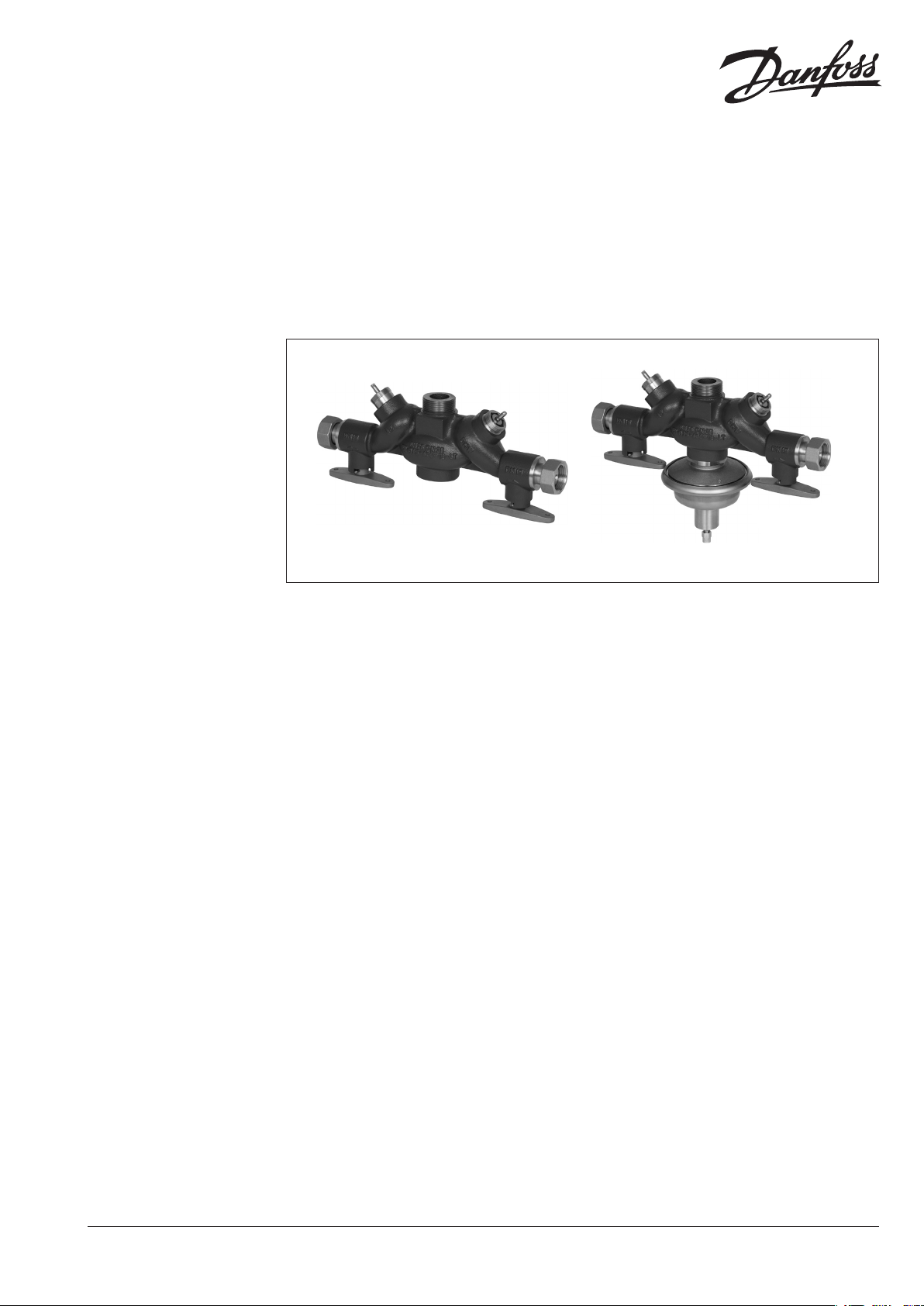
Integrated controller with two control valves and diff. pressure controller (PN 25)
IVPMM-F – flow mounting, fixed differential pressure setting
IVMM – flow mounting, no differential pressure controller
Description
IVMM
IVPMM-F
IVPMM-F is an integrated controller which
consist of two control valves and one self-acting
differential pressure controller.
IVMM-F is an integrated controller which consist
of two control valves.
In addition both controllers are, on both outlets,
equipped with ball valves.
Controllers are developed for use primarily in
district heating systems. The differential pressure
controller (DP) closes on rising differential
pressure.
Innovative design enables space saving due to
reduction of number components and simple,
fast and reliable mounting into substation.
Two control valves are developed to control
heating circuit (HE) and domestic hot water
(DHW) production. Kvs value on heating side is
adjustable (factory setting is max kVS).
There are other possibilities to use controllers as
well:
- to use both control valves for heating
FOR INTERNAL USE ONLY
- to use both control valves for domestic hot
water production; in this case HE valve insert
has to be set to max kVS value
In combination with Danfoss electrical actuators
AMV(E) can be controlled by ECL electronic
controllers.
Control valves are used together with Danfoss
electrical actuators:
- AMV 150
- AMV(E) 101) / AMV(E) 20 / AMV(E) 30
- AMV(E) 131) / AMV(E) 23 / AMV(E) 33 with
spring return function
- AMV 20SL / AMV 23SL / AMV 30SL with stroke
limitation
1)
Actuator(s) can not be combin ed with kVS values 6.3, 10 and 16
2)
can be combined with IVPMM -F DN 25 only.
Remark:
For instantaneous domestic hot water
production (with heat exchanger) use of AMV(E)
30(SL) or AMV(E) 33 electrical actuators is
recommended.
Main data:
• DNvalues
- DP 25, 40
- HE, DHW 15, 25
•kVS values
- Heating* 2.5-16 m3/h
- DHW 1.0-16 m3/h
* kVS value on heating s ide is adjustable
•PN25
•FixedΔpsettingrange:0.8bar
•Temperature:
- Circulation water / glycolic water up to 30%:
•Connections:
- Ext. thread (inlet) and int. thread (outlet)
1), 2)
2 … 150 °C
DH-SMT/SI
VD.LR.G1.02 © Danfoss 05/2010
1
Page 2
Data sheet Integrated controllers IVPMM-F, IVMM (PN 25)
Ordering
Example:
Integrated controller with two
control valves and differential
pressure controller, k
k
1.0, PN 25,
VS DHW
fixed ∆p setting 0.8, t
- 1× IVPMM-F controller
Code No: 003H7000
Option:
- 1× Impulse tube set AV, R ¹/”
Code No: 003H6852
- 1× Weld-on tailpieces
Code No: 003 H6910
The controller will be delivered
completely assembled. External
impulse tube set (AV) and electrical
actuators AMV(E) must be ordered
separately.
VS HE
max
2.5,
150 °C
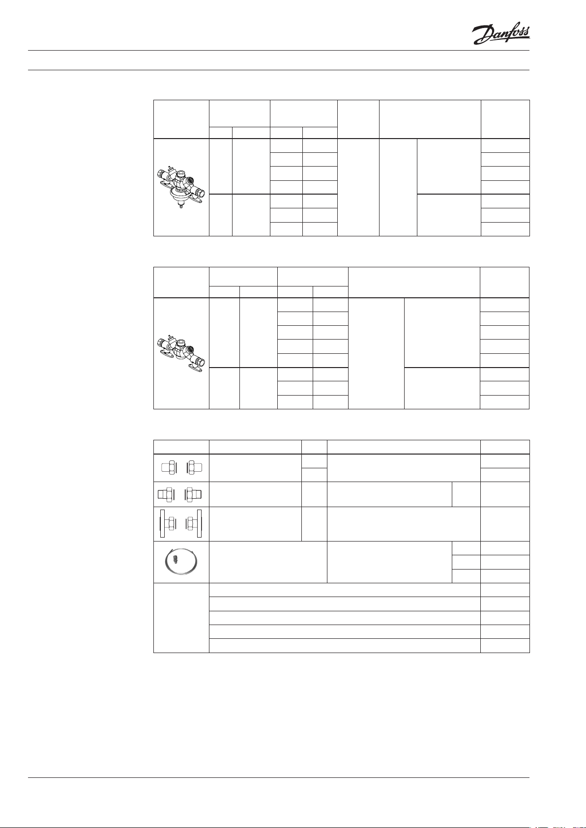
IVPMM-F Controller
k
Picture
* kVS value on heating s ide is adjustable (see kVS setting dia grams section)
DN
DP HE, DHW HE
25 15
40 25
vs
(m3/h)
* DHW (bar)
max
2.5 1.0
4.0 1.6 003 H7001
6.3 2.5 003H7002
6.3 4.0 003H7003
10 6.3
10 10 003H7005
16 16 003H7006
setting
IVMM Controller
k
Picture
* kVS value on heating s ide is adjustable (see kVS setting dia grams section)
DN
DP HE, DHW HE
25 15
40 25
vs
(m3/h)
* DHW
max
2.5 1.0
4.0 1.6 0 03 H7 011
6.3 2.5 00 3H7012
6.3 4.0 00 3H70 13
6.3 6.3 00 3H7014
10 6.3
10 10 0 03H7016
16 16 0 03 H7017
Δp
range
0.8
Cylndrical
ISO228/1
Connection Code No.
inlet ext. thread
G 1 ¼” A
outlet int. thread
Cyl.
thread
acc. to
ISO228/1
Connection Code No.
thread
acc. to
(nut) G 1” A
inlet ext. thread
G 2”A
out. int. thread
(nut) G 2”A
inlet ext. thread
G 1 ¼” A
outlet int. thread
(nut) G 1” A
inlet ext. thread
G 2”A
out. int. thread (nut)
G 2”A
003H7000
003H7004
003 H7010
00 3H70 15
Accessories
Picture Type designation DN Connection Code No.
Weld-on tailpieces
External thread tailpieces 25
Flange tailpieces 25
FOR INTERNAL USE ONLY
* Compression fit ting consists of a nipple, comp ression ring and nut.
Impulse tube set AV
* 10 compression fittings for imp. tube connection to pipe, Ø6 × 1 mm R ⁄” 003H6857
* 10 compression fittings for imp. tube connection to pipe, Ø6 × 1 mm R ⁄” 003H6858
* 10 compression fittings for imp. tube connection to pipe, Ø6 × 1 mm R ⁄” 003H6859
* 10 compression fittings for imp. tube connection to actuator, Ø6 × 1 mm G ⁄” 0 03H6 931
Shut off valve Ø6 mm 003 H0276
25
40 00 3H6 912
Conical ext. thread acc. to
EN10226-1
FlangesPN25,acc.to
EN1092-2
Description:
-
1x copper tube Ø6 × 1 × 1500 mm
- 1x compression fitting*
for imp.
tube con. to pipe Ø6 × 1 mm
-
R 1” 003H6904
R ⁄” 003H 6852
R ⁄” 003H6853
R ⁄” 003H6854
003 H6910
00 3H 6917
2
VD.LR.G1.02 © Danfoss 05/2010
DH-SMT/SI
Page 3
Data sheet Integrated controllers IVPMM-F, IVMM (PN 25)
Ordering (con tinuo us)
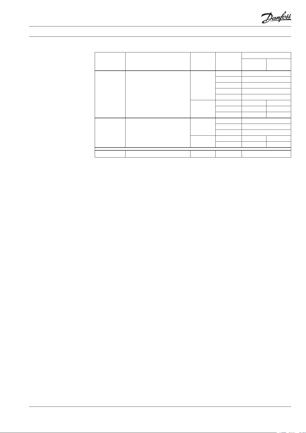
Service kits
Picture Type designation
Control valve insert DHW
Control valve insert HE
Ball valve stuffing box 25, 40 - 003H7058
DN
(mm)
25
40
25
40
k
vs
(m3/h)
1.0 003H7040
1.6 0 03H70 41
2.5 003H7042
4.0 003H7043
6.3 003H7044
6.3 003H7045 003H7048
10 003H7046 003H70 49
16 0 03H7047 003H7050
2.5 00 3H7051
4.0 003H7052
6.3 003H7053
10 003H7054 003H7056
16 003H7055 003H7057
Code No.
IVPMM-F IVMM
DH-SMT/SI
FOR INTERNAL USE ONLY
VD.LR.G1.02 © Danfoss 05/2010
3
Page 4
Data sheet Integrated controllers IVPMM-F, IVMM (PN 25)
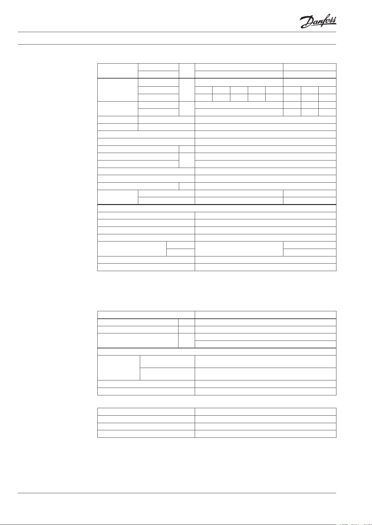
Technical data
Valves
Nominal
diameter
kVS value
Stroke
Control ratio HE > 1:50
Control ratio DHW > 1:50
Control characteristic HE, DHW Split characteristics
Leakage acc. to standard IEC 534 0.05 % of k
Nominalpressure PN 25
Max. differential pressure
Max. closing pressure 8
Medium Circulation water / glycolic water up to 30%
Medium pH Min. 7, max. 10
Medium temperature ºC 2 … 150
Connections
Materials
Valve body DuctileironEN-GJS-400-18-LT(GGG40.3)
Valve seat DP Stainless steel,mat.No.1.4404NC
Valve seat HE, DHW Stainless steel,mat.No.1.4 057
Valve cone DP Stainless steel,mat.No.1.43 01
Valve cone HE, DHW
Sealing DP EPDM
Sealing HE, DHW EPDM
Note:
HE - heating valve , DHW - domestic hot water valve, DP - d iff. p ressure controller
Diff. pressure control ler capacity has been c hosen for 100% flow on one control valve an d max. 30% flow on the second cont rol valve at
the same time (reaso n is low probability of 100% flo w on both control valves).
inlet DP
outlets HE, DHW 15 25
DP
HE (max.) 2.5 4 6.3 6.3 6.3 10 10 16
DHW 1.0 1.6 2.5 4.0 6.3 6.3 10 16
HE
DHW 5 5 7 10
inlet DP ext. thread G 1 ¼” A ext. thread G 2” A
outlets HE, DHW int. thread (nut) G 1” A int. thread (nut) G 2” A
DN
m3/h
mm
bar
IVPMM-F
IVMM St. steel,No.1.4305
Stainless steel,mat.No.1.43 05
25 40
28 62
5 7 7 10
value
vs
12
CuZn36Pb2As (DZR)
Differential Pressure Actuator
Typ e IVPMM-F
Actuator size cm
Nominalpressure PN 25
Diff. pressure setting range bar
Materials
Upper casing of
Actuator housing
FOR INTERNAL USE ONLY
Diaphragm EPDM
Impulse tube Copper tube Ø 6 × 1 mm
diaphragm
Lower casing of
diaphragm
2
Dezincing free brass CuZn36Pb2As
Stainless steel,mat.No.1.43 01
54
0.8
(fixed setting)
Ball valves
Body DuctileironEN-GJS-400-18-LT(GGG40.3)
Connection piece Dezincing free brass CuZn36Pb2As
Ball Stainlesssteel,mat.No.1.4301
Sealing PTFE/Graphite
4
VD.LR.G1.02 © Danfoss 05/2010
DH-SMT/SI
Page 5

Data sheet Integrated controllers IVPMM-F, IVMM (PN 25)
Application principles
IVPMM-F IVPMM-F
Installation positions
IVPMM-F
Controllers can be installed in any position,
except with (connection neck for) electrical
actuator oriented downwards.
IVPMM-F
DH-SMT/SI
FOR INTERNAL USE ONLY
Electrical actuator
Note!
Installation p ositions for electrical ac tuator AMV(E) have to be
observed as we ll. Please see relevant Data Sheet .
VD.LR.G1.02 © Danfoss 05/2010
5
Page 6

Data sheet Integrated controllers IVPMM-F, IVMM (PN 25)
Pressure temperature
diagram
EN-GJS- 400-18 -LT (GGG 40.3)
kVS setting diagrams
(valid for HE side only)
working
Maximum allowed operating pressure as a function of medium temperature (according to EN 1092-3).
area
kVS 2.5 kVS 4.0
kVS 6.3 kVS 10
FOR INTERNAL USE ONLY
kVS 16 - IVMM kVS 16 - IVPMM-F
6
VD.LR.G1.02 © Danfoss 05/2010
DH-SMT/SI
Page 7

Data sheet Integrated controllers IVPMM-F, IVMM (PN 25)
Design
IVMM
1. Valve body
2. Control valve insert - Heating
3. Control valve cone - Heating
4. Control valve insert Domestic hot water
5. Control valve cone - Domestic
hot water
6. Connection nut (G1 or G2)
7. Connection piece
8. Integrated ball valve
9. Integrated ball valve handle
IVPMM-F
1. Valve body
2. Pressure relieved valve seat DP controller
3. Valve cone - DP controller
4. Valve stem - DP controller
5. Differential pressure actuator
6. Upper casing of diaphragm
7. Lower casing of diaphragm
8. Control diaphragm
9. Spring for DP control
10. Safety valve
11. Pressure connection
12. Control valve insert - Heating
13. Control valve cone - Heating
14. Control valve insert -
Domestic hot water
1 5 . Control valve cone - Domestic
hot water
16. Connection nut (G1 or G2)
1 7 . Connection piece
18. Integrated ball valve
19. Integrated ball valve handle
Function Temperature control
Medium temperatures on heating and domestic
hot water secondary sides are being controlled
FOR INTERNAL USE ONLY
by electronic controller (weather compensator).
Electronic controller based on it’s algorithm
adequately, via electrical actuators, opens or
closes both valves.
DH-SMT/SI
VD.LR.G1.02 © Danfoss 05/2010
Differential pressure control
Pressure changes from the flow and return
pipeline are being transferred through the
impulse tube and control drain in the actuator
stem to the actuator chambers and act on
control diaphragm. Control valve closes on
rising differential pressure and opens on falling
differential pressure to maintain constant
differential pressure.
7
Page 8

Data sheet Integrated controllers IVPMM-F, IVMM (PN 25)
Dimensions
IVMM DN 25 IVPMM-F DN 25
IVMM, IVPMM-F DN 25
IVMM, IVPMM-F DN25 HE, DH
Actuator L1 L2 L3 L4 H1 H2 H3 H4 W1 W2
AMV(E) 10 181 177 179 174 158 153 193 188 31 94
FOR INTERNAL USE ONLY
8
VD.LR.G1.02 © Danfoss 05/2010
AMV(E) 13 192 187 18 4 179 169 16 3 203 198 31 94
AMV(E) 20, 30 194 189 202 197 179 174 216 2 11 53 104
AMV(E) 23, 33 2 11 206 201 196 17 9 174 216 2 11 53 104
AMV(E) 150
1)
can be combined with IVPM M-F DN 25 only.
1)
170 165 169 16 5 14 7 142 168 162 29 64
DH-SMT/SI
Page 9

Data sheet Integrated controllers IVPMM-F, IVMM (PN 25)
Dimensions
IVMM DN 40
IVMM, IVPMM-F DN 25
DH-SMT/SI
IVMM, IVPMM-F DN40 HE, DH
FOR INTERNAL USE ONLY
Actuator L1 L2 L3 L4 H1 H2 H3 H4 W1 W2
AMV(E) 10 206 201 203 198 167 162 202 197 31 94
AMV(E) 13 217 212 209 204 17 8 173 212 207 31 94
AMV(E) 20, 30 219 214 226 221 188 183 225 220 53 104
AMV(E) 23, 33 236 2 31 226 221 188 183 225 220 53 10 4
VD.LR.G1.02 © Danfoss 05/2010
9
Page 10

Data sheet Integrated controllers IVPMM-F, IVMM (PN 25)
FOR INTERNAL USE ONLY
10
VD.LR.G1.02 © Danfoss 05/2010
DH-SMT/SI
Page 11

Data sheet Integrated controllers IVPMM-F, IVMM (PN 25)
DH-SMT/SI
FOR INTERNAL USE ONLY
VD.LR.G1.02 © Danfoss 05/2010
11
Page 12

Data sheet Integrated controllers IVPMM-F, IVMM (PN 25)
FOR INTERNAL USE ONLY
12
VD.LR.G2.02
Produce d by Danfoss A/S © 05/2010
 Loading...