

Page 1
MAKING MODERN LIVING POSSIBLE
Operating Instructions
VLT® ISD Encoder Box
Page 2

Page 3

Contents
Contents
VLT® ISD Encoder Box Operating Instructions
1 General Information
1.1 Important Safety Warnings
1.2 Copyright
1.3 Disclaimer
1.4 Approvals
1.5 Service and Support
2 Introduction
2.1 System Overview
2.2 Terminology
2.3 Purpose of the Operating Instructions
2.4 Additional Resources
3 Safety Instructions
3.1 Symbols used in this Manual
3.2 General
3.3 Safety Instructions and Precautions for the ISD 410 Servo System
3.4 Qualified Personnel
4
4
4
4
4
4
5
5
6
6
6
7
7
7
7
9
3.5 Due Diligence
3.6 Intended Use
3.7 Foreseeable Misuse
4 Description
4.1 Supported Encoders
4.2 ISD Encoder Box Display
4.3 Connection Cable/Cabling
4.3.1 ISD Servo System with 1 Connection Box 12
4.3.2 ISD Servo System with 2 Connection Boxes 13
4.3.3 Connections 14
4.3.3.1 24 V Power Supply (X201) 14
4.3.3.2 CAN Connector (X501 & X502) 15
4.3.3.3 RS 422 I; AB, BiSS and SSI Encoder Connector (X601) 15
4.3.3.4 RS 422 II; Additional Encoder Connector (X602) 16
4.3.3.5 SD Card Slot 16
5 Installation/Fitting
9
9
10
11
11
11
12
17
5.1 Transport and Delivery
5.1.1 Scope of Delivery 17
5.1.2 Transport 17
5.1.3 Inspection on Receipt 17
MG75F102 - VLT® is a registered Danfoss trademark 1
17
Page 4

Contents
VLT® ISD Encoder Box Operating Instructions
5.2 Safety Measures during Installation
5.3 Installation Environment
5.4 Preparation for Installation
5.5 Mechanical Installation
5.5.1 Earthing (Grounding) the Encoder Box 18
5.5.2 Mounting 18
5.5.3 Demounting 18
5.6 Electrical Installation
5.6.1 Electrical Environmental Conditions 18
5.6.2 24 V Power Supply Requirements 18
5.6.3 Connecting the CAN Cable 18
5.6.4 Connecting the Encoder Cable 18
5.6.5 Inserting the SD Card 19
5.6.6 Connecting the 24 V Power Supply 19
6 Commissioning
6.1 Standard Configuration
6.2 Parameter Setting
17
17
17
18
18
20
20
20
6.2.1 Encoder Box Parameter List 20
6.2.2 Changing the Parameters 20
6.2.3 CAN Settings 20
6.2.4 CAN-ID Setting 21
6.3 Switching the Encoder Box on
7 Operation
7.1 Operating Display
7.1.1 Operating LEDs 22
7.1.2 Display Mode 23
7.1.3 7-Segment Display 23
7.1.4 <SET> Push Button 24
7.1.5 <CAN-ID> BCD Switch 24
7.1.6 Service Interface 24
7.2 Display via Toolbox and CoDeSys
8 Faults
8.1 Emergency
21
22
22
24
25
25
8.2 Error History
8.3 Debugging
8.4 Under-Voltage / Power-Failure Behaviour
8.4.1 Under-Voltage during Power-Up 26
8.4.2 Sudden Voltage Drop 26
2 MG75F102 - VLT® is a registered Danfoss trademark
25
25
25
Page 5

Contents
VLT® ISD Encoder Box Operating Instructions
8.4.3 Power Failure 26
8.5 Troubleshooting
9 Maintenance and Repair
9.1 Maintenance tasks
9.2 Inspection during Operation
9.3 Repair
10 Decommissioning and Disposal
10.1 Decommissioning
10.2 Dismounting
10.3 Recycling and Disposal
10.3.1 Recycling 29
10.3.2 Disposal 29
11 Specifications
11.1 Nameplate
11.2 Storage
11.3 Characteristic Data
27
28
28
28
28
29
29
29
29
30
30
30
30
11.4 Dimensions
11.4.1 Front View 31
11.4.2 Side View 32
12 Appendix
12.1 Glossary
12.2 Encoder Box Parameters
12.3 Emergency Codes
12.4 Error Codes
Index
31
33
33
36
39
39
40
MG75F102 - VLT® is a registered Danfoss trademark 3
Page 6
R
C US
General Information
VLT® ISD Encoder Box Operating Instructions
11
1 General Information
1.1 Important Safety Warnings
WARNING
HIGH VOLTAGE
The ISD 410 servo system contains components which
operate at a high voltage when connected to the electrical
supply network. A hazardous voltage is present on the
servomotors, the power supply module and the
connection box whenever they are connected to the mains
network. There are no indicators on the servomotor that
indicate the presence of mains voltage. This indication is
provided on the connection box. Installation, commissioning and maintenance may only be performed by
qualified staff. Incorrect installation, commissioning or
maintenance can lead to death or serious injury.
WARNING
UNINTENDED START
The ISD 410 servo system contains servomotors which are
connected to the electrical supply network and can start
running at any time. This may be caused by an external
switch, a CAN bus command, a reference signal, or clearing
a fault condition. Servomotors and all connected devices
must be in good operating condition. A deficient operating
condition may lead to death, serious injury, damage to
equipment or other material damage when the unit is
connected to the electrical supply network. Take suitable
measures to prevent unintended starts.
1.2
Copyright
Disclosure, duplication and sale of this document, as well
as communication of its content, are prohibited unless
explicitly permitted. Infringement of this prohibition incurs
liability for damages. All rights reserved with regard to
patents, utility patents and registered designs.
ISD is a registered trademark.
1.3 Disclaimer
No liability is assumed for any damage or breakdown
resulting from:
Failure to observe the information in the
•
instruction manuals
Unauthorised modifications to the ISD servo
•
system or its components
Operator error
•
Improper work on or with the ISD servo system
•
or its components.
1.4
Approvals
1.4.1 ISD 410 Servomotor, ISD Encoder Box
and ISD Connection Box
WARNING
DISCHARGE TIME
The servomotors, the connection box and the power
supply module contain DC link capacitors, that remain
charged for some time after the mains supply is switched
off at the power supply module.
To avoid electrical shock, fully disconnect the power
supply module from the mains before carrying out any
maintenance on the ISD servo system or its components.
Wait for at least the time listed below before carrying out
maintenance work:
Number Minimum waiting time (discharge time)
1-60 servomotors 10 minutes
Note: High voltage may still be present even if the LED on the
ISD connection box is not lit!
Table 1.1 Discharge Time
4 MG75F102 - VLT® is a registered Danfoss trademark
Table 1.2 Approvals for the ISD 410 Servomotor, ISD Encoder Box
and ISD Connection Box
ISD Power Supply Module
1.4.2
Table 1.3 Approvals for the ISD Power Supply Module
1.5
Service and Support
Contact your local service representative for service and
support:
http://www.danfoss.com/Contact/Worldwide/
Page 7
130BC480.12
1
2 3
4
5
6
7
9
101112
ISD Connection Box
Failure
Warning
Output (300V) OK
Stand-By
Output (90V) OK
Enable
Error
300V OK
90V OK
300V
Signal Outputs
10A
Signal Inputs
ISD Power Supply Module
AC/DC Power Supply 300VDC 8/10A
Run/Err
U
ZK
24V
Safe
Warn Err
CAN-ID
5V
CAN
RS232
Service
Set
2 8
6
4
Safety I Safety II
Fuse L I CAN 1.In CAN 2.In CAN 3.In CAN 4.In CAN 5.In
X11 X12 X13 X14 X15
Fuse L II CAN 1.Out CAN 2.Out CAN 3.Out CAN 4.Out CAN 5.Out
X21 X22 X23 X24 X25
0
8
Introduction
2 Introduction
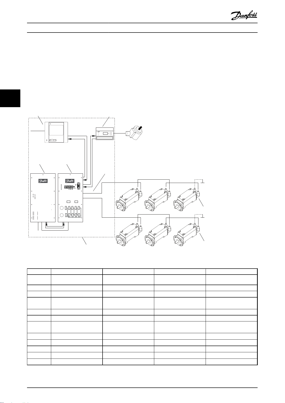
2.1 System Overview
VLT® ISD Encoder Box Operating Instructions
2 2
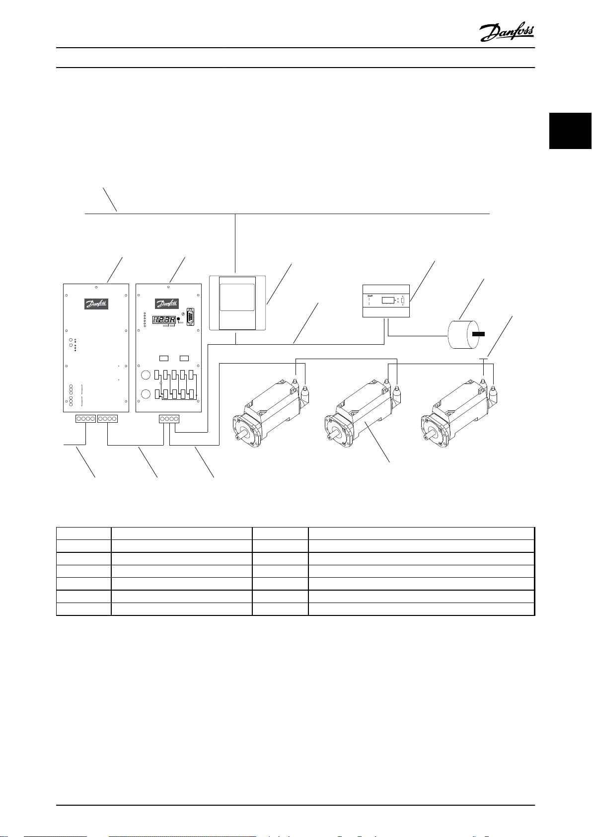
Illustration 2.1 ISD Servo System with 3 Servomotors
Number
Description Number Description
1 Ethernet 7 Master encoder
2 Power supply module 8 Terminating resistor
3 Connection box 9 ISD servomotor
4 Master 10 Hybrid cable (DC & CAN)
5 CAN line 11 DC line
6 Encoder box 12 AC line
Table 2.1 Legend to Illustration 2.1
The servomotors are self-contained distributed drives,
which means that the drive electronics is housed together
with the motor in the same casing. The motion control
software also runs independently in the servomotor; which
reduces the load on the higher-level control system.
A master system controls the servomotors. In this system
servomotors operated in a DC group are controlled by a
master system.
MG75F102 - VLT® is a registered Danfoss trademark 5
Page 8
Introduction
VLT® ISD Encoder Box Operating Instructions
Several motors can be operated in a group using a hybrid
cable. This cable carries the DC supply voltage and the
CAN bus signals. The ISD 410 servo system is designed to
22
accommodate up to 60 ISD 410 servomotors and consists
of:
1 Power supply module
•
1 Connection box
•
1 Encoder Box
•
Servomotors
•
1 Master
•
Hybrid cables
•
NOTE
The ISD 410 servomotors cannot be used in other servo
systems from other manufacturers!
Motors from other manufacturers cannot be used in the
Danfoss ISD 410 servo system!
2.2 Terminology
ISD Integrated Servo Drives
ISD servo system Complete system including all components.
ISD master Control system hardware
ISD master system Control system hardware and software
ISD servo drive ISD servomotor with hybrid cable
Table 2.2 Terminology
2.3
Purpose of the Operating Instructions
The purpose of these operating instructions is to describe
the Danfoss ISD encoder box exclusively in the context of
a Danfoss ISD 410 servo system.
These operating instructions contain information about:
Installation
•
Commissioning
•
Operation
•
Troubleshooting
•
Maintenance and repair
•
These operating instructions are intended for use by
qualified personnel. Read these operating instructions in
full in order to use the servo system safely and professionally, and pay particular attention to the safety
instructions and general warnings. These operating
instructions are an integral part of the ISD encoder box.
Keep these operating instructions available with the servo
system at all times.
Compliance with the information in the operating
instructions is a prerequisite for:
Trouble-free operation
•
Recognition of product liability claims
•
Therefore, read these operating instructions before
working with the encoder box!
The operating instructions also contain important service
information. The operating instructions should therefore be
kept close to the encoder box.
2.4 Additional Resources
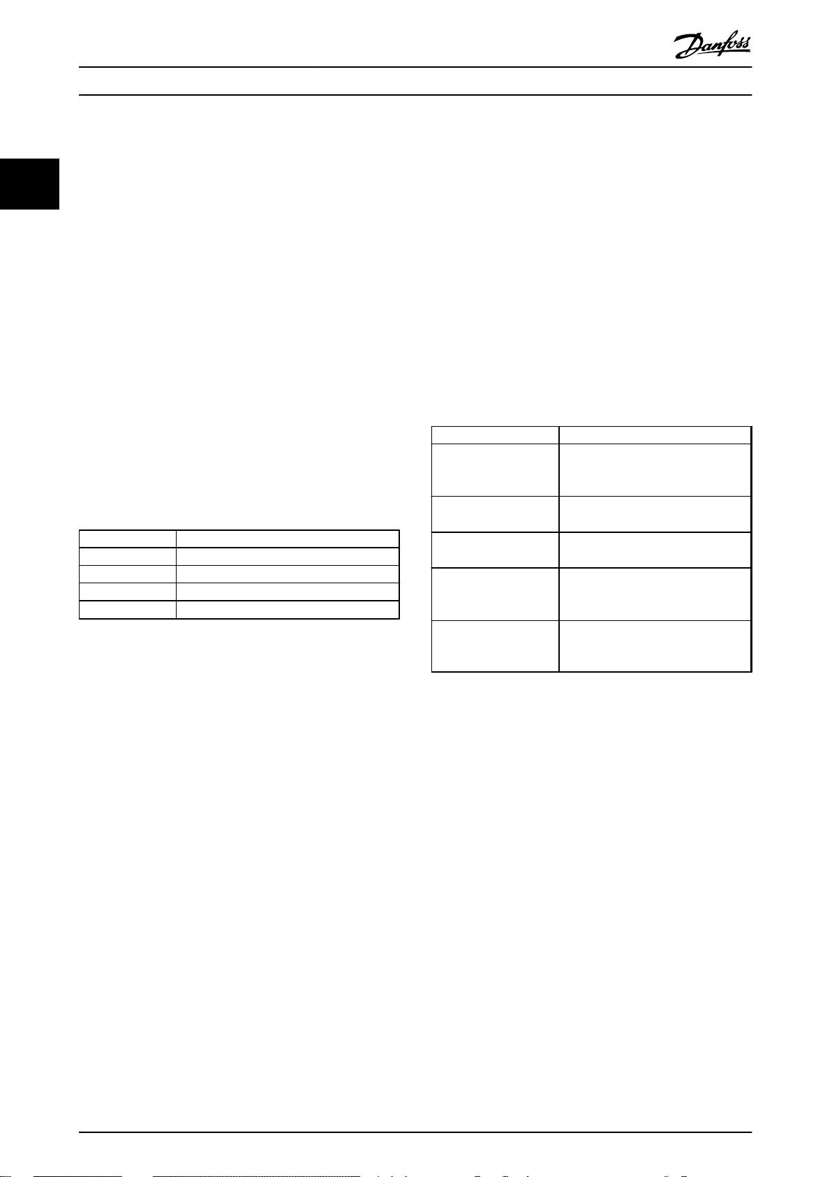
Available documents for the ISD 410 servo system:
Document Contents
VLT® ISD 410
Servomotor Operating
Instructions
VLT® ISD Encoder Box
Operating Instructions
VLT® ISD Connection Box
Operating Instructions
VLT® ISD Power Supply
Module Operating
Instructions
VLT® ISD 410 Design
Guide
Table 2.3 Available Documents for the ISD 410 Servo System
Technical literature for Danfoss drives is also available
online at http://www.danfoss.com/BusinessAreas/DrivesSolutions/Documentations/Technical+Documentation.htm.
Firmware updates may be available. When firmware
updates are available, they can be downloaded from the
www.danfoss.com website. For further information see the
VLT® ISD 410 Design Guide.
Information about the commissioning
and operation of the servomotors
Information about the commissioning
and operation of the encoder box
Information about the commissioning
and operation of the connection box
Information about the commissioning
and operation of the power supply
module
Information about the construction
and commissioning of the ISD 410
servo system
6 MG75F102 - VLT® is a registered Danfoss trademark
Page 9
Safety Instructions
VLT® ISD Encoder Box Operating Instructions
3 Safety Instructions
3.1 Symbols used in this Manual
The following symbols are used in this document.
WARNING
Indicates a potentially hazardous situation which, if not
avoided, could result in death or serious injury.
WARNING
HAZARDOUS SITUATION
If the servomotor or the bus lines is/are incorrectly
connected, there is a risk of death, serious injury or
damage to the unit.
Always comply with the instructions within these operating
instructions, as well as national and local safety
regulations. Also read the operating instructions for the
other components of the servo system.
3
3
CAUTION
Indicates a potentially hazardous situation which, if not
avoided, may result in minor or moderate injury. It may
also be used to alert against unsafe practices.
CAUTION
Indicates a situation that may result in equipment or
property-damage-only accidents.
NOTE
Indicates highlighted information that should be regarded
with attention to avoid mistakes or operate equipment at
less than optimal performance.
3.2 General
The following safety instructions and precautions relate to
the ISD 410 servo system. The number of servomotors in
the servo system is not significant.
Read the safety instructions carefully before starting to
work in any way with the servo system.
Pay particular attention to the safety instructions in the
relevant sections of this instruction manual.
Also observe the safety instructions and precautions in the
instruction manuals for the other system components.
WARNING
HIGH VOLTAGE
The ISD 410 servo system contains components which
operate at a high voltage when connected to the electrical
supply network.
A hazardous voltage is present on the servomotors, the
power supply module and the connection box whenever
they are connected to the mains network.
There are no indicators on the servomotor that indicate
the presence of mains voltage. This indication is provided
at the connection box. Installation, commissioning and
maintenance may only be performed by qualified staff.
Incorrect installation, commissioning or maintenance can
lead to death or serious injury.
3.3 Safety Instructions and Precautions for
the ISD 410 Servo System
Read the safety instructions carefully before starting to
work in any way with the servo system. Compliance with
the safety instructions and precautions is necessary at all
times.
Orderly and proper transport, storage, fitting and
•
installation, as well as careful operation and
maintenance, are essential for the trouble-free
and safe operation of this servo system and its
components.
Only suitably trained and qualified staff may work
•
on the servo system and its components or in its
vicinity. See chapter 3.4 Qualified Personnel.
Use only accessories and spare parts approved by
•
the manufacturer.
Comply with the specified ambient conditions.
•
The information in these operating instructions
•
about the use of available components is
provided solely by way of examples of
applications and suggestions.
The plant engineer or system engineer is
•
personally responsible for checking the suitability
of the supplied components and the information
provided in this document for the specific
application concerned:
- for compliance with the safety
regulations and standards relevant to
the specific application concerned.
- for implementing the necessary
measures, changes and extensions.
Commissioning the servo system and its
•
components is not allowed until it has been
ascertained that the machine, system or plant in
which they are installed conforms to the statutory
provisions, safety regulations and standards that
apply in the country of use to that application.
MG75F102 - VLT® is a registered Danfoss trademark 7
Page 10
Safety Instructions
VLT® ISD Encoder Box Operating Instructions
3
Operation is allowed only in compliance with the
•
national EMC regulations for the application
concerned.
See the VLT® ISD 410 Design Guide for information
•
regarding EMC-compliant installation of the servo
system.
Compliance with the limit values specified by
•
national regulations is the responsibility of the
producer of the plant, system or machine.
Compliance with the specifications, connection
•
conditions and installation conditions in this
instruction manual is mandatory.
The safety regulations and safety provisions of
•
the country in which the equipment is used must
be observed.
Care must be taken to ensure that orderly
•
protective earthing of the equipment, which
protects the user against the supply voltage and
protects the power supply module against
overload, is performed in accordance with local
and national regulations.
Overload protection for the servomotor can be
•
programmed using the master system. For more
information, see Programming in the VLT
Design Guide.
Do not remove or replace the SD card on the
•
encoder box during operation, otherwise the
contents of the SD card could be destroyed.
Switch the encoder box off and wait 10 seconds
before removing the SD card.
®
ISD 410
WARNING
EARTHING HAZARD
For reasons of operator safety, the components of the
servo system must be earthed correctly in accordance with
national or local electrical regulations and the information
in these operating instructions. The earth leakage current
is greater than 3.5 mA. Improper earthing of the
servomotor may result in death or serious injury.
Operational Safety
Safety-related applications are allowed only if
•
they are explicitly and unambiguously mentioned
in the VLT® ISD 410 Design Guide. Otherwise they
are not allowed.
All applications that can cause hazards to people
•
or damage to property are safety-related
applications.
The stop functions implemented in the software
•
of the master system do not interrupt the mains
voltage supply to the power supply module and
are therefore not allowed to be used as safety
switches for the servo system.
The motor can be brought to a stop by a
•
software command or a zero speed setpoint, but
DC voltage remains present on the servomotor
and/or mains voltage in the power supply
module. If personal safety considerations (e.g. risk
of personal injury caused by contact with moving
machine parts after an unintended start) make it
necessary to ensure that an unintended start
cannot occur, these stop functions are not
sufficient. In this case the servo system must be
detached from the mains network or a suitable
stop function must be implemented.
When the servomotor is stopped, it may start up
•
again on its own if the circuitry of the servomotor
is defective or after the elimination of a
temporary overload, a problem with the supply
voltage or a problem with the servomotor. If
personal safety considerations (e.g. risk of
personal injury caused by contact with moving
machine parts after an unintentional start) make
it necessary to ensure that an unintended start
cannot occur, the normal stop functions of the
servomotor are not sufficient. In this case the
servo system must be disconnected from the
mains network or a suitable stop function must
be implemented.
The servomotor may start running unintentionally
•
during parameter configuration or programming.
If this can pose a risk to personal safety (e.g. risk
of personal injury due to contact with moving
machine parts), unintended motor starting must
be prevented, for example by using the Safe Stop
function or by safe disconnection of the
servomotors.
Do not disconnect the cables from the
•
servomotor while the servo system is connected
to mains voltage. Ensure that the mains supply is
disconnected and the required waiting time has
elapsed before disconnecting or connecting the
hybrid cable or disconnecting cables from the
connection box and/or the power supply module.
8 MG75F102 - VLT® is a registered Danfoss trademark
Page 11
Safety Instructions
VLT® ISD Encoder Box Operating Instructions
In addition to the L1, L2 and L3 supply voltage
•
inputs on the power supply module, the servo
system has other supply voltage inputs, including
external DC 24 V. Before commencing repair
work, check that all supply voltage inputs have
been switched off and that the necessary
discharge time for the intermediate circuit
capacitors has elapsed.
The supply of power to the servo system must be
•
switched off for repair work. Before disconnecting
or connecting the hybrid cable or disconnecting
cables from the connection box and/or the power
supply module, ensure that the mains supply is
disconnected and the necessary discharge time
has elapsed.
WARNING
DISCHARGE TIME
The servomotors, the connection box and the power
supply module contain DC link capacitors, that remain
charged for some time after the mains supply is switched
off at the power supply module.
To avoid electrical shock, fully disconnect the power
supply module from the mains before carrying out any
maintenance on the ISD servo system or its components.
Wait for at least the time listed below before carrying out
maintenance work:
Number Minimum waiting time (discharge time)
1-60 servomotors 10 minutes
Note: High voltage may still be present even if the LED on the
ISD connection box is not lit!
Table 3.1 Discharge Time
CAUTION
Never connect or disconnect the hybrid cable to or from
the servomotor when voltage is present. Doing so will
damage the electronic circuitry. Observe the discharge
time for the DC link capacitors.
3.4 Qualified Personnel
Installation, commissioning and maintenance of the
ISD 410 servo system may only be carried out by qualified
personnel.
For the purposes of this document and the safety
instructions in this document, qualified staff are trained
staff who are authorised to fit, install, commission, earth
and label equipment, systems and circuits in accordance
with the standards for safety technology and who are
familiar with the safety concepts of automation
engineering.
Additionally, the personnel must be familiar with all the
instructions and safety measures described in these
operating instructions.
They must have suitable safety equipment and be trained
in first aid.
3.5 Due Diligence
The operator and/or fabricator must ensure that:
the servo system and its components are used
•
only as intended
the components are operated only in a perfect
•
operational condition
the operating instructions are always available
•
near the servo system in complete and readable
form
the servo system and its components are fitted,
•
installed, commissioned and maintained only by
adequately qualified and authorised personnel
these personnel are regularly instructed on all
•
relevant matters of occupational safety and
environmental protection, as well as the contents
of the operating instructions and in particular the
instructions it contains
the product markings and identification markings
•
applied to the components, as well as safety and
warning instructions, are not removed and are
always kept in a legible condition
the national and international regulations
•
regarding the control of machinery and
equipment, that are applicable at the place of use
of the servo system, are complied with
the users always have all current information
•
relevant to their interests about the servo system
and its use and operation
3.6
Intended Use
The components of the ISD servo system are intended to
be installed in machines used in commercial and industrial
environments.
To ensure that the product is used as intended, the
following conditions must be fulfilled before use:
Everyone who uses Danfoss products in any
•
manner must read and understand the
corresponding safety regulations and the
description of the intended use
Hardware must be left in its original state, which
•
means that no structural changes may be made
to the hardware
3
3
MG75F102 - VLT® is a registered Danfoss trademark 9
Page 12

3
Safety Instructions
Software products may not be reverse-engineered
•
and their source code may not be altered
Damaged or faulty products may not be installed
•
or put into service
It must be ensured that the products are installed
•
in conformance with the regulations mentioned
in the documentation
Any specified maintenance and service intervals
•
must be observed
All protective measures must be complied with
•
Only the components described in these
•
operating instructions may be fitted or installed.
Third-party devices and equipment may be used
only in consultation with Danfoss
The documentation must be read completely and
•
correctly followed
The servo system may not be used in the following
application areas:
VLT® ISD Encoder Box Operating Instructions
Areas with potentially explosive atmospheres
•
Mobile or portable systems
•
Floating or airborne systems
•
Inhabited facilities
•
Sites where radioactive materials are present
•
Areas with extreme temperature variations or in
•
which the maximum rated temperatures may be
exceeded
Under water
•
3.7
Foreseeable Misuse
Any use not expressly approved by Danfoss constitutes
misuse. This also applies to failure to comply with the
specified operating conditions and applications.
Danfoss assumes no liability of any sort for damage attributable to improper use.
10 MG75F102 - VLT® is a registered Danfoss trademark
Page 13
130BD085.10
Run/Err
Power
CAN I
Warn
Err
0
CAN-ID
CAN II
RS232
Service
Set
2 8
6
4
ISD Encoder Box
Description
VLT® ISD Encoder Box Operating Instructions
4 Description
The encoder box is intended to be used in an environment
where several servo drives require an exact position in
order to follow a specific curve profile, or to determine the
speed at which the machine is running. The position can
be read either from an externally connected encoder or
from a software encoder simulation running on the
encoder box.
The encoder box reads the position values from
•
an absolute or incremental encoder, applies a
precise timestamp and sends them periodically to
the CAN.
DS301 and DS406 of the CAN-CiA-Standard are
•
implemented in the encoder box.
The object dictionary is detailed in the VLT
•
ISD 410 Design Guide.
The encoder box fulfils the requirements of class
•
2 encoders according to the DS406 CAN standard.
When simulating the encoder the speed and
•
ramp can be set.
If an error or unexpected event occurs the
•
encoder box transmits an emergency message
(error code).
Every error is logged in the encoder box memory
•
and remains in the error history. However a
maximum of 6 errors and 6 warnings are saved
and older events are overwritten (first-in-first-out
principle).
®
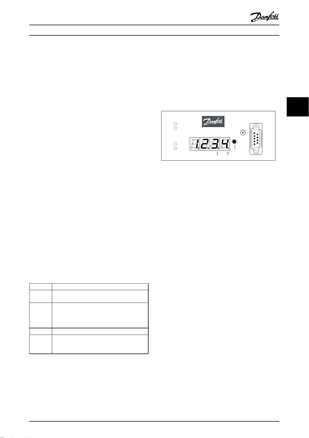
4.2
ISD Encoder Box Display
The display shows the operating status of the encoder box.
Illustration 4.1 Encoder Box Display
See chapter 7.1 Operating Display for detailed information
on the display.
4 4
4.1
Supported Encoders
Encoder Description
SSI All single-turn SSI encoders are compatible up to
28 bit.
SSI-CRC All single-turn SSI-CRC encoders are compatible up
to 28 bit.
The CRC Polynomial is fixed and the CRC-Check can
be enabled or disabled.
QEP All QEP encoders are compatible up to 24 bit.
BiSS All single-turn BiSS encoders are compatible up to
32 bit.
The CRC polynomial can be parameterised.
Table 4.1 Supported Encoders
MG75F102 - VLT® is a registered Danfoss trademark 11
Page 14
130BD089.11
1 2
5
3
4
4
6
ISD Connection Box
Failure
Warning
Output (300V) OK
Stand-By
Output (90V) OK
Enable
Error
300V OK
90V OK
300V
Signal Outputs
10A
Signal Inputs
ISD Power Supply Module
AC/DC Power Supply 300VDC 8/10A
Run/Err
U
ZK
24V
Safe
Warn Err
CAN-ID
5V
CAN
RS232
Service
Set
2 8
6
4
Safety I Safety II
Fuse L I CAN 1.In CAN 2.In CAN 3.In CAN 4.I n CAN 5.In
X11 X12 X13 X14 X15
Fuse L II CAN 1.Out CAN 2.Out CAN 3.Out CAN 4.Out CAN 5.Out
X21 X22 X23 X24 X25
B
ERGHOF
AC DC 300 V
ISD 410
ISD 410
DC+CAN
DC+CAN
0
CAN
CAN
Ethernet
7
Description
VLT® ISD Encoder Box Operating Instructions
4.3 Connection Cable/Cabling
The encoder box is connected to the ISD servo system via the CAN bus.
The encoder is connected via an RS 422 interface.
The maximum cable length between the encoder box and the encoder is limited to 50 m, other than BiSS encoders with
CRC at 8 MHz, which are limited to 10 m.
4.3.1 ISD Servo System with 1 Connection Box
44
The ISD servo system is set up with 1 connection box when the servomotors are used in ISD curve mode.
Illustration 4.2 ISD Servo System with 1 ISD Connection Box
No.
1 ISD Power Supply Module – – –
Name Line Type Cross-section Flexible Cable
2 ISD Connection Box – – –
3 Feed cable Hybrid cable (DC & CAN)
4 Terminating resistor Connector with terminating
5 ISD Encoder Box – – –
resistor
1 mm2 / 2.5 mm
– –
2
6 Master – – –
– Ethernet Ethernet cable 4 x 2 x 0,27 mm², shielded
– CAN line CAN cable (screened)
– Encoder line Encoder cable
– Loop cable Hybrid cable (DC & CAN)
– DC cable Single wire
– AC feed Single wire
Table 4.2 Legend to Illustration 4.2
twisted pairs (CAT 5)
4 x 0.25 mm
4 x 0.25 mm
1 mm2 / 2.5 mm
1.5 mm
1.5 mm
2
2
2
2
2
12 MG75F102 - VLT® is a registered Danfoss trademark
X (only with 2.5 mm2)
X
–
–
X (only with 2.5 mm2)
–
–
Page 15

1 2
4
4
4
4
1 2
3
5
3
7
6
130BD088.11
ISD Connection Box
Failure
Warning
Output (300V) OK
Stand-By
Output (90V) OK
Enable
Error
300V OK
90V OK
300V
Signal Outputs
10A
Signal Inputs
ISD Power Supply Module
AC/DC Power Supply 300VDC 8/10A
Run/Err
U
ZK
24V
Safe
Warn Err
CAN-ID
5V
CAN
RS232
Service
Set
2 8
6
4
Safety I Safety II
Fuse L I CAN 1.In CAN 2.In CAN 3.In CAN 4.I n CAN 5.In
X11 X12 X13 X14 X15
Fuse L II CAN 1.Out CAN 2.Out CAN 3.Out CAN 4.Out CAN 5.Out
X21 X22 X23 X24 X25
B
ERGHOF
AC DC 300 V
AC DC 300 V
ISD 410
ISD 410
ISD 410
ISD 410
0
0
CAN
CAN
CAN II CAN I
DC+CAN
DC+CAN
DC+CAN
DC+CAN
Description
VLT® ISD Encoder Box Operating Instructions
4.3.2 ISD Servo System with 2 Connection Boxes
The ISD servo system is set up with 2 connection boxes if the maximum number of servomotors for one connection box is
reached or the application requires more power.
The encoder box has 2 different CAN lines (CAN I and CAN II). Both of them use the same CAN-ID.
If there is a machine with ISD 410 servomotors that are split up in 2 separate CAN lines and all of them have to listen to the
same encoder value, the encoder box CAN I should be put on the first line and the encoder box CAN II on the second line.
Hereby, the drives can operate synchronously with the same guide value. CAN line II can be enabled or disabled via the SD
card parameter (General.SecondCANLineEnable).
4 4
Illustration 4.3 ISD Servo System with 2 ISD Connection Boxes
MG75F102 - VLT® is a registered Danfoss trademark 13
Page 16

130BD090.10
Run/Err
Power
CAN I
Warn
Err
0
CAN-ID
CAN II
RS232
Service
Set
2 8
6
4
ISD Encoder Box
SD Card
Power
GNDFE+24V
X201
CAN I
in out
GNDLoHi
Vcc
GND
Lo
Hi
Vcc
CAN II
in out
GND
Lo
Hi
Vcc
GND
Lo
Hi
Vcc
in1+
in1
in2+
in2
in3+
in3
GND
out1+
out1
GND
out2+
out2
RS 422
X501 X502 X601 X602
-
-
-
-
-
130BD094.10
Description
VLT® ISD Encoder Box Operating Instructions
No. Name Line Type Cross-section Flexible Cable
1 ISD Power Supply Module – – –
2 ISD Connection Box – – –
3 Feed cable Hybrid cable (DC & CAN)
4 Terminating resistor Connector with terminating
1/2.5 mm
– –
2
X (only with 2.5 mm2)
resistor
5 ISD Encoder Box – – –
6 Master – – –
7 Control Cabinet – – –
44
– Ethernet Ethernet cable 4 x 2 x 0.27 mm², shielded
X
twisted pairs (CAT 5)
– CAN line CAN cable (screened)
– Encoder line Encoder cable
– Loop cable Hybrid cable (DC & CAN)
– DC cable Single wire
– AC feed Single wire
4 x 0.25 mm
4 x 0.25 mm
1/2.5 mm
1.5 mm
1.5 mm
2
2
2
2
2
–
–
X (only with 2.5 mm2)
–
–
Table 4.3 Legend to Illustration 4.3
Connections
4.3.3
Illustration 4.4 Connections on the ISD Encoder Box
Inscription Function Designation
Power 24 V Power supply X201
CAN I (in / out) Connection CAN line I X501
CAN II (in / out) Connection CAN line II X502
RS 422-I Connection encoder I X601
RS 422-II Connection encoder II (currently
X602
not in use)
SD SD card slot –
Table 4.4 Connections on the ISD Encoder Box
4.3.3.1
24 V Power Supply (X201)
Illustration 4.5 24 V Housing and Plug
Pin Signal Description Cross-Section
1 GND_24 V Power Supply Input (DC Ground)
2 FE Functional- Earth connection
3 +24 V Power Supply Input (DC 24 V)
1 mm
1 mm
1 mm
2
2
2
Table 4.5 Connector Pin Assignment
14 MG75F102 - VLT® is a registered Danfoss trademark
Page 17

130BD092.10
130BD093.10
Description
VLT® ISD Encoder Box Operating Instructions
4.3.3.2 CAN Connector (X501 & X502)
Illustration 4.6 CAN Housing and Plug
Pin Signal Description Cross-Section
1 CAN I in GND CAN Power Supply Input
(Ground)
2 CAN I in Lo CAN Low Signal Input
3 CAN I in Hi CAN High Signal Input
4 CAN I in V
5 CAN I out GND CAN Power Supply Output
6 CAN I out Lo CAN Low Signal Output
7 CAN I out Hi CAN High Signal Output
8 CAN I out VCCCAN Power Supply Output
CAN Power Supply Input
CC
( +5 V)
(Ground)
(+5 V)
0.5 mm
0.5 mm
0.5 mm
0.5 mm
0.5 mm
0.5 mm
0.5 mm
0.5 mm
2
2
2
2
2
2
2
2
4.3.3.3
RS 422 I; AB, BiSS and SSI Encoder
Connector (X601)
Illustration 4.7 RS 422 I Housing and Plug
Pin Signal Function
BiSS SSI QEP
1 in1+ – – A
2 in1– – – /A
3 in2+ – – B
4 in2– – – /B
5 in3+ D+ D+ 0
6 in3– D– D– /0
7 GND GND GND GND
8 n.c. – – –
9 out1+ CLK+ CLK+ –
10 out1– CLK– CLK– –
4 4
Table 4.6 Connector Pin Assignment
The input and output pin assignment of the CAN plug
connectors is the same for CAN lines I and II.
Table 4.7 Connector Pin Assignment
MG75F102 - VLT® is a registered Danfoss trademark 15
Page 18

130BD091.10
Description
VLT® ISD Encoder Box Operating Instructions
4.3.3.4 RS 422 II; Additional Encoder
4.3.3.5
SD Card Slot
Connector (X602)
Slot for standard SD card with maximum 2 GB memory.
The memory card must be formatted using file-system
FAT16.
SDHC-SD is not supported.
CAUTION
Do not remove or replace the SD card during operation,
44
otherwise the contents of the SD card could be destroyed.
Switch the encoder box off and wait 10 seconds before
removing the SD card
Illustration 4.8 RS 422 II Housing and Plug
Pin
1 GND_24 V –
2 out2+ –
3 out2– –
Table 4.8 Connector Pin Assignment
Signal Function
16 MG75F102 - VLT® is a registered Danfoss trademark
Page 19

Installation/Fitting
5 Installation/Fitting
5.1 Transport and Delivery
5.1.1 Scope of Delivery
VLT® ISD Encoder Box Operating Instructions
All safety regulations and protective measures are
•
complied with, and the environmental conditions
are observed.
The documentation is read and understood.
•
The scope of delivery of the ISD Encoder Box comprises:
The encoder box
•
1 SD card, pre-formatted with software installed
•
1 set of plug connectors (see chapter
•
4.3.3 Connections)
These operating instructions
•
Transport
5.1.2
The maximum weight of a packaged encoder box is
approximately 2.5 kg.
Avoid vibration during transportation.
•
Avoid heavy impacts and blows.
•
Inspection on Receipt
5.1.3
After receiving the delivery, immediately check whether
the scope of delivery matches the shipping documents.
Danfoss will not honour claims for faults registered at a
later time.
Register a complaint immediately:
5.3 Installation Environment
Environmental Conditions
The installation must provide the following environmental
conditions to allow the encoder box to be operated safely
and efficiently.
The allowable operating ambient temperature
•
range is not exceeded.
The relative humidity is ≤ 85%, non-condensing.
•
The vibration level is ≤ 1 g / 20 m/s2 without
•
resonance excitation.
Unrestricted ventilation is available.
•
The maximum operating temperature is 40 °C. A
•
control cabinet climate control should be used if
necessary.
Contact Danfoss if it is not possible to comply with these
environmental conditions.
5.4
Preparation for Installation
Mount the DIN rail on the back wall of the control cabinet.
5 5
with the carrier in case of visible transport
•
damage;
with the responsible Danfoss representative in
•
case of visible defects or incomplete delivery.
5.2
Safety Measures during Installation
Always observe the safety instructions in chapter 3 Safety
Instructions during installation.
Pay particular attention to ensuring that the following
points are observed carefully:
Installation may only be performed by qualified
•
staff.
Installation must be performed with due care and
•
attention.
MG75F102 - VLT® is a registered Danfoss trademark 17
Page 20

Installation/Fitting
VLT® ISD Encoder Box Operating Instructions
5.6.2
24 V Power Supply Requirements
5.5 Mechanical Installation
5.5.1 Earthing (Grounding) the Encoder Box
A dedicated PE line is required for the encoder box. Use
the faston connector on the rear of the encoder box to
earth (ground) the unit.
5.5.2 Mounting
55
CAUTION
Do not squash the PE line.
1. Hook the encoder box onto the DIN-rail.
2. Press the lower part of the encoder box onto the
DIN-rail until it clicks into place.
Demounting
5.5.3
The encoder box must be supplied with DC 24 V power
supply with the following properties:
Input range: DC 18–30 V
•
Overload protection (for 30 V) 33.3 V
•
Reverse voltage protection
•
A PTC ("Polyswitch") resistor can be used for over-
•
voltage protection and reverse voltage
protection; tripping current: 2.2 A
Power input: 110 mA current demand
•
NOTE
Use a 24 V power supply which is CE marked according to
the standards EN 61000-6-2 and EN 61000-6-4 or similar for
industrial use. The power supply can only be used for the
ISD system.
5.6.3 Connecting the CAN Cable
1. Push the encoder box upwards to release it from
the DIN-rail.
2. Pull the encoder box towards you.
The CAN cable connects the encoder box to the ISD servo
system.
5.6
Electrical Installation
For the electrical connection, the relevant local and
national regulations must be observed in addition to the
information in these operating instructions.
Electrical Environmental Conditions
5.6.1
Compliance with the following electrical environmental
conditions is necessary to enable safe and effective
operation of the encoder box:
Mounting in a control cabinet
•
Suitable DC 24 V power supply unit (see chapter
•
5.6.2 24 V Power Supply Requirements)
PE line
•
Observe national statutory provisions
•
1. Assemble the CAN cable according to the
connector pin assignment in chapter
4.3.3 Connections.
2. Lay the CAN cable according to the local
conditions.
3. Connect the CAN cable to the encoder box and
the connection box.
Use CAN line I if only 1 CAN line is being used.
Pay attention to the correct CAN cable number
when 2 CAN cables (for 2 connection boxes) are
being used.
Observe the connection diagrams in chapter
4.3 Connection Cable/Cabling.
Connecting the Encoder Cable
5.6.4
The encoder cable connects the encoder to the encoder
box.
1. Assemble the encoder cable according to the
connector pin assignment in chapter
4.3.3 Connections.
2. Lay the encoder cable according to the local
conditions.
3. Connect the encoder cable to the encoder box.
18 MG75F102 - VLT® is a registered Danfoss trademark
Page 21

Installation/Fitting
VLT® ISD Encoder Box Operating Instructions
5.6.5 Inserting the SD Card
NOTE
The SD card delivered with the encoder box is preformatted and contains the necessary parameter file. If the
SD card has to be replaced, the new SD card must be
formatted and the parameter file copied to it before use.
See chapter4.3.3.5 SD Card Slot for further information
about formatting the SD card.
1. Insert the SD card into the slot above the display.
5.6.6 Connecting the 24 V Power Supply
1. Assemble the power supply cable according to
the connector pin assignment in chapter
4.3.3 Connections.
2. Connect the power supply as described in the
manual for the power supply.
5 5
MG75F102 - VLT® is a registered Danfoss trademark 19
Page 22

Commissioning
6 Commissioning
VLT® ISD Encoder Box Operating Instructions
6.2.2
Changing the Parameters
6
6.1 Standard Configuration
In the standard configuration the encoder box can read
the positions from the following encoder types:
SSI
•
SSI-CRC
•
BiSS
•
QEP
•
Encoder Box internal encoder simulation
•
In the default setting the position value is transmitted
every 5 ms.
The encoder box is controlled via CAN commands.
When the encoder box is ready for operation the various
encoder sources can be selected and the input can be
started and stopped at any time.
The encoder type currently being used can be read from
the object dictionary.
6.2 Parameter Setting
6.2.1 Encoder Box Parameter List
In order to modify the encoder-specific parameters, the
parameters in the encoder box parameter list must be
changed.
Proceed as follows:
CAUTION
Do not remove or replace the SD card during operation,
otherwise the contents of the SD card could be destroyed.
Switch the encoder box off and wait 10 seconds before
removing the SD card.
1. Switch the encoder box off and wait 10 seconds.
2. Remove the SD card.
3. Change the parameters on the SD card on a PC
using the text editor.
4. Replace the SD card in the encoder box.
5. Switch the encoder box on.
CAN Settings
6.2.3
The encoder box parameters are saved on the SD card
under the filename "MPARAM.dat".
The encoder box parameter list is loaded when the
encoder box is switched on. At the same time the software
checks that all fields exist. Missing or incorrectly written
parameters are set to 0, except the CAN-ID, which is set to
127.
The encoder box can still be started and operated
normally even when a value is missing. It is recommended
that the encoder box parameter list contains all fields,
even if these are not used or the value is set to 0.
If the encoder box parameter list is missing, the encoder
box cannot be started and error code “Err2” is shown on
the 7-segment display.
The complete encoder box parameter list can be found in
chapter 12.2 Encoder Box Parameters.
The encoder box has 2 different CAN lines (CAN I and
CAN II). Both of them use the same CAN-ID. See chapter
4.3.2 ISD Servo System with 2 Connection Boxesfor further
information.
CAN line II can be enabled or disabled via the SD card
parameter (General.SecondCANLineEnable).
Available CAN bit rates are 50, 125, 250, 500 and
1000 kBaud. The encoder box is preset to 500 kBaud. This
parameter can be configured via the SD card parameter
(General.BitRate) or by writing the bit rate to the
corresponding object in the object dictionary.
To activate this parameter, carry out a restart or an NMT
reset.
20 MG75F102 - VLT® is a registered Danfoss trademark
Page 23

Commissioning
VLT® ISD Encoder Box Operating Instructions
6.2.4 CAN-ID Setting
The General.BaseCanId and General.DefaultCanId are preset
to 100. All the settings can also be read from the object
dictionary.
There are several ways to set/change the CAN-ID. The
easiest way is setting via the BCD switch.
6.3
Switching the Encoder Box on
Ensure that the SD card is inserted and that the encoder
box parameter file (MPARAM.dat) exists before switching
on the encoder box. If not, the encoder box cannot be
started and error code “Err2” is shown on the 7-segment
display.
BCD switch is set to 0
The CAN-ID specified as General.DefaultCanId on
•
the SD card will be used.
The ISD ID distribution protocol can be used to
•
give another ID to the box. Note that the ID will
be stored on the SD card as the new
General.DefaultCanId
BCD switch is set to between 1 and 9
The CAN-ID is calculated by General.BaseCanId +
•
the value of the BCD switch.
The message for the ID setting over CAN bus is shown in
the table below. Note that the first 4 bytes have to be 0,
otherwise the encoder box ignores the ID setting message.
This is also the case if the BCD switch is not set to 0. After
this message is sent, the new CAN-ID will start flashing on
the encoder box display. Press the <SET> button on the
encoder box to accept the new ID. The encoder box will
only leave this ID setting mode following the acceptance
of the new ID or after an NMT reset.
Note that the other ISD servo system components will also
be in ID setting mode after this message is sent, so an
“NMT reset communication” message has to be sent to
release all devices from this mode.
This error can only be reset by inserting an SD card (with a
valid parameter file) and carrying out a re-start (removing
and replacing the mains supply plug).
Furthermore, the CAN bus and the encoder must be
connected to the encoder box correctly.
For the servo system to function correctly, all components
must be wired correctly. Read the operating instructions of
the other ISD components carefully.
Switching on (booting up)
The encoder box parameter file (MPARAM.dat) contains the
parameter list and is automatically read after the encoder
box is switched on.
The pre-configuration of the defined objects for the
chosen encoder takes place. During this initialisation
phase, the LED "Run / Err." flashes green.
CAUTION
Do not remove or replace the SD card during operation,
otherwise the contents of the SD card could be destroyed.
Switch the encoder box off and wait 10 seconds before
removing the SD card.
6
6
Note that whilst in ID setting mode, it is not possible to
communicate with the device.
COB-ID
0x7F2 0 0 new CAN-ID
Table 6.1 ISD ID Setting Message
Byte 0 Byte 1 Byte 2 Byte 3 Byte 4 Byte 5
MG75F102 - VLT® is a registered Danfoss trademark 21
Page 24

130BD086.10
Run/Err
Power
CAN I
Warn
Err
0
CAN-ID
CAN II
RS232
Service
Set
2 8
6
4
ISD Encoder Box
1
2 3
4
56
Operation
7 Operation
VLT® ISD Encoder Box Operating Instructions
Operating LEDs
7.1.1
7.1 Operating Display
The operating LEDs show the operating status.
The display shows the operating status of the encoder box.
LED Description
Run/Err.
(green/red)
“Power”
(green)
77
Illustration 7.1 Encoder Box Display
1 Operating LEDs 4 Service interface
2 7-segment display 5 <SET> push button
3 BCD switch 6 Segment dots
CAN I
(green/red)
CAN II
(green/red)
Table 7.2 Description of the Operating LEDs
Constant light (green): Normal operation
•
Flashing LED (green): Encoder box is being
•
initialised.
Constant light (red): Active encoder box
•
error
Constant light (green): 24 V power supply is
•
connected
Flashing LED (green): CAN communication
•
on line I
Constant light (red): CAN error on line I
•
Flashing LED (green): CAN communication
•
on line II
Constant light (red): CAN error on line II
•
Table 7.1 Legend to Illustration 7.1
22 MG75F102 - VLT® is a registered Danfoss trademark
Page 25

130BD087.10
CAN ID WARN ERROR
SET
>3sec
SET SETSET
Idle
n
(max n=6)
n
(max n=6)
WarningList[n] ErrorList[n]
Warn Error
Operation
VLT® ISD Encoder Box Operating Instructions
7.1.2 Display Mode
The CAN-ID, warnings and error codes can be displayed on
the 7-segment display.
A dot at the bottom right of the display segment shows
the respective type of indicator. The sequence of the
display occurs as demonstrated in the graphic below.
Continually pressing the <SET> push button enables
scrolling through the display.
7.1.3
7-Segment Display
During operation the 7-segment display shows the current
encoder box CAN-ID. The LED "Run/Err" is constantly lit
green.
The last 6 warnings and error messages can be called up
on the 7-segment display. Press the <SET> push button
repeatedly to scroll through the individual lists. These are
displayed as a continual loop (see Illustration 7.2):
CAN-ID
•
Warnings
•
Errors
•
CAN-ID
•
Warnings
•
Errors
•
...
•
Press the <SET> push button for 3 seconds to jump to the
start (CAN-ID).
7 7
Illustration 7.2 Display Sequence with <SET> Push Button
Display /
Segment Dot
CAN-ID
(no segment
dot)
WARN
(segment dot
“Warn”)
ERROR
(segment dot
“Err”)
Table 7.3 Description of the Segment Dots
Description
Encoder box CAN-ID
Display: decimal.
•
Factory setting: 100.
•
See chapter 6.2.3 CAN Settings for information
on how to change the CAN-ID.
Warning about a potential error, e.g. incorrect
CAN-ID.
Display: 4-digit hexadecimal code
•
See chapter 12.3 Emergency Codes for a
description of the emergency codes.
An error occurred, e.g. encoder CRC error.
Display: 4-digit hexadecimal code
•
See chapter 12.3 Emergency Codes for a
description of the emergency codes.
When a new event occurs, it is displayed as follows:
The error code is shown on the 7-segment
•
display immediately. The type of event is shown
via the "Warn" or "Err" segment dot.
The LED "Run/Err" is constantly lit red.
•
The error message (CAN emergency message)
•
appears on the CAN bus.
The cause of the error and the date and time
•
stamp are saved in the log file.
An entry is made in the error memory. This can
•
be read via SDO (Service Data Object).
Depending on the error, the encoder box switches to a
different NMT-state. For example, the encoder box
switches to "pre-operational" if an encoder error occurs.
The full list of error codes and NMT reactions are detailed
in chapter 12.3 Emergency Codes.
NOTE
It is not possible to reset errors or warnings on the
encoder box itself. An active error can only be deleted by
carrying out an NMT-Reset or by restarting the encoder
box. See chapter 12.3 Emergency Codes for further
information.
MG75F102 - VLT® is a registered Danfoss trademark 23
Page 26

Operation
VLT® ISD Encoder Box Operating Instructions
7.1.4 <SET> Push Button
The <SET> push button can be used to scroll through the
list of messages and during the ID setting procedure.
The CAN-ID is shown when the push button is pressed for
3 seconds.
7.1.5 <CAN-ID> BCD Switch
The <CAN-ID> BCD switch is used to assign the ID
manually. See chapter 6.2.4 CAN-ID Setting.
7.1.6 Service Interface
CAUTION
The service interface is only for use by Danfoss Service.
77
7.2 Display via Toolbox and CoDeSys
In addition to the display on the ISD encoder box, it is
possible to query the status of the encoder box via ISD
Toolbox.
In order to do this, it is necessary to connect to the CAN
bus network via a PC/laptop. A CAN dongle is required,
which realises the physical connection between the CAN
bus network and the encoder box.
The ISD Toolbox enables the individual ISD components to
be displayed directly and thereby information about the
ISD components to be attained.
The parameters of the ISD components can also be read
via CoDeSys on the master controller.
The ISD Toolbox software, firmware updates, EDS files and
CoDeSys libraries can be downloaded from the Danfoss
website (www.danfoss.com).
24 MG75F102 - VLT® is a registered Danfoss trademark
Page 27

Faults
VLT® ISD Encoder Box Operating Instructions
8 Faults
Encoder box faults are displayed on the 7-segment display
on the encoder box (see chapter 7.1 Operating Display).
8.3
Debugging
The behaviour of the encoder box is detailed in the
following chapters. Information on troubleshooting can be
found in chapter 8.5 Troubleshooting.
NOTE
If a fault cannot be eliminated by one of the measures
listed, notify Danfoss Service (see chapter 1.5 Service and
Support).
Have the following information available to enable Danfoss
to help you quickly and effectively:
Type number
•
Error message number
•
Firmware version
•
8.1 Emergency
If an error occurs the encoder box sends an emergency
message. Possible emergencies are listed in chapter
12.3 Emergency Codes.
8.2
Error History
The encoder box keeps an error history with the
emergency codes from chapter 12.3 Emergency Codes along
with a date and timestamp.
The encoder box keeps a maximum of 12 emergencies
divided into 6 errors and 6 warnings. After the history is
filled, the oldest will be replaced. All 12 emergencies can
be read by using SDO.
For debugging purposes the encoder box logs the
following information on the SD card with time and date
information from the real-time clock:
1. Power on
Software version information
•
System information CPU frequency
•
CAN settings: baud rate and CAN-ID
•
2. Events
New control code received
•
Unknown control parameter received
•
3. Encoder interface behaviour: which encoder is
activated
4. Emergencies including power fail emergency
5. Load/save commands
The process of write-parameter is
•
logged: open file, write file.
8.4
Under-Voltage / Power-Failure
Behaviour
The encoder box is able to detect and handle 3 different
voltage level scenarios:
Under-voltage during power-up
•
Sudden drop in the supply voltage
•
Power-failure
•
The encoder box reaction to the different scenarios
ensures predetermined behaviour while ensuring the
integrity of the file and log content.
8 8
NOTE
The encoder box is designed to have enough power to
ensure that the parameter and log file are not damaged
during a power failure or voltage drop.
MG75F102 - VLT® is a registered Danfoss trademark 25
Page 28

130BD095.10
Err1
1
Power
on
16 V
>18 V
max. 5 s
2
130BD096.10
1
2
>18 V
3
1
2
>18 V
130BD097.10
Faults
VLT® ISD Encoder Box Operating Instructions
8.4.1 Under-Voltage during Power-Up
In this case the voltage level is high enough for the
encoder box to boot and load the firmware correctly, but
the voltage level is not high enough to ensure that a
power failure can be handled correctly.
8.4.3
Power Failure
In this case the voltage drop to <18 V means a power
failure, in which case the encoder box will log the event,
close the log file on the SD card, and send a voltage
emergency message.
The under-voltage during power-up is detected with a
timeout of 5 seconds and the encoder box displays “Err1”.
To reset this error, apply the correct supply voltage of 24 V
and carry out a power cycle.
Illustration 8.3 Power Failure
1 Log event, send emergency message, close log
2 Power failure
Illustration 8.1 Under-Voltage during Power-Up
Table 8.3 Legend to Illustration 8.3
88
1 Power up and normal operation
2 Under-voltage during power-up, “Err1” shown on display
Table 8.1 Legend to Illustration 8.1
Sudden Voltage Drop
8.4.2
If the supply voltage suddenly drops, the encoder box will
log the event, close the log file on the SD card, and send a
voltage emergency message. If the drop is not enough to
shut down the encoder box, it remains in a state where
the voltage level is verified continuously in order to detect
a possible voltage rise. If a voltage rise is detected, an
internal reset is issued.
Illustration 8.2 Voltage Drop
1 Log event, send emergency message, close log
2 Wait for voltage rise
3 Internal reset
Table 8.2 Legend to Illustration 8.2
26 MG75F102 - VLT® is a registered Danfoss trademark
Page 29

Faults
VLT® ISD Encoder Box Operating Instructions
8.5 Troubleshooting
When problems occur in the servo system, they must first be located and properly identified.
The following table lists potential faults on the encoder box, their possible causes, and actions for correcting the faults.
If it is not possible to correct the fault, contact Danfoss Service.
Fault Possible Cause Possible Solution
LED "Power" is off although
24 V power supply is
connected.
LED "Run / Err" flashes green for
>1 min.
LED "Run / Err" is lit red
constantly.
LED "CAN I" or "CAN II" is off. No CAN messages on the bus.
LED "CAN I" or "CAN II" is red
(constantly).
Fault code 5100 (hex) Power supply failure.
Fault code 8100 / 8101 (hex) CAN controller error counter reached
Fault code 8120 / 8121 (hex) CAN passive error CAN line I / II.
Fault code 8140 / 8141 (hex) Bus off CAN line I / II.
Fault code FF02 (hex) Write to log failed.
Fault code FF05 (hex) BiSS encoder is not connected while
Fault code FF06 (hex) Encoder is counting in reverse.
Fault code FF09 (hex) QEP failed to detect zero pulse.
Fault code FF0A (hex) Encoder CRC failure.
Fault code FF0B (hex)
Fault code FF0F (hex) Incorrect CAN-ID.
Fault code Err1 Under-voltage during power-up. Check 24 V power supply
Fault code Err2 SD card not available.
Cable connected incorrectly.
•
24 V power supply voltage not
•
present.
Error during initialisation. Carry out a power cycle.
Active encoder box error. See error codes below.
Current CAN bus problems on line I
or II.
limit CAN line I / II.
start-BiSS command is executed.
Encoder MaxAngleDifference
threshold exceeded.
Check cabling
•
Check 24 V power supply
•
Check cabling
•
Check terminating resistors
•
Check cabling
•
Check terminating resistors
•
Check parameter General.BitRate
•
Check cabling
•
Check 24 V power supply
•
Check CAN cabling and voltage
•
Check terminating resistors
•
Check for EMC interference
•
Check parameter General.BitRate
•
Ensure the SD card is inserted correctly
•
Check if the file-system on the SD card is corrupt
•
Check cabling to BiSS encoder
Check cabling to encoder
•
Check direction parameter for the specific encoder type used
•
Check parameter General.WrongDirectionCheck
•
Check cabling to encoder
•
Check parameter QEP.PulsesPerRevolution
•
Check cabling to encoder
•
Check for EMC interference
•
Check CRCPoly parameter for the specific encoder type used
•
Check parameter General.MaxAngleDifference in relation to
maximum encoder speed
Check parameters General.DefaultCanId and General.BaseCanId
•
Check the BCD switch setting
•
Ensure the SD card is inserted correctly
•
Ensure the SD card contains the parameter file
•
8 8
Table 8.4 Troubleshooting Overview
MG75F102 - VLT® is a registered Danfoss trademark 27
Page 30

Maintenance and Repair
VLT® ISD Encoder Box Operating Instructions
9 Maintenance and Repair
9.1 Maintenance tasks
The encoder boxes are largely maintenance free.
The maintenance tasks listed in the following table may be
performed by the customer. No other tasks are required.
Component Maintenance
Task
Encoder box Clean Regularly or as
24 V supply
cable
CAN cable
Encoder
cable
Table 9.1 Overview of Maintenance Tasks
Check for
damage and
wear
Maintenance
Interval
necessary
Every 6 months Replace cable if
Instruction
Clean the
surface with a
dry cloth
damaged or
worn
99
9.2 Inspection during Operation
Carry out regular inspections during operation. Check the
encoder box at regular intervals for anything unusual.
Pay particular attention to:
Loose fastenings
•
Condition of electrical wiring and cables
•
In the event of irregularities or problems, see chapter
8.5 Troubleshooting.
9.3
Repair
NOTE
No repairs to the encoder box are allowed.
Always return defective encoder boxes to Danfoss.
28 MG75F102 - VLT® is a registered Danfoss trademark
Page 31

Decommissioning and Disposa...
VLT® ISD Encoder Box Operating Instructions
10 Decommissioning and Disposal
10.1 Decommissioning
The procedure for decommissioning the encoder box is
the reverse of the installation procedure described in
chapter 5 Installation/Fitting.
Proceed as follows:
Disconnect the power supply and wait for the
•
discharge time to elapse.
10.2 Dismounting
The procedure for dismounting the servomotor is the
reverse of the fitting procedure described in chapter
5 Installation/Fitting .
Proceed as follows:
1. Disconnect the power supply and wait for the
discharge time to elapse.
2. Disconnect the electrical cables.
3. Dismount the encoder box.
10.3
Recycling and Disposal
10.3.1 Recycling
Take metals and plastics to recycling stations.
The entire encoder box is classified as electronic waste,
and the packaging is classified as packaging waste.
10.3.2
Devices containing electronic components cannot be
disposed of as normal domestic waste.
Dispose of the encoder box as hazardous waste, electrical
waste, recyclable waste, etc. in accordance with applicable
local regulations.
Disposal
10
10
MG75F102 - VLT® is a registered Danfoss trademark 29
Page 32

130BD098.10
ISD Encoder Box
Made in Germany
Uin: 24VDC
Encoder Box:
Iin/max: 0,5ADC
CAN Bus: 5VDC
PART NO: 175G7750
SERIAL NO : 000000M000
175G775000000M000
1
2
3
6
7
Ambient: 5...40 C/41...104 F
o o
Enclosure: IP 20
4
5
oo
Specifications
11 Specifications
VLT® ISD Encoder Box Operating Instructions
11.1 Nameplate
Check the nameplate and compare it with the order data.
Use the part number for reference.
The part number uniquely identifies the encoder box.
Illustration 11.1 Nameplate
The following data is shown on the nameplate of the ISD
encoder box:
11.3
Characteristic Data
Definition Value and Unit
Environmental Conditions
Operating temperature 5–40 °C
Storage temperature 0–55 °C
Humidity 5–85%, non-condensing (according to
IEC 60721-3-3)
Protection rating 2
Vibration rating 3M4
Protection type IP20
Housing
Dimensions (W x H x D) 142 x 105.2 x 70.78 mm
Weight 0.46 kg
Mounting In a control cabinet
Table 11.2 Characteristic Data
11
1
2 Current details 6 Part number
3 Bus details 7 Serial number
4 Ambient temperature range
Table 11.1 Legend to Illustration 11.1
Ensure that the nameplate is clearly legible.
11.2
Store the encoder box in a dry, dust-free location with low
vibration (V
The storage location must be free from corrosive gases.
Avoid sudden temperature changes.
Supply voltage 5 Protection rating
Storage
≤0.2 mm/s).
eff
30 MG75F102 - VLT® is a registered Danfoss trademark
Page 33

130BD099.10
142 mm
105.2 mm
Power
GND
FE
+24V
X201
CAN I
CAN II
IN
OUT
GNDLOHI
VCC
GNDLOHI
VCC
in1+
in1
-
in2+
in2-in3+
in3
GND
out1+
out1
GND
out2+
out2
RS 422
X501
X502
X601 X602
IN
OUT
GNDLOHI
VCC
GNDLOHI
VCC
NC
-
-
-
Specifications
11.4 Dimensions
11.4.1 Front View
All dimensions are in mm.
VLT® ISD Encoder Box Operating Instructions
Illustration 11.2 Front View
11
11
MG75F102 - VLT® is a registered Danfoss trademark 31
Page 34

130BD100.10
70.78 mm
Specifications
11.4.2 Side View
All dimensions are in mm.
VLT® ISD Encoder Box Operating Instructions
11
Illustration 11.3 Side View
32 MG75F102 - VLT® is a registered Danfoss trademark
Page 35

Appendix
VLT® ISD Encoder Box Operating Instructions
12 Appendix
12.1 Glossary
A flange
The A side is the shaft side of the motor.
Ambient temperature
The temperature in the immediate vicinity of the servo
system or component.
Clamping set
A mechanical device, which, for example, can be used to
secure gears to a motor shaft.
CoDeSys
Controller Development System; a development
environment for programming controller applications,
based on IEC 61131-3 and developed by 3S-Smart Software
Solutions GmbH.
Axial force
The force in newton-metres acting on the rotor axis in the
axial direction.
BCD
Binary-coded decimal
Bearings
The ball bearings of the servo drive.
B flange
The rear side of the servomotor with the plug-and-socket
connectors.
BiSS
Bi-directional Synchronous Serial
Brake
Power-off brake of the ISD servomotor, on the A side of
the motor.
CAN
Controller Area Network
Connection box
The connection box provides the link between the power
supply module and the servo drives.
Connector (M23)
Servomotor connector.
Cooling
ISD servo drives are cooled by convection, which means
without fans.
CRC
Cyclic Redundancy Check
CSA
Canadian test and certification mark.
DC link
Each servomotor has its own DC link, consisting of
capacitors.
DC link voltage
A DC voltage shared by several ISD servomotors connected
in parallel.
12 12
CANopen DS301
A standard that specifies the application layer and
communication profile.
CANopen DS402
An object-based CAN standard that specifies the device
profile for drives and motion control.
CANopen DS406
An object-based CAN standard that specifies the device
profile for encoders.
CE
European test and certification mark.
MG75F102 - VLT® is a registered Danfoss trademark 33
DC voltage
A direct constant voltage.
DSP
Digital signal processor; processor IC on an ISD control
board.
Encoder box
The encoder box allows external encoder signals to be
sent to the servo drives over the CAN bus with high
precision.
Feed cable
Hybrid connection cable between connection box and
servomotor, with a connector.
Page 36

Appendix
VLT® ISD Encoder Box Operating Instructions
Feedback system
Feedback systems for servomotors in general.
Fieldbus
Communication bus between controller and servo axis; in
general between controller and field nodes.
Firmware
Software in the unit; runs on the control board.
Flash
Memory IC on the ISD control board; a form of EPROM.
Function block
Device functionalities are accessible via CoDeSys.
Gear ratio
The speed ratio of the input pinion and the output shaft of
the gear unit.
Gear unit
External gear unit used to change the output shaft speed
and the torque on the motor shaft.
Hole circle
The hole patterns of the ISD and IEC flanges.
IEC flange
Industry-standard flange
Installation elevation
Installation elevation above normal sea level, typically
1212
associated with a derating factor.
ISD
Integrated servo drive, integrated servomotor solution.
ISD flange
The standard flange for ISD servo drives; larger than the
IEC flange.
ISD servomotor
Designates the ISD servomotor with hybrid cable.
Motor shaft
Rotating shaft on the A side of the servomotor, typically
without a key groove.
Multi-turn encoder
Describes a digital absolute encoder, in which the absolute
position remains known after several revolutions.
NMT
Network Management
PELV
Low-voltage directive regarding voltage levels and
distances between lines.
PDO
Process Data Object (see CANopen DS301).
Planetary gear
A specific type of gearing, typically used with servomotors.
Power-off principle
The brake is normally engaged. It is released by applying a
voltage (safety function).
Power supply module
The power supply module provides a regulated DC 300 V
from AC 400 V.
QEP
Quadrature Encoder Pulse
Radial force
The force in newton-metres acting at 90° to the
longitudinal direction of the rotor axis.
Resolver
A feedback device for servomotors, typically with two
analog tracks (sine and cosine).
Safety (STO)
A servomotor safety circuit that switches off the voltages
of the driver components for the IGBTs.
Loop cable
Hybrid connection cable between two servomotors, with
two connectors.
M12 connector
Input connector for connecting the sensor on the B side of
the servomotor.
34 MG75F102 - VLT® is a registered Danfoss trademark
Scope
Used for diagnosis. Enables internal signals to be depicted.
SD Card
Secure Digital Card for encoder box.
SDO
Service Data Object (see CANopen DS301).
Page 37

Appendix
Segment
A segment refers to a movement within a curve.
SIL 2
Safety Integrated Level II.
Single-turn encoder
Describes a digital absolute encoder, in which the absolute
position for one revolution remains known.
SSI
Synchronous Serial Interface
Toolbox
A software tool used for parameter setting and diagnostics
of ISD servomotors, the ISD connection box and the ISD
encoder box.
VLT® ISD Encoder Box Operating Instructions
12 12
MG75F102 - VLT® is a registered Danfoss trademark 35
Page 38

Appendix
VLT® ISD Encoder Box Operating Instructions
12.2 Encoder Box Parameters
The following table shows the complete list of encoder box parameters found in the MPARAM.dat file. These parameters
can be adjusted.
There is always one parameter per line, consisting of the parameter group name followed by a dot and then the parameter
name. No spaces are allowed in the parameter lines. The parameter value must be decimal or hexadecimal (prefix 0x).
Note that the parameters are case-sensitive and that the order of the parameters cannot be changed.
Example of a parameter line: General.EncoderType=SIM
Further information on the objects mentioned can be found in the VLT
®
ISD 410 Design Guide..
Parameter Description Default Value
General.
General.BitRate CAN baud rate for both CAN lines.
Possible values: 1000, 500, 250, 125, 50 kBaud
General.DefaultCanId This value is used as the CAN-ID when the BCD switch is set to 0. 100
General.BaseCanId When the BCD switch is not set to 0, then the CAN-ID = BaseCanId + BCD-value. 100
General.SecondCANLineEnable
General.EncoderType Defines the default encoder; if left empty, simulation is default.
General.HeartbeatTime Defines the interval for the transmission of the heartbeat in ms.
General.MaxAngleDifference Maximum angle difference threshold allowed between 2 subsequent encoder samples
General.WrongDirectionThreshold
1212
General.WrongDirectionCheck
RxPD01.
RxPD01.Cobld COB-ID for RxPDO1 0x200+ $NODEID
TxPD01.
TxPD01.Cobld DS406 position 0xC0000180+
TxPD01.EventTimer Transmission interval in ms.
TxPD02.
TxPD02.Cobld COB-ID for position valid message 0x40000280+
TxPD02.EventTimer Transmission interval in ms.
TxPD03.
TxPD03.Cobld Position message ID 0x40000040
TxPD03.EventTimer Transmission interval in ms.
Simulation.
0 = CAN line II is disabled (default)
1 = CAN line II is enabled
Possible values: SIM, SSI, QEP, SSI_CRC, BiSS
0 = disabled
Value range: 0-65535 ms.
with scaling of 65536 for 360° or 1°
--> 1° x 65536/360° = 182.
This parameter affects emergency code 0xFF0B.
A value larger than 32768 disables monitoring.
Wrong direction threshold with scaling of 65536 for 360° or 1° --> 1° x 65536/360° =
182.
This parameter influences emergency code 0xFF06.
A value larger than 32768 disables monitoring.
Enables wrong direction check.
1 = enabled (default)
This parameter influences emergency code 0xFF06.
Value range: 0-65535 ms. 0 = disabled
Value range: 0-65535 ms. 0 = disabled
Value range: 0-65535 ms. Default = 5 ms
500
0
SIM
0
184
10
1
$NODEID
0
$NODEID
0
5
36 MG75F102 - VLT® is a registered Danfoss trademark
Page 39

Appendix
VLT® ISD Encoder Box Operating Instructions
Parameter Description Default Value
Simulation.UnitsPerRevolution
Simulation.Offset Used to scale the output.
SSI.
SSI.Direction Sets the measurement direction.
SSI.UnitsPerRevolution Used to scale the output (see object 0x6001). Value range: 1000-65536. Higher values
SSI.Offset Used to scale the output.
SSI.GrayCode 0 = binary code is used
SSI.Databits Number of data bits being read from the SSI encoder. 13
SSI.Positionbits Number of position bits within the data bits. 13
SSICRC.
SSICRC.Direction Sets the measurement direction.
SSICRC.UnitsPerRevolution Used to scale the output (see object 0x6001).
SSICRC.Offset Used to scale the output.
SSICRC.CRCPoly CRC generator polynomial used to verify the data. 50585 (0xC599)
QEP.
QEP.Direction Sets the measurement direction.
QEP.PulsesPerRevolution QEP encoder parameter of pulses/revolution.
QEP.Offset Used to scale the output.
BiSS.
BiSS.Direction Sets the measurement direction.
BiSS.UnitsPerRevolution Used to scale the output (see object 0x6001).
BiSS.Offset Used to scale the output.
BiSS.DataLengthMT Number of bits of multi-turn part of the encoder.
BiSS.DataLengthST Number of bits of single-turn part of the encoder. 22 for AC58/0022
BiSS.DataLengthMF Number of bits for manufacturer-specific data field of a BiSS encoder, e.g. Hengstler
BiSS.Frequency Clock frequency for the BiSS encoder in MHz.
Used to scale the output (see object 0x6001).
Value range: 1000-65536.
Higher values provide better position resolution.
The scaling is 65536 for 360° (see object 0x6509).
1 = encoder position is reversed
0 = original encoder position
provide better position resolution.
The scaling is 65536 for 360° (see object 0x6509).
1 = Gray code is used
1 = encoder position is reversed
0 = original encoder position
Value range: 1000-65536.
Higher values provide better position resolution.
The scaling is 65536 for 360° (see object 0x6509).
1 = encoder position is reversed
0 = original encoder position
For QEP encoders, the DS 406 object 0x6001.
Measuring units per revolution is always set to 4 times of pulses/revolution of the
encoder.
The scaling is 65536 for 360° (see object 0x6509).
1 = encoder position is reversed
0 = original encoder position
Value range: 1000-65536.
Higher values provide better position resolution.
The scaling is 65536 for 360° (see object 0x6509).
For single-turn BiSS encoders this parameter must be set to 0.
BiSS encoder AC58/0022 has 2 alignment bits plus 1 error bit and 1 warning bit.
It supports 4 possible frequencies: 8, 4, 2 or 1 MHz
65536
0
0
65536
0
0
0
65536
0
0
2000 for ABO-2000
encoder
0 inc
0
65536
0
0
encoder
4 for AC58/0022
encoder
8
12 12
MG75F102 - VLT® is a registered Danfoss trademark 37
Page 40

Appendix
Parameter Description Default Value
BiSS.CRCPoly CRC generator polynomial used to verify the data.
For Hengstler BiSS encoder: CRCPoly = 0x43 = 67.
Table 12.1 Encoder Box Parameters
VLT® ISD Encoder Box Operating Instructions
67
1212
38 MG75F102 - VLT® is a registered Danfoss trademark
Page 41

Appendix
VLT® ISD Encoder Box Operating Instructions
12.3 Emergency Codes
Code Severity Description NMT Reaction
0x5100 Error Power supply failure. Reset
0x8100 Warning CAN controller error
counter reached limit
CAN line I.
0x8101 Warning CAN controller error
counter reached limit
CAN line II.
0x8120 Warning CAN passive error
CAN line I.
0x8121 Warning CAN passive error
CAN line II.
0x8140 Warning Bus off CAN line I. No change
0x8141 Warning Bus off CAN line II. No change
0xFF02 Warning Write to log failed. No change
0xFF05 Error BiSS encoder is not
connected while start-BiSS
command is executed.
0xFF06 Error Encoder is counting in
reverse.
0xFF09 Error QEP failed to detect zero
pulse.
0xFF0A Error Encoder CRC failure. Enter NMT pre-
0xFF0B Error
0xFF0F Warning Incorrect CAN-ID. No change
Encoder MaxAngleDif-
ference threshold
exceeded.
No change
No change
No change
No change
No change
Enter NMT preoperational state
Enter NMT preoperational state
operational state
Enter NMT preoperational state
Table 12.2 Emergency Codes
12.4
Error Codes
Error Code Description
Err1 Under-voltage during power-up.
Err2 SD card not available.
Table 12.3 Error Codes
12 12
MG75F102 - VLT® is a registered Danfoss trademark 39
Page 42

Index
VLT® ISD Encoder Box Operating Instructions
Index
A
Approvals................................................................................................... 4
B
BCD Switch.............................................................................................. 24
BiSS Encoder........................................................................................... 20
Booting Up.............................................................................................. 21
C
Cabling..................................................................................................... 12
CAN
Cable..................................................................................................... 18
Connector (X501 & X502).............................................................. 15
Settings................................................................................................ 20
CAN-ID
BCD Switch......................................................................................... 24
Setting.................................................................................................. 21
CoDeSys................................................................................................... 24
Connection............................................................................................. 12
Connections On ISD Encoder Box.................................................. 14
Connector
CAN (X501 & X502).......................................................................... 15
RS 422 I (X501 & X502)................................................................... 15
RS 422 II (X602)................................................................................. 16
Copyright................................................................................................... 4
D
Debugging.............................................................................................. 25
Decommissioning................................................................................ 29
Delivery
Inspection On Receipt.................................................................... 17
Scope Of Delivery............................................................................. 17
Demounting.................................................................................... 18, 29
Description Of ISD Encoder Box...................................................... 11
Dimensions
Front View........................................................................................... 31
Side View............................................................................................. 32
Discharge Time........................................................................................ 4
Disclaimer.................................................................................................. 4
Dismounting.......................................................................................... 29
Display
Display.......................................................................................... 11, 22
Mode..................................................................................................... 23
Disposal.................................................................................................... 29
Documents................................................................................................ 6
Due Diligence........................................................................................... 9
E
Earthing The Encoder Box................................................................. 18
Electrical Environmental Conditions............................................. 18
Emergency
Codes.................................................................................................... 39
Message............................................................................................... 25
Encoder Cable........................................................................................ 18
Encoders.................................................................................................. 11
Environmental Conditions................................................................ 17
Error
Codes.................................................................................................... 39
History.................................................................................................. 25
F
Faults
Faults.................................................................................................... 25
Correcting Faults.............................................................................. 27
Foreseeable Misuse............................................................................. 10
G
Glossary.................................................................................................... 33
Grounding............................................................................................... 18
H
High Voltage............................................................................................. 4
Housing.................................................................................................... 30
Humidity.................................................................................................. 30
I
Inspection During Operation........................................................... 28
Installation
Electrical Installation....................................................................... 18
Mechanical Installation.................................................................. 18
Mounting............................................................................................ 18
Preparation For Installation.......................................................... 17
Intended Use............................................................................................ 9
Introduction.............................................................................................. 5
IP-Rating................................................................................................... 30
ISD Servo System.................................................................................... 5
L
LEDs
LEDs...................................................................................................... 22
CAN I..................................................................................................... 22
CAN II.................................................................................................... 22
Power................................................................................................... 22
Run/Err................................................................................................. 22
M
Maintenance.......................................................................................... 28
40 MG75F102 - VLT® is a registered Danfoss trademark
Page 43

Index
VLT® ISD Encoder Box Operating Instructions
Mass........................................................................................................... 30
Misuse Of The Product........................................................................ 10
Monitoring.............................................................................................. 28
Mounting.......................................................................................... 18, 30
N
Nameplate............................................................................................... 30
O
Operating
Display................................................................................................. 22
Temperature...................................................................................... 30
Operational Safety.................................................................................. 8
P
Parameters
Parameters.................................................................................. 20, 36
Changing Parameters..................................................................... 20
Power
Supply (X201).................................................................................... 14
Supply 24 V.................................................................................. 18, 19
Power-Failure Fault.............................................................................. 25
Protection Rating.................................................................................. 30
Shutdown................................................................................................ 29
SSI Encoder............................................................................................. 20
SSI-CRC Encoder.................................................................................... 20
Storage
Storage................................................................................................. 30
Temperature...................................................................................... 30
Support....................................................................................................... 4
Switching On.......................................................................................... 21
Symbols...................................................................................................... 7
System Overview..................................................................................... 5
T
Technical Data....................................................................................... 30
Terminology.............................................................................................. 6
Toolbox.................................................................................................... 24
Transport................................................................................................. 17
Troubleshooting................................................................................... 27
U
Under-Voltage Fault............................................................................ 25
Unintended Start..................................................................................... 4
Q
QEP Encoder........................................................................................... 20
Qualified Personnel................................................................................ 9
R
Recycling................................................................................................. 29
Removal................................................................................................... 29
Repair........................................................................................................ 28
Resources, Additional Documents................................................... 6
RS
422 I; AB, BiSS And SSI Encoder Connector (X601).............. 15
422 II; Additional Encoder Connector (X602)........................ 16
S
Safety
Discharge Time.................................................................................... 4
During Installation........................................................................... 17
High Voltage........................................................................................ 4
Instructions........................................................................................... 7
Unintended Start................................................................................ 4
Warnings........................................................................................... 7, 4
Safety, Operational................................................................................. 8
SD Card.............................................................................................. 16, 19
Service
Service.................................................................................................... 4
Interface On Display........................................................................ 24
SET Push Button.................................................................................... 24
V
Vibration Rating.................................................................................... 30
Voltage Warning..................................................................................... 4
W
Warning
Codes.................................................................................................... 39
Discharge Time.................................................................................... 4
High Voltage........................................................................................ 4
Unintended Start................................................................................ 4
Weight...................................................................................................... 30
MG75F102 - VLT® is a registered Danfoss trademark 41
Page 44

www.danfoss.com/drives
175R1123 MG75F102 Rev. 2012-08-13
*MG75F102*
 Loading...