

ENGINEERING TOMORROW
Design Guide
VLT® Integrated Servo Drive ISD® 510 System
vlt-drives.danfoss.com


Contents Design Guide
Contents
1 Introduction
1.1 Purpose of the Design Guide
1.2 Additional Resources
1.3 Abbreviations and Conventions
1.3.1 Abbreviations 7
1.3.2 Conventions 7
1.4 Copyright
1.5 Approvals and Certications
1.5.1 Low Voltage Directive 8
1.5.2 EMC Directive 8
1.5.3 Machinery Directive 8
1.6 Safety
1.7 Terminology
2 System Overview
2.1 General Description of the Servo System
2.2 VLT® Integrated Servo Drive ISD® 510
2.3 System Wiring
7
7
7
7
7
7
9
10
11
11
11
12
2.3.1 Ethernet POWERLINK® without Redundancy 12
2.3.1.1 Standard Cabling Concept for 1 Line 12
2.3.1.2 Standard Cabling Concept for 2 Lines 12
2.3.2 Ethernet POWERLINK® with Redundancy 13
2.3.3 Wiring with more than 1 SAB 13
2.3.3.1 Ethernet POWERLINK
2.3.3.2 EtherCAT
®
®
2.4 EtherCAT® with Redundancy
2.5 Description of Operation
2.6 Sequence of Operation
2.6.1 VLT® Servo Access Box (SAB) 15
2.6.2 VLT® Integrated Servo Drive ISD 510 15
2.6.3 Switching on the VLT® Integrated Servo Drive ISD 510 System 15
2.7 Functional Safety Concept
2.7.1 Notes 16
2.7.2 Abbreviations and Conventions 16
2.7.3 Functional Description 16
13
14
14
14
15
16
2.7.4 Installation 17
2.7.5 Commissioning Test 17
2.7.6 Application Example 20
2.7.7 Safety Function Characteristic Data 21
MG36C102 Danfoss A/S © 08/2017 All rights reserved. 1

Contents
VLT® Integrated Servo Drive ISD® 510 System
2.8 Communication
2.8.1 Fieldbus 21
2.8.1.1 EtherCAT
2.8.1.2 Ethernet POWERLINK
2.8.2 PC-Software 22
2.8.2.1 System Requirements 22
®
®
2.9 Operating Modes
2.10 Automated Operational Functions
2.10.1 Short Circuit Protection 24
2.10.1.1 Servo Access Box Features 24
2.10.1.2 ISD 510 Servo Drive Features 24
2.10.2 Ground Fault Protection 24
2.10.3 Temperature-controlled Fans 24
2.10.4 Thermal Protection 24
2.10.5 Additional Protection Features 24
2.10.5.1 Servo Access Box 24
2.10.5.2 VLT® Integrated Servo Drive ISD 510 25
21
21
22
23
24
2.11 Custom Application Functions
2.11.1 Brake Resistor 26
2.11.1.1 Mechanical Installation 26
2.11.1.2 Electrical Installation 26
2.11.1.3 Brake Resistor Calculation 26
2.11.2 External Encoder and Sensors 28
2.11.2.1 External Encoder 28
2.11.2.2 Sensor 28
2.11.3 Relays 29
2.12 Faults, Warnings, and Alarm Functions
2.12.1 Overview 29
2.12.2 Operating LEDs on the VLT® Integrated Servo Drive ISD 510 29
2.12.3 Operating LEDs on the VLT® Servo Access Box 30
2.13 User Interfaces
2.13.1 Overview 31
2.13.2 DDS Toolbox Software 31
2.13.3 Overview 31
26
29
31
2.13.4 TwinCAT® NC Axis 31
3 Application Examples
3.1 Intended Applications
4 System Integration
4.1 Operating Environment: VLT® Integrated Servo Drive ISD 510
2 Danfoss A/S © 08/2017 All rights reserved. MG36C102
32
32
33
33

Contents Design Guide
4.1.1 Humidity 33
4.1.2 Ambient Temperature 33
4.1.3 Cooling 33
4.1.4 Motor-generated Overvoltage 33
4.1.5 Acoustic Noise 34
4.1.6 Vibration and Shock 34
4.2 Operating Environment: SAB
4.2.1 Humidity 34
4.2.2 Ambient Temperature 34
4.2.3 Cooling 34
4.2.3.1 Cooling Fans 34
4.2.3.2 Calculation of Airow Required for Cooling the SAB 35
4.2.4 Acoustic Noise 35
4.2.5 Vibration and Shock 35
4.3 Operating Environment: General
4.3.1 Aggressive Atmospheres 35
4.3.1.1 Gases 35
4.3.1.2 Exposure to Dust 36
4.3.2 Electromagnetic Compatibility 36
4.3.2.1 Emission Requirements 36
4.3.2.2 Immunity Requirements 37
4.3.2.3 Grounding for Electrical Safety 38
4.3.2.4 EMC Grounding 39
34
35
4.3.2.5 Motor Bearing Currents 39
4.3.2.6 Earth Leakage Current 39
4.3.2.7 Touch Current 40
4.3.3 IP Ratings 41
4.3.3.1 Denitions 41
4.3.3.2 IP Ratings for SAB and Servo Drive 41
4.3.4 Radio Frequency Interference 41
4.3.5 PELV and Galvanic Isolation Compliance 41
4.3.5.1 Discharge Time 42
4.3.6 Maintenance 42
4.3.7 Storage 42
4.4 Mains Input
4.4.1 General Requirements 43
4.4.2 Harmonics 43
4.4.2.1 Mains Conguration and EMC eects 43
4.4.2.2 Mains Transients 43
4.5 System Concepts
43
44
MG36C102 Danfoss A/S © 08/2017 All rights reserved. 3

Contents
VLT® Integrated Servo Drive ISD® 510 System
4.5.1 Auxiliary Power Supply Selection 44
4.5.1.1 Shell Diagram 44
4.5.1.2 Auxiliary Power 45
4.5.1.3 24 V Supply 45
4.5.1.4 48 V Supply 46
4.5.2 Communication Topology 47
4.6 VLT® Integrated Servo Drive ISD 510
4.6.1 Motor Selection Considerations 47
4.6.2 Motor Grounding 47
4.6.3 Thermal Protection 48
4.7 VLT® Servo Access Box
4.7.1 Grounding 48
4.7.2 Eciency 48
4.8 Cables
4.9 Peripheral Components
4.9.1 AUX Power Supply 48
4.9.2 Sensors 49
4.9.3 Safety Supply Requirements 49
5 Typecode and Selection
5.1 Drive Congurator for VLT® Integrated Servo Drive ISD 510
5.2 VLT® Integrated Servo Drive ISD 510
5.2.1 Typecode and Denitions 50
47
48
48
48
50
50
50
5.3 Servo Access Box
5.4 Options
5.4.1 Mechanical Holding Brake 51
5.4.2 Feedback 51
5.4.2.1 Built-in Feedback Devices 51
5.4.3 Customized Flange 51
5.4.4 Shaft Seal 51
5.5 Accessories
5.5.1 Flexible Hybrid Cable 51
5.5.1.1 Feed-In Cable 51
5.5.1.2 Loop Cable 52
5.5.2 Fieldbus Cables 52
5.5.3 LCP Cable 52
5.5.4 LCP Mounting Kit 52
5.5.5 Blind Caps 52
5.5.6 Sensor Cable 52
6 Specications
51
51
51
53
4 Danfoss A/S © 08/2017 All rights reserved. MG36C102

Contents Design Guide
6.1 Servo Drive
6.1.1 Dimensions 53
6.1.2 Terminal Locations 55
6.1.2.1 Connectors on the Servo Drives 55
6.1.3 Characteristic Data 57
6.1.4 General Specications and Environmental Conditions 58
6.1.5 Motor Output and Data 58
6.1.5.1 Speed-Torque Characteristics: Size 1, 1.5 Nm at 25 °C Ambient Temperature
6.1.5.2 Speed-Torque Characteristics: Size 1, 1.5 Nm at 40 °C Ambient Temperature
6.1.5.3 Speed-Torque Characteristics: Size 2, 2.1 Nm at 25 °C Ambient Temperature
6.1.5.4 Speed-Torque Characteristics: Size 2, 2.1 Nm at 40 °C Ambient Temperature
6.1.5.5 Speed-Torque Characteristics: Size 2, 2.9 Nm at 25 °C Ambient Temperature
6.1.5.6 Speed-Torque Characteristics: Size 2, 2.9 Nm at 40 °C Ambient Temperature
6.1.5.7 Speed-Torque Characteristics: Size 2, 3.8 Nm at 25 °C Ambient Temperature
6.1.5.8 Speed-Torque Characteristics: Size 2, 3.8 Nm at 40 °C Ambient Temperature
6.1.6 Derating 61
6.1.6.1 Derating at High Altitude 61
53
59
59
59
59
60
60
60
60
6.1.6.2 Derating at High Ambient Temperature 61
6.1.6.3 Derating using Servo Drives with Shaft Seals 61
6.1.6.4 Derating using Servo Drives with Mechanical Holding Brake 61
6.1.7 Connection Tightening Torques 61
6.1.8 Installation 62
6.1.8.1 Allowed Forces 62
6.1.8.2 Bearing Load Curves 62
6.1.8.3 Installation Safety and Warnings 64
6.2 SAB
6.2.1 Dimensions 65
6.2.2 Clearance 68
6.2.3 Terminal Locations 68
6.2.3.1 STO Connectors 70
6.2.3.2 Mains Connectors 70
6.2.3.3 Brake Connector 71
6.2.3.4 Relay Connectors 71
6.2.3.5 Encoder Connectors 71
65
6.2.3.6 Ethernet Connectors 72
6.2.3.7 AUX Connectors 72
6.2.3.8 24/48 V IN Connector 72
6.2.3.9 UDC Connectors 72
6.2.3.10 Hybrid Cable PE 72
6.2.4 Characteristic Data 73
MG36C102 Danfoss A/S © 08/2017 All rights reserved. 5
Contents
VLT® Integrated Servo Drive ISD® 510 System
6.2.5 General Specications and Environmental Considerations 73
6.2.6 Mains Supply 73
6.2.7 Derating 73
6.2.8 Connection Tightening Torques 73
6.3 Cable
6.3.1 Feed-In Cable 74
6.3.1.1 Clearances 74
6.3.2 Loop Cable 75
6.3.3 Fieldbus Extension Cable 75
6.3.4 LCP Cable 76
6.3.5 Sensor and Encoder Cable 76
6.3.6 Ethernet Cable 76
7 Appendix
7.1 Glossary
Index
74
77
77
79
6 Danfoss A/S © 08/2017 All rights reserved. MG36C102
Introduction Design Guide
1 Introduction
1.1 Purpose of the Design Guide
This design guide for Danfoss VLT® Integrated Servo Drive
ISD® 510 System is intended for:
Project and systems engineers.
•
Design consultants.
•
Application and product specialists.
•
The design guide provides technical information to
understand the capabilities of the VLT® Integrated Servo
Drive ISD® 510 System, and to provide design consider-
ations and planning data for integration of the system into
an application.
Also included are:
Safety features.
•
Fault condition monitoring.
•
Operational status reporting.
•
Serial communication capabilities.
•
Programmable options and features.
•
Design details, such as site requirements, cables, fuses,
control wiring, the size and weight of units, and other
important information necessary to plan for system
integration are also provided.
Technical literature for Danfoss drives is also available
online at drives.danfoss.com/knowledge-center/technical-
documentation/.
1.3 Abbreviations and Conventions
1.3.1 Abbreviations
All abbreviations can be found in chapter 7.1 Glossary.
1.3.2 Conventions
Numbered lists indicate procedures.
Bullet lists indicate other information and descriptions of
gures.
Italicized text indicates:
Cross-reference.
•
Link.
•
Footnote.
•
Parameter name, parameter group name,
•
parameter option.
All dimensions in drawings are in mm (inch).
Copyright
1.4
VLT®, ISD®, and SAB® are Danfoss registered trademarks.
1 1
The design guide caters for the selection of ISD 510 servo
system components and options for a diversity of
applications and installations. Reviewing the detailed
product information in the design stage enables the
development of a well-conceived system with optimal
functionality and
Additional Resources
1.2
Available manuals for the VLT® Integrated Servo Drive
ISD® 510 System:
Manual Contents
VLT® Integrated Servo Drive
ISD® 510 System Operating
Instructions
VLT® Integrated Servo Drive
ISD® 510 System Design
Guide
VLT® Integrated Servo Drive
ISD® 510 System
Programming Guide
Table 1.1 Available Manuals for the ISD 510 Servo System
eciency.
Information about the installation,
commissioning, and operation of
the ISD 510 servo system.
Information about the set-up of
the ISD 510 servo system and
detailed technical data.
Information about the
programming of the ISD 510 servo
system.
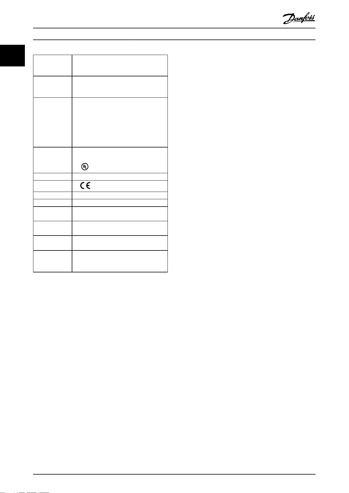
Approvals and Certications
1.5
The VLT® Integrated Servo Drive ISD® 510 System fullls
the standards listed in Table 1.2.
IEC/EN 61800-3 Adjustable speed electrical power drive
systems.
Part 3: EMC requirements and specic test
methods.
IEC/EN 61800-5-1 Adjustable speed electrical power drive
systems.
Part 5-1: Safety requirements – Electrical,
thermal, and energy.
IEC/EN 61800-5-2 Adjustable speed electrical power drive
systems.
Part 5-2: Safety requirements – Functional.
IEC/EN 61508 Functional safety of electrical/electronical/
programmable electronic safety-related
systems.
EN ISO 13849-1 Safety of machinery – Safety-related parts of
control systems.
Part 1: General principles for design.
EN ISO 13849-2 Safety of machinery – Safety-related parts of
control systems.
Part 2: Validation.
MG36C102 Danfoss A/S © 08/2017 All rights reserved. 7
Introduction
VLT® Integrated Servo Drive ISD® 510 System
11
IEC/EN 60204-1 Safety of machinery – Electrical equipment of
machines.
Part 1: General requirements.
IEC/EN 62061 Safety of machinery – Functional safety of
safety-related electrical, electronic, and
programmable electronic control systems.
IEC/EN 61326-3-1 Electrical equipment for measurement,
control, and laboratory use – EMC
requirements.
Part 3-1: Immunity requirements for safetyrelated systems and for equipment intended
to perform safety-related functions (functional
safety) – General industrial applications.
UL 508C UL Standard for Safety for Power Conversion
Equipment.
1.5.2 EMC Directive
Electromagnetic compatibility (EMC) means that electromagnetic interference between apparatus does not hinder
their performance. The basic protection requirement of the
EMC Directive 2014/30/EU states that devices that generate
electromagnetic interference (EMI), or whose operation
could be aected by EMI, must be designed to limit the
generation of electromagnetic interference and must have
a suitable degree of immunity to EMI when properly
installed, maintained, and used as intended.
Devices used as standalone or as part of a system must
bear the CE mark. Systems must not be CE marked but
must comply with the basic protection requirements of the
EMC directive.
2006/42/EC Machinery Directive
CE
2014/30/EU EMC Directive
2014/35/EU Low Voltage Directive
RoHS
(2011/65/EU)
EtherCAT
Ethernet
POWERLINK
PLCopen
®
®
Restriction of hazardous substances.
Ethernet for Control Automation Technology.
Ethernet-based eldbus system.
Ethernet-based eldbus system.
®
Technical specication.
Function blocks for motion control (formerly
Part 1 and Part 2) Version 2.0 March 17, 2011.
1.5.3 Machinery Directive
The VLT® Integrated Servo Drive ISD® 510 System
components are
subject to the Low Voltage Directive, however components
or systems with an integrated safety function must comply
with the machinery directive 2006/42/EC. Components or
systems without a safety function do not fall under the
machinery directive. If components are integrated into a
machinery system, Danfoss provides information on safety
aspects relating to them.
Machinery Directive 2006/42/EC covers a machine
classied as electronic components
consisting of an aggregate of interconnected components
Table 1.2 Approvals and Certications
or devices, of which at least 1 is capable of mechanical
movement. The directive mandates that the equipment
1.5.1 Low Voltage Directive
design must ensure the safety and health of people and
livestock are not endangered and the preservation of
The VLT® Integrated Servo Drive ISD® 510 System
components are classied as electronic components and
material worth so long as the equipment is properly
installed, maintained, and used as intended.
must be CE labeled in accordance with the Low Voltage
Directive. The directive applies to all electrical equipment
in the 50–1000 V AC and the 75–1600 V DC voltage
ranges.
When servo system components are used in machines with
at least 1 moving part, the machine manufacturer must
provide a declaration stating compliance with all relevant
statutes and safety measures. Danfoss CE-labels comply
The directive mandates that the equipment design must
ensure the safety and health of people and livestock are
not endangered and the preservation of material worth so
with the machinery directive for drives with an integrated
safety function. Danfoss provides a declaration of
conformity on request.
long as the equipment is properly installed, maintained,
and used as intended. Danfoss CE-labels comply with the
Low Voltage Directive. Danfoss provides a declaration of
conformity on request.
8 Danfoss A/S © 08/2017 All rights reserved. MG36C102
Introduction Design Guide
1.6 Safety
The following symbols are used in this guide:
WARNING
Indicates a potentially hazardous situation that could
result in death or serious injury.
CAUTION
Indicates a potentially hazardous situation that could
result in minor or moderate injury. It can also be used to
alert against unsafe practices.
NOTICE
Indicates important information, including situations that
can result in damage to equipment or property.
The following safety instructions and precautions relate to
the VLT® Integrated Servo Drive ISD® 510 System.
Read the safety instructions carefully before starting to
work in any way with the ISD 510 servo system or its
components.
Pay particular attention to the safety instructions in the
relevant sections of this manual.
WARNING
HAZARDOUS SITUATION
If the servo drive, SAB, or the bus lines are incorrectly
connected, there is a risk of death, serious injury, or
damage to the unit.
Always comply with the instructions in this
•
manual and national and local safety
regulations.
WARNING
GROUNDING HAZARD
The ground leakage current is >3.5 mA. Improper
grounding of the ISD 510 servo system components may
result in death or serious injury.
For reasons of operator safety, ground the
•
components of the ISD 510 servo system
correctly in accordance with national or local
electrical regulations and the information in this
manual.
WARNING
HIGH VOLTAGE
The ISD 510 servo system contains components that
operate at high voltage when connected to the electrical
supply network.
A hazardous voltage is present on the servo drives and
the SAB whenever they are connected to the mains
network.
There are no indicators on the servo drive or SAB that
indicate the presence of mains supply.
Incorrect installation, commissioning, or maintenance can
lead to death or serious injury.
Installation, commissioning, and maintenance
•
must only be performed by qualied personnel.
WARNING
UNINTENDED START
The ISD 510 servo system contains servo drives and the
SAB that are connected to the electrical supply network
and can start running at any time. This may be caused
by a eldbus command, a reference signal, or clearing a
fault condition. Servo drives and all connected devices
must be in good operating condition. A decient
operating condition may lead to death, serious injury,
damage to equipment, or other material damage when
the unit is connected to the electrical supply network.
Take suitable measures to prevent unintended
•
starts.
WARNING
UNINTENDED MOVEMENT
Unintended movement may occur when parameter
changes are carried out immediately, which may result in
death, serious injury, or damage to equipment.
When changing parameters, take suitable
•
measures to ensure that unintended movement
cannot pose any danger.
1 1
MG36C102 Danfoss A/S © 08/2017 All rights reserved. 9
Introduction
VLT® Integrated Servo Drive ISD® 510 System
11
WARNING
DISCHARGE TIME
The servo drives and the SAB contain DC-link capacitors
that remain charged for some time after the mains
supply is switched o at the SAB. Failure to wait the
specied time after power has been removed before
performing service or repair work could result in death
or serious injury.
To avoid electrical shock, fully disconnect the
•
SAB from the mains and wait for at least the
time listed in Table 1.3 for the capacitors to fully
discharge before carrying out any maintenance
or repair work on the ISD 510 servo system or
its components.
Number Minimum waiting time (minutes)
0–64 servo drives 10
Table 1.3 Discharge Time
NOTICE
Never connect or disconnect the hybrid cable to or from
the servo drive when the ISD 510 servo system is
connected to mains or auxiliary supply, or when voltage
is still present. Doing so damages the electronic circuitry.
Ensure that the mains supply is disconnected and the
required discharge time for the DC-link capacitors has
elapsed before disconnecting or connecting the hybrid
cables or disconnecting cables from the SAB.
NOTICE
Full safety warnings and instructions are detailed in the
VLT® Integrated Servo Drive ISD 510 System Operating
Instructions.
1.7 Terminology
VLT® Integrated
Servo Drive ISD
510
VLT® Servo Access
®
Box SAB
PLC
Loop cable Hybrid cable for connecting servo drives in
Feed-in cable Hybrid cable for connection from the SAB to
Table 1.4 Terminology
An explanation of all terminology and abbreviations can be
found in chapter 7.1 Glossary.
Integrated servo drive
Unit that generates the DC-link voltage and
passes the U
and STO signals to the servo drives via a
hybrid cable.
External device for controlling the VLT
Integrated Servo Drive ISD® 510 System.
daisy-chain format.
the 1st servo drive.
, Real-Time Ethernet, UDC,
AUX
®
10 Danfoss A/S © 08/2017 All rights reserved. MG36C102
1
2
130BE385.10
System Overview Design Guide
2 System Overview
2.1 General Description of the Servo System
2.2
VLT® Integrated Servo Drive ISD® 510
2 2
The VLT® Integrated Servo Drive ISD® 510 System is a highperformance decentral servo motion solution.
It comprises:
A central power supply: VLT® Servo Access Box
•
(SAB®).
VLT® Integrated Servo Drives ISD® 510.
•
Cabling infrastructure.
•
The decentralization of the drive unit
mounting, installation, and operation. Depending on the
application, the SAB can power up to 64 servo drives in a
servo drive system when using 2 hybrid lines. It generates
a DC-link voltage of 565–680 V DC ±10% and guarantees
high power density. It has a removable local control panel
(LCP), and is based on the proven quality of a Danfoss
frequency converter.
The motion control is integrated into the servo drive so
that the motion sequences can take place independently.
This reduces the required computing power of the central
PLC and oers a highly exible drive concept. Danfoss
oers libraries for various IEC 61131-3 programmable PLCs.
Due to the standardized and certied eldbus interfaces of
the ISD devices, any PLC with an EtherCAT® master
functionality, or Ethernet POWERLINK® managing node
functionality according to the standards can be used.
Hybrid cables are used to connect the servo drives, making
installation fast and simple. These hybrid cables contain
the DC-link supply, the Real-Time Ethernet, U
signals.
oers benets in
, and STO
AUX
ISD is the abbreviation of integrated servo drive, which is a
compact drive with an integrated permanent magnet
synchronous motor (PMSM). This means that the entire
power drive system consisting of motor, position sensor,
mechanical brake, and also power and control electronics
is integrated into 1 housing. Additional circuits, such as low
voltage supply, bus drivers, and functional safety are
implemented within the servo drive electronics. All servo
drives have 2 hybrid connectors (M23) that connect power
and communication signals from a hybrid cable. The
advanced version has 3 additional interfaces for external
encoder or I/Os, eldbus devices, and for the local control
panel (LCP) to be connected directly.
LEDs on the top of the servo drive show the current status.
Data transfer takes place via Real-Time Ethernet.
NOTICE
The ISD 510 servo drives cannot be used in servo
systems from other manufacturers without changing the
cabling infrastructure. Contact Danfoss for further
information.
Drives from other manufacturers cannot be used in the
ISD 510 servo system when using Danfoss hybrid cables.
NOTICE
Only the components described in this manual may be
tted or installed. Third-party devices and equipment
may be used only in consultation with Danfoss.
MG36C102 Danfoss A/S © 08/2017 All rights reserved. 11
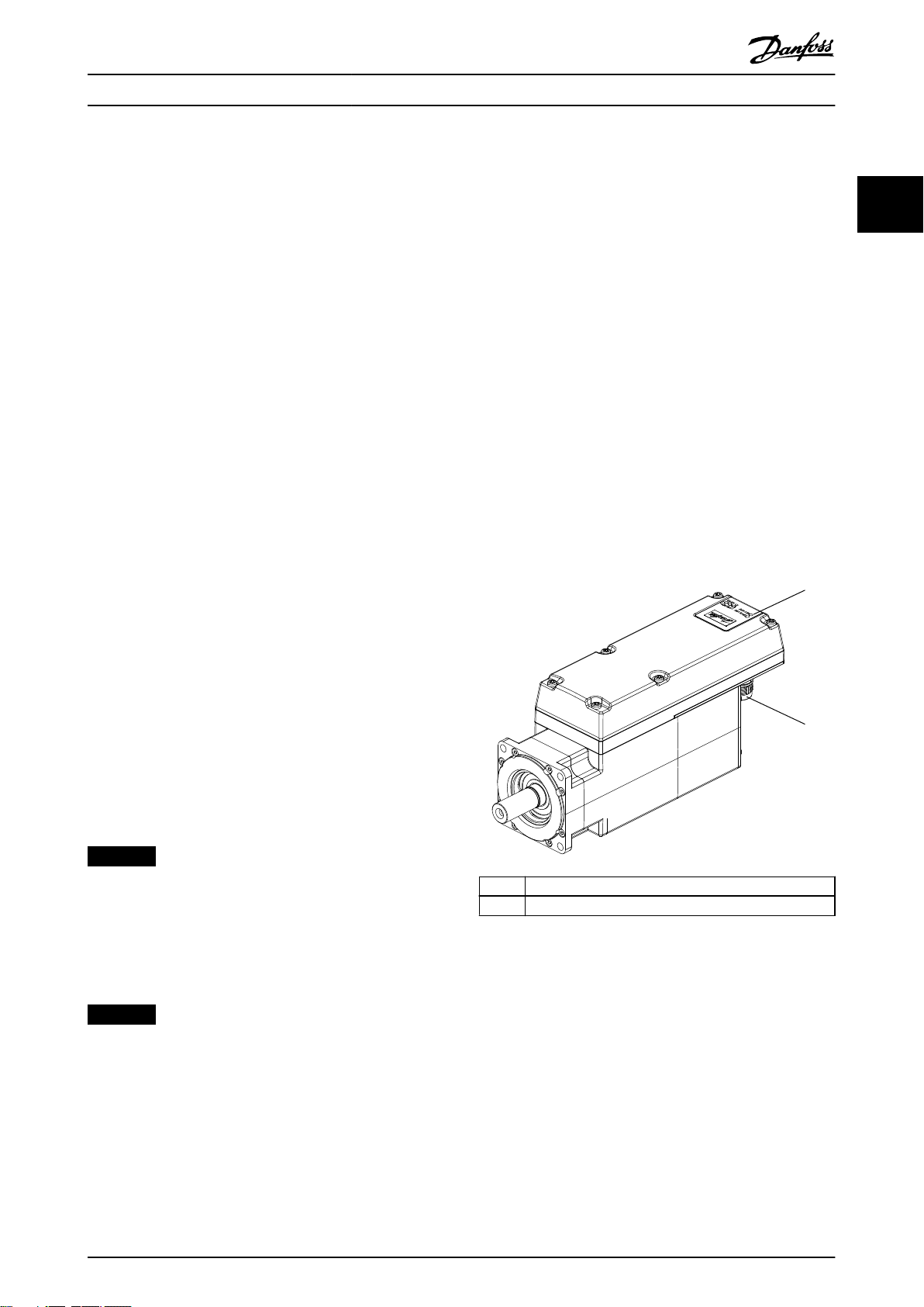
1 Operating LEDs
2 Connectors
Illustration 2.1 ISD 510 Servo Drive
Illustration 2.1 and Table 2.1 show the external interfaces on
the ISD 510 servo drive.
130BE436.10
AUX 1
Status
Hand
On
Reset
Auto
On
OK
Back
Cancel
Info
Quick
Menu
Main
Menu
Alarm
Log
AUX 2
SAFE 1
SAFE 2
Status
Hand
On
Reset
Auto
On
OK
Back
Cancel
Info
Quick
Menu
Main
Menu
Alarm
Log
LCP
SAB
400-480 V AC
Real-Time Ethernet
1
ISD 510
2
. . .
130BE437.10
AUX 1
Status
Hand
On
Reset
Auto
On
OK
Back
Cancel
Info
Quick
Menu
Main
Menu
Alarm
Log
AUX 2
SAFE 1
SAFE 2
Status
Hand
On
Reset
Auto
On
OK
Back
Cancel
Info
Quick
Menu
Main
Menu
Alarm
Log
LCP
SAB
400-480 V AC
Real-Time Ethernet
1
ISD 510
2
. . .
. . .
System Overview
VLT® Integrated Servo Drive ISD® 510 System
Interface Description
Shaft Mechanical interface.
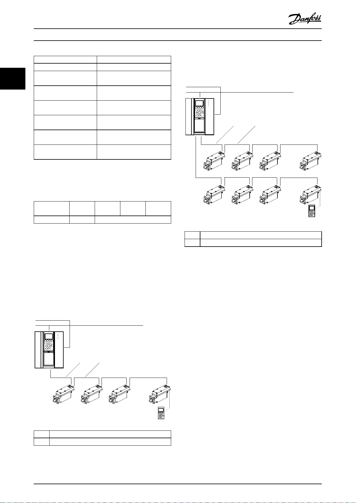
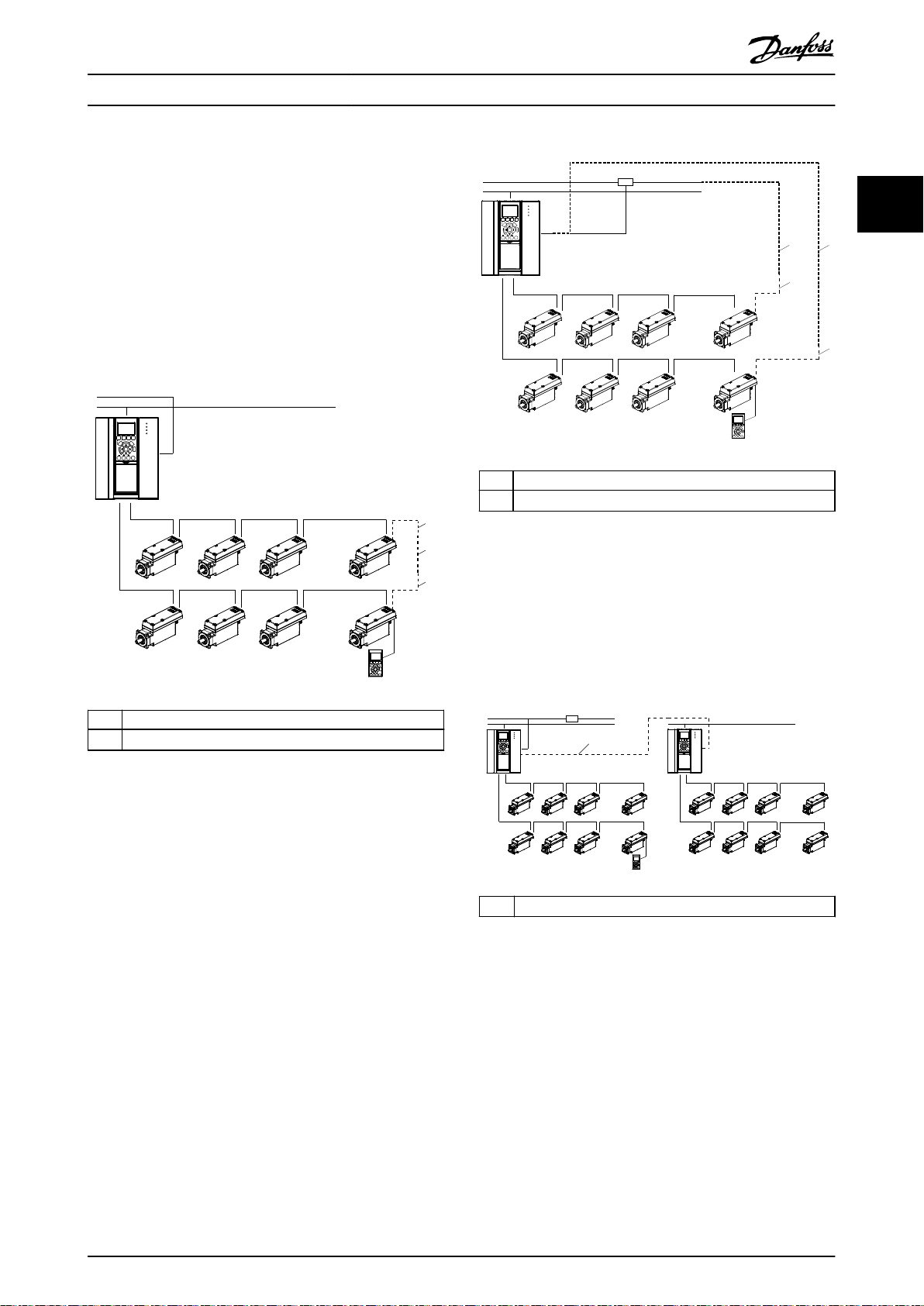
2.3.1.2 Standard Cabling Concept for 2
Lines
Operating LEDs Provides the status of the servo
22
drive.
M23 hybrid input connector Input connector for power and
communication signals.
M23 hybrid output
connector
M8 4-pole connector
(advanced servo drive only)
M12 8-pole connector
(advanced servo drive only)
M8 6-pole connector
Output connector for power and
communication signals.
Input connector for eldbus
devices.
Input connector for external
encoder or I/Os.
Input connector for LCP.
(advanced servo drive only)
Table 2.1 External Interfaces on the ISD 510 Servo Drive
The ISD 510 servo drive has the ange sizes shown in
Table 2.2.
Size 1,
1.5 Nm
Flange size 76 mm 84 mm
Table 2.2 Motor and Flange Sizes
All dimensions of the servo drive are listed in
chapter 6.1.1 Dimensions.
System Wiring
2.3
Size 2,
2.1 Nm
Size 2,
2.9 Nm
Size 2,
3.8 Nm
1 M23 Feed-in cable
2 M23 Loop cable
Illustration 2.3 Standard Cabling Concept for 2 Lines
2.3.1
Ethernet POWERLINK® without
Redundancy
2.3.1.1 Standard Cabling Concept for 1 Line
1 M23 Feed-in cable
2 M23 Loop cable
Illustration 2.2 Standard Cabling Concept for 1 Line
12 Danfoss A/S © 08/2017 All rights reserved. MG36C102
AUX 1
Status
Hand
On
Off
Reset
Auto
On
OK
Back
Cancel
Info
Quick
Menu
Main
Menu
Alarm
Log
AUX 2
SAFE 1
SAFE 2
Status
Hand
On
Off Reset
Auto
On
OK
Back
Cancel
Info
Quick
Menu
Main
Menu
Alarm
Log
LCP
SAB
400-480 V AC
ISD 510
UDC + Real-Time Ethernet Bus + STO + U
AUX
. . .
. . .
130BF040.10
Real-Time Ethernet
A
B
A
AUX 1
Status
Hand
On
Off
Reset
Auto
On
OK
Back
Cancel
Info
Quick
Menu
Main
Menu
Alarm
Log
AUX 2
SAFE 1
SAFE 2
Status
Hand
On
Off Reset
Auto
On
OK
Back
Cancel
Info
Quick
Menu
Main
Menu
Alarm
Log
LCP
SAB
400-480 V AC
ISD 510
. . .
. . .
130BF041.10
Real-Time Ethernet
A
A
B
B
PLC
UDC + Real-Time Ethernet Bus + STO + U
AUX
130BF042.10
AUX 1
Status
Hand
On
Off
Reset
Auto
On
OK
Back
Cancel
Info
Quick
Menu
Main
Menu
Alarm
Log
AUX 2
SAFE 1
SAFE 2
Status
Hand
On
Off Reset
Auto
On
OK
Back
Cancel
Info
Quick
Menu
Main
Menu
Alarm
Log
LCP
SAB
400-480 V AC
ISD 510
UDC + Real-Time Ethernet Bus + STO + U
AUX
. . .
. . .
Real-Time Ethernet
PLC
AUX 1
Status
Hand
On
Off
Reset
Auto
On
OK
Back
Cancel
Info
Quick
Menu
Main
Menu
Alarm
Log
AUX 2
SAFE 1
SAFE 2
SAB
400-480 V AC
ISD 510
UDC + Real-Time Ethernet Bus + STO + U
AUX
. . .
. . .
Real-Time Ethernet
A
System Overview Design Guide
2.3.2
Ethernet POWERLINK® with
Redundancy
There are 2 methods to use Ethernet POWERLINK® with
redundancy:
eldbus extension cable
Via a
•
Via the PLC
•
Illustration 2.4 shows Ethernet POWERLINK® with
redundancy via a eldbus extension cable.
A Fieldbus extension cable
B
3rd party network cable
2 2
A Fieldbus extension cable
B
3rd party network cable
Illustration 2.4 Ethernet POWERLINK® with Redundancy via
Fieldbus Extension Cable
Illustration 2.5 shows Ethernet POWERLINK® with
redundancy via the PLC.
Illustration 2.5 Ethernet POWERLINK® with Redundancy via
PLC
2.3.3 Wiring with more than 1 SAB
Illustration 2.6 shows how to wire the servo system using
>1 SAB.
A
3rd party network cable
Illustration 2.6 Wiring with >1 SAB
MG36C102 Danfoss A/S © 08/2017 All rights reserved. 13
2.3.3.1
To connect additional SAB units in the same Ethernet
POWERLINK® network, use an RJ45 to RJ45 network cable
from the Ethernet X2 connection on the 1st SAB to the
Ethernet X1 connection on the 2nd SAB, and so on.
Ethernet POWERLINK
®
AUX 1
Status
Hand
On
Off
Reset
Auto
On
OK
Back
Cancel
Info
Quick
Menu
Main
Menu
Alarm
Log
AUX 2
SAFE 1
SAFE 2
Status
Hand
On
Off Reset
Auto
On
OK
Back
Cancel
Info
Quick
Menu
Main
Menu
Alarm
Log
LCP
SAB
400-480 V AC
ISD 510
. . .
. . .
130BF043.10
Real-Time Ethernet
PLC
Power
CH. 1
CH. 2
P1
A2 14 24
P2
S11 S12 S21 S22
A1 13 28
P1
S33 S34 Y36 Y37
P2
PNOZ X2P
QUINT POWER
1
2
3
5
4
UDC + Real-Time Ethernet Bus + STO + U
AUX
2
System Overview
VLT® Integrated Servo Drive ISD® 510 System
2.3.3.2
22
To connect additional SAB units in the same EtherCAT
network, use an RJ45 to RJ45 network cable from the
EtherCAT
®
®
Ethernet X2 connection on the 1st SAB to the Ethernet X1
connection on the 2nd SAB, and so on.
2.4
EtherCAT® with Redundancy
Component Description
ISD 510 servo
drive
Motors with integrated signal and power
electronics. They are mounted decentrally in the
application and have advanced motion control
functionality on board.
Servo Access
Box (SAB)
Central supply and access unit for mounting
inside a control cabinet. The SAB is the power
supply for the ISD 510 servo drives and is the
central access point for the eldbus.
Ring redundancy can be achieved using a special cabling
scheme. Connect the eldbus extension cable to the last
servo drive on the line and connect the other end of the
cable with an Ethernet CAT5 cable. Settings must also be
made in the engineering environment; see the
corresponding online help for further information.
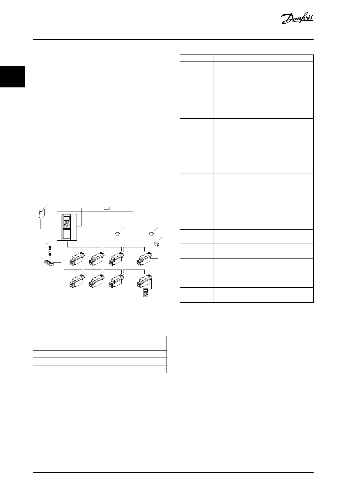
2.5 Description of Operation
Illustration 2.7 shows the VLT® Integrated Servo Drive
ISD® 510 System and components.
Hybrid cable There are 2 types of hybrid cable:
Feed-in cable: Connects the SAB to the 1
•
servo drive.
Loop cable: Connects the servo drives in an
•
application in daisy-chain format. Speed
connectors minimize installation time, cost,
and risk of failures.
Local Control
Panel (LCP)
Graphical user interface for diagnostic and
operating purposes. The LCP is mounted on the
SAB but can be removed and connected to the
st
servo drive via connector X5 (advanced version
only). The LCP can be used for the ID
assignment of the advanced servo drives. The ID
assignment is started via LCP and the LCP also
indicates if the procedure is nished.
External
encoder
PLC
An external encoder can be connected to each
SAB and servo drive in the system.
PLC with Ethernet POWERLINK® and EtherCAT
®
eldbus master functionality.
STO Safe torque o feature can be provided via
external safety circuits.
Analog/Digital
Connection to the servo drives is possible.
Sensor
3rd party
eldbus device
Connection to the M8 4-pole eldbus port on
the servo drive (advanced servo drive only)
Illustration 2.7 Overview of the ISD 510 Servo System and
Table 2.4 ISD 510 System Components
Components
1 24/48 V power supply
2 Encoder
3 I/O
4 Brake resistor
5
Safety relay
1)
Table 2.3 Legend to Illustration 2.7
1) Safety relays that have a plus and minus switching output signal
can be directly connected to the ISD 510 servo system to activate
STO.
14 Danfoss A/S © 08/2017 All rights reserved. MG36C102
1
2
54
6
8
7
3
Ethernet X1
Ethernet X2
AC mains supply
24/48 V IN
STO 1 IN: STO 1 ISD Line 1: STO 1
ISD Line 2: STO 2
ISD Line 2: AUX 2
ISD Line 1: AUX 1
ISD Line 2: UDC 2
ISD Line 1: UDC 1
Ethernet X4
Ethernet X3
STO 2 IN: STO 2
130BF744.10
1
2 3
4
5
6 7 8
STO+
STO–
UDC+
UDC–
AUX+
AUX–
Advanced
servo drive
Ethernet
130BF743.10
System Overview Design Guide
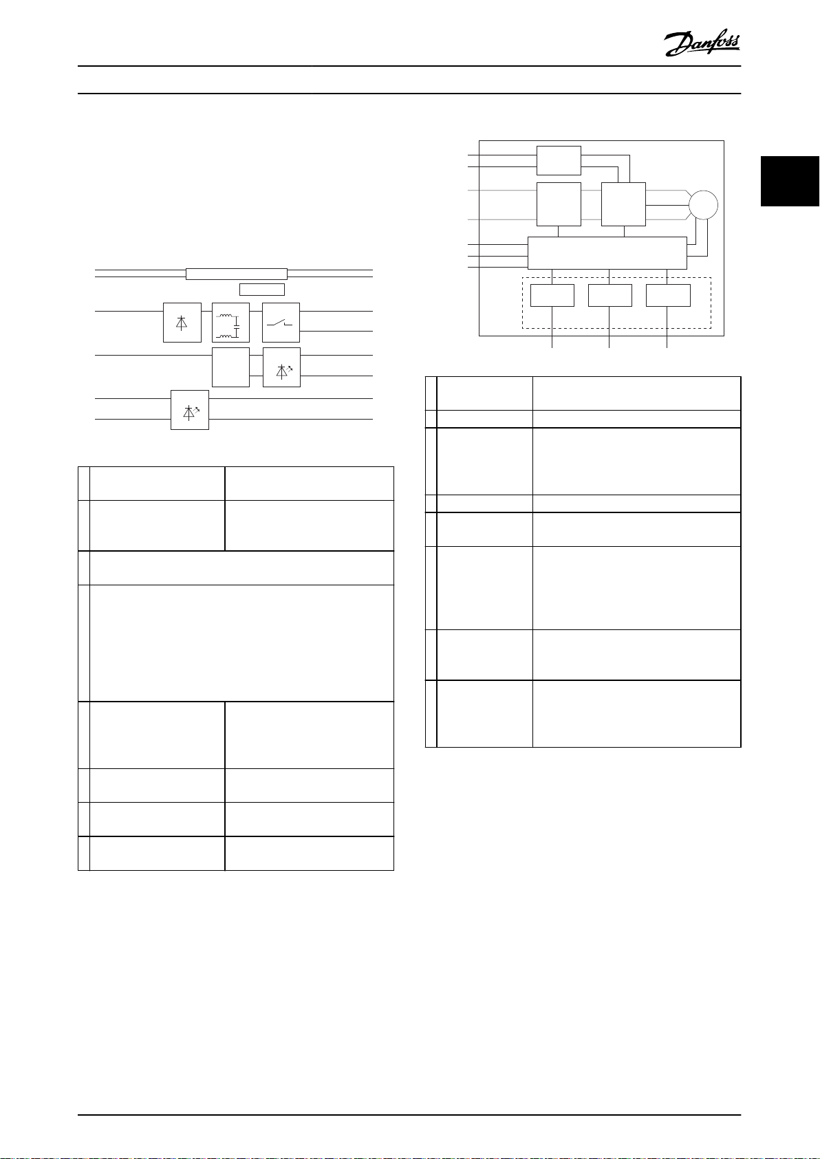
2.6 Sequence of Operation
2.6.1
VLT® Servo Access Box (SAB)
Illustration 2.8 shows a simplied block diagram of the SAB.
1 Control logic Used for communication and
monitors the status of the SAB.
2 SMPS (Switch mode power
supply)
3 When power is rst applied to the SAB, it enters through the
input terminals (L1, L2, and L3) and on to the RFI lter.
4 Following the rectier section, voltage passes to the
intermediate section. This rectied voltage is smoothed by a
sine-wave lter circuit, consisting of the DC bus inductor and
the DC bus capacitor bank. The DC bus inductor provides
series impedance to changing current. This aids the ltering
process while reducing harmonic distortion to the input AC
current waveform normally inherent in rectier circuits.
5 Switch For enabling or disabling the UDC
6 Overvoltage/overcurrent
protection
7 LED indicators Show the presence of the AUX
8 LED indicators Show the presence of the STO
Used to generate the control
voltage from the intermediate
bus.
output lines. Inrush current
limitation for the servo drives is
also done within this section.
For the auxiliary line.
voltage at the outputs of the SAB.
voltage.
1 STO circuit If STO is activated, the STO circuit disables
the inverter.
2 DC bus and lter The DC bus and lter smooth the voltage.
3 Inverter In the inverter section, once run
command and speed/position references
are present, the IGBTs begin switching to
create the output waveform.
4 Motor Synchronous permanent magnet motor.
5 Control circuit Used for generating the PWM pattern and
monitoring the status of the ISD.
6 X4: M12 I/O
and/or encoder
connector
(advanced servo
drive only)
7 X5: LCP connector
(advanced servo
drive only)
8 X3: Ethernet
connector
(advanced servo
drive only)
Illustration 2.9 Simplied Block Diagram of the ISD 510 Servo
Drive
2.6.3
Switching on the VLT® Integrated
This interface can be used to connect
digital inputs/outputs. It can also be used
for analog values. SSI/BISS encoders can
be connected to this interface.
An LCP can be connected to read out
parameters and set-up of the servo drive.
This interface can be used to connect
external real-time Ethernet devices.
Servo Drive ISD 510 System
2 2
Illustration 2.8 Simplied Block Diagram of the Servo Access
Box
2.6.2
Table 2.1 shows a simplied block diagram of the ISD 510
servo drive.
MG36C102 Danfoss A/S © 08/2017 All rights reserved. 15
VLT® Integrated Servo Drive ISD 510
The cabling in the ISD 510 servo system provides the
supply voltage and the communication signals. This is a
fundamental requirement for operation of the servo drives.
The ISD 510 servo system can be switched on in 3 ways:
If the SAB is supplied with mains and U
•
AUX
,
communication to the SAB internal controller is
established and U
is automatically passed on
AUX
to the connected servo drives.
If the SAB is only powered by U
•
, then the SAB
AUX
and servo drive control units are running.
System Overview
VLT® Integrated Servo Drive ISD® 510 System
If the SAB is only supplied with mains power,
•
then only the SAB control unit is running and
power is not passed on to the connected servo
22
drives.
Procedure for switching on the ISD 510 servo system
1. Switch U
power on to enable communication
AUX
to the SAB and servo drives.
2. Switch the mains on.
3. Set the SAB to state Operation Enabled.
4. The SAB and servo drives are now ready for
operation.
2.7 Functional Safety Concept
2.7.1 Notes
Use of the STO function requires that all provisions for
safety, including relevant laws, regulations, and guidelines,
are satised.
The integrated STO function complies with the following
standards:
EN 60204-1: 2006 Stop Category 0 – uncontrolled
•
stop
IEC/EN 61508: 2010 SIL 2
•
IEC/EN 61800-5-2: 2007 SIL 2
•
IEC/EN 62061: 2005 SIL CL2
•
EN ISO 13849-1: 2015
•
The VLT® Integrated Servo Drive ISD 510 System has been
Abbreviation Reference Description
PFH EN IEC 61508 Probability of dangerous failures
per hour
Take this value into account if the
safety device is operated in high
demand mode or in continuous
operating mode, where the
frequency of demands for
operation made on a safety-related
system occurs more than once per
year.
PFD EN IEC 61508 Average probability of failure on
demand
This value is used for low demand
operation.
PL EN ISO
13849-1
SFF EN IEC 61508 Safe Failure Fraction [%]
SIL EN IEC 61508
EN IEC 62061
STO EN IEC
61800-5-2
Table 2.5 Abbreviations and Conventions
Performance level
A discrete level used to specify the
capability of safety-related parts of
a system to perform safetyoriented functions under
foreseeable conditions. Levels: a–e.
Proportion of safe failures and
detected dangerous failures of a
safety function or a subsystem as a
percentage of all possible failures.
Safety Integrity Level
Safe Torque O
tested for higher EMC immunity as described in
EN 61800-5-2:2017.
2.7.3 Functional Description
2.7.2 Abbreviations and Conventions
Abbreviation Reference Description
Cat. EN ISO
13849-1
DC – Diagnostic coverage
FIT – Failure in time
HFT EN IEC 61508 Hardware fault tolerance
MTTF
D
EN ISO
13849-1
Category, level B, 1–4
Failure rate: 1E-9/hour
H = n means that n + 1 faults may
lead to a loss of the safety
function.
Mean time to failure – dangerous
Unit: years
The STO function in the VLT® Integrated Servo Drive ISD
510 System features a separate STO function for each line
of servo drives in daisy-chain format. The function is
activated by inputs on the SAB. Using the STO function
activates the STO for all servo drives on that line. Once the
STO is activated, no torque is generated on the axes. Reset
of the safety function and diagnostics can be carried out
via the PLC.
NOTICE
The ISD 510 servo system does not implement a manual
reset function as required by ISO 13849-1. The standard
failure reset from the PLC cannot be used for this
purpose.
For automatic restart without manual reset, observe the
requirements detailed in paragraph 6.3.3.2.5 of ISO
12100:2010 or equivalent standard.
16 Danfoss A/S © 08/2017 All rights reserved. MG36C102
130BE690.10
SAB
STO 1 IN: + STO
STO 1 IN: – STO
STO 2 IN: + STO
STO 2 IN: – STO
System Overview Design Guide
NOTICE
Carry out a risk assessment to select the correct stop
category for each stop function in accordance with
EN 60204-1.
NOTICE
When designing the machine application, consider
timing and distance for coast to stop (Stop Category 2 or
STO). See EN 60204-1 for further information.
NOTICE
All signals connected to the STO must be supplied by a
SELV or PELV supply.
2.7.4 Installation
Only Danfoss cables may be used for the installation of the
servo system, however cables from other suppliers may be
used for the user connection to the STO terminals (STO 1
IN and STO 2 IN) on the SAB.
NOTICE
If the application does not require the Safe Torque O
(STO) functionality, build a bridge by connecting +24 V
from the connector STO 1 IN: +24V to STO 1 IN: +STO,
and from STO 1 IN: –24 V to STO 1 IN: –STO. Repeat this
process for STO line 2 if used.
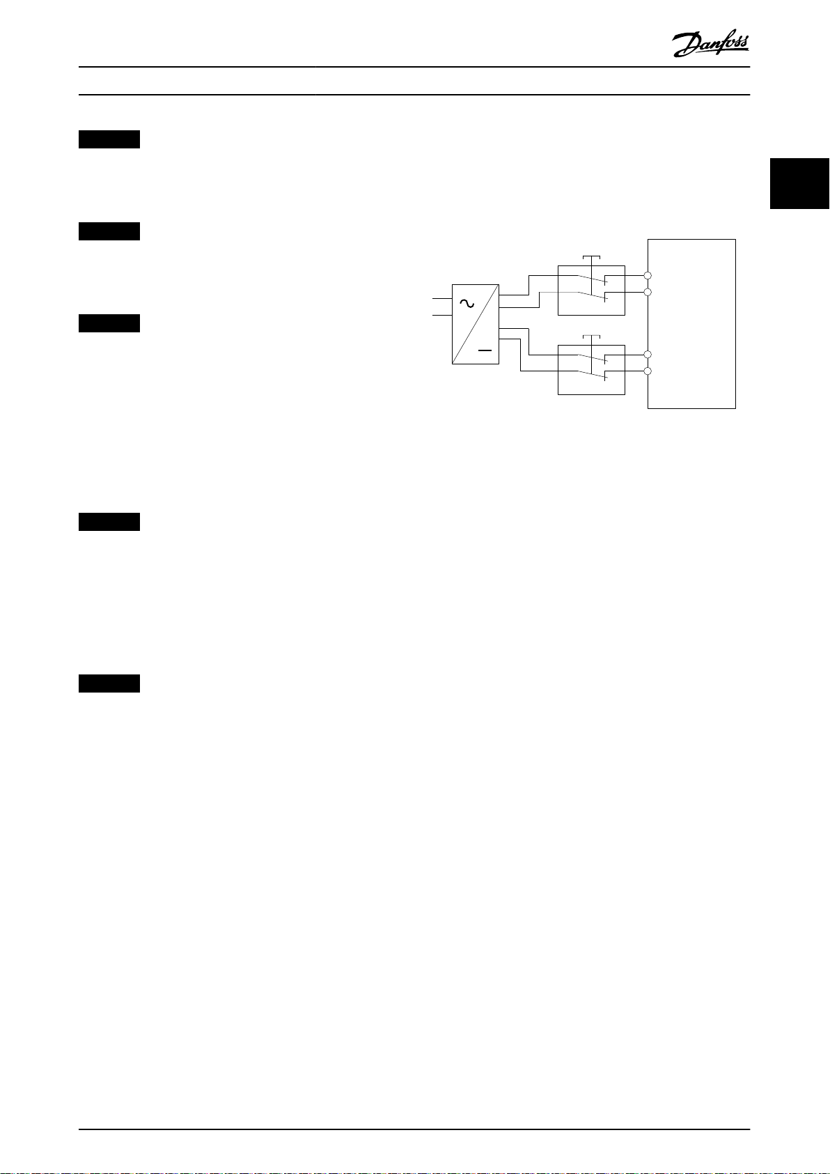
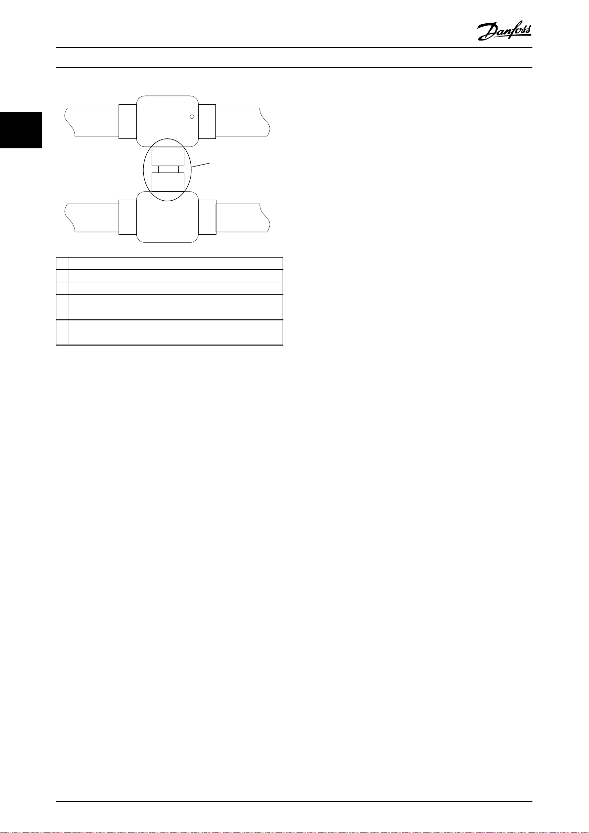
Safety relays that have a plus and minus switching output
signal can be directly connected to the VLT® Integrated
Servo Drive ISD 510 System to activate STO (see
Illustration 2.10). Route the wires for STO 1 and STO 2
separately and not in a single multicore cable.
Illustration 2.10 Safety Relay with Plus and Minus Switching
Output
Signals with test pulses must not have test pulses of >1
ms. Longer pulses may lead to reduced availability of the
servo system.
2 2
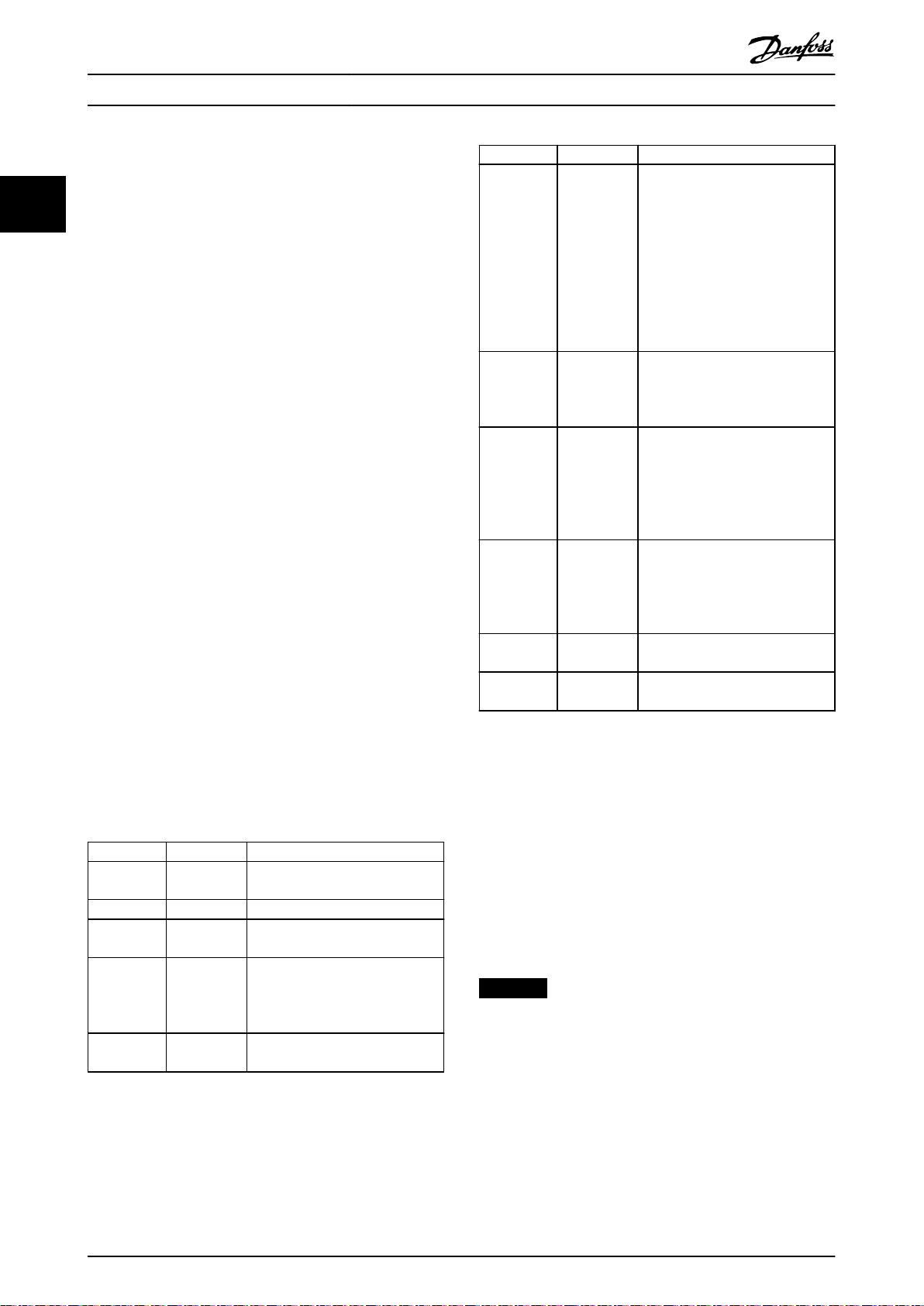
2.7.5 Commissioning Test
NOTICE
Perform a commissioning test after installation of the STO function, after every change to the installed function, or after
a safety fault. Perform the test for each STO line.
There are 2 ways to implement the commissioning test depending on the method used to program the PLC, however the
steps of the test are the same:
Using the Danfoss Library or the TwinCAT® Library.
•
Bit-wise readout of the status.
•
Commissioning test using libraries
Depending on the application, 1 or both of the following libraries are required to program the commissioning test:
Danfoss Library
•
- MC_ReadAxisInfo_ISD51x
- MC_ReadStatus_ISD51x
- MC_ReadAxisError_ISD51x
- MC_Reset_ISD51x
TwinCAT® Library
•
- MC_ReadStatus
- MC_ReadAxisError
- MC_Reset
MG36C102 Danfoss A/S © 08/2017 All rights reserved. 17

System Overview
VLT® Integrated Servo Drive ISD® 510 System
Test steps Reason for the test step Expected result for Danfoss
library
22
1 Run the application (all the
servo drives are enabled).
2 Stop the application. – All servo drives are at speed 0
3 Disable all the servo drives. – All servo drives are disabled. All servo drives are disabled.
4 Enable STO. Check that STO can be
5 Disable STO. Check that STO can be
6 Run the application (all the
servo drives are enabled).
7 Enable STO. Check that errors are
8 Try to run the application
(enable 1 or more servo
drives).
9 Disable STO. Check that the STO start is
10 Try to run the application
(enable 1 or more servo
drives).
11 Send a reset signal via
MC_Reset(_ISD51x).
12 Try to run the application (all
servo drives are enabled).
Check that the application can
run.
activated without error.
deactivated without error. No
reset is required.
– Application runs as expected. Application runs as expected.
generated correctly when STO
is activated while the servo
drives are running.
Checks that the STO function
is working correctly.
still inhibited by the error
signal.
Check whether reset is
required.
– MC_ReadAxisInfo_ISD51x output
– Application runs as expected. Application runs as expected.
Application runs as expected. Application runs as expected.
RPM.
MC_ReadAxisInfo_ISD51x output
SafeTorqueO = True for all
servo drives on the
corresponding line.
MC_ReadAxisInfo_ISD51x output
SafeTorqueO = False for all
servo drives on the
corresponding line.
Motors are torque free. Motors
coast and stop after some
time.
MC_ReadAxisInfo_ISD51x output
SafeTorqueO = True
and
MC_ReadStatus_ISD51x output
ErrorStop = True
and
MC_ReadAxisError_ISD51x
output AxisErrorID = 0xFF80 on
all enabled servo drives.
Application does not run. Application does not run.
MC_ReadAxisInfo_ISD51x output
SafeTorqueO = False
and
MC_ReadStatus_ISD51x output
ErrorStop = True
Application does not run. Application does not run.
SafeTorqueO = False
and
MC_ReadStatus_ISD51x output
ErrorStop = False
Expected result for TwinCAT
library
All servo drives are at speed 0
RPM.
–
–
Motors are torque free. Motors
coast and stop after some
time.
For enabled motors:
MC_ReadStatus output ErrorStop
= True
and
MC_ReadAxisError output
AxisErrorID = 0xFF80 on all
enabled servo drives.
MC_ReadStatus output ErrorStop
= True
MC_ReadStatus output ErrorStop
= False
®
Table 2.6 Commissioning Test using Libraries
18 Danfoss A/S © 08/2017 All rights reserved. MG36C102
System Overview Design Guide
Commissioning test using bit-wise readout
Test steps Reason for the test step Expected result
1 Run the application (all the servo drives
are enabled).
2 Stop the application. – All servo drives are at speed 0 RPM.
3 Disable all the servo drives. – All servo drives are disabled.
4 Enable STO. Check that STO can be activated without
5 Disable STO. Check that STO can be deactivated
6 Run the application (all the servo drives
are enabled).
7 Enable STO. Check that errors are generated correctly
8 Try to run the application (enable 1 or
more servo drives).
9 Disable STO. Check that the STO start is still inhibited
10 Try to run the application (enable 1 or
more servo drives).
11 Send a reset signal via the PLC. – Statusword bit 3 = 0 in all servo drives.
12 Try to run the application (all servo drives
are enabled).
Check that the application can run. Application runs as expected.
Statusword bit 3 = 0 and bit 14 =1 in all
error.
without error. No reset is required.
– Application runs as expected.
when STO is activated while the servo
drives are running.
Checks that the STO function is working
correctly.
by the error signal.
Check whether reset is required. Application does not run.
– Application runs as expected.
servo drives.
Statusword bit 3 = 0 and bit 14 =0 in all
servo drives.
Motors are torque free. Motors coast and
stop after some time.
Statusword bit 3 = 1, bit 14 = 1 and
object 0x603F shows fault 0xFF80 in all
servo drives.
Application does not run.
Statusword bit 3 = 1, bit 14 = 0 and
object 0x603F shows fault 0xFF80 in all
servo drives.
2 2
Table 2.7 Commissioning Test using Bit-Wise Readout
MG36C102 Danfoss A/S © 08/2017 All rights reserved. 19
+24 V DC
GND
130BE689.11
8a
8b
9a
9b
4
2
3
1
X1
X2
X1
X2
X1
X2
X1
X2
6
6
7
5
System Overview
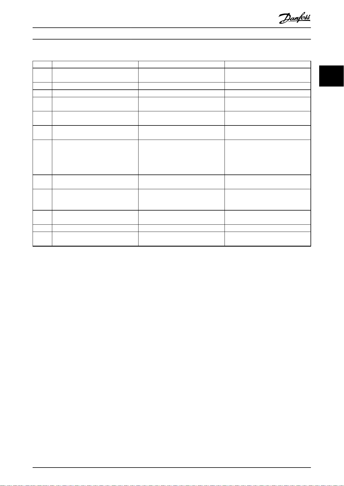
2.7.6 Application Example
VLT® Integrated Servo Drive ISD® 510 System
22
Illustration 2.11 shows an example of an installation for 2 lines that can be put in Safe Torque O mode by separate safety
circuits for each line.
The safety circuits may be remote from each other and are not supplied from the VLT® Integrated Servo Drive ISD 510
System.
The 2 lines in the example are controlled separately. If the Safe Torque
normal operation and the servo drives on this line are not aected. There may still be a hazard from the servo drives on
line 2.
Select the safety switch devices in accordance with the requirements of the application.
O function is triggered on line 1, line 2 remains in
1a/1b ISD 510 servo drive on line 1 8 Line 2 emergency stop button
2a/2b ISD 510 servo drive on line 2 9 Line 2 safety device contacts
3 Servo Access Box (SAB) 10 Line 1 hybrid cable
4 Safety device on line 1 11 Line 2 hybrid cable
5 Line 1 emergency stop button 12 Feed-in cable
6 Line 1 safety device contacts 13 Loop cable
7 Safety device on line 2 14 24 V DC supply
Illustration 2.11 Application Example: Safe Torque O Function with 2 Lines
20 Danfoss A/S © 08/2017 All rights reserved. MG36C102
EtherCAT
Slave Controller
(ESC)
OUT
Port 1 (B)
OUT
Port 2 (C)
IN
Port 0 (A)
X2X1
X3
130BE695.10
System Overview Design Guide
2.7.7 Safety Function Characteristic Data
General information
Response time (from switching on the
input until torque generation is
disabled)
Lifetime 20 years
Data for EN/ISO 13849-1
Performance level (PL) d
Category 3
Mean time to dangerous failure
(MTTFd) for maximum system size of
32 servo drives on each STO line
Diagnostic coverage (DC) 60%
Data for EN/IEC 61508 and EN/IEC 62061
Safety integrity level (SIL) 2
Probability of failure per hour (PFH) for
maximum system size of 32 servo
drives on each STO line
Safe failure fraction (SFF) >95%
Hardware fault tolerance (H) 0
Subsystem classication Type A
Proof test interval 1 year
Table 2.8 Safety Function Characteristic Data
<100 ms
233 years (limited to 100
years if the VLT
Integrated Servo Drive
ISD 510 System forms an
entire safety channel)
<5 x 10⁻⁸/h
®
The servo drives and the SABs can be operated with the
following cycle times (for both eldbuses):
400 µs and multiples of it (for example, 800 µs,
•
1200 µs, and so on).
500 µs and multiples of it (for example, 500 µs,
•
1 ms, and so on).
When the cycle time is a multiple of 400 µs and 500 µs,
the time base of 500 µs is used.
The servo drive and the SAB are certied for both
eldbuses according to the corresponding rules and
regulations. The servo drive conforms to the CANopen
CiA DS 402 Drive
2.8.1.1
EtherCAT
Prole.
®
®
The servo drive and the SAB support the following
EtherCAT® protocols:
CANopen over EtherCAT® (CoE)
•
File Access over EtherCAT® (FoE)
•
Ethernet over EtherCAT® (EoE)
•
The servo drive and the SAB support distributed clocks. To
compensate for the failure of a communication cable
section in the system, cable redundancy is available for
both eldbuses.
2 2
Communication
2.8
2.8.1 Fieldbus
The VLT® Integrated Servo Drive ISD 510 System has an
open system architecture realized by fast Ethernet
(100BASE-T) based communication. The system supports
both EtherCAT® and Ethernet POWERLINK® eldbuses. See
the VLT® Integrated Servo Drive ISD® 510 System
Programming Guide for further information.
In productive environments, communication to the devices
always takes place via a PLC that acts as a master. The
servo drives and the SABs can be controlled by these
communication methods:
Using the Danfoss VLT® Servo Motion library
•
(available for TwinCAT® and Automation
Studio™).
Using the NC axis functionality of TwinCAT® for
•
the servo drives.
Using the CANopen® CiA DS 402 standard by
•
reading and writing to objects.
The EtherCAT® port assignment for the servo drive and
SAB is shown in Illustration 2.12 and Illustration 2.13.
X1 M23 hybrid cable connector to SAB or previous servo drive.
X2 M23 hybrid cable connector to the next servo drive.
X3
M8 Ethernet cable connector to other EtherCAT® slaves, for
example EtherCAT® encoder.
The connector is only available on the advanced servo drive.
Illustration 2.12 EtherCAT® Port Assignment for the ISD 510
Servo Drive
MG36C102 Danfoss A/S © 08/2017 All rights reserved. 21
ESC SAB L1
Main EtherCAT
slave
OUT
Port 2 (C)
OUT
Port 1 (B)
IN
Port 0 (A)
X1
ESC SAB L2
AL emulated
junction slave
IN
Port 0 (A)
OUT
Port 1 (B)
OUT
Port 2 (C)
X2
X3
X4
1
R
130BE696.10
System Overview
22
VLT® Integrated Servo Drive ISD® 510 System
CAM editor for designing CAM proles for the
•
servo drives.
The detailed description of the DDS Toolbox functionality
and the full parameter lists can be found in the VLT
Integrated Servo Drive ISD® 510 System Programming Guide.
®
2.8.2.1 System Requirements
To install the DDS Toolbox software, the PC must meet the
following requirements:
Supported hardware platforms: 32-bit, 64-bit.
•
®
1 Ports always connected internally in the SAB.
X1 RJ45 cable connector to the PLC or previous slave.
X2 RJ45 cable connector to the PLC or next slave.
X3
M23 feed-in cable to the 1st servo drive on line 1 with RJ45
connector.
X4
M23 feed-in cable to the 1st servo drive on line 2 with RJ45
connector.
Illustration 2.13 EtherCAT® Port Assignment for the SAB in
Line Topology Mode (default)
Supported operating systems: Microsoft
•
Windows XP Service Pack 3, Windows 7, Windows
8.1.
.NET framework version: 3.5 Service Pack 1.
•
Minimum hardware requirements: 512 MB RAM,
•
Intel Pentium 4 with 2.6 GHz or equivalent, 40 MB
hard disk space.
Recommended hardware requirements: Minimum
•
1 GB RAM, Intel Core i5/i7 or compatible.
2.8.1.2
The servo drive and the SAB are certied according to
DS301 V1.1.0. The following features are supported for the
servo drive and the SAB:
Specic ports are not assigned for Ethernet POWERLINK®.
Ethernet POWERLINK
Work as controlled node.
•
Can be operated as multiplexed stations.
•
Support of cross-communication.
•
Ring redundancy is supported for media
•
redundancy.
®
2.8.2 PC-Software
The DDS Toolbox is a standalone PC software designed by
Danfoss. It is used for parameterization and diagnostics of
the servo drives and the SAB and can also be used to
operate the devices in a non-productive environment. The
DDS Toolbox contains several functionalities, called subtools, which in turn provide various functionalities.
The most important sub-tools are:
Scope for visualization of the tracing functionality
•
of the servo drives and SAB.
•
•
•
Parameter list for reading/writing parameters.
Firmware update
ISD 500 Drive control/SAB control to operate the
servo drives and/or SAB for testing purposes.
22 Danfoss A/S © 08/2017 All rights reserved. MG36C102

System Overview Design Guide
2.9 Operating Modes
The VLT® Integrated Servo Drive ISD 510 implements several modes of operation. The behavior of the servo drive depends
on the activated mode of operation. It is possible to switch between the modes while the servo drive is enabled. The
supported modes of operation are according to CANopen® CiA DS 402 and there are also ISD-specic modes of operation.
All supported modes of operation are available for EtherCAT® and Ethernet POWERLINK®.
The various modes of operation are described in detail in the VLT® Integrated Servo Drive ISD® 510 System Programming
Guide.
Mode Description
2 2
ISD Inertia measurement
mode
Prole velocity mode In prole velocity mode, the servo drive is operated under velocity control and executes a movement with
Prole position mode In prole position mode, the servo drive is operated under position control and executes absolute and
Prole torque mode In prole torque mode, the servo drive is operated under torque control and executes a movement with
Homing mode In homing mode, the application reference position of the servo drive can be set. Several homing methods,
CAM mode In CAM mode, the servo drive executes a synchronized movement based on a master axis. The synchroni-
Gear mode In gear mode, the servo drive executes a synchronized movement based on a master axis by using a gear
Cyclic synchronous position
mode
Cyclic synchronous velocity
mode
This mode measures the inertia of an axis. It is used to measure the inertia of the servo drive and the
external load, and to optimize the control loop settings. The friction eects are eliminated automatically.
constant speed. Additional parameters, such as acceleration and deceleration, can be parameterized.
relative movements. Additional parameters, such as velocity, acceleration, and deceleration, can be parameterized.
constant torque. Linear ramps are used. Additional parameters, such as torque ramp and maximum
velocity, can be parameterized.
such as homing on actual position, homing on block, limit switch, or home switch are available.
zation takes place by means of a CAM prole that contains slave positions corresponding to master
positions. CAMs can be designed graphically with the DDS Toolbox software, or can be parameterized via
the PLC. The guide value can be provided by an external encoder, virtual axis, or the position of another
axis.
ratio between the master and the slave position. The guide value can be provided by an external encoder,
virtual axis, or the position of another axis.
In cyclic synchronous position mode, the trajectory generator of the position is located in the control
device, not in the servo drive.
In cyclic synchronous velocity mode, the trajectory generator of the velocity is located in the control
device, not in the servo drive.
Table 2.9 Operating Modes
MG36C102 Danfoss A/S © 08/2017 All rights reserved. 23
System Overview
VLT® Integrated Servo Drive ISD® 510 System
2.10 Automated Operational Functions
2.10.1 Short Circuit Protection
22
2.10.1.1 Servo Access Box Features
The SAB has several protection functions for limiting the
current:
IN 100% (15 A
•
100–200% current is limited by an I2t function. A
•
load of 160% is allowed for 1 minute. The RMS
current must be lowered to ≤100% before a new
overload is allowed. The time taken to reset the
I2t function depends on the load current. A 2 A
overload for 10 s (17 A) requires a nominal
current of ≤13 A for 10 s to reset the I2t function.
IDC protection (UDC)
Imax0: At 200% RMS, the output will be discon-
•
nected within 1.5 s.
Imax1: At 51 A peak current, the output will be
•
disconnected within 500 μs.
Imax2: At 125 A peak current, the output will be
•
disconnected within 10 μs.
I
protection
AUX
Software limit range: 0–15 A
•
- A warning and alarm is issued at
These software limits are disabled by default. See
•
parameters AUX line 1 user current limit and AUX
line 2 user current limit in the VLT® Integrated Servo
Drive ISD 510 System Programming Guide.
A low-pass lter is implemented in the rmware
•
to avoid unintended warnings or alarms due to
inrush currents.
2.10.1.2 ISD 510 Servo Drive Features
To protect the servo drive and the machinery attached to
the servo drive shaft, a current limit protection is
implemented in the servo drive.
Current limit protection is implemented on the servo drive
and the currents are constantly monitored. If an
overcurrent occurs, an error is issued and the servo drive
coasts to stop as default. For servo drives with the
mechanical brake option, the brake engages.
), no limitation.
RMS
user-
specied levels. A warning is issued at
90% of the selected value. An alarm is
issued when the measured value has
exceeded the software limit.
2.10.2 Ground Fault Protection
When a ground fault current of >3 A is present, a warning
is issued immediately. The SAB issues an error if the
warning is present for 10 s.
2.10.3 Temperature-controlled Fans
The SAB has 2 built-in forced air convection fans to ensure
optimum cooling. The main fan forces the airow along
the cooling ns on the heat sink, ensuring cooling of the
internal air. A secondary fan cools the SAB power control
board. Both fans are controlled by the internal temperature
and speed increases. The fans not only ensure maximum
cooling when required, but also reduce noise and energy
consumption when the workload is low.
If overtemperature occurs in the SAB, an error/warning is
issued, resulting in a coast and trip lock.
2.10.4 Thermal Protection
Thermal protection exists for both the servo drive and the
SAB. See chapter 4.6.3 Thermal Protection for further
information.
2.10.5 Additional Protection Features
2.10.5.1 Servo Access Box
The SAB has the additional protection features detailed in
Table 2.10.
Function Description Limits/errors
UDC
overvoltage
UDC
undervoltage
When the DC-link
voltage rises above
a certain level, a
warning/error is
issued.
A brake resistor can
be connected to
the SAB and
activated via
parameter 0x2030 in
the DDS Toolbox
software.
When the DC-link
voltage drops
below a certain
level, a warning/
error is issued.
Brake active: >778 V
•
Warning: >810 V
•
Error: >820 V
•
Warning: <410 V
•
Error: <373 V
•
24 Danfoss A/S © 08/2017 All rights reserved. MG36C102

System Overview Design Guide
Function Description Limits/errors
AUX
overvoltage
AUX
undervoltage
AUX
overcurrent
Brake error The SAB reports
Inrush fault The SAB can handle
Mains phase
loss
STO 1 & STO
2 indicators
Table 2.10 Additional Protection Features for SAB
2.10.5.2
When the AUX
voltage rises above
a certain level, a
warning/error is
issued.
When the AUX
voltage drops
below a certain
level, a warning/
error is issued.
When the AUX
current rises above
a certain level, a
warning/error is
issued.
various brakerelated errors.
up to 2 inrush
cycles per minute.
The SAB detects
the mains phase
loss and issues a
warning/error when
limits are reached.
The SAB indicates
the presence of the
STO 1 & STO 2
voltage.
Warning: >53 V
•
Error: >56 V
•
Warning: <21.6 V
•
Error: <19 V
•
Warning: >90% of user-
•
dened limit
Error: >100% of user-
•
dened limit
The default value of
15 A is used if no limits
are dened by the user.
Shorted brake resistor
•
Shorted brake IGBT
•
Thermal overload
•
Disconnected brake
•
resistor
Error issued if >2 inrush
cycles occur per minute.
Warning: 3–10% mains
•
phase imbalance
Error:
•
- >10% mains
phase
imbalance
- 3–10% mains
phase
imbalance for
>10 minutes
LED on: STO deactivated
LED o: STO activated
VLT® Integrated Servo Drive
ISD 510
The VLT® Integrated Servo Drive ISD 510 has the additional
protection features detailed in Table 2.10.
Function Description Limits/errors
UDC
overvoltage
UDC
undervoltage
Overcurrent at
output
Motor
position
Brake control The brake current is
Maximum
shaft speed
Torque limit The application peak torque
When the DC-link voltage
rises above a certain level, a
warning/error is issued.
When the DC-link voltage
drops below a certain level, a
warning/error is issued.
To protect the servo drive
and any machinery attached
to the servo drive shaft, a
current limit protection is
implemented. The current
limit protection on the servo
drive is available for motor
phase current. All 3 phase
currents are constantly
monitored. If an overcurrent
occurs, the servo drive stops
the actual operation. The
servo drive stops the shaft
rotation, engages the brake
(if present), and an error is
issued.
CRC check of each encoder
value, resolver amplitude, and
consistency check.
controlled by the servo drive
rmware.
The shaft speed of each
servo drive type is limited to
protect the motor mechanical
parts.
limit [M
parameters 52-15, 52-23, and
52-36 Application Torque Limit
(0x2053).
The maximum torque per
servo drive is calculated as:
Maximum phase current x
torque factor
] can be set via
max
Warning:
•
>810 V
Error: >820 V
•
Warning:
•
<410 V
Error: <373 V
•
Size 1: >8 A
•
Size 2: >9 A
•
–
–
Maximum motor
speed:
Size 1, 1.5 Nm:
•
7000 RPM
Size 2, 2.1 Nm:
•
6000 RPM
Size 2, 2.9 Nm:
•
5000 RPM
Size 2, 3.8 Nm:
•
4000 RPM
Peak torque M
Size 1, 1.5 Nm:
•
6.1 Nm
Size 2, 2.1 Nm:
•
7.8 Nm
Size 2, 2.9 Nm:
•
10.7 Nm
Size 2, 3.8 Nm:
•
12.7 Nm
max
2 2
:
Table 2.11 Additional Protection Features for ISD 510
Servo Drive
MG36C102 Danfoss A/S © 08/2017 All rights reserved. 25

91 92 93 95
L1 L2 L3 PE
Line1Line
2
SAB
MCE 101
Brake resistor
T1
T2
RB1
RB2
R–81
R+82
PE99
PE
L1
L2
L3
N
PE
F1
S1 K1
F2
S2
K1
K1
130BF779.10
System Overview
VLT® Integrated Servo Drive ISD® 510 System
2.11 Custom Application Functions
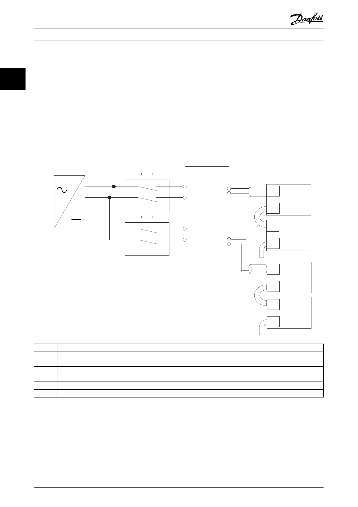
The temperature switch can be used as an overtemperature protection feature to prevent damage to the
2.11.1 Brake Resistor
22
When the servo drives are decelerating, the motors act like
a generator. This means that the energy coming back from
the servo drives is collected in the DC-link. The function of
the brake resistor is to provide a load on the DC-link
during braking, thereby ensuring that the brake power is
absorbed by the brake resistor. If no brake resistor is used
and the servo drives are decelerating, the DC-link voltage
will rise to a dangerous level. The SAB disconnects the ISD
lines when the DC-link voltage is too high. A DC-link
overvoltage will result in damage to the SAB and the servo
drives.
brake resistor caused by overtemperature.
The temperature switch can also be used to disable the
mains supply to the SAB by a contactor.
1. Connect the built-in thermal switch on the brake
resistor to the K1 input contactor.
2. Connect the start and stop push buttons in series
with the thermal switch.
3. Connect to a contactor in the mains supply on
the front of the SAB.
Thermal overheating in the brake resistor disables the
mains supply of the SAB.
2.11.1.1 Mechanical Installation
The brake resistors are cooled by natural convection.
The ventilation must be ecient enough to dispatch the
regenerative power in the brake resistor.
2.11.1.2 Electrical Installation
EMC precautions
The following EMC precautions are recommended to
achieve interference-free operation of eldbus cables, and
digital and analog inputs and outputs.
Observe any relevant national and local regulations, for
example regarding protective earth connection.
Keep the eldbus cables away from the brake resistor
cables to avoid coupling of high frequency noise from one
cable to the other. The minimum distance of 200 mm is
Illustration 2.14 Temperature Switch Disconnecting the Mains
from the SAB
sucient, however a greater distance between the cables
is recommended, especially where the cables run in
parallel over long distances. When crossing is unavoidable,
the eldbus cables must cross the brake cable at an angle
of 90°.
Cable connection
To comply with the EMC emission and immunity specication, the use of shielded/armored cables is mandatory.
Brake cable
Maximum length: 20 m shielded cable
Ensure that the connection cable to the brake resistor is
shielded. Use cable clamps to connect the shielding to the
conductive decoupling plate of the SAB, and to the brake
resistor metal cabinet.
Protective functions
The VLT® Brake Resistor MCE 101 is equipped with a
galvanic isolated temperature switch (PELV) that is closed
under normal operating conditions and opens if the brake
resistor overheats.
26 Danfoss A/S © 08/2017 All rights reserved. MG36C102
In addition, the brake power monitor function enables
readouts of the momentary power and the mean power
for a selected period. A brake power limit can be set and if
the brake power exceeds the set limit, the SAB issues a
warning or an error. When the SAB issues a warning, the
UDC output remains enabled. However, when an error is
issued, the UDC output to the servo drives is disconnected.
The brake is protected against short-circuiting of the brake
resistor, and the brake transistor is monitored to ensure
that short-circuiting of the transistor is detected.
2.11.1.3 Brake Resistor Calculation
To select the most suitable brake resistor for a given
application, the following information is required:
The number of servo drives in the application.
•
The inertia connected to the servo drives.
•
The braking/accelerating prole.
•

130BF780.10
AUX 1
Status
Hand
On
Reset
Auto
On
OK
Back
Cancel
Info
Quick
Menu
Main
Menu
Alarm
Log
AUX 2
SAFE 1
SAFE 2
SAB
400-480 V AC
Real-Time Ethernet
UDC
2
ISD 510
3
. . .
. . .
1
4
R
brake
P
peak brake
=
UDC
2
P
peak brake
UDC
2
R
brake min
778 V x 778 V
54.6 Ω
=== 11086 W
P
peak ISD
=
η
ISD x ωStart
x j x
Δt
Δω
P
peak ISD
=
η
ISD x nStart
x
x
j
x
60
2 x π
Δt
Δn
( )
System Overview Design Guide
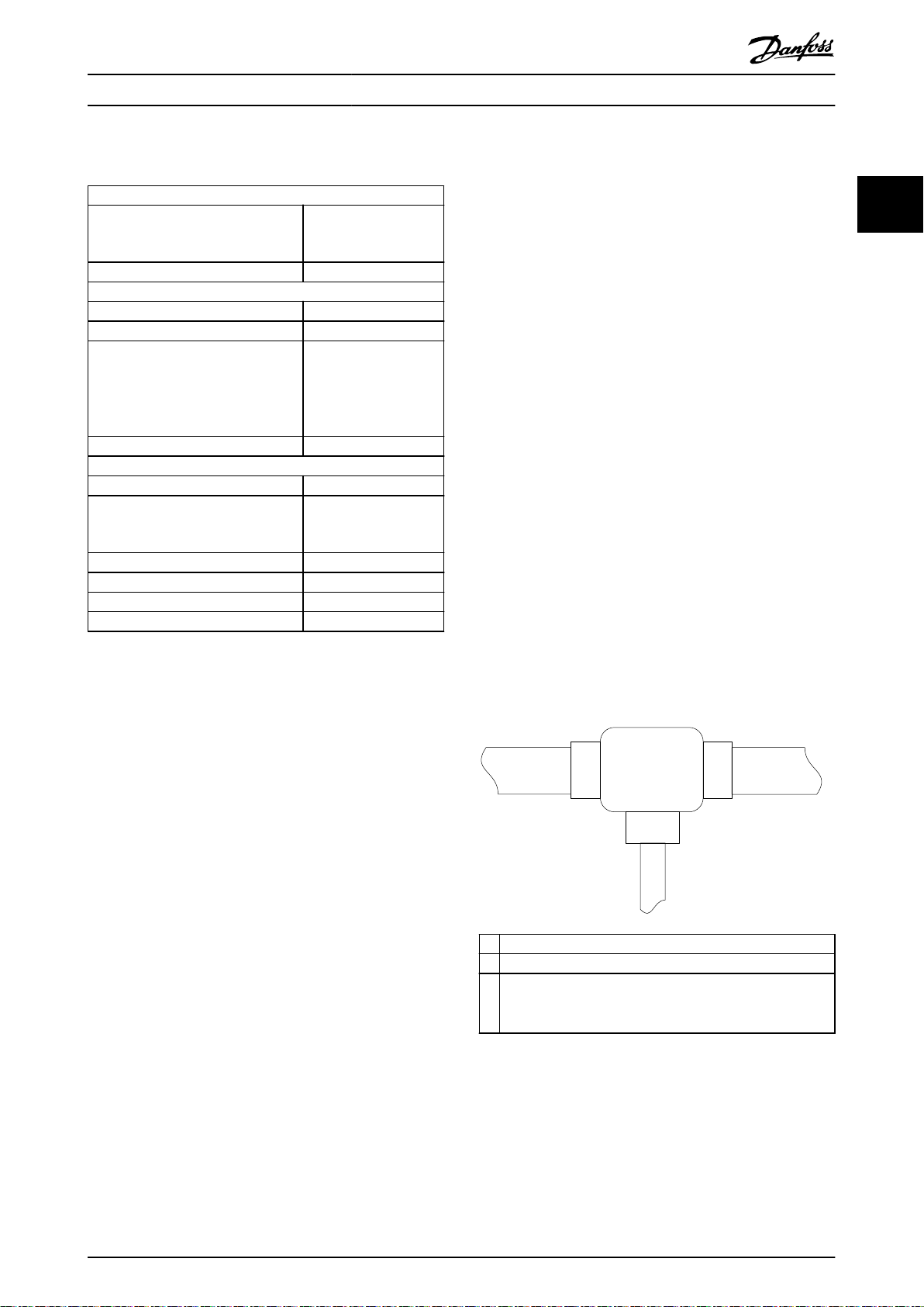
Brake set-up
Illustration 2.15 shows the brake set-up in the VLT
Integrated Servo Drive ISD 510 System.
®
Calculation of brake power
When calculating the brake power, ensure that the brake
resistor is scaled for the average power as well as for the
peak power.
The peak brake power depends on the number of
•
2 2
servo drives that are in acceleration mode and
deceleration mode. The torque used to accelerate
and decelerate is also important.
The average power is determined by the process
•
period time, for example the length of the
braking time in relation to the process period
time.
Calculation of brake resistor peak power
The brake active voltage for the SAB is 778 V. When using
the minimal brake resistance of 54.6 Ω, a current of
14.25 A will ow at 778 V.
The brake resistor peak power is then calculated as follows:
1 I
brake
2 P
Line
3 P
ISD
4 Brake resistor R
: Absorbs brake power P
brake
Illustration 2.15 Brake Set-up
brake
.
If the application does not require braking with the
maximum current, a higher brake resistance can be
selected. A higher brake resistance results in a lower brake
peak power.
When the servo drives are accelerating, P
When the servo drives are decelerating, P
If the sum of all P
connected to the SAB results in a
ISD
is positive.
ISD n
is negative.
ISD n
negative value, the energy must be absorbed in the brake
resistor.
Brake resistance
To prevent the SAB from cutting out for protection when
the servo drives are braking, select brake resistor values on
the basis of the peak braking power.
If the sum of all P
is positive, energy from the mains is
ISD n
converted into rotation energy and the brake resistor does
not need to absorb energy.
To calculate the peak brake power, select the moment
where the most servo drives are decelerating and the
fewest servo drives are accelerating.
The peak power of a decelerating servo drive can be
The SAB starts braking when the UDC voltage exceeds
calculated as:
778 V.
The brake resistor can range from 54.6–200 Ω. Brake
resistors within this range are detected by the congurable
brake check. The brake check is executed each time before
the SAB enters the state Operation enabled and when
mains is powered up. The brake check activates the brake
and checks if the DC-link voltage drops.
The minimum brake resistance is 54.6 Ω. When higher
brake resistor resistance is selected, the maximum braking
torque cannot be reached, and there is a risk that the SAB
will cut out due to DC-link overvoltage protection.
j: Shaft inertia
n
: Eciency of the servo drive (typically 0.88)
ISD
MG36C102 Danfoss A/S © 08/2017 All rights reserved. 27

ω Start
ω Stop
∆t
∆ω/∆t
175ZA863.11
P
peak ISD line 1
=
P
Peak ISD 1.1
+ P
Peak ISD 1.2 + PPeak ISD 1.n + . . .
P
peak brake
=
P
Peak ISD line 1
+ P
Peak ISD line 2
P
[W]
P
peak
P
avg
T
p
T
b
t [s]
175ZA094.13
P
ave
=
P
peak x
T
p
T
b
Duty cycle [%]
=
T
p x 100
T
b
System Overview
VLT® Integrated Servo Drive ISD® 510 System
The duty cycle is calculated as follows:
22
Danfoss oers brake resistors with a duty cycle of
maximum 10% and 40%. If a 10% duty cycle is applied, the
brake resistors are able to absorb P
period time. The remaining 90% of the period is used on
deecting excess heat.
2.11.2 External Encoder and Sensors
Illustration 2.16 Decelerating Servo Drive
2.11.2.1 External Encoder
for 10% of the
peak
The peak power connected to line 1 can be calculated as:
The calculation for line 2 can be done in the same way.
The maximum peak brake power is the sum of the peak
brake power on both lines when the result is a negative
value.
With P
, the optimal resistance value can be
peak brake
calculated using the formula for brake resistance.
Calculation of brake resistor average power
The average power is determined by the length of the
braking time in relation to the process period.
An external encoder can be connected to the X4
connector on the advanced servo drive or the encoder
connector on the SAB. The encoder value can be used as
guide value provider.
Further information on external encoders and sensors can
be found in the VLT
®
Integrated Servo Drive ISD® 510
Operating Instructions.
2.11.2.2 Sensor
The M12 I/O and/or encoder connector (X4) is available of
the advanced servo drive. See chapter 6.1.2.1 Connectors on
the Servo Drives for pin assignment.
T
Process period time in s.
p
T
Braking time in s.
b
Illustration 2.17 Relation between Average Power and Peak
Power
The average power is calculated as follows:
28 Danfoss A/S © 08/2017 All rights reserved. MG36C102

Relay1
Relay2
03
02
240 V AC, 2 A
240 V AC, 2 A
400 V AC, 2 A
01
06
05
04
130BA047.11
DRIVE STAT X1
X2
X3
NET STAT
LINK/ACT
DRIVE STAT X1
X2NET STAT
LINK/ACT
Advanced Standard
130BE677.10
System Overview Design Guide
2.11.3 Relays
Relays are used for customer-dened reactions. For
example, the relay can be triggered if the SAB issues a
warning.
- Use the LCP to read out the error or
warning that occurred last on either the
servo drive or the SAB.
- Use the DDS Toolbox to read out the
error or warning that occurred last on
either the servo drive or the SAB, or to
read out a history of errors that
occurred.
-
Use the Danfoss VLT® Servo Motion
library on the PLC to read out the error
or warning that occurred last.
®
Refer to the VLT
Integrated Servo Drive ISD 510 System
Programming Guide for details on how to use the
mentioned functions and the list of fault codes.
2 2
Illustration 2.18 Relay Outputs 1 and 2
See chapter 6.2.3.4 Relay Connectors for further information.
Faults, Warnings, and Alarm Functions
2.12
2.12.1 Overview
For diagnostic purposes, there are several possibilities to
obtain information:
Current status
•
- The LEDs on the ISD 510 servo drive
(see Illustration 2.19) show the current
status of the servo drive.
- The LEDs on the SAB (see
Illustration 2.20) show the current status
of the SAB.
Readout of errors/warnings
•
2.12.2
Operating LEDs on the VLT
®
Integrated Servo Drive ISD 510
Illustration 2.19
drive.
Illustration 2.19 Operating LEDs on the Servo Drive
LED Color Flash status Description
DRIVE
STAT
NET
STAT
shows the operating LEDs on the servo
Green On Servo drive is in state
Operation enabled.
Flashing Auxiliary voltage is
applied.
Red On Servo drive is in Fault
or Fault reaction active
state.
Flashing DC-link voltage is not
applied.
Green/
Fieldbus dependent Network status of the
red
device (see
corresponding eldbus
standard).
MG36C102 Danfoss A/S © 08/2017 All rights reserved. 29

130BE733.11
Aux 1
Aux 2
Safe 1
Safe 2
SAB STAT
NET STAT
LINK
ACT
X1
X4
X3
X2
System Overview
VLT® Integrated Servo Drive ISD® 510 System
LED Color Flash status Description
Link/A
Green – Link/activity status of
CT X1
22
On Ethernet link
Hybrid In (X1)
established.
Flashing Ethernet link
established and active.
O No link.
Link/A
Green – Link/activity status of
CT X2
Hybrid Out (X2)
On Ethernet link
established.
Flashing Ethernet link
established and active.
O No link.
Link/A
Green – Link/activity status of
CT
X3
1)
On Ethernet link
the Ethernet port (X3).
established.
Flashing Ethernet link
established and active.
O No link.
Table 2.12 Legend to Illustration 2.19
1) Advanced version only
2.12.3
Operating LEDs on the VLT® Servo
Access Box
LED Color Flash status Description
Aux 1 Green – State of the auxiliary
voltage on line 1.
On State machine is in
state Standby, Power
up, or Operation
enabled. Auxiliary
voltage is applied to
the output connectors
on line 1.
O State machine is in
state U
disabled or
AUX
Fault. Auxiliary voltage
is not applied to line 1.
Aux 2 Green – State of the auxiliary
voltage on line 2.
On State machine is in
state Standby, Power
up, or Operation
enabled. Auxiliary
voltage is applied to
the output connectors
on line 2.
O State machine is in
state U
disabled or
AUX
Fault. Auxiliary voltage
is not applied to line 2.
Safe 1 Green On 24 V for STO is present
on line 1.
O 24 V for STO is not
present on line 1.
Safe 2 Green On 24 V for STO is present
on line 2.
O 24 V for STO is not
present on line 2.
SAB
Green On SAB is in state
STAT
Operation enabled.
Flashing Auxiliary voltage is
applied at the input.
O No auxiliary voltage is
applied at the input.
Red On The SAB is in state
Fault.
Flashing Mains is not applied at
the input.
device (see
corresponding eldbus
standard).
In.
Illustration 2.20 Operating LEDs on the SAB
NET
Green/
Fieldbus dependent. Network status of the
STAT
red
Link/A
Green – Link/activity status of
CT X1
On Ethernet link
established.
Flashing Ethernet link
established and active.
O No link.
30 Danfoss A/S © 08/2017 All rights reserved. MG36C102

System Overview Design Guide
LED Color Flash status Description
Link/A
Green – Link/activity status of
CT X2
On Ethernet link
Flashing Ethernet link
O No link.
Link/A
Green – Link/activity status of
CT X3
On Ethernet link
Flashing Ethernet link
O No link.
Link/A
Green – Link/activity status of
CT X4
On Ethernet link
Flashing Ethernet link
O No link.
Table 2.13 Legend to Illustration 2.20
User Interfaces
2.13
Out.
established.
established and active.
line 1.
established.
established and active.
line 2.
established.
established and active.
2.13.1 Overview
The LCP is the graphical user interface on the SAB for
diagnostic and operating purposes. It is included as
standard with the SAB but can also be connected to the
advanced version servo drives using an optional cable
(M8 to LCP SUB-D extension cable).
The LCP display provides the operator with a quick view of
the state of the servo drive or SAB, depending on which
device it is connected to. The display shows parameters
and alarms/errors and can be used for commissioning and
troubleshooting. It can also be used to perform simple
functions, for example activating and deactivating the
output lines on the SAB.
2.13.2 DDS Toolbox Software
The DDS Toolbox is a standalone PC software designed by
Danfoss. It is used for parameterization and diagnostics of
the servo drives and the SAB. See chapter 2.8.2 PC-Software
for further details.
2.13.3 Overview
The libraries provided for the VLT® Integrated Servo Drive
ISD 510 System can be used in TwinCAT® V2 and in the
Automation Studio™ (Version 3.0.90 and 4.x, supported
platform SG4) environment to easily integrate the
functionality without the need of special motion run-time
on the controller. The provided function blocks conform to
the PLCopen® standard. Knowledge of the underlying
eldbus communication and/or the CANopen® CiA DS 402
prole is not necessary.
The library contains:
Function blocks for controlling and monitoring
•
the servo drive and the SAB.
Function blocks for all available motion
•
commands of the servo drive.
Function blocks and structures for creating Basic
•
CAM
proles.
Function blocks and structures for creating
•
Labeling CAM proles.
2.13.4
The VLT® Integrated Servo Drive ISD 510 can be operated
with the built-in NC functionality of TwinCAT®. This means
that the trajectory calculations are all done within the PLC.
The servo drive can be used with cyclic synchronous
position mode or cyclic synchronous velocity mode to
follow the setpoints given by the controller. The features
are provided by the TwinCAT® library. To use this
functionality, the controller must have an NC-PTP-Runtime
system installed.
TwinCAT® NC Axis
2 2
The LCP can be mounted on the front of the control
cabinet and then connected to the SAB via SUB-D cables
(available as an accessory).
NOTICE
Do not permanently connect the LCP to the servo drive.
Doing so will reduce the IP-rating.
MG36C102 Danfoss A/S © 08/2017 All rights reserved. 31
For details on how to congure the servo drive to use this
functionality, refer to the VLT® Integrated Servo Drive ISD
510 System Programming Guide.
®
NOTICE
A servo drive can either be controlled by the Danfoss
VLT® Servo Motion library, or operated as a TwinCAT® NC
axis. However, it is possible to mix both types of
operation within 1 application.

Application Examples
3 Application Examples
3.1 Intended Applications
VLT® Integrated Servo Drive ISD® 510 System
33
There are numerous possible applications for the VLT
Integrated Servo Drive ISD® 510 system as per the
following examples.
Beverage machines:
Labelling
•
Capping
•
Filling
•
PET blow-moulding
•
Digital bottle printing
•
Food and beverage packaging machines:
Flow wrapping
•
Bag maker
•
Tray sealing
•
Shrink wrapping
•
Industrial and pharmaceutical packaging machines:
Palletization
•
Top loader
•
Cartoning
•
Tube lling
•
Blister machine
•
Liquid lling
•
Solid dosing
•
®
32 Danfoss A/S © 08/2017 All rights reserved. MG36C102

12°
1.2
Ø960
97
130BF956.10
System Integration Design Guide
4 System Integration
4.1
Operating Environment: VLT
®
Integrated Servo Drive ISD 510
4.1.1 Humidity
Although the VLT® Integrated Servo Drive ISD 510 can
operate properly at high humidity, avoid condensation.
There is a specic risk of condensation when the servo
drive is colder than moist ambient air. Moisture in the air
can also condense on the electronic components and
cause short circuits. Condensation occurs in units without
power. Avoid installation in areas subject to frost. Alternatively, operating the servo drive in standby mode (with the
servo drives connected to the auxiliary power supply via
the SAB) reduces the risk of condensation. Ensure that the
power dissipation is sucient to keep the servo drive
circuitry free of moisture.
4.1.2 Ambient Temperature
Minimum and maximum ambient temperature limits are
specied for the VLT® Integrated Servo Drive ISD 510 (see
chapter 6.1.4 General Specications and Environmental
Conditions). Avoiding extreme ambient temperatures
prolongs the life of the equipment and maximizes the
overall system reliability. Follow the recommendations
listed for maximum performance and equipment longevity.
4.1.3 Cooling
The servo drives are self-cooling. Cooling (heat dispersal) is
primarily via the ange, with a small amount dispersed by
the housing. The following recommendations are necessary
for eective cooling of the units.
Maximum air temperature to enter enclosure
•
must never exceed 55 °C (131 °F).
Day/night average temperature must not exceed
•
35 °C (95 °F).
Mount the unit to allow for free cooling airow.
•
Provide minimum front and rear clearance
•
requirements for cooling airow.
It is possible to install 2 or more servo drives next to each
other, however the surfaces of the servo drives must not
be in contact with each other. Ensure that there is a
minimum gap of 1.2 mm between the servo drives to
provide adequate ventilation of the servo drives and to
allow sucient heat transfer to take place in the
surrounding areas.
4 4
Although the servo drive can operate at temper-
•
atures as low as 0 °C, proper operation at rated
load is only guaranteed at ≥5 °C.
Do not exceed the maximum temperature limit.
•
The lifetime of electronic components decreases
•
by 50% for every 10 °C operated above the
design temperature.
Devices with IP54, IP65, or IP67 protection ratings
•
must also adhere to the
temperature ranges.
Additional air conditioning of the cabinet or
•
installation site may be required.
specied ambient
Illustration 4.1 Example of Servo Drive Installation on the
Same Flange
4.1.4 Motor-generated Overvoltage
The DC voltage in the intermediate circuit (DC bus)
increases when the servo drive acts as a generator. This
can occur in 2 ways:
The load drives the servo drive when it is
•
operated at a constant speed. This is referred to
as an overhauling load.
During deceleration, if the inertia of the servo
•
drives is high and the deceleration of the servo
drives is set to a high value.
MG36C102 Danfoss A/S © 08/2017 All rights reserved. 33

System Integration
VLT® Integrated Servo Drive ISD® 510 System
The SAB cannot regenerate energy back to the grid. It is
possible to connect and congure a brake resistor to the
SAB that can consume some power if the DC-link voltage
becomes too high (see chapter 2.11.1 Brake Resistor). If this
is unsuccessful, or if the load drives the servo drive, the
SAB shuts down and shows a fault when a critical DC bus
voltage level is reached.
The servo drive cannot regenerate energy back to the
44
input. Therefore, it limits the energy accepted from the
motor. If this is unsuccessful, or if the load drives the
motor, the servo drive shuts down and displays a fault
when a critical DC bus voltage level is reached.
4.1.5 Acoustic Noise
Acoustic noise from the servo drive comes from the
following sources:
Shaft seal
•
Ball bearings
•
Speed
•
Brake
•
4.1.6 Vibration and Shock
The VLT® Integrated Servo Drive ISD 510 is tested
according to a procedure based on IEC 60068-2-64.
The servo drive is intended for use on rotary parts/
machines.
Operating Environment: SAB
4.2
4.2.1 Humidity
Follow the recommendations listed for maximum
performance and equipment longevity.
Although the SAB can operate at temperatures
•
down to 0 °C, proper operation at rated load is
only guaranteed at ≥5 °C.
Do not exceed the maximum temperature limit.
•
The lifetime of electronic components decreases
•
by 50% for every 10 °C operated above the
design temperature.
Additional air conditioning of the cabinet or
•
installation site may be required.
4.2.3 Cooling
The SAB dissipates power in the form of heat. Cooling
(heat dispersal) is primarily via the integrated fans. The
following recommendations are necessary for eective
cooling of the units.
Maximum air temperature to enter enclosure
•
must never exceed 50 °C (122 °F).
Day/night average temperature must not exceed
•
45 °C (113 °F).
Mount the unit to allow for free cooling airow
•
through the cooling ns. See
chapter 6.2.2 Clearance for correct mounting
clearances.
Provide minimum front and rear clearance
•
requirements for cooling airow. See the VLT
Integrated Servo Drive ISD 510 System Operating
Instructions for the installation requirements.
®
4.2.3.1 Cooling Fans
Although the SAB can operate properly at high humidity,
avoid condensation. There is a specic risk of condensation
when the SAB is colder than moist ambient air. Moisture in
the air can also condense on the electronic components
and cause short circuits. Condensation occurs in units
without power. It is recommended to install a cabinet
heater when condensation is possible due to ambient
conditions. Avoid installation in areas subject to frost.
Alternatively, operating the SAB in standby mode (with the
unit connected to the mains) reduces the risk of condensation. Ensure that the power dissipation is sucient to
keep the SAB circuitry free of moisture.
The SAB has built-in fans to ensure optimum cooling. The
main fan forces the airow along the cooling ns on the
heat sink, ensuring cooling of the internal air. The SAB has
a small secondary fan on the power control board,
ensuring that the internal air is circulated to avoid hot
spots. The main fan is controlled by the internal
temperature in the SAB and the speed gradually increases
along with temperature. This reduces noise and energy
consumption when the need is low, and ensures maximum
cooling when needed.
In case of overtemperature inside the SAB, an alarm or
warning is issued and a coast and trip lock occurs.
4.2.2 Ambient Temperature
Minimum and maximum ambient temperature limits are
specied for the SAB (see chapter 6.2.5 General Speci-
cations and Environmental Considerations). Avoiding
extreme ambient temperatures prolongs the life of the
equipment and maximizes the overall system reliability.
34 Danfoss A/S © 08/2017 All rights reserved. MG36C102

V
=
T
i
– T
A
f x Q
System Integration Design Guide
4.2.3.2 Calculation of Airow Required for
Cooling the SAB
The airow required to cool the SAB (or multiple SABs in 1
cabinet) can be calculated as follows:
1. Determine the power loss at maximum output for
all SABs.
2. Add the power loss values of all SABs that can
operate at same time. The resulting sum is the
heat Q to be transferred. Multiply the result with
the factor f, read from Table 4.2.
For example, f = 3.1 m3 x K/Wh at sea level.
3. Determine the highest temperature of the air
entering the enclosure. Subtract this temperature
from the required temperature inside the
enclosure, for example 45 °C (113 °F).
4. Divide the total from step 2 by the total from
step 3.
The calculation is expressed by the following formula:
V
f
Q Heat to be transferred in W
T
i
T
A
Airow in m3/h
Factor in m3 x K/Wh (calculated as: cp x ρ (specic
heat of air x density of air))
Temperature inside the enclosure in °C
Ambient temperature in °C
Example
How to calculate the airow required to cool 2 SABs (with
heat losses of 295 W and 1430 W) running simultaneously,
mounted in an enclosure with an ambient temperature
peak of 37 °C, and an installation altitude of 500 m:
1. The sum of the heat losses of both frequency
converters (295 + 150 W) = 445 W.
2.
Multiply 445 W by 3.3 m3 x K/Wh = 1468.5 m3 x
K/h.
3.
Subtract 37 °C from 45 °C = 8 °C (=8 K).
4.
Divide 1468.5 m3 x K/h by 8 K = 183.56 m3/h.
airow is required in CFM (cubic feet per minute),
If the
use the conversion 1 m3/h = 0.589 CFM. For this example,
183.56 m3/h = 108.1 CFM.
4.2.4 Acoustic Noise
Acoustic noise from the SAB comes from 3 sources:
DC-link (intermediate circuit) coils
•
RFI lter choke
•
Internal fans
•
The acoustic noise ratings shown in Table 4.3 were
measured 1 m from the unit.
50% fan speed [dBA] Full fan speed [dBA]
SAB 51 60
Table 4.3 Acoustic Noise Ratings
4 4
Table 4.1 Formula Abbreviations
NOTICE
Specic heat of air (cp) and density of air (ρ) are not
constants, but depend on temperature, humidity, and
atmospheric pressure. Therefore, they depend on the
altitude above sea level.
Table 4.2 shows typical values of the factor f, calculated
for dierent altitudes.
Altitude
[m]
0 0.9480 1.225 3.1
500 0.9348 1.167 3.3
1000 0.9250 1.112 3.5
1500 0.8954 1.058 3.8
2000 0.8728 1.006 4.1
2500 0.8551 0.9568 4.4
3000 0.8302 0.9091 4.8
3500 0.8065 0.8633 5.2
Table 4.2 Factor f, Calculated for Various Altitudes
Specic heat of air (cp)
[kJ/kgK]
Density of air (p)
[kg/m3]
Factor (f)
[m3K/Wh]
4.2.5 Vibration and Shock
The SAB is tested according to a procedure based on the
IEC 60068-2-6. The SAB complies with requirements that
correspond to these conditions when the unit is wall or
oor-mounted, as well as when mounted within panels, or
bolted to walls or oors.
Operating Environment: General
4.3
4.3.1 Aggressive Atmospheres
4.3.1.1 Gases
Aggressive gases, such as hydrogen sulphide, chlorine, or
ammonia can damage SAB electrical and mechanical
components. Contamination of the cooling air can also
cause the gradual decomposition of PCB tracks and door
seals. Aggressive contaminants are often present in sewage
treatment plants or swimming pools. A clear sign of an
aggressive atmosphere is corroded copper.
In aggressive atmospheres, restricted IP enclosures of
cabinet are recommended.
MG36C102 Danfoss A/S © 08/2017 All rights reserved. 35

System Integration
VLT® Integrated Servo Drive ISD® 510 System
Class
Gas type Unit
Sea salt n/a 0.1 0.3 1.0 5.0 10.0
Sulphur
oxides
Chlorine mg/m³0.01 0.1 0.03 0.3 1.0
3C1 3C2 (SAB) 3C3 (ISD)
Average
value
mg/m³0.01 0.1 0.5 3.0 10.0
Maximum
1)
value
Average
value
Maximum
value
1)
44
Hydrogen
chloride
Hydrogen
uoride
Ammonia mg/m³0.3 1.0 3.0 10.0 35.0
mg/m³0.01 0.1 0.5 1.0 5.0
mg/m³0.003 0.01 0.03 0.1 3.0
Servo Access Box:
Installation of the SAB in environments with high dust
exposure is often unavoidable. Dust aects wall- or framemounted units and also cabinet-mounted devices with
IP20 protection ratings. Consider the 2 aspects described in
this section when the SAB is installed in such
environments.
Reduced cooling
Dust forms deposits on the surface of the device and
inside on circuit boards and the electronic components.
These deposits act as insulation layers and hamper heat
transfer to the ambient air, reducing the cooling capacity.
The components become warmer. This causes accelerated
aging of the electronic components, and the service life of
the SAB decreases. Dust deposits on the heat sink at the
back of the SAB also decrease the service life.
Ozone mg/m³0.01 0.05 0.1 0.1 0.3
Cooling fans
The airow for cooling the SAB is produced by cooling fans
Nitrogen mg/m³0.1 0.5 1.0 3.0 9.0
on the top and bottom of the SAB. The fan rotors have
small bearings into which dust can penetrate and act as an
Table 4.4 Conformal Coating Values
1) Maximum values are transient peak values not to exceed 30
minutes per day.
abrasive. This leads to bearing damage and fan failure.
Periodic maintenance:
Under the conditions described above, it is recommended
to clean the SAB during periodic maintenance. Remove
4.3.1.2 Exposure to Dust
dust from the heat sink and fans.
Servo drive:
Installation of the servo drives in environments with high
dust exposure is often unavoidable. Dust aects the servo
drives with IP54, IP65, and IP67 protection ratings. Consider
the 2 aspects described in this section when servo drives
are installed in such environments.
Reduced cooling
Dust forms deposits on the surface of the device and
inside on circuit boards and the electronic components.
These deposits act as insulation layers and hamper heat
transfer to the ambient air. This reduces the cooling
capacity, resulting in the components becoming warmer.
This causes accelerated aging of the electronic
components, and the service life of the servo drive
decreases.
Shaft seal
Dust can form deposits on the shaft and can lead to
abrasion on the shaft seal. This can lead to a reduced
lifetime of the shaft seal.
Periodic maintenance
Under the conditions described above, it is recommended
to clean the servo drive during periodic maintenance.
Remove dust from the housing and the shaft.
4.3.2 Electromagnetic Compatibility
4.3.2.1 Emission Requirements
The EMC product standard for frequency converters
denes 4 categories (C1, C2, C3, and C4) with specied
requirements for emission and immunity. Table 4.5 states
the denition of the 4 categories and the equivalent classication from EN 55011.
The VLT® Integrated Servo Drive ISD 510 System complies
with the emission limits Class A Group 1 according to EN
55011 and Category C2 according to EN 61800-3.
36 Danfoss A/S © 08/2017 All rights reserved. MG36C102

System Integration Design Guide
Categ
Denition Equivalent emission class
ory
C1 Frequency converters
installed in the rst
environment (home and
oce) with a supply voltage
less than 1000 V.
C2 Frequency converters
installed in the rst
environment (home and
oce) with a supply voltage
less than 1000 V, which are
not plug-in or movable and
are intended to be installed
and commissioned by a
professional.
C3 Frequency converters
installed in the second
environment (industrial) with
a supply voltage lower than
1000 V.
C4 Frequency converters
installed in the second
environment with a supply
voltage equal to or above
1000 V or rated current
equal to or above 400 A or
intended for use in complex
systems.
in EN 55011
Class B
Class A Group 1
Class A Group 2
No limit line. Make an
EMC plan.
EN 61000-4-4 (IEC 61000-4-4): Burst transients:
•
Simulation of interference brought about by
switching a contactor, relay, or similar devices.
EN 61000-4-5 (IEC 61000-4-5): Surge transients:
•
Simulation of transients brought about for
example by lightning that strikes near installations.
EN 61000-4-6 (IEC 61000-4-6): RF Common mode:
•
Simulation of the eect from radio-transmission
equipment joined by connection cables.
4 4
Table 4.5 Correlation between IEC 61800-3 and EN 55011
4.3.2.2 Immunity Requirements
The immunity requirements for the servo drives and SAB
depend on the environment where they are installed. The
requirements for the industrial environment are higher
than the requirements for the home and oce
environment. All servo drives and the SABs comply with
the requirements for the industrial environment and
consequently also comply with the lower requirements for
home and oce environment with a large safety margin.
The VLT® Integrated Servo Drive ISD 510 System complies
with the immunity requirements for 2nd environment
according to EN 61800-3.
To document immunity against electrical interference, the
following immunity tests have been made in accordance
with following basic standards:
EN 61000-4-2 (IEC 61000-4-2): Electrostatic
•
discharges (ESD): Simulation of electrostatic
discharges from human beings.
EN 61000-4-3 (IEC 61000-4-3): Incoming electro-
•
magnetic eld radiation, amplitude modulated
simulation of the eects of radar and radio
communication equipment as well as mobile
communications equipment.
MG36C102 Danfoss A/S © 08/2017 All rights reserved. 37

130BF957.10
L1
L2
L3
PE
1
2
3
8
4
5
6
7
11
9
10
Aux 1
Aux 2
Safe 1
Safe 2
System Integration
VLT® Integrated Servo Drive ISD® 510 System
Radiated
electro-
magnetic
eld
IEC
Basic
standard
Burst
IEC
61000-4-4
Surge
IEC
61000-4-5
ESD
IEC
61000-4-2
61000-4-3
Acceptance
Criterion
Line 2 kV/
44
Brake 2 kV/
B B B A A
5 kHz
5 kHz
1 kV DM
2 kV CM
– – – 10 V
– – 10 V
Relay wires
2 kV/
5 kHz
2 kV
1)
– – 10 V
LCP cable – – – – 10 V
SAB
Encoder
cable
Ethernet
cable
U
AUX
supply
cable
U
safe
supply
cable
Feed-in
cable
Loop cable 2 kV/
M8 LCP
cable
rd
M8 3
Ethernet
cable
M12
Sensor
cable
Enclosure
2 kV/
5 kHz
2 kV/
5 kHz
2 kV/
5 kHz
2 kV/
5 kHz
2 kV/
5 kHz
5 kHz
– – – 10 V
1 kV
1)
– – 10 V
– – – 10 V
1 kV
1 kV
1 kV
1)
1)
1)
– – 10 V
– – 10 V
– – 10 V
– – – – 10 V
2 kV/
5 kHz
2 kV/
5 kHz
– – – 10 V
– – – 10 V
80 MHz –
RF
common
mode
voltage
IEC
61000-4-6
RMS
RMS
RMS
RMS
RMS
RMS
RMS
RMS
RMS
RMS
RMS
RMS
RMS
4.3.2.3 Grounding for Electrical Safety
Ground the servo drive with the PE wire of the
•
feed-in cable.
Ensure that the machine frame has a proper
•
electrical connection to the ange of the servo
drive because this is the main PE connection. Use
the front side ange surface. Ensure PE
connection on that part of the machine.
Ensure that the ground connections are tight and
•
free of oxidation for the lifetime of the machine.
Use a dedicated ground wire for input power and
•
control wiring.
Do not ground 1 SAB to another in daisy-chain
•
format.
Keep the ground wire connections as short as
•
possible.
Follow the wiring requirements in this manual.
•
Ensure a minimum ground wire cross-section of
•
10 mm2 on the SAB, or 2 separate ground wires,
both complying with the dimensioning rules.
See EN/IEC 61800-5-1 for further information on
•
grounding.
1 GHz:
10 V/m
1.4 GHz –
2.7 GHz:
3 V/m
–
– –
4 kV CD
8 kV AD
2.0 GHz –
2.7 GHz:
1 V/m
Table 4.6 EMC Immunity Form
1) Injection on cable shield.
1 Servo Access Box
(SAB)
7
Equalizing minimum 16 mm
(AWG 5)
2 Control cabinet 8 Feed-in cable
3 Servo drive 9 Grounding rail (PE)
4 Machine frame 10 Grounding of feed-in cable
5 Flange 11 Mains, 3-phase, and reinforced PE
6 Shaft – –
Illustration 4.2 Recommended Installation for Electrical Safety
2
38 Danfoss A/S © 08/2017 All rights reserved. MG36C102

System Integration Design Guide
4.3.2.4 EMC Grounding
Proper EMC grounding practice:
Respect safety grounding.
•
The best EMC performance is achieved when the
•
ground connection is kept as short as possible.
Wires with a large cross-section have lower
•
impedance and better EMC grounding.
In cases where more devices with metal cabinets
•
are used, mount them on a common metal
mounting plate to improve EMC performance.
NOTICE
If necessary, use washers for fastening bolts, for example,
in case of painted parts.
Grounding for EMC-compliant installation
Establish electrical contact between the cable
•
shield and the SAB enclosure by using metal
cable glands, or by using the clamps provided on
the SAB.
Use high-strand wire to reduce electrical
•
interference.
Do not use pigtails.
•
Ensure a minimum distance of 200 mm between
•
signal and power cables.
Only cross cables at 90°.
•
NOTICE
POTENTIAL EQUALIZATION
There is a risk of electrical interference when the ground
potential between the servo system and the machine is
dierent. Install equalizing cables between the system
components. The recommended cable cross-section is
16 mm2.
NOTICE
EMC INTERFERENCE
Use shielded cables for control wiring and separate
cables for power and control wiring. Failure to isolate
power and control wiring can result in unintended
behavior or reduced performance. Ensure a minimum
clearance of 200 mm between signal and power cables.
4.3.2.5 Motor Bearing Currents
To minimize bearing and shaft currents, ground the
following to the driven machine:
SAB
•
Servo drive
•
Driven machine
•
Standard mitigation strategies:
1. Apply rigorous installation procedures:
1a Ensure that the motor and motor load
are aligned.
1b Strictly follow the EMC Installation
guideline.
1c Reinforce the PE so the high frequency
impedance is lower in the PE than the
input power leads.
1d Provide a good high frequency
connection between the system
components, for instance, by using
shielded cable.
1e Make sure that the impedance from the
VLT® Integrated Servo Drive ISD 510
System to building ground is lower that
the grounding impedance of the
machine.
1f Make a direct ground connection
between the motor and load motor.
2. Install a shaft grounding system or use an
isolating coupling.
3. Apply conductive lubrication.
4. Use minimum speed settings if possible.
5. Try to ensure that the line voltage is balanced to
ground.
4.3.2.6 Earth Leakage Current
Follow national and local codes regarding protective
earthing of equipment where leakage currents are
>3.5 mA. High frequency switching at high power
generates a leakage current in the ground connection.
The earth leakage current is made up of several contributions and depends on various system congurations,
including:
RFI ltering.
•
Cable length.
•
Cable shielding.
•
Frequency converter power.
•
Compliance with EN/IEC61800-5-1 (power drive system
product standard) requires special care if the leakage
current is >3.5 mA. Reinforce grounding with the following
protective earth connection requirements:
Ground wire (terminal 95) of at least 10 mm
•
cross-section.
2 separate ground wires, both complying with
•
the dimensioning rules.
See EN/IEC 61800-5-1 and EN 50178 for further
information.
2
4 4
MG36C102 Danfoss A/S © 08/2017 All rights reserved. 39

130BB958.12
f
sw
Cable
150 Hz
3rd harmonics
50 Hz
Mains
RCD with low f
cut-
RCD with high f
cut-
Leakage current
Frequency
130BB957.11
Leakage current [mA]
100 Hz
2 kHz
100 kHz
System Integration
VLT® Integrated Servo Drive ISD® 510 System
Using RCDs
4.3.2.7 Touch Current
Where residual current devices (RCDs), also known as earth
leakage circuit breakers (ELCBs), are used, comply with the
following:
Only use type B RCDs, as they are capable of
•
detecting AC and DC currents.
Use RCDs with a delay to prevent faults due to
•
transient ground currents.
Dimension RCDs according to the system congu-
44
•
ration and environmental considerations.
The leakage current includes several frequencies
originating from both the mains frequency and the
switching frequency. Whether the switching frequency is
detected depends on the type of RCD used.
The purpose of the touch current is to test if the leakage
current in the protective earth (PE) of the power drive
system is less than 3.5 mA AC or 10 mA DC.
If the leakage current is below or equal to 3.5 mA AC or
10 mA DC, no special measures relating to the PE
connection are required.
The leakage current of the VLT® Integrated Servo Drive
ISD 510 System is greater than 3.5 mA AC or 10 mA DC,
therefore a xed connection is required and 1 or more of
the following conditions must be satised when installing
the DUT:
1. A cross-section of the protective earthing
conductor of at least 10 mm² Cu or 16 mm² Al.
2. Automatic disconnection of the supply in case of
discontinuity of the protective earthing
conductor.
3. Provision of an additional terminal for a
protective earthing conductor of the same crosssectional area as the original protective earthing
conductor.
The amount of leakage current detected by the RCD
depends on the cut-o frequency of the RCD.
Illustration 4.3 Main Contributions to Leakage Current
WARNING
LEAKAGE/GROUNDING CURRENT HAZARD
Leakage/grounding currents are >3.5 mA. Failure to
ground the SAB and the servo drives properly could
result in death or serious injury.
Ensure the correct grounding of the SAB and
•
servo drives by a certied electrical installer in
accordance with applicable national and local
electrical standards and directives, and the
instructions contained in this manual.
Illustration 4.4 Inuence of RCD Cut-o Frequency on Leakage
Current
40 Danfoss A/S © 08/2017 All rights reserved. MG36C102

130BE724.10
IM B5 IM V1 IM V3
System Integration Design Guide
4.3.3 IP Ratings
4.3.3.1 Denitions
First digit Against penetration by
solid foreign objects
0 (not protected) (not protected)
1 ≥50 mm diameter Back of hand
2 12.5 mm diameter Finger
3 2.5 mm diameter Tool
4 ≥1.0 mm diameter Wire
5 Dust protected Wire
6 Dust-tight Wire
Second
digit
First letter – Additional information
Additional
letter
Table 4.7 IEC 60529 Denitions for IP Ratings
Against water
penetration with
harmful eect
0 (not protected) –
1 Drops falling vertically –
2 Drops at 15° angle –
3 Spraying water –
4 Splashing water –
5 Water jets –
6 Powerful water jets –
x7 Temporary immersion –
8 Long-term immersion –
9 High pressure and
temperature water jet
A – Back of hand
B – Finger
C – Tool
D – Wire
Additional information –
H High voltage device –
M Device moving during
water test
S Device stationary
during water test
W Weather conditions –
Against access to
hazardous parts by:
–
–
–
–
4.3.3.2 IP Ratings for SAB and Servo Drive
SAB
The SAB is available with the following protection rating:
IP20 for cabinet installation (UL rating: Open
•
type).
Servo drive
The servo drive is available with the following protection
rating:
IP54 (without shaft sealing)
•
IP65 (with shaft sealing)
•
The protection rating is reduced from IP54 to IP50 and
from IP65 to IP60 if the shaft is mounted upwards. The IP
rating of the electronic housing of the servo drive is IP67
((UL rating: Type 4X indoor use).
Protection ratings
Mounting position of
servo drive
(according to DIN 42950)
Housing All positions IP67
Shaft without shaft
seal
Shaft with shaft
seal
Illustration 4.5 Mounting Positions
IM B5 & IM V1 IP54
IM V3 IP50
IM B5 & IM V1 IP65
IM V3 IP60
IP rating
(according to
EN 60529)
4.3.4 Radio Frequency Interference
The main objective is to obtain systems that operate stably
without radio frequency interference between components.
The SAB is therefore equipped with an RFI lter specied
in EN 61800-3, which conforms to the Class A limits of the
general standard EN 55011.
Filters that are built in to the equipment take up space in
the cabinet, but eliminate additional costs for tting,
wiring, and material. However, the most important
advantage is the perfect EMC conformance and cabling of
integrated lters.
4.3.5 PELV and Galvanic Isolation
Compliance
PELV (Protective Extra Low Voltage) oers protection by
using extra low voltage. Protection against electric shock is
ensured when the electrical supply is PELV and the installation complies with local and national PELV regulations.
To maintain PELV at the control terminals, all connections
must be PELV, such as thermistors being reinforced/double
insulated. All SAB control and relay terminals comply with
PELV.
Galvanic (ensured) isolation is obtained by fullling
requirements for higher isolation and by providing the
relevant creepage/clearance distances. These requirements
are described in EN 61800-5-1.
4 4
MG36C102 Danfoss A/S © 08/2017 All rights reserved. 41

System Integration
VLT® Integrated Servo Drive ISD® 510 System
Electrical isolation is provided and the components comply
with both PELV and galvanic isolation requirements. The
components also comply with the requirements for higher
isolation and the relevant test as described in
EN 61800-5-1.
All control terminals and relay terminals 01-03/04-06
comply with PELV.
44
Installation at high altitude
Component Maintenance
task
Servo drive Carry out a
visual
inspection.
Shaft seal Check the
condition and
check for
leakage.
Installations exceeding high altitude limits may not comply
with PELV requirements. The insulation between
components and critical parts could be
is a risk of overvoltage. Reduce the risk of overvoltage
using external protective devices or galvanic isolation.
NOTICE
For installations at high altitude, contact Danfoss
regarding PELV compliance.
4.3.5.1 Discharge Time
WARNING
DISCHARGE TIME
The servo drives and the SAB contain DC-link capacitors
insucient. There
Hybrid cable Check for
damage and
wear.
Mechanical
holding
brake
(optional)
Functional
safety
SAB Check the fan. Every 12
Check the
brake.
Perform a
system power
cycle and
check the STO
function.
that remain charged for some time after the mains
supply is switched o at the SAB. Failure to wait the
specied time after power has been removed before
Maintenance
interval
Every 6 months Check for any
Recommended
every 4500 hrs.
A shorter or
longer interval
is possible
depending on
the application.
Every 6 months If damaged or
Every 6 months Ensure that the
Every 12
months
months
Instruction
abnormalities on
the surface of
the servo drive.
If damaged,
replace the shaft
seal.
worn, replace
the hybrid cable.
brake can
achieve the
holding torque.
Activate the STO
and check the
status with the
PLC.
Check that the
fan can turn and
remove any dust
or dirt.
performing service or repair work could result in death
or serious injury.
To avoid electrical shock, fully disconnect the
•
SAB from the mains and wait for at least the
Table 4.9 Maintenance Tasks
4.3.7 Storage
time listed in Table 4.8 for the capacitors to fully
discharge before carrying out any maintenance
or repair work on the ISD 510 servo system or
its components.
Like all electronic equipment, SABs and servo drives must
be stored in a dry, dust-free location with low vibration
(ve ≤0.2 mm/s). Do not store the packaged system
components on top of each other. The storage location
must be free from corrosive gases. Avoid sudden
Number Minimum waiting time (minutes)
0–64 servo drives 10
Table 4.8 Discharge Time
4.3.6 Maintenance
temperature changes.
Keep the equipment sealed in its packaging until installation. Periodic forming (capacitor charging) is necessary
once per year during storage.
The SAB is mainly maintenance free. A maintenance
interval for the cooling fans (approximately 3 years) is
recommended in most environments.
The ISD is largely maintenance free. Only the shaft seal (if
used) is subject to wear.
NOTICE
To recondition the electrolytic capacitors, servo drives
and SABs not in service must be connected to a supply
source once per year to allow the capacitors to charge
and discharge. Otherwise the capacitors could suer
permanent damage.
42 Danfoss A/S © 08/2017 All rights reserved. MG36C102

System Integration Design Guide
4.4 Mains Input
4.4.1 General Requirements
Ensure that the supply has the following properties:
Grounded 3-phase mains network, 400–480 V AC
•
3-phase frequency: 47–63 Hz
•
3-phase lines and PE line
•
Mains supply: 400–480 V ±10%
•
Continuous input current SAB: 12.5 A
•
Intermittent input current SAB: 20 A
•
NOTICE
Use fuses and/or circuit breakers on the supply side of
the SAB to comply with CE or UL as detailed in
Table 4.10.
CE Compliance (IEC 60364) UL Compliance
(NEC 2014)
Recommended
fuse size
gG-16 Eaton/Moller
Table 4.10 Fuses and Circuit Breakers
Maximum imbalance
temporary between
mains phase
True power factor [λ] ≥0.9 at rated current
Switching on input
supply
Environment
according to
EN60664-1
Mains drop out During low mains or a mains drop-out,
Table 4.11 Additional Specications
4.4.2 Harmonics
The VLT® Integrated Servo Drive ISD 510 System takes up
non-sinusoidal current from the mains, which increases the
input current IRMS. A non-sinusoidal current is transformed
by means of a Fourier analysis and split up into sine-wave
Recommended
circuit breaker
PKZM0-16
Maximum
trip level
in [A]
16
Recommended
maximum fuse
•
•
3% of the rated supply voltage
Maximum 2 times per minute
Overvoltage category III
•
Pollution degree 2
•
the SAB and the servo drives keep
running until the DC-link voltage drops
below 373 V. Full torque of the servo
drives cannot be expected at mains
voltage 10% below the rated supply
voltage.
size
Littelfuse
KLSR015
Littelfuse
FLSR015
®
®
currents with dierent frequencies, that is dierent
harmonic currents IN with 50 Hz as the basic frequency.
The harmonics do not aect the power consumption
directly, but increase the heat losses in the installation
(transformer, cables). Consequently, in plants with a high
percentage of rectier load, maintain harmonic currents at
a low level to avoid overload of the transformer and high
temperature in the cables.
NOTICE
Some of the harmonic currents might disturb communication equipment connected to the same transformer or
cause resonance in connection with power factor
correction units.
To ensure low harmonic currents, the SAB is equipped with
intermediate circuit coils as standard. DC-coils reduce the
total harmonic distortion (THD) to 40%.
4.4.2.1 Mains Conguration and EMC
eects
Only TN mains systems are allowed for powering the VLT
Integrated Servo Drive ISD 510 System.
TN-S: A 5-wire system with separate neutral (N)
•
and protective earth (PE) conductors. It provides
the best EMC properties and avoids transmitting
interference.
TN-C: A 4-wire system with a common neutral
•
and protective earth (PE) conductor throughout
the system. The combined neutral and protective
earth conductor results in poor EMC characteristics.
IT mains systems and AC mains systems with a grounded
mains are not allowed.
4.4.2.2 Mains Transients
Transients are brief voltage peaks in the range of a few
thousand volts. They can occur in all types of power distribution systems, including industrial and residential
environments.
Lightning strikes are a common cause of transients.
However, they are also caused by switching large loads on
line or o, or switching other mains transients equipment,
such as power factor correction equipment. Transients can
also be caused by short circuits, tripping of circuit breakers
in power distribution systems, and inductive coupling
between parallel cables.
EN 61000-4-1 describes the forms of these transients and
how much energy they contain. Their harmful eects can
be limited by various methods. Gas-lled surge arresters
and spark gaps provide rst-level protection against highenergy transients. For second-level protection, most
®
4 4
MG36C102 Danfoss A/S © 08/2017 All rights reserved. 43

100
90
80
70
60
50
40
30
20
10
0
0 2 4 6 8 10 12 14
3
2
1
4
n
130BF825.10
I
total
[m]
System Integration
VLT® Integrated Servo Drive ISD® 510 System
electronic devices, use voltage-dependent resistors
(varistors) to attenuate transients.
4.5 System Concepts
4.5.1 Auxiliary Power Supply Selection
4.5.1.1 Shell Diagram
44
The allowed number of servo drives on a hybrid line is
limited by the fact that voltage drops occur on the hybrid
cable. These voltage drops involve the auxiliary voltage
(24/48 V DC). The voltage drops on the cable depend on
the power consumption of the servo drives on the hybrid
line. The dierences in power consumption are due to
servo drives with integrated holding brake, servo drives
without integrated holding brake, and ISD standard and
ISD advanced servo drive versions.
The number of ISD servo drives connected on 1 line
depends on several conditions. The most important
conditions are:
Power required by the servo drives on the
•
auxiliary supply
Auxiliary voltage
•
Cable length
•
1 0 ISD servo drives with brake
2 3 ISD servo drives with brake
3 6 ISD servo drives with brake
4 Example 1
The shell diagram is only calculated for servo drives
without sensors connected (8–9.6 W) and only with a feed-
Illustration 4.6 24 V and 10 m Feed-in Cable
in cable length of 10 m. The 1st step is that the power
consumption of each servo drive is set to 8 W. Then the
number of servo drives with brake (9.6 W) is increased
step-by-step. The servo drives with brake must be
connected at the beginning of the output line to lower the
voltage drop for all servo drives.
Example I: 7 servo drives are possible with a cable length
of 38 m, and 6 of them can be equipped with a brake.
The graphs are very close together because there is only a
slight dierence between the AUX power consumption of
the servo drives with and without brake. The graphs are
calculated with the servo drives with brake connected at
the beginning of the line.
44 Danfoss A/S © 08/2017 All rights reserved. MG36C102

100
90
80
70
60
50
40
30
20
10
0
0 2 4 6 8 10 12 14
2
1
3
4
n
130BF826.10
I
total
[m]
100
120
80
60
40
20
0
0 5 10 15 20 25 30 35
1
n
130BF827.10
I
total
[m]
System Integration Design Guide
4 4
1 0 ISD servo drives with brake
2 6 ISD servo drives with brake
3 Example 2
4 Example 1
Illustration 4.7 24 V and 10 m Feed-in Cable - 6 Servo Drives
with Brake
Illustration 4.7 shows 2 examples:
Example I: 7 servo drives are possible with a
•
cable length of 38 m, and 6 of them can be
equipped with a brake.
Example II: 11 servo drives are possible with a
•
cable length of 21 m. No brakes are employed.
At 48 V AUX supply, the voltage drop is not the limiting
factor. The maximum number of servo drives that can be
connected per line is 32. The maximum cable length is
100 m per line.
1 Connected ISD servo drives
Illustration 4.8 48 V and 10 m Feed-in Cable - Servo Drives
Connected
4.5.1.2 Auxiliary Power
4.5.1.3 24 V Supply
When 24 V AUX supply is used, the power losses on the
cable are limited because only a limited number of servo
drives can be connected. The maximum power loss on the
cable is 6.4 W (when the servo drive draws 13.8 W and 8
servo drives are connected with 0.5 m loop cables). The
nominal power of the servo drives is 8 x 13.8 W = 116.8 W.
The AUX power supply has to provide ≈6% more than the
nominal power.
MG36C102 Danfoss A/S © 08/2017 All rights reserved. 45

System Integration
VLT® Integrated Servo Drive ISD® 510 System
AUX
voltage
(V)
44
Feed-
in
cable
(m)
24 10
24 25
Power
ISD
[W]
8 0.5 12 16.0 101.4
8 1.0 11 21.0 93.0
8 2.0 9 28.0 75.7
8 4.0 8 42.0 65.7
8 6.0 6 46.0 50.2
10 0.5 10 15.0 105.6
10 1.0 9 19.0 94.9
10 2.0 8 26.0 84.4
10 4.0 6 34.0 62.9
10 6.0 6 46.0 63.4
13.8 0.5 8 14.0 116.8
13.8 1.0 7 17.0 101.8
13.8 2.0 6 22.0 87.1
13.8 4.0 5 30.0 72.5
13.8 6.0 4 34.0 57.7
8 0.5 8 29.0 68.3
8 1.0 7 32.0 59.36
8 2.0 7 39.0 59.65
8 4.0 6 49.0 51
8 6.0 5 55.0 42.23
8 8.0 5 65.0 42.46
10 0.5 6 28.0 63.63
10 1.0 6 31.0 63.8
10 2.0 5 35.0 52.76
10 4.0 5 45.0 53.12
10 6.0 4 49.0 42.1
10 8.0 4 57.0 42.3
13.8 0.5 5 27.5 73.7
13.8 1.0 4 29.0 58.28
13.8 2.0 4 33.0 58.47
13.8 4.0 4 41.0 58.84
13.8 6.0 3 43.0 43.54
13.8 8.0 3 49.0 43.7
Cable
length
[m]
Number
of servo
drives
Overall
cable
length
[m]
Overall
power
(cable
losses
included)
[W]
AUX
voltage
(V)
Table 4.12 24 V Auxiliary Supply
Feed-
in
cable
(m)
24 40
Power
Cable
Number
ISD
length
of servo
[W]
[m]
drives
8 0.5 5 42.5 42.41
8 1.0 5 45.0 42.47
8 2.0 5 50.0 42.58
8 4.0 4 56.0 33.75
8 6.0 4 64.0 33.88
10 0.5 4 42.0 42.39
10 1.0 4 44.0 42.44
10 2.0 4 48.0 42.54
10 4.0 3 52.0 31.5
10 6.0 3 58.0 32.59
13.8 0.5 3 41.5 43.94
13.8 1.0 3 43.0 43.98
13.8 2.0 3 46.0 44.07
13.8 4.0 3 52.0 44.24
Overall
cable
length
[m]
Overall
power
(cable
losses
included)
[W]
4.5.1.4 48 V Supply
When 48 V AUX supply is used, the power losses on the
cable can be higher because up to 32 servo drives can be
connected. The power losses of the feed-in cable have a
higher inuence. Therefore, the losses are calculated at
10 m, 25 m, or 40 m cable length.
AUX
voltage
(V)
Feed-
in
cable
(m)
48 10
Power
Cable
ISD
length
[W]
[m]
8 0.5 32 26.0 274.4
8 1.0 32 42.0 279.1
8 2.0 32 74.0 289.6
8 4.0 22 98.0 193.0
8 6.0 15 100.0 127.4
10 0.5 32 26.0 349.9
10 1.0 32 42.0 358.5
10 2.0 32 74.0 378.8
10 4.0 22 98.0 248.2
10 6.0 15 100.0 161.7
13.8 0.5 32 26.0 505.2
13.8 1.0 32 42.0 525.3
13.8 2.0 32 74.0 588.6
13.8 4.0 22 98.0 368.3
13.8 6.0 15 100.0 231.3
Number
of servo
drives
Overall
cable
length
[m]
Overall
power
(cable
losses
included)
[W]
46 Danfoss A/S © 08/2017 All rights reserved. MG36C102

System Integration Design Guide
AUX
voltage
(V)
Feed-
Power
in
ISD
cable
[W]
(m)
8 0.5 32 41.0 287.5
8 1.0 32 57.0 293.1
8 2.0 32 89.0 307.1
8 4.0 18 97.0 157.1
8 6.0 12 97.0 101.3
10 0.5 32 41.0 374.0
48 25
48 40
Table 4.13 48 V Auxiliary Supply
10 1.0 32 57.0 383.6
10 2.0 32 89.0 414.9
10 4.0 18 97.0 201.9
10 6.0 12 97.0 128.6
13.8 0.5 32 41.0 547.2
13.8 1.0 32 57.0 602.2
13.8 2.0 30 85.0 637.0
8 0.5 32 56.0 303.4
8 1.0 32 72.0 311.6
8 2.0 30 100.0 299.9
8 4.0 15 100.0 130.5
8 6.0 10 100.0 84.4
10 0.5 32 56.0 406.3
10 1.0 32 72.0 424.3
10 2.0 30 100.0 415.6
10 4.0 15 100.0 167.6
13.8 0.5 31 55.5 644.0
13.8 1.0 30 70.0 650.6
13.8 2.0 27 94.0 633.0
13.8 4.0 15 100.0 243.7
Cable
length
[m]
Number
of servo
drives
Overall
cable
length
[m]
Overall
power
(cable
losses
included)
[W]
The maximum power loss on the cable is 260.4 W when
40 m feed-in cable is used (the servo drives draw 13.8 W
and 27 servo drives are connected with 2 m loop cables).
The nominal power of the servo drives is 27 x 13.8 W
= 372.6 W. The AUX power supply must provide 70% more
than the nominal power.
4.5.2 Communication Topology
The maximum cable lengths are dened in Table 4.14.
Cable Maximum length
Feed-in cable
Loop cable
Encoder cable 25 m (shielded)
Brake cable 20 m (shielded)
Fieldbus extension cable
24/48 V IN connector cable 3 m
Table 4.14 Maximum Cable Lengths
1) Maximum total length for each line: 100 m.
2) Maximum length to next por t: 100 m.
4.6
VLT® Integrated Servo Drive ISD 510
40 m (shielded)
25 m (shielded)
2)
2 m
1)
1)
4.6.1 Motor Selection Considerations
Danfoss oers 128 dierent servo variants, allowing
selection of the most appropriate servo drive for the
application. Table 4.15 shows the available options. Refer to
chapter 5 Typecode and Selection and chapter 6 Specications for the ordering code and a detailed explanation of
the available options.
Motor option
Torque/speed range
•
Mechanical holding
•
brake
Feedback
•
Shaft seal
•
Table 4.15 Available Options for the Servo Drive
Control
electronics
Fieldbus
•
Servo drive version
Standard servo
•
drive
Advanced servo
•
drive
4.6.2 Motor Grounding
To ensure electrical safety, minimize EMC disturbances and
ensure good thermal behavior, the servo drive must be
grounded properly using the following 2 methods:
Via the PE wire of the feed-in or loop cable.
•
Via the servo drive ange.
•
Ensure that the machine frame has a proper electrical
connection to the ange of the servo drive. Use the front
side ange surface. Ensure PE connection on that part of
the machine.
4 4
Refer to chapter chapter 4.3.2.3 Grounding for Electrical
Safety for more information.
MG36C102 Danfoss A/S © 08/2017 All rights reserved. 47

System Integration
VLT® Integrated Servo Drive ISD® 510 System
WARNING
LEAKAGE/GROUNDING CURRENT HAZARD
Leakage/grounding currents are >3.5 mA. Failure to
ground the SAB and the servo drives properly could
result in death or serious injury.
Ensure the correct grounding of the devices by
•
a certied electrical installer in accordance with
44
Potential equalization
There is a risk of electrical interference when the ground
potential between the VLT® Integrated Servo Drive ISD 510
System and the machine is
cables between the system components. The
recommended cable cross-section is 16 mm2.
4.6.3 Thermal Protection
IGBT
overtemperature
PCB 1
overtemperature
PCB 2
overtemperature
Motor
winding
overtemperature
Maximum
winding
energy
Table 4.16 Thermal Protection
applicable national and local electrical
standards and directives and the instructions
contained in this manual.
dierent. Install equalizing
During the operation of the servo drive, the power
loss on the IGBT causes a temperature rise on the
IGBT. The servo drive monitors the IGBT
temperature constantly and, in case of overtemperature, stops operation and shows an IGBT
overtemperature error.
To protect the servo drive electronics from thermal
destruction, the temperature inside the electronic
housing is monitored. The servo drive shuts down
if the threshold level is reached.
To protect the servo drive electronics from thermal
destruction, the temperature inside the electronic
housing is monitored. The servo drive shuts down
if the threshold level is reached.
The motor winding temperature is protected
against thermal runaway by constantly monitoring
its temperature. The servo drive stops operation if
the limit of winding temperature is reached.
Another method to prevent motor wire damage is
to monitor the power ow into the motor wire
and its time duration. After reaching a certain
energy level, the servo drive stops operation and
an error is issued.
4.7.2 Eciency
The eciency of the SAB is >98% at the nominal current of
15 A.
4.8 Cables
The VLT® Integrated Servo Drive ISD 510 System uses pre-
congured hybrid cables to connect the SAB to the 1
servo drive on each line. This hybrid cable combines the
DC link supply, the auxiliary voltage, the STO signal, and
the bus communication. The hybrid cables pass these
signals on to further servo drives connected in daisy-chain
concept.
There are 2 types of hybrid cables available with both
angled and straight M23 connectors:
Feed-in cable:
•
For connecting the 1st servo drive of a line to the
connection point on the SAB.
- Input end: Pigtailed with individual
connectors for connection to the
corresponding terminals on the SAB
- Output end: M23 connector (for
connection to the 1st servo drive on the
line)
Loop cable:
•
For connecting the servo drives in daisy-chain
format in an application.
- Input end: M23 connector
- Output end: M23 connector
Both these cables are provided by Danfoss and are
available in various lengths.
See chapter 5.5.1 Flexible Hybrid Cable for cable
cations.
Peripheral Components
4.9
st
speci-
4.9.1 AUX Power Supply
Supply the SAB with a power supply unit with an output
range of 24–48 V DC ±10%. The output ripple of the
power supply unit must be <250 mVpp. Only use supply
units that conform to the PELV specication.
4.7
VLT® Servo Access Box
4.7.1 Grounding
See chapter 4.3.2.3 Grounding for Electrical Safety and
chapter 4.3.2.4 EMC Grounding for information on
grounding the SAB.
48 Danfoss A/S © 08/2017 All rights reserved. MG36C102
NOTICE
Use a supply that is CE-marked according to the
standards EN 61000-6-2 and EN 61000-6-4 or similar for
industrial use.
The power supply unit must be dedicated to the VLT
Integrated Servo Drive ISD 510 System, meaning that the
supply is used exclusively for powering the servo system.
®

System Integration Design Guide
The maximum cable length between the supply unit and
the SAB is 3 m.
4.9.2 Sensors
Digital input Input range nominal 0–24 V
Input range absolute maximum
rating
Bandwidth (-3 dB, simulation
results)
Switching threshold high 10 V
Switching threshold low 5 V
Delay including ADC conversion:
Rising edge 0–24 V
Falling edge 24–0 V
Input impedance 0–10.5 V
Input impedance 10.5–24 V
ADC resolution 12-bit
ADC accuracy
Analog input Input range nominal 0–10 V
Input range absolute maximum
rating
Bandwidth (-3 dB, simulation
results)
Input impedance 0–10 V
ADC resolution 12-bit
ADC accuracy
Sample rate for each channel
SPI Interface from ADC to FPGA
(PELV), functional isolated
Digital output Switchable output voltage,
controlled over eldbus
Maximum output current 150 mA
Maximum switching period 100 Hz
Maximum switching delay 100 µs
-5 to +30 V
100 kHz
<8 us
<12 us
5.46 kΩ ±1%
4.8–5.46 kΩ
±250 mV
–5 to +30 V
25 kHz
5.46 kΩ ±1%
±25 mV
195.3 kHz ±1%
12.5 MHz
0 V ±10%
24 V ±10%
4.9.3 Safety Supply Requirements
Supply the STO line with a 24 V DC supply with the
following properties:
Output range: 24 V DC ±10%
•
Maximum current: 1 A
•
NOTICE
Use a 24 V supply unit that is CE marked according to
the standards EN 61000-6-2 and EN 61000-6-4 or similar
for industrial use. The supply must only be used for the
ISD 510 safety input. The supply must fulll the PELV
specication.
It is possible to use the auxiliary supply for the STO
function if the following conditions are met:
Output range: 24 V DC ±10%
•
Maximum cable length: 3 m
•
4 4
Table 4.17 Sensors
MG36C102 Danfoss A/S © 08/2017 All rights reserved. 49

Typecode and Selection
VLT® Integrated Servo Drive ISD® 510 System
5 Typecode and Selection
5.1
Drive Congurator for VLT® Integrated Servo Drive ISD 510
The Danfoss Drive Congurator (vltcong.danfoss.com) is an advanced but easy-to-use tool to congure the Danfoss VLT
®
Integrated Servo Drive ISD 510 that exactly matches your requirements.
NOTICE
The Drive Congurator shows the valid conguration of servo drive variants. Only valid combinations are shown.
Therefore, not all variants detailed in the type code (see chapter 5.2.1 Typecode and Denitions) are visible.
55
The Drive Congurator generates a unique code number for the servo drive required, preventing errors during order entry.
Decoding is also available: Enter a typecode and the Drive
ration of the servo drive.
5.2
VLT® Integrated Servo Drive ISD 510
5.2.1 Typecode and Denitions
Pos. 1 2 3 4 5 6 7 8 9 10 11 12 13 14 15 16 17 18 19 20 21 22 23 24 25 26 27 28 29 30 31 32 33 34 35 36 37 38 39 40
Fixed I S D 5 1 0 T D 6
Variant A 0 1 C 5 E 5 4 F R X P L S X X T F 0 7 6 S X N 4 6 X S X S X
S 0 2 C 1 E 6 7 F S 1 E C S C O F F 0 8 4 C 0 N 4 0 B K S C X
0 2 C 9 F M 1 P N F 1 0 8 N 2 9 C
0 3 C 8 E N F 1 3 8 N 2 4
Table 5.1 Type Code
Congurator decodes the conguration and show the congu-
[01–03] Product group [21–22] Bus system [33–35] Motor speed
ISD
[04–06] Product variant EC
510
[07] Hardware conguration EN
A Advanced [23–25] Firmware [36] Mechanical brake
S Standard SXX Standard X Without brake
[08] Drive torque SC0 Customized version B With brake
T Torque [26] Safety [37] Motor shaft
[09–12] Torque T Safe Torque O (STO) S Standard smooth shaft
01C5 1.5 Nm F
02C1 2.1 Nm [27–30] Flange size C Customized
02C9 2.9 Nm F076 76 mm [38] Motor sealing
03C8 3.8 Nm F084 84 mm X Without sealing
[13–14] DC voltage F108
D6 600 V DC-link voltage F138
[15–17] Drive enclosure [31–32] Flange type SX Standard
E54 IP54 SX Standard CX Customized
E67 IP67 (shaft IP65) C0 Customized version
[18–20] Drive feedback
FRX Resolver
FS1 Single-turn feedback
FM1 Multi-turn feedback
1) In preparation
VLT® Integrated Servo Drive
ISD® 510
Table 5.2 Legend to Typecode
PL
PN
Ethernet POWERLINK
EtherCAT
PROFINET
EtherNet/IP™
Functional safety
108 mm
138 mm
®
®1)
1)
1)
®
N46 Rated speed 4600 RPM
N40 Rated speed 4000 RPM
1)
1)
N29 Rated speed 2900 RPM
N24 Rated speed 2400 RPM
K
S With sealing
[39–40] Surface coating
Standard tted key
1)
50 Danfoss A/S © 08/2017 All rights reserved. MG36C102

Typecode and Selection Design Guide
5.3 Servo Access Box
Description Ordering
number
®
175G0117
175G0118
VLT® Servo Access Box (SAB®) with Ethernet
POWERLINK
VLT® Servo Access Box (SAB®) with EtherCAT
Table 5.3 SAB Ordering Numbers
®
5.4 Options
5.4.1 Mechanical Holding Brake
The optional mechanical holding brake is designed as a
single-disc brake. The emergency stop function can be
initiated at most once every 3 minutes and up to 2000
times in total, depending on the load.
The eective holding torque is:
Size 1: 2.5 Nm
•
Size 2: 5.3 Nm
•
The brake operates as a holding brake according to the
fail-safe principle closed when no current. It is powered
from the 24–48 V DC auxiliary supply. This enables lowbacklash load holding when no current is present.
Power consumption:
Size 1: 2.0 W
•
Size 2: 2.5 W
•
NOTICE
Do not misuse the holding brake as a working brake
because this causes increased wear, resulting in
premature failure.
5.4.2 Feedback
5.4.2.1 Built-in Feedback Devices
The built-in feedback device measures the rotor position.
There are 3 feedback variants available:
Resolver
•
17-bit single-turn encoder
•
17-bit multi-turn encoder
•
Table 5.4 summarizes the characteristic data of each
variant.
Data/type Resolver Single-turn
encoder
Signal Sin/cos BiSS-B BiSS-B
Accuracy
Resolution 14 bit 17 bit 17 bit
Maximum
number of turns
±10 arcmin ±1.6 arcmin ±1.6 arcmin
– – 4096 (12 bit)
Multi-turn
encoder
5.4.3 Customized Flange
A customized ange is available on request. Contact
Danfoss for further information.
5.4.4 Shaft Seal
The servo drives can be sealed by a shaft seal (optional) to
achieve up to IP65 on the A-side of the motor.
Description Ordering
number
Shaft seal set for size 1 servo drive (10 pieces) 175G8192
Shaft seal set for size 2 servo drive (10 pieces) 175G8191
Table 5.5 Shaft Seal Ordering Numbers
See chapter 4.5.1.3 24 V Supply for further information on IP
ratings.
5.5 Accessories
5.5.1 Flexible Hybrid Cable
5.5.1.1 Feed-In Cable
Description Length
[m]
Hybrid feed-in cable M23, 90° angled
connector
Hybrid feed-in cable M23, straight
connector
Table 5.6 Feed-In Cable Ordering Numbers
2 175G8920
4 175G8921
6 175G8922
8 175G8923
10 175G8924
15 175G8925
20 175G8926
25 175G8927
30 175G8928
40 175G8929
2 175G8930
4 175G8931
6 175G8932
8 175G8933
10 175G8934
15 175G8935
20 175G8936
25 175G8937
30 175G8938
40 175G8939
Ordering
number
5 5
Table 5.4 Characteristic Data of Available Feedback Devices
MG36C102 Danfoss A/S © 08/2017 All rights reserved. 51

Typecode and Selection
VLT® Integrated Servo Drive ISD® 510 System
5.5.1.2 Loop Cable
Description Length
[m]
Hybrid loop cable M23, 90° angled
connector
55
Hybrid loop cable M23, straight
connector
Table 5.7 Loop Cable Ordering Numbers
0.5 175G8900
1 175G8901
2 175G8902
4 175G8903
6 175G8904
8 175G8905
10 175G8906
15 175G8907
20 175G8908
25 175G8909
0.5 175G8910
1 175G8911
2 175G8912
4 175G8913
6 175G8914
8 175G8915
10 175G8916
15 175G8917
20 175G8918
25 175G8919
Ordering
number
5.5.4 LCP Mounting Kit
Description Ordering
number
LCP remote mounting kit (IP21) including LCP,
fasteners, 3 m cable, and gasket.
LCP remote mounting kit (IP21) without LCP, but
including fasteners, 3 m cable, and gasket.
Table 5.10 LCP Mounting Kit Ordering Numbers
130B1170
130B1117
5.5.5 Blind Caps
Description Ordering number
Blind cap for M23 connector, IP67 175G8805
Blind cap for M23 connector, IP40 175G8183
Blind cap for M12 connector 175G7162
Blind cap for M8 connector 175G8785
Table 5.11 Blind Caps Ordering Numbers
5.5.6 Sensor Cable
Other than the LCP cable (see chapter 5.5.3 LCP Cable), the
cables for the sensor interface (X4) on the advanced
version of the servo drive are not supplied by Danfoss.
5.5.2 Fieldbus Cables
Description Length [m] Ordering
number
Fieldbus extension cable, M23
angled to M12 straight
Fieldbus extension cable, M23
straight to M12 straight
Table 5.8 Fieldbus Cable Ordering Numbers
2 175G8940
2 175G8941
The M8 Ethernet cable for the 3rd Ethernet port (X3) is not
supplied by Danfoss.
5.5.3 LCP Cable
Description Length [m] Ordering number
LCP Cable (SUB-D to M8) 3 175G8942
SAB LCP cable 3 175Z0929
Table 5.9 LCP Cable Ordering Numbers
52 Danfoss A/S © 08/2017 All rights reserved. MG36C102

280
[11.02]
83.5
[3.29]
85
[3.35]
55.4
[2.18]
2.5
[0.09]
123
[4.84]
78
[3.07]
14
[0.55]
76
[2.99]
76
[2.99]
70
[2.76]
5.8
[0.23]
(X4)
44.5
[1.75]
30
[1.18]
130BE438.10
252
[9.92]
83.5
[3.29]
100
[3.94]
55.4
[2.18]
3
[0.12]
137
[5.39]
92
[3.62]
19
[0.75]
84
[3.31]
84
[3.31]
80
[3.15]
M6
[0.236]
(X4)
16
[0.63]
40
[1.57]
130BE439.10
Specications Design Guide
6 Specications
6.1 Servo Drive
6.1.1 Dimensions
Flange
Servo drive Flange thickness
Size 1, 1.5 Nm 7 mm
Size 2, 2.1 Nm –
Size 2, 2.9 Nm 8 mm
Size 2, 3.8 Nm 8 mm
Table 6.1 Flange Thickness
All dimensions are in mm (in).
6
6
Illustration 6.1 Dimensions of ISD 510 Size 1, 1.5 Nm
Illustration 6.2 Dimensions of ISD 510 Size 2, 2.1 Nm
MG36C102 Danfoss A/S © 08/2017 All rights reserved. 53

281
[11.06]
83.5
[3.29]
100
[3.94]
55.4
[2.18]
3
[0.12]
137
[5.39]
92
[3.62]
19
[0.75]
84
[3.31]
84
[3.31]
80
[3.15]
7
[0.28]
(X4)
45
[1.77]
40
[1.57]
130BE440.10
310
[12.20]
83.5
[3.29]
100
[3.94]
55.4
[2.18]
3
[0.12]
137
[5.39]
92
[3.62]
19
[0.75]
84
[3.31]
84
[3.31]
80
[3.15]
7
[0.28]
(X4)
40
[1.57]
74
[2.91]
130BE441.10
Specications
VLT® Integrated Servo Drive ISD® 510 System
6
Illustration 6.3 Dimensions of ISD 510 Size 2, 2.9 Nm
Illustration 6.4 Dimensions of ISD 510 Size 2, 3.8 Nm
54 Danfoss A/S © 08/2017 All rights reserved. MG36C102

1
2
3
8
4
5
6
7
130BE386.10
130BE381.10
CB
A
3
7
6
D
PE
2
8
5
BC
AD
PE
2
8
5
3
7
6
130BE382.10
Specications Design Guide
6.1.2 Terminal Locations
6.1.2.1 Connectors on the Servo Drives
This chapter details all possible connections for the
standard and advanced servo drive. Refer to the tables in
this chapter for maximum cable lengths, ratings, and other
limits.
There are 5 connectors on the servo drives.
X1 and X2: Hybrid connector (M23)
The hybrid cable provides the supply (mains and auxiliary),
the communication lines, and the safety supply for each
line of servo drives. Input and output connectors are
connected inside the servo drive.
Illustration 6.6 X1: Male Hybrid Connector (M23)
6
6
Connector Description
X1 M23 Feed-in or loop hybrid cable input
X2 M23 Loop hybrid cable output or eldbus
extension cable
X3 (advanced version
only)
X4 (advanced version
M8 Ethernet cable (minimum CAT5,
shielded)
M12 I/O and/or encoder cable (shielded)
only)
X5 (advanced version
M8 LCP cable (shielded)
only)
Illustration 6.5 Connectors on the Servo Drive
Illustration 6.7 X2: Female Connector (M23)
MG36C102 Danfoss A/S © 08/2017 All rights reserved. 55

130BE435.10
1
23
4
130BE433.10
1
8
2
3
4
56
7
Specications
VLT® Integrated Servo Drive ISD® 510 System
6
Pin Description Notes Rating/parameter
A UDC– Negative DC mains
supply
B UDC+ Positive DC mains
supply
C AUX+ Auxiliary supply 24–48 V DC, 15 A
D AUX– Auxiliary supply
ground
PE PE PE connector 15 A
2 STO+ Safety supply 24 V DC ±10%, 1 A
3 STO– Safety supply
ground
5 TD+ Positive Ethernet
transmit
6 RD+ Positive Ethernet
receive
7 TD– Negative Ethernet
transmit
8 RD– Negative Ethernet
receive
Table 6.2 Pin Assignment of X1 and X2 Hybrid Connectors (M23)
Operating voltage:
Negative DC supply
(maximum –15 A)
Operating voltage:
Positive DC supply
(maximum 15 A)
Absolute maximum
55 V DC
15 A
1 A
According to standard
100BASE-T
X3: 3rd Ethernet connector (M8, 4 pole)
The advanced servo drive has an additional eldbus port
(M8) for connecting a device that communicates via the
selected eldbus.
Pin Description Notes Rating/parameter
1 TD+ Positive Ethernet
transmit
2 RD+ Positive Ethernet
receive
3 TD– Negative Ethernet
transmit
4 RD– Negative Ethernet
receive
Illustration 6.8 Pin Assignment of X3 3rd Ethernet Connector
(M8, 4 pole)
56 Danfoss A/S © 08/2017 All rights reserved. MG36C102
According to standard
100BASE-T
X4: M12 I/O and/or encoder connector (M12, 8-pole)
The M12 I/O and/or encoder connector is available on the
advanced servo drive and can be used or congured as:
Digital output
•
Digital input
•
Analog input
•
24 V supply
•
External encoder interface (SSI or BiSS).
•
Pin Description Notes Rating/parameter
1 Digital
output
2 Ground Ground isolated –
3 Input 1 Analog/Digital input Digital input:
4 /SSI CLK Negative SSI/BiSS
5 SSI DAT Positive SSI/BiSS data
6 SSI CLK Positive SSI/BiSS clock
7 Input 2 Analog/Digital input Digital input:
Switched 24 V as
digital output or
supply (24 V/150 mA)
clock out
in
out
Nominal voltage
24 V ±15%
Maximum current
150 mA
Maximum switching
frequency 100 Hz
Nominal voltage 0–
24 V
Bandwidth: ≤100 kHz
Analog input:
Nominal voltage 0–
10 V
Input impedance
5.46 kΩ
Bandwidth: ≤25 kHz
SSI:
Bus Speed: 0.5 Mbit
with 25 m cable
BiSS:
Fullls the RS485
specication.
Maximum cable length
(SSI & BiSS): 25 m
Nominal voltage 0–
24 V
Bandwidth: ≤100 kHz
Analog input:
Nominal voltage 0–
10 V
Input impedance
5.46 kΩ
Bandwidth: ≤25 kHz

130BE434.10
1
2
3
4
5
6
Specications Design Guide
Pin Description Notes Rating/parameter
8 /SSI DAT Negative SSI/BiSS datainSSI:
Bus Speed: 0.5 Mbit
with 25 m cable
BiSS:
Fullls the RS485
specication.
Maximum cable length
(SSI & BiSS): 25 m
Illustration 6.9 Pin Assignment of X4 M12 I/O and/or Encoder
Connector (M12)
X5: LCP connector (M8, 6 pole)
The X5 connector is used to connect the LCP directly to
the advanced servo drive via a cable.
Pin Description Notes Rating/
parameter
1 Not connected – –
2 /LCP RST Reset Active at
<0.5 V
3 LCP RS485 Positive RS485
signal
4 /LCP RS485 Negative RS485
signal
5 GND GND –
6 VCC 5 V Supply for
LCP
Speed:
38.4 kBd
The levels
fulll the
RS485 speci-
cation.
5 V ±10% at
120 mA
maximum load
6
6
Illustration 6.10 Pin Assignment of X5 LCP Connector
(M8, 6-pole)
6.1.3 Characteristic Data
Table 6.3 and Table 6.4 provide a summary of typical servo drive characteristics.
Specications Unit Size 1
1.5 Nm
Rated speed n
Rated torque M
Rated current I
Rated power P
Standstill (Stall)
torque M
Standstill (Stall)
current I
Peak torque M
Peak current (rms
value) I
Rated Voltage V DC 560/680
Inductance L 2 ph mH 18.5 26.8 32.6 33.9
Resistance R 2 ph
Voltage constant
EMK
MG36C102 Danfoss A/S © 08/2017 All rights reserved. 57
0
0
max
RPM 4600 4000 2900 2400
N
Nm 1.5 2.1 2.9 3.8
N
A DC 1.4 1.7 1.8
N
kW 0.72 0.88 0.94
N
Nm 2.3 2.8 3.6 4.6
A DC 2.1 2.3 2.1 2.2
Nm 6.1 7.8 10.7 12.7
max
A DC 5.7 6.4
Ω
V/krms 70.6 80.9 111.0 132.0
9.01 7.78 8.61 8.64
Size 2
2.1 Nm
Size 2
2.9 Nm
Size 2
3.8 Nm
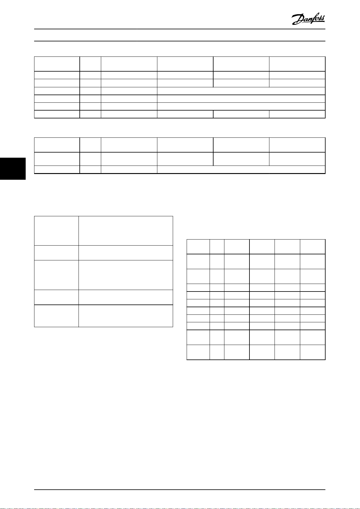
Specications
VLT® Integrated Servo Drive ISD® 510 System
6
Specications Unit Size 1
1.5 Nm
Torque constant KtNm/A 1.10 1.26 1.72 2.04
Inertia
Shaft diameter mm 14 19
Pole pairs – 4 5
Flange size mm 76 84
Weight kg 3.5 4.0 5.0 6.0
Table 6.3 Characteristic Data for Servo Drive without Brake
Specications Unit Size 1
Brake inertia
Brake weight kg 0.34 0.63
Table 6.4 Characteristic Data for Servo Drive with Brake
Kgm
Kgm
2
2
0.000085 0.00015 0.00021 0.00027
1.5 Nm
0.0000012 0.0000068 0.0000068 0.0000068
6.1.4 General Specications and
Size 2
2.1 Nm
Size 2
2.1 Nm
Size 2
2.9 Nm
Size 2
2.9 Nm
6.1.5 Motor Output and Data
Size 2
3.8 Nm
Size 2
3.8 Nm
Environmental Conditions
Table 6.6 shows the nominal load points for the 4 dierent
Vibration test Random vibration: 7.54 g (2h/axis according
to EN 60068-2-64)
Sinusoidal vibration: 0.7 g (2h/axis
according to EN 60068-2-6)
Maximum relative
humidity
Ambient
temperature range
Installation
elevation
EMC standard for
emission and
immunity
Table 6.5 General Specications and Environmental Conditions
for VLT® Integrated Servo Drive ISD 510
Storage/transport: 5–93% (non-condensing)
Stationary use: 15–85% (non-condensing)
5–40 °C above derating, maximum 55 °C
(24-hour average maximum 35 °C)
Transport: -25 to +70 °C
Storage: -25 to +55 °C
Maximum 1000 m above sea level
EN 61800-3
motor sizes. The DC-link voltage is 560 V and the ambient
temperature is 40 °C.
Unit Size 1
1.5 Nm
N_mech_
max
N_n [RPM]4600 4000 2900 2400
M_n [Nm] 1.5 2.1 2.9 3.8
I_n_rms [A] 1.4 1.7 1.7 1.8
P_n [kW] 0.72 0.88 0.88 0.95
M_0 [Nm] 2.3 2.8 3.6 4.6
I_0_rms [A] 2.1 2.3 2.1 2.2
M_0max [Nm] 6.1 7.8 10.7 12.7
I_0max_pk[A] 8.0 9.0 9.0 9.0
I_0max_rms[A] 5.7 6.4 6.4 6.4
[RPM]7000 6000 5000 4000
Size 2
2.1 Nm
Size 2
2.9 Nm
Size 2
3.8 Nm
Table 6.6 Drive Loadpoints with 560 V DC and 40 °C
Ambient Temperature
The following subchapters show:
Speed-torque characteristics
•
Maximum speed related to voltage.
•
58 Danfoss A/S © 08/2017 All rights reserved. MG36C102

M [Nm]
0.00
1.00
2.00
3.00
4.00
5.00
6.00
7.00
0 1000 2000 3000 4000 5000 6000
n [rpm]
2
3
4
1
130BF916.10
0.00
1.00
2.00
3.00
4.00
5.00
6.00
7.00
M [Nm]
0 1000 2000 3000 4000 5000 6000
n [rpm]
2
3
4
1
130BF917.10
0.00
1.00
2.00
3.00
4.00
5.00
6.00
7.00
8.00
9.00
M [Nm]
0 1000 2000 3000 4000 5000
n [rpm]
2
3
4
1
130BF918.10
0.00
1.00
2.00
3.00
4.00
5.00
6.00
7.00
8.00
9.00
M [Nm]
0 1000 2000 3000 4000 5000
n [rpm]
2
3
4
1
130BF919.10
Specications Design Guide
6.1.5.1 Speed-Torque Characteristics: Size 1,
1.5 Nm at 25 °C Ambient
Temperature
1 SOA 680 V
2 S3
3 SOA 560 V
4 S1
Illustration 6.11 Performance at 25 °C Ambient Temperature:
Size 1, 1.5 Nm
6.1.5.3 Speed-Torque Characteristics: Size 2,
2.1 Nm at 25 °C Ambient
Temperature
1 SOA 680 V
2 S3
3 SOA 560 V
4 S1
Illustration 6.13 Performance at 25 °C Ambient Temperature:
Size 2, 2.1 Nm
6
6
6.1.5.2 Speed-Torque Characteristics: Size 1,
1.5 Nm at 40 °C Ambient
Temperature
1 SOA 680 V
2 S3
3 SOA 560 V
4 S1
Illustration 6.12 Performance at 40 °C Ambient Temperature:
Size 1, 1.5 Nm
MG36C102 Danfoss A/S © 08/2017 All rights reserved. 59
6.1.5.4 Speed-Torque Characteristics: Size 2,
2.1 Nm at 40 °C Ambient
Temperature
1 SOA 680 V
2 S3
3 SOA 560 V
4 S1
Illustration 6.14 Performance at 40 °C Ambient Temperature:
Size 2, 2.1 Nm

2
3
4
1
0.00
2.00
4.00
6.00
8.00
10.00
12.00
M [Nm]
0 500 1000 1500 2000 2500 3000 3500 4000
n [rpm]
130BF920.10
0.00
2.00
4.00
6.00
8.00
10.00
12.00
M [Nm]
0 500 1000 1500 2000 2500 3000 3500 4000
n [rpm]
2
3
4
1
130BF921.10
0.00
2.00
4.00
6.00
8.00
10.00
12.00
14.00
M [Nm]
0 500 1000 1500 2000 2500 3000 3500
n [rpm]
2
3
4
1
130BF922.10
0.00
2.00
4.00
6.00
8.00
10.00
12.00
14.00
M [Nm]
0 500 1000 1500 2000 2500 3000 3500
n [rpm]
2
3
4
1
130BF923.10
Specications
VLT® Integrated Servo Drive ISD® 510 System
6
6.1.5.5 Speed-Torque Characteristics: Size 2,
2.9 Nm at 25 °C Ambient
Temperature
1 SOA 680 V
2 S3
3 SOA 560 V
4 S1
Illustration 6.15 Performance at 25 °C Ambient Temperature:
Size 2, 2.9 Nm
6.1.5.7 Speed-Torque Characteristics: Size 2,
3.8 Nm at 25 °C Ambient
Temperature
1 SOA 680 V
2 S3
3 SOA 560 V
4 S1
Illustration 6.17 Performance at 25 °C Ambient Temperature:
Size 2, 3.8 Nm
6.1.5.6 Speed-Torque Characteristics: Size 2,
2.9 Nm at 40 °C Ambient
Temperature
1 SOA 680 V
2 S3
3 SOA 560 V
4 S1
Illustration 6.16 Performance at 40 °C Ambient Temperature:
Size 2, 2.9 Nm
60 Danfoss A/S © 08/2017 All rights reserved. MG36C102
6.1.5.8 Speed-Torque Characteristics: Size 2,
3.8 Nm at 40 °C Ambient
Temperature
1 SOA 680 V
2 S3
3 SOA 560 V
4 S1
Illustration 6.18 Performance at 40 °C Ambient Temperature:
Size 2, 3.8 Nm

i_ph_out / I_ph_out_cont [%]
Installation altitude [m]
0%
0 500 1000 1500 2000 2500 3000 3500 4000
10%
20%
30%
40%
50%
60%
70%
80%
90%
100%
130BF924.10
130BE670.10
Specications Design Guide
6.1.6 Derating
6.1.6.3 Derating using Servo Drives with
Shaft Seals
6.1.6.1 Derating at High Altitude
Illustration 6.19 shows the derating factor when using the
servo drives above 1000 m.
Illustration 6.19 Derating of Phase Output Current versus
Installation Altitude
NOTICE
The components of the VLT® Integrated Servo Drive
ISD 510 System are only approved for installation at
altitudes up to 2000 m above sea level. Products used at
altitudes above 2000 m above sea level means that such
products are accepted “as is”, and that Danfoss disclaims
all warranties of quality, whether express or implied,
including the warranties of merchantability and tness
for particular purpose. For any such products, Danfoss
has no obligation to repair any damage to or defect in
the products, replace the products, or otherwise remedy
the products. Furthermore, Danfoss disclaims any liability
for damage to person or property caused by the
products due to the product being installed at altitudes
above 2000 m above sea level.
Servo drive size Derating
Size 1, 1.5 Nm 15%
Size 2, 2.1 Nm 11%
Size 2, 2.9 Nm 8%
Size 2, 3.8 Nm 4%
Table 6.8 Derating using Servo Drives with Shaft Seals
6.1.6.4 Derating using Servo Drives with
Mechanical Holding Brake
Servo drive size Derating
Size 1, 1.5 Nm 6%
Size 2, 2.1 Nm 5%
Size 2, 2.9 Nm 5%
Size 2, 3.8 Nm 5%
Table 6.9 Derating using Servo Drives with Mechanical Holding Brake
6.1.7 Connection Tightening Torques
Illustration 6.20 and Illustration 6.21 show the xing screws
and mounting of the servo drives.
6
6
6.1.6.2 Derating at High Ambient
Temperature
Servo drive size Temperature derating factor
Size 1, 1.5 Nm
Size 2, 2.1 Nm
Size 2, 2.9 Nm
Size 2, 3.8 Nm
Table 6.7 Derating at High Ambient Temperature
MG36C102 Danfoss A/S © 08/2017 All rights reserved. 61
0.032 Nm/°C
0.048 Nm/°C
0.056 Nm/°C
0.081 Nm/°C
Illustration 6.20 Mounting of Size 1, 1.9 Nm, Size 2, 2.9 Nm,
and Size 2, 3.8 Nm Servo Drives

130BE671.10
20
Fa
Fr
130BE662.10
Specications
VLT® Integrated Servo Drive ISD® 510 System
6.1.8 Installation
6.1.8.1 Allowed Forces
Illustration 6.22 Allowed Forces
6
Illustration 6.21 Mounting of Size 2, 2.1 Nm Servo Drive
NOTICE
Do not machine the shaft.
Do not use the servo drive if the shaft does not match
the coupling arrangement.
Table 6.10 lists the tightening torque values for the xing
screws. Always tighten the xing screws uniformly and
crosswise.
NOTICE
Failure to adhere to the specications in Table 6.10 may
result in damage to the servo drive.
Servo drive size Thread type/
hole size
Size 1, 1.5 Nm
Size 2, 2.1 Nm M6 pitch 1 mm 23 mm 6 Nm
Size 2, 2.9 Nm
Size 2, 3.8 Nm
Table 6.10 Tightening Torques
∅ 5.8 mm
∅ 7 mm
∅ 7 mm
Maximum
thread length
– –
– –
– –
Tightening
torque
NOTICE
The xing screws are not supplied and must be selected
according to the machine xings.
Illustration 6.22 shows the maximum allowed forces on the
motor shaft.
The maximum axial and radial load while assembling the
motor and for any mechanical device connected to the
shaft, must not exceed the values shown in Table 6.11. The
shaft must be loaded slowly and in a constant manner:
Avoid pulsating loads.
NOTICE
The bearing could be permanently damaged if the
maximum allowed forces are exceeded.
Motor size Radial Force (Fr) in N Axial Force (Fa) in N
Size 1 450 1050
Size 2 900 1700
Table 6.11 Permitted Forces
The maximum radial load ratings are based on the
following assumptions:
The servo drives are operated with peak torque
•
of the longest member of the frame size.
Fully reversed load is applied to the end of the
•
smallest diameter standard mounting shaft
extension.
Innite life with standard 99% reliability.
•
Safety factor = 2
•
6.1.8.2 Bearing Load Curves
This section shows the bearing load curves (L10h – 10%
62 Danfoss A/S © 08/2017 All rights reserved. MG36C102
failure) for each servo drive variant, which are calculated
based on DIN ISO281. The curves show the maximum
allowed radial force versus the maximum allowed axial
force on the shaft end for dierent speeds. The estimated
life-span of the bearing with this condition is 20000 h.

0
100
200
300
400
500
0 100 200 300 400 500 600
600
Fa [N]
Fr [N]
130BF946.10
2
3
4
5
6
1
0
100
200
300
400
500
600
700
800
900
1000
1100
1200
0 200 400 600 800 1000 1200
130BF947.10
Fa [N]
Fr [N]
2
3
1
4
5
0
100
200
300
400
500
600
700
800
900
1000
1100
1200
0 200 400 600 800 1000 1200 1400
Fa [N]
Fr [N]
130BF948.10
2
3
4
1
0
100
200
300
400
500
600
700
800
900
1000
1100
1200
0 200 400 600 800 1000 1200 1400
130BF949.10
Fa [N]
Fr [N]
2
4
1
3
Specications Design Guide
Size 1, 1.5 Nm
1 500 RPM
2 1000 RPM
3 2000 RPM
4 3000 RPM
5 4000 RPM
6 5000 RPM
Illustration 6.23 Size 1, 1.5 Nm
Size 2, 2.9 Nm
1 500 RPM
2 1000 RPM
3 2000 RPM
4 3000 RPM
Illustration 6.25 Size 2, 2.9 Nm
Size 2, 3.8 Nm
6
6
Size 2, 2.1 Nm
1 500 RPM
2 1000 RPM
3 2000 RPM
4 3000 RPM
5 4000 RPM
Illustration 6.24 Size 2, 2.1 Nm
MG36C102 Danfoss A/S © 08/2017 All rights reserved. 63
1 500 RPM
2 1000 RPM
3 2000 RPM
4 3000 RPM
Illustration 6.26 Size 2, 3.8 Nm

Specications
VLT® Integrated Servo Drive ISD® 510 System
6
6.1.8.3 Installation Safety and Warnings
General
The machine surface that comes in contact with
•
the servo drive ange must be unpainted to
guarantee good thermal behavior of the servo
drive, and to minimize EMI disturbance in the
servo system.
Do not machine the shaft.
•
Do not use the servo drive if the shaft does not
•
match the coupling arrangement.
Do not hammer the servo and do not use a
•
hammer for tting because this will damage the
equipment.
Ensure that the machinery is at a complete
•
standstill before installing the servo drive.
Ensure that the machinery is at a complete
•
standstill and secured against unintended start
before doing any work on the servo drive, for
example dismounting the servo drive.
During operation, the surface of both motor and
•
electronic housing could reach temperatures of
>100 °C. Ensure that the surface has cooled down
before dismounting the servo drive.
Avoid brute force while dismounting the servo
•
drive and follow the instructions in the VLT
Integrated Servo Drive ISD® 510 System Operating
Instructions.
Before working on the power connector
•
(connecting and disconnecting the M23
connector), disconnect the mains supply and wait
for the discharge time (see chapter 1.6 Safety) to
elapse.
Mount the protection caps for any servo drive
•
connectors that are not in use.
Warnings and notes for servo drive with optional brake
Use an additional, external, mechanical brake to
•
ensure personal safety in case of hanging loads
(vertical axes). If the brake is released, then the
rotor can be moved without remanent torque.
The holding brakes are designed as standstill
•
brakes and are not suitable for repeated
operational braking. Frequent operational braking
results in premature wear and failure of the
holding brake.
Warnings and notes for servo drive with optional shaft
seal
Do not apply any axial load to the shaft seal.
•
Prevent the seal from becoming dry by using
•
adequate lubrication.
®
Harsh environmental conditions, for example
•
frictional heat, dirt, dust, or chemical substances,
can reduce the lifetime of the shaft seal.
Therefore the lifetime depends on the specic
application.
The maintenance task for the shaft seal is
•
explained in Table 6.12.
Maintenance task Maintenance interval Instruction
Check the
condition and
check for leakage
Table 6.12 Maintenance Task: Shaft Seal
Recommended every
4500 hours. A shorter or
longer interval is possible
depending on the
application.
If damaged,
replace the
shaft seal.
64 Danfoss A/S © 08/2017 All rights reserved. MG36C102

190.5
(7.50)
268
(10.55)
371.5
(14.63)
130BE312.10
Specications Design Guide
6.2 SAB
6.2.1 Dimensions
All dimensions are in mm (in).
Front view
6
6
Illustration 6.27 Dimensions: Front View
MG36C102 Danfoss A/S © 08/2017 All rights reserved. 65

246.4
(9.70)
11.5
(0.45)
218.7
(8.61)
130BE313.10
Specications
Side view
VLT® Integrated Servo Drive ISD® 510 System
6
Illustration 6.28 Dimensions: Side View
66 Danfoss A/S © 08/2017 All rights reserved. MG36C102

130BE423.10
130
862
5.5
11
10
110
10
110
6.5
752
Specications Design Guide
Mounting plate
6
6
Illustration 6.29 Dimensions: Mounting Plate
MG36C102 Danfoss A/S © 08/2017 All rights reserved. 67

1
3 4
2
5
6
7
8
9
10
11
12
13
14
17
16
15
18
192021
2224 2325
26
27
28
29
30
33
31
32
130BE387.10
6
Specications
6.2.2 Clearance
The SABs can be mounted next to each other but
•
require a minimum space of 100 mm at the top
and bottom for cooling.
In addition to its own dimensions, the SAB needs
•
100 mm space between the SAB decoupling plate
and the cable duct for connecting cables.
6.2.3 Terminal Locations
VLT® Integrated Servo Drive ISD® 510 System
Illustration 6.30 Explosion Drawing of the Servo Access Box
68 Danfoss A/S © 08/2017 All rights reserved. MG36C102

Specications Design Guide
Number Description/connector name Name on
corresponding
connector
1 Local control panel (LCP) – 18 Hybrid cable line 2 –
2 Front cover – 19 Decoupling plate –
3 STO 1 IN: STO
(Used for STO input voltage 1)
4 STO 1 IN: 24 V
(Used for bridging when the STO function
is not required, see chapter 6.2.3.1 STO
Connectors)
5 LEDs for status of auxiliary output and
STO
6 Decoupling clamp for STO cable – 23 Relay 2 Relay 2
7 ISD Line 2: STO 2
(STO output to hybrid cable line 2)
8 ISD Line 2: NET 2 X4
(Ethernet output to hybrid cable line 2)
9 ISD Line 2: AUX 2
(Auxiliary output to hybrid cable line 2)
10 ISD Line 2: UDC 2
(UDC output to hybrid cable line 2)
11 ISD Line 1: STO 1
(STO output to hybrid cable line 1)
12 ISD Line 1: NET 1 X3
(Ethernet output to hybrid cable line 1)
13 ISD Line 1: AUX 1
(Auxiliary output to hybrid cable line 1)
14 ISD Line 1: UDC 1
(UDC output to hybrid cable line 1)
15 Grounding PE clamp for hybrid cable line2– 32 STO 2 IN: 24 V
16 Grounding PE clamp for hybrid cable line1– 33 Cover –
+STO– 20 Shielded cable grounding
+24V– 21 24/48 V IN
– 22 Relay 1 Relay 1
+STO– 24 Brake R– (81), R+ (82)
RJ45 connector
(without label)
+AUX– 26 Fixture for Ethernet inputs –
+UDC– 27 Decoupling clamp for encoder
+STO– 28 X1
RJ45 connector
(without label)
+AUX– 30 GND, 24 V, GX, /RS422 TXD,
+UDC– 31 STO 2 IN: STO
Number Description/connector name Name on
corresponding
connector
–
clamp and strain relief
+AUX–
(Auxiliary input terminal)
25 Mains
(Input terminal)
cable
(Ethernet input line 1)
29 X2
(Ethernet input line 2)
RS422 TXD, /RS422 RXD, RS422
RXD
(Encoder terminal)
(Used for STO input voltage 2)
(Used for bridging when the
STO function is not required,
see chapter 6.2.3.1 STO
Connectors)
L1 (91), L2 (92), L3
(93)
–
RJ45 connector
(not included)
RJ45 connector
(not included)
Not labeled
+STO–
+24V–
6
6
17 Hybrid cable line 1 – – – –
Table 6.13 Legend to Illustration 6.30
MG36C102 Danfoss A/S © 08/2017 All rights reserved. 69

130BE393.10
+ STO –
130BE396.10
+ 24V –
130BE394.10
+ STO –
130BE388.10
L1 L2 L3
130BE706.10
1
Specications
VLT® Integrated Servo Drive ISD® 510 System
6
6.2.3.1 STO Connectors
Item Position
on SAB
STO
Front Used for STO
1 IN:
STO
STO
Front Used for STO
2 IN:
STO
STO
Front These
1 IN:
24 V
STO
Front
2 IN:
24 V
ISD
Underside Used for STO
Line
1:
STO
1
ISD
Underside Used for STO
Line
2:
STO
2
Description Drawing/
input voltage
1.
input voltage
2.
connectors can
only be used
to make a
bridge to STO
1 IN: STO and
STO 2 IN: STO
if the STO
function is not
required in the
application.
This connector
cannot be
used for any
other function.
output voltage
1.
output voltage
2.
pins
Pins (left
to right):
STO+
STO-
Pins (left
to right):
24+
24-
Pins (left
to right):
STO+
STO-
Ratings
Nominal voltage:
24 V DC ±10%
Nominal current:
Depends on the
number of servo
drives in the
application.
Maximum current:
1 A
Maximum crosssection:
2
1.5 mm
Nominal voltage:
24 V DC ±10%
Nominal current:
1 A
Maximum crosssection:
2
1.5 mm
Nominal voltage:
24 V DC ±10%
Nominal current:
Depends on the
number of servo
drives in the
application.
Maximum current:
1 A
Maximum crosssection:
2
0.5 mm
6.2.3.2 Mains Connectors
Item Description Drawing/
pins
AC mains
supply
Mains PE
(terminal
95)
Table 6.15 Mains Connectors
1 PE screw (terminal 95)
Illustration 6.31 PE Screw
Used to connect
L1/L2/L3
The PE screw is used
to connect the
protective earth, see
Illustration 6.31.
Pins (left to
right):
L1
L2
L3
– Minimum
Ratings
Nominal
voltage:
400–480 V AC
Nominal
current:
12.5 A
Maximum
cross-section:
2
4 mm
cross-section:
2
10 mm
Table 6.14 STO Connectors
70 Danfoss A/S © 08/2017 All rights reserved. MG36C102

88 89 81 82
-DC +DC R- R+
130BE389.10
130BE390.10
RELAY 1
RELAY 2
130BE391.10
130BE392.10
GND
24 V
GX
RS422 TXD
RS422 TXD
RS422 RXD
RS422 RXD
Specications Design Guide
6.2.3.3 Brake Connector
Item Description Drawing/pins Ratings
Brake Used for
connecting a
brake resistor
Nominal
voltage:
565–778 V DC
Maximum brake
current:
–DC (88) = Do not use
+DC (89) = Do not use
R– (81) = Brake –
R+ (82)= Brake +
14.25 A
Maximum crosssection:
4 mm
Table 6.16 Brake Connector
NOTICE
The maximum length of the brake cable is 20 m
(shielded).
6.2.3.4 Relay Connectors
Item Description Drawing/pins Ratings
6.2.3.5 Encoder Connectors
Item Description Drawing/pins Ratings
Encoder
connector
Used to
connect SSI or
BiSS encoders.
Maximum
crosssection:
0.5 mm2.
Pins (left to right
on SAB label):
See
Table 6.19.
RS422 RXD
/RS422 RXD
2
RS422 TXD
/RS422 TXD
GX
6
24 V
6
GND
Table 6.18 Encoder Connectors
NOTICE
The maximum length of the encoder cable is 25 m
(shielded).
Relay1Used for a customer-
dened reaction. For
example, the relay
can be triggered if
the SAB issues a
warning.
Relay
2
Pins (left to
right):
1: Common
2: Normally
open
3: Normally
closed
Pins (left to
right):
4: Common
5: Normally
open
6: Normally
closed
Pin 1: Common
Pin 2: 240 V AC
Pin 3: 240 V AC
Nominal current:
2 A
Maximum crosssection: 2.5 mm
Pin 4: Common
Pin 5: 400 V AC
Pin 6: 240 V AC
Nominal current:
2 A
Maximum crosssection: 2.5 mm
Number Description Notes Rating/
parameter
SSI BiSS
1 RS422 RXD Positive data Bus speed:
2 /RS422 RXD Negative data
3 RS422 TXD Positive clock
2
4 /RS422 TXD Negative clock
SSI: 0.5 Mbit
with 25 m cable
BiSS: Fullls the
RS485 speci-
cation
5 GX Isolated ground
–
If encoders are
powered externally, the
ground of the external
supply must be
connected to GX.
6 24 V
24 V DC ±10%
(used for powering the
encoder)
2
7 GND Ground for pin 6 –
Maximum
current:
250 mA
Table 6.19 Pin Assignment for SSI and BiSS Encoders
Table 6.17 Relay Connectors
MG36C102 Danfoss A/S © 08/2017 All rights reserved. 71

130BE395.10
8
1
130BE398.10
+ AUX –
130BE397.10
+ AUX –
130BE399.10
+ UDC –
Specications
VLT® Integrated Servo Drive ISD® 510 System
6
6.2.3.6 Ethernet Connectors
Connector
name
Ethernet X1 Connection to
Ethernet X2 Connection to
Ethernet X3 Connection to
Ethernet X4 Connection to
Table 6.20 Ethernet Connectors
Description Drawing/pins Ratings
Fulll the
eldbus
100BASE-T
specication
eldbus
Pins:
servo line 1
1: TD+
2: TD–
servo line 2
3: RD+
6: RD–
NOTICE
The maximum length of the X1 and X2 shielded Ethernet
cables is 30 m.
6.2.3.7 AUX Connectors
Connector
name
ISD Line 1:
AUX 1
ISD Line 2:
AUX 2
Description Drawing/
pins
Used to connect
the AUX output
from the SAB to
the hybrid cable.
Pins (left to
right):
AUX+
AUX–
Ratings
Nominal voltage:
24–48 V DC±10%
Nominal current:
Depends on the
number of servo
drives in the
application
Maximum current:
15 A
Maximum crosssection: 2.5 mm
2
NOTICE
The maximum cable length is 3 m.
6.2.3.9 UDC Connectors
Connector
name
ISD Line 1:
UDC 1
ISD Line 2:
UDC 2
Table 6.23 UDC Connectors
6.2.3.10 Hybrid Cable PE
Item Description Drawing/pins Ratings
Hybrid
cable PE
Table 6.24 Hybrid Cable PE
Description Drawing/
Used to connect
the DC-link
voltage from the
SAB to the
hybrid cable.
Used to connect the
PE wire from the
hybrid cable to the
decoupling plate.
Ratings
pins
Nominal voltage:
565–778 V DC
Nominal current:
Pins (left to
right):
UDC+
UDC–
Depends on the
number of servo
drives in the
application
Maximum current:
15 A
Maximum crosssection:
2.5 mm
See callout 15 in
Illustration 6.30.
2
Maximum
crosssection:
2.5 mm
2
Table 6.21 AUX Connectors
6.2.3.8 24/48 V IN Connector
Connector
name
24/48 V IN
Connector
Table 6.22 24/48 V IN Connector
72 Danfoss A/S © 08/2017 All rights reserved. MG36C102
Description Drawing/
pins
Used for 24–
48 V DC input
to the SAB.
Pins (left to
right):
AUX+
AUX–
Ratings
Nominal voltage: 24–
48 V DC ±10%
Nominal current:
Depends on the
number of servo
drives in the
application
Maximum current:
34 A
Maximum crosssection:
2
4 mm

Maximum
I
out
(%)
a
t
T
A
MB
, M A X
Altitude (km)
T
a
t 100% I
out
D
100%
91%
82%
0 K
–5 K
–9 K
1 k m 2 k m 3 k
m
A
MB
, M A X
(K
)
Specications Design Guide
6.2.4 Characteristic Data
Denition Value and unit
Input
Input voltage
Eciency 98.5% at 400 V
Input current 12.5 A continuous
Output
Output voltage
ISD Line 1: UDC 1 & ISD Line 2: UDC 2
Output voltage
ISD Line 1: STO 1 & ISD Line 2: STO 2
Output voltage
ISD Line 1: AUX 1 & ISD Line 2: AUX 2
Output current
ISD Line 1: AUX 1 & ISD Line 2: AUX 2
Output current UDC
Output current
ISD Line 1: STO 1 & ISD Line 2: STO 2
Output power 8 kW at 400 V
Housing
Dimensions (W x H x D) 130 x 268 x 80 mm
Weight 8.3 kg
400–480 V ±10%
20 A intermittent
565–679 V ±10%
24 V ±10%
24–48 V ±10%
1)
15 A
1)
15 A
1)
1 A
9.7 kW at 480 V
6.2.7 Derating
The cooling capability is decreased at lower air pressure.
Below 1000 m altitude no derating is necessary. Above
1000 m, the ambient temperature or the maximum output
current has to be derated.
2)
6
6
Illustration 6.32 Derating SAB
6.2.8 Connection Tightening Torques
Decoupling plate screws: 2 Nm
Table 6.25 Servo Access Box Characteristic Data
1) Depends on the number of servo drives connected in the
application. The current per servo drive is 6.7 mA.
6.2.5 General Specications and
Environmental Considerations
Protection rating IP20 (UL rating: Open type)
Vibration test Random vibration: 1.14 g (2h/axis
according to EN 60068-2-64)
Sinusoidal vibration: 0.7 g (2h/axis
according to EN 60068-2-6)
Maximum relative
humidity
Ambient
temperature range
Installation elevation Maximum 1000 m above sea level
EMC standard for
emission and
immunity
Table 6.26 General Specications and Environmental Conditions
SAB
Storage/transport and stationary use:
5–93% (non-condensing)
5–50 °C operating temperature
(24-hour average maximum 45 °C)
Transport: -25 to +70 °C
Storage: -25 to +55 °C
EN 61800-3
6.2.6 Mains Supply
Refer to chapter 4.4 Mains Input for information on the
mains supply for the SAB.
MG36C102 Danfoss A/S © 08/2017 All rights reserved. 73

130BE658.10
1
2
3
4
5
6
7
8
9
10
Danfoss ISD 510 Hybrid xxxx Cable
Length: xxxx
Ordering no. 175Gxxxx Rev. x.
1 7 5 G 8 9 X X
Specication no. 175Rxxxx Rev. xxx.
Signal rating Ethernet: 2 x 2 x AWG24 300V
yy.mm.dd
Power rating: 5 x 2.5mm 1000V 18A
2
Signal rating: 2 x 0.5mm 300V
2
120°
130BF953.10
Specications
VLT® Integrated Servo Drive ISD® 510 System
6
6.3 Cable
All cables supplied by Danfoss have a nameplate as per
the example in Illustration 6.33.
1 Cable type
2 Ordering code
3 Revision of specication
4 Manufacturing date
5 Length
6 Power rating
7 Signal rating
8 Signal rating for Ethernet
9 Barcode
10 Manufacturer logo
Illustration 6.33 Example of a Cable Nameplate
WARNING
HIGH VOLTAGE
The VLT® Integrated Servo Drive ISD 510 System contains
components that operate at high voltage when
connected to the electrical supply network.
A hazardous voltage is present on the servo drives and
the SAB whenever they are connected to the mains
network.
There are no indicators on the servo drive or SAB that
indicate the presence of mains supply.
Incorrect installation, commissioning, or maintenance can
lead to death or serious injury.
Installation, commissioning, and maintenance
•
must only be performed by qualied personnel.
The interlocking of the hybrid feed-in cable and loop cable
with the servo drive is indicated by the marking OPEN on
the cable connector.
The advanced servo drive is delivered with M8, M12, and
M23 caps. These caps protect the servo drive connectors
during transportation and storage. Furthermore, they are a
part of the IP protection (IP67 for M8 and M12 covers; IP40
for M23 covers) and must remain tted if the respective
connectors are not used. To achieve IP67 on the M23
connector, use the M23 blind cap.
Connector Tightening torque [Nm]
M8 0.2
M12 0.4
M23 0.8
Table 6.27 Tightening Torques
6.3.1 Feed-In Cable
Shielded/
unshielded
Shielded
Table 6.28 Feed-In Cable
1) Maximum 100 m total length for each line of servo drives.
There are 2 types of connector for the feed-in cable:
•
•
See chapter 5.5.1.1 Feed-In Cable for ordering numbers.
Maximum
cable length
1)
40 m
Description
Hybrid cable (overall shield with
additional eldbus and safety
section shield).
M23 angled connector
M23 straight connector
6.3.1.1 Clearances
Illustration 6.35 and Illustration 6.36 show the dimensions of
2 types of M23 cable connectors installed on the servo
drive. A size 2 servo drive is used in this example and the
dimensions of other sizes dier.
The M23 angled connector can be adjusted or tilted up to
120°, as illustrated in Illustration 6.34.
NOTICE
Do not use force to connect or t the connector. This
causes permanent damage to connector and cables.
Before working on the power connector (connecting and
disconnecting M23), disconnect the mains supply and wait
for discharge time to elapse (see chapter 1.6 Safety).
74 Danfoss A/S © 08/2017 All rights reserved. MG36C102
Illustration 6.34 Adjustable Angle of the Angled Connector

200 min
37
112
Rmin
130BF955.10
51.4
Rmin
65.5
80
140 min
130BF951.10
130BE383.10
Specications Design Guide
Each connector type requires specic installation spaces or
area in order to ease the installation and to meet the
minimum allowable bending radius of cable.
NOTICE
Exceeding the minimum allowable bending radius of
cable causes damage on connectors on both the servo
drive and the cable itself.
There are 2 possible types of cable installation. The
minimum allowable bending radius R
lation type is:
Permanently exible: 12 x cable diameter =
•
187.2 mm
Permanently installed: 5 x cable diameter =
•
78 mm
The maximum number of bending cycles is 5 million at 7.5
x cable diameter (15.6 mm).
Illustration 6.35 shows the servo drive with the straight
connector installed on a size 2 servo drive. Illustration 6.36
shows the servo drive with the angled connector installed
on a size 2 servo drive. The illustrations show the
minimum distance from the servo drive to next object, and
the minimum allowable bending radius R
permanently installed cable.
For cable installation, allow the height of the connector
plus an additional 30 mm for the cable.
Required installation distances
The minimum distance is measured from the electronic
housing as this is the same for all motor variants.
Straight connector
The minimum distance for the straight connector is
calculated as follows:
0.5 x cable diameter + connector height + R
+ 112 mm + 78 mm = 197.8 mm ≈ 200 mm
for each instal-
min
for
min
= 7.8 mm
min
Angled connector
The minimum distance for the angled connector is
calculated as follows:
0.5 x cable diameter + connector length measured from
electronic housing + R
= 7.8 mm + 51.4 mm + 78 mm =
min
137.8 mm ≈ 140 mm
Illustration 6.36 Required Installation Distance and Minimum
Bending Radius for M23 Angled Connector
6.3.2 Loop Cable
Shielded/
unshielded
Shielded
Table 6.29 Loop Cable
1) Maximum 100 m total length for each line of servo drives.
Illustration 6.37 Loop Cable
Maximum
cable length
1)
25 m
Description
Hybrid cable (overall shield with
additional eldbus and safety
section shield).
6
6
See chapter 5.5.1.2 Loop Cable for ordering numbers.
See chapter 6.1.2.1 Connectors on the Servo Drives for pin
assignment.
6.3.3 Fieldbus Extension Cable
There are 2 types of eldbus extension cable for ring
redundancy:
M23 angled connector to M12 straight connector
Illustration 6.35 Required Installation Distance and Minimum
Bending Radius for M23 Straight Connector
MG36C102 Danfoss A/S © 08/2017 All rights reserved. 75
•
M23 straight connector to M12 straight connector
•
See chapter 5.5.2 Fieldbus Cables for ordering numbers.

Specications
VLT® Integrated Servo Drive ISD® 510 System
6.3.4 LCP Cable
There are 2 types of cable for the LCP module:
To connect the LCP to the servo drive.
•
To connect the LCP to the SAB.
•
See chapter 5.5.3 LCP Cable for ordering numbers.
6.3.5 Sensor and Encoder Cable
Contact Danfoss for further information regarding cables
for connection to the M8 and M12 connectors. The pin
assignment can be found in chapter 6.1.2.1 Connectors on
the Servo Drives. Always use shielded cables.
6
Maximum length: 25 m (shielded)
•
Maximum cross-section: 0.5 mm
•
2
6.3.6 Ethernet Cable
See chapter 6.2.3.6 Ethernet Connectors for pin assignment.
Specication
Ethernet standard Standard Ethernet (in accordance with IEEE
802.3), 100Base-TX (Fast Ethernet)
Cable type S/FTP (shielded foiled twisted pair), ISO
(IEC 11801 or EN 50173), CAT 5e or 6
Damping 23.2 dB (at 100 Mhz and 100 m each)
Crosstalk damping 24 dB (at 100 Mhz and 100 m each)
Return loss 10 dB (100 m each)
Surge impedance
Maximum cable
length
Table 6.30 Ethernet Cable Recommendations
100 Ω
100 m between switches or network devices
NOTICE
Ground the Ethernet cable through the RJ45 connector.
Do not ground it on the strain relief.
76 Danfoss A/S © 08/2017 All rights reserved. MG36C102

Appendix Design Guide
7 Appendix
7.1 Glossary
A side
The A side is the shaft side of the servomotor.
Ambient temperature
The temperature in the immediate vicinity of the servo
system or component.
Automation Studio™
Automation Studio™ is a registered trademark of B&R. It is
the integrated software development environment for B&R
controllers.
Axial force
The force in newton acting on the rotor axis in the axial
direction.
Bearings
The ball bearings of the servomotor.
Beckho
Beckho® is a registered trademark of and licensed by
Beckho Automation GmbH, Germany.
B&R
Multi-national company, specializing in factory and process
automation software and systems for a wide range of
industrial applications.
B side
The rear side of the servo drive with the plug-and-socket
connectors.
Brake
Mechanical holding brake on the servo drive.
CANopen
CANopen® is a registered community trademark of CAN in
Automation e.V.
CE
European test and certication mark.
CiA DS 402
Device prole for drives and motion control.
CiA® is a registered community trademark of CAN in
Automation e.V.
Clamping set
A mechanical device, which, for example, can be used to
secure gears to a motor shaft.
Connector (M23)
Servo drive hybrid connector.
Cooling
The servo drives are cooled by natural convection (without
fans).
DC-link
Each servo drive has its own DC-link, consisting of
capacitors.
®
®
DC-link voltage
A DC voltage shared by several servo drives connected in
parallel.
DC voltage
A direct constant voltage.
DDS Toolbox
A Danfoss pc software tool used for parameter setting and
diagnostics of the servo drives and the SAB.
EPSG
Ethernet POWERLINK® Standardization Group.
ETG
EtherCAT® Technology Group
EtherCAT
EtherCAT® (Ethernet for Control Automation Technology) is
an open high-performance Ethernet-based
EtherCAT® is registered trademark and patented
technology, licensed by Beckho Automation GmbH,
Germany.
Illustration 7.1 EtherCAT
Ethernet POWERLINK
Ethernet POWERLINK® is a deterministic real-time protocol
for standard Ethernet. It is an open protocol managed by
the Ethernet POWERLINK® Standardization Group (EPSG). It
was introduced by Austrian automation company B&R in
2001.
Feed-in cable
Hybrid connection cable between the SAB and servo drive.
Feedback system
The feedback system measures the rotor position.
Fieldbus
Communication bus between controller and servo axis and
SAB; in general between controller and eld nodes.
Firmware
Software in the unit; runs on the control board.
Function block
Device functionalities are accessible via the engineering
environment software.
IGBT
The insulated-gate bipolar transistor is a 3-terminal
semiconductor device, primarily used as an electronic
switch to combine high eciency and fast switching.
®
eldbus system.
®
Logo
®
7 7
MG36C102 Danfoss A/S © 08/2017 All rights reserved. 77

Appendix
VLT® Integrated Servo Drive ISD® 510 System
Installation elevation
Installation elevation above normal sea level, typically
associated with a derating factor.
ISD
Integrated servo drive.
ISD devices
Refers to both the servo drives and the SAB.
ISD servomotor
Designates the ISD servomotor (without the drive
electronics).
LCP
Local control panel.
Loop cable
Hybrid connection cable between 2 servo drives, with 2
M23 connectors.
M8 connectors
77
Fully functional real-time Ethernet port (X3) on the B side
of the advanced servo drive.
Connector (X5) for connection of the LCP to the B side of
the advanced servo drive.
M12 connector
Connector (X4) for connecting I/O and/or encoder on the B
side of the advanced servo drive.
M23 connectors
Connectors (X1 & X2) for connecting the hybrid feed-in
and loop cables on the B side of the standard and
advanced servo drive.
Motor shaft
Rotating shaft on the A side of the servo motor, typically
without a key groove.
Multi-turn encoder
Describes a digital absolute encoder, in which the absolute
position remains known after several revolutions.
PLC
A programmable logic controller is a digital computer used
for automation of electromechanical processes, such as
control of machinery on factor assembly lines.
PELV
Protected extra low voltage is an electricity supply voltage
in a range which carries a low risk of dangerous electrical
shock.
PLCopen
®
Radial force
The force in newton acting at 90° to the longitudinal
direction of the rotor axis.
RCCB
Residual current circuit breaker.
Resolver
A feedback device for servomotors, typically with 2 analog
tracks (sine and cosine).
Safety (STO)
A servo drive safety circuit that switches o the voltages of
the driver components for the IGBTs.
Scope
Is part of the DDS Toolbox software and is used for
diagnosis. It enables internal signals to be depicted.
Servo Access Box (SAB)
Generates the DC-link supply for the VLT® Integrated Servo
Drive ISD 510 System and can host up to 64 servo drives.
SIL 2
Safety Integrated Level II.
Single-turn encoder
Describes a digital absolute encoder, in which the absolute
position for 1 revolution remains known.
SSI
Synchronous serial interface.
Standstill (servo drive)
Power is on, there is no error in the axis, and there are no
motion commands active on the axis.
STO
Safe Torque
O function. On activation of STO, the servo
drive is no longer able to produce torque in the motor.
TwinCAT
®
TwinCAT® is a registered trademark of and licensed by
Beckho Automation GmbH, Germany. It is the integrated
software development environment for controllers from
Beckho.
U
AUX
Auxiliary supply, provides power to the control electronics
of the servo drives and SAB.
Wireshark
®
Wireshark® is a network protocol analyzer released under
the GNU General Public License version 2.
The name PLCopen® is a registered trademark and,
together with the PLCopen® logos, is owned by the
association PLCopen®. PLCopen® is a vendor and product-
independent worldwide association, that
denes a
standard for industrial control programming.
POU
Program organization unit. This can be a program, function
block, or function.
PWM
Pulse width modulation.
78 Danfoss A/S © 08/2017 All rights reserved. MG36C102

Index Design Guide
Index
A
Aggressive atmospheres.................................................................... 35
Allowed forces....................................................................................... 62
Application examples......................................................................... 32
AUX connectors..................................................................................... 72
AUX power supply................................................................................ 48
Auxiliary power supply....................................................................... 44
Axial load................................................................................................. 62
B
Blind caps................................................................................................ 52
Block diagram
ISD 510 servo drive.......................................................................... 15
Servo Access Box.............................................................................. 15
Brake.......................................................................................................... 51
Brake connector.................................................................................... 71
Brake resistor.......................................................................................... 26
C
Cable specications
Encoder cable.................................................................................... 76
Ethernet cable................................................................................... 76
Feed-in cable (M23).................................................................. 51, 74
Fieldbus cable................................................................................... 52
Fieldbus extension cable............................................................... 75
LCP cable...................................................................................... 52, 76
Loop cable (M23)....................................................................... 52, 75
Nameplate.......................................................................................... 74
Sensor cable................................................................................ 52, 76
Cabling
EtherCAT® with redundancy........................................................ 14
Ethernet POWERLINK® with redundancy................................ 13
For 1 Ethernet POWERLINK® line................................................ 12
For 2 Ethernet POWERLINK® lines.............................................. 12
For more than 1 SAB....................................................................... 13
Maximum cable lengths................................................................ 47
Characteristic data
ISD 510 servo drive.......................................................................... 57
Servo Access Box.............................................................................. 73
Communication
DDS Toolbox...................................................................................... 22
EtherCAT®............................................................................................ 21
Ethernet POWERLINK®.................................................................... 22
Fieldbus............................................................................................... 21
Connectors on the ISD 510 servo drive........................................ 55
Connectors on the Servo Access Box
AUX....................................................................................................... 72
Brake..................................................................................................... 71
Encoder................................................................................................ 71
Ethernet X1–X4................................................................................. 72
Mains.................................................................................................... 70
PE........................................................................................................... 72
Relay.............................................................................................. 29, 71
STO........................................................................................................ 70
UDC....................................................................................................... 72
D
DDS Toolbox
Overview............................................................................................. 22
System requirements...................................................................... 22
User interface.................................................................................... 31
Derating
ISD 510 servo drive.......................................................................... 61
SAB........................................................................................................ 73
Dimensions
ISD 510 servo drive.......................................................................... 53
Servo Access Box.............................................................................. 65
Discharge time...................................................................................... 10
Drive congurator................................................................................ 50
Dust........................................................................................................... 36
E
ELCB........................................................................................................... 40
EMC
Earth leakage current..................................................................... 39
Emission requirements.................................................................. 36
Grounding for electrical safety.................................................... 38
Immunity requirements................................................................ 37
Interference........................................................................................ 39
Motor bearing currents.................................................................. 39
Overview............................................................................................. 36
Touch current.................................................................................... 40
Encoder............................................................................................. 28, 51
Encoder connector............................................................................... 71
Environmental conditions
ISD 510 servo drive.......................................................................... 58
SAB........................................................................................................ 73
EtherCAT®................................................................................................ 21
Ethernet connectors............................................................................ 72
Ethernet POWERLINK®........................................................................ 22
F
Fans in the SAB...................................................................................... 24
Faults......................................................................................................... 29
Feedback................................................................................................. 51
Feed-in cable (M23)............................................................................. 51
Fieldbus.................................................................................................... 21
Fieldbus cable........................................................................................ 52
MG36C102 Danfoss A/S © 08/2017 All rights reserved. 79

Index
VLT® Integrated Servo Drive ISD® 510 System
Flange (customized)............................................................................ 51
Functional safety................................................................................... 16
Fuses.......................................................................................................... 43
G
Gases......................................................................................................... 35
Ground fault protection..................................................................... 24
Grounding
For electrical safety.......................................................................... 38
H
Harmonics............................................................................................... 43
High voltage warning..................................................................... 9, 74
Housing SAB........................................................................................... 73
I
IP
Denition of ratings........................................................................ 41
ISD 510 servo drive.......................................................................... 41
Mounting positions......................................................................... 41
Servo Access Box.............................................................................. 41
IP rating
SAB........................................................................................................ 73
ISD 510 servo drive
Block diagram.................................................................................... 15
ISD 510 servo drive
Acoustic noise................................................................................... 34
Allowed forces................................................................................... 62
Ambient temperature.................................................................... 33
Bearing load curves......................................................................... 62
Characteristic data........................................................................... 57
Connectors......................................................................................... 55
Cooling................................................................................................ 33
Derating............................................................................................... 61
Dimensions........................................................................................ 53
Environmental conditions............................................................ 58
External interfaces........................................................................... 11
Flange sizes........................................................................................ 12
Humidity............................................................................................. 33
Installation safety and warnings................................................ 64
LEDs...................................................................................................... 29
Maintenance...................................................................................... 42
Motor and
Motor grounding............................................................................. 47
Motor output and data.................................................................. 58
Motor selection considerations.................................................. 47
Operating environment................................................................. 33
Options................................................................................................ 47
Overvoltage....................................................................................... 33
Speed-torque characteristics....................................................... 58
Terminal locations............................................................................ 55
Thermal protection......................................................................... 48
Tightening torques.......................................................................... 61
Types..................................................................................................... 50
Vibration and shock........................................................................ 34
X1 & X2 hybrid connectors........................................................... 55
X3 3rd Ethernet connector........................................................... 56
X4 I/O and/or encoder connector.............................................. 56
X5 LCP connector............................................................................. 57
ange sizes................................................................... 12
L
LCP
Cable..................................................................................................... 52
Mounting kit...................................................................................... 52
User interface.................................................................................... 31
LEDs on the ISD 510 servo drive
DRIVE STAT.......................................................................................... 29
Link/ACT X1........................................................................................ 30
Link/ACT X2........................................................................................ 30
Link/ACT X3........................................................................................ 30
NET STAT.............................................................................................. 29
LEDs on the Servo Access Box
Aux 1..................................................................................................... 30
Aux 2..................................................................................................... 30
Link/ACT X1........................................................................................ 30
Link/ACT X2........................................................................................ 31
Link/ACT X3........................................................................................ 31
Link/ACT X4........................................................................................ 31
NET STAT.............................................................................................. 30
SAB STAT.............................................................................................. 30
Safe 1.................................................................................................... 30
Safe 2.................................................................................................... 30
Libraries.................................................................................................... 31
Loop cable M23..................................................................................... 52
80 Danfoss A/S © 08/2017 All rights reserved. MG36C102

Index Design Guide
M
Mains conguration............................................................................ 43
Mains input............................................................................................. 43
Mains transients.................................................................................... 43
Maintenance.......................................................................................... 42
Motor bearing currents...................................................................... 39
Motor output and data....................................................................... 58
Motor selection considerations....................................................... 47
O
Operating environment
General................................................................................................. 35
ISD 510 servo drive.......................................................................... 33
SAB........................................................................................................ 34
Operation
Operating modes............................................................................. 23
Overview............................................................................................. 14
Sequence of operation.................................................................. 15
Switching on the ISD 510 servo system................................... 15
With SAB.............................................................................................. 14
Ordering information
Blind caps............................................................................................ 52
Brake..................................................................................................... 51
Customized ange........................................................................... 51
Feedback devices............................................................................. 51
Feed-in cable..................................................................................... 51
Fieldbus cable................................................................................... 52
ISD 510 servo drive.......................................................................... 50
LCP cable............................................................................................. 52
LCP mounting kit............................................................................. 52
Loop cable.......................................................................................... 52
SAB........................................................................................................ 51
Sensor cable....................................................................................... 52
Shaft seal............................................................................................. 51
P
PC-software............................................................................................ 22
PELV........................................................................................................... 41
Power supply.......................................................................................... 44
POWERLINK®........................................................................................... 22
R
Radial load............................................................................................... 62
Radio frequency interference.......................................................... 41
RCD............................................................................................................ 40
Relay connectors........................................................................... 29, 71
Resolver.................................................................................................... 51
Resources for ISD 510 servo system................................................. 7
Safety
Discharge time.................................................................................. 10
Grounding hazard.............................................................................. 9
High voltage.................................................................................. 9, 74
Instructions and precautions......................................................... 9
Unintended start................................................................................ 9
Sensor cable........................................................................................... 52
Sensors..................................................................................................... 49
Servo Access Box
Acoustic noise................................................................................... 35
Ambient temperature.................................................................... 34
AUX connectors................................................................................ 72
Block diagram.................................................................................... 15
Brake connector............................................................................... 71
Characteristic data........................................................................... 73
Clearance............................................................................................ 68
Cooling................................................................................................ 34
Derating............................................................................................... 73
Dimensions........................................................................................ 65
Eciency...................................................................................... 48, 73
Encoder connector.......................................................................... 71
Environmental conditions............................................................ 73
Ethernet connectors....................................................................... 72
Grounding.......................................................................................... 48
Humidity............................................................................................. 34
Input current...................................................................................... 73
Input voltage..................................................................................... 73
LEDs...................................................................................................... 30
Mains connectors............................................................................. 70
Maintenance...................................................................................... 42
Ordering numbers........................................................................... 51
Output voltage................................................................................. 73
Protection rating.............................................................................. 73
Relay connectors....................................................................... 29, 71
STO connectors................................................................................. 70
Terminal locations............................................................................ 68
Tightening torques.......................................................................... 73
UDC connectors................................................................................ 72
Vibration and shock........................................................................ 35
Weight.................................................................................................. 73
Shaft seal................................................................................................. 51
Short circuit protection...................................................................... 24
Specications
ISD 510 servo drive.......................................................................... 53
Servo Access Box.............................................................................. 65
STO (Safe Torque O)
Application example....................................................................... 20
Characteristic data........................................................................... 21
Connectors......................................................................................... 70
Installation.......................................................................................... 17
Overview............................................................................................. 16
Supply requirements...................................................................... 49
Storage..................................................................................................... 42
Switching on the ISD 510 servo system....................................... 15
System overview................................................................................... 11
S
SAB
Operating environment................................................................. 34
MG36C102 Danfoss A/S © 08/2017 All rights reserved. 81
T
Thermal protection.............................................................................. 24

Index
Tightening torques
ISD 510 servo drive.......................................................................... 61
SAB........................................................................................................ 73
Touch current......................................................................................... 40
TwinCAT® NC Axis................................................................................. 31
VLT® Integrated Servo Drive ISD® 510 System
U
UDC connectors.................................................................................... 72
Unintended start..................................................................................... 9
User interfaces
DDS Toolbox...................................................................................... 31
LCP......................................................................................................... 31
V
Voltage warning............................................................................... 9, 74
W
Warnings
Discharge time.................................................................................. 10
High voltage.................................................................................. 9, 74
Unintended start................................................................................ 9
Weight
Brake..................................................................................................... 58
Servo Access Box.............................................................................. 73
Servo drive.......................................................................................... 58
Wiring........................................................................................................ 12
X
X1 & X2 hybrid connectors................................................................ 55
X3 3rd Ethernet connector................................................................ 56
X4 I/O and/or encoder connector.................................................. 56
X5 LCP connector................................................................................. 57
82 Danfoss A/S © 08/2017 All rights reserved. MG36C102

Index Design Guide
MG36C102 Danfoss A/S © 08/2017 All rights reserved. 83

Danfoss can accept no responsibility for possible errors in catalogues, brochures and other printed material. Danfoss reserves the right to alter its products without notice. This also applies to
products already on order provided that such alterations can be made without subsequential changes being necessary in specications already agreed. All trademarks in this material are property
of the respective companies. Danfoss and the Danfoss logotype are trademarks of Danfoss A/S. All rights reserved.
Danfoss A/S
Ulsnaes 1
DK-6300 Graasten
vlt-drives.danfoss.com
130R0694 MG36C102 08/2017
*MG36C102*
 Loading...