

ENGINEERING TOMORROW
Programming Guide
VLT® Integrated Servo Drive ISD® 510 System
vlt-drives.danfoss.com


Contents Programming Guide
Contents
1 Introduction
1.1 Purpose of the Programming Guide
1.2 Additional Resources
1.3 Copyright
1.4 Software
1.4.1 Software Version 15
1.4.2 Firmware Updates 15
1.5 Approvals and Certications
1.6 Terminology
1.7 Safety
2 Servo Drive Operation
2.1 Overview
2.2 Firmware Update
2.3 Basic Operation
2.3.1 State Machine 19
2.3.2 Factor Group 21
2.3.3 Positions and Osets 22
15
15
15
15
15
15
16
16
18
18
18
19
2.3.4 Position Limits 22
2.3.4.1 Hardware Limit Switch 22
2.3.4.2 Software Position Limit 22
2.3.5 Brake Handling 24
2.3.6 Control Loops 24
2.3.6.1 Position Controller 25
2.3.6.2 Speed Controller 26
2.3.6.3 Current Controller 26
2.4 Operating Modes
2.4.1 Prole Position Mode 26
2.4.2 Prole Velocity Mode 30
2.4.3 Prole Torque Mode 32
2.4.4 Homing Mode 33
2.4.4.1 Homing on Actual Position 35
2.4.4.2 Homing on Positive/Negative Block 36
2.4.4.3 Homing on Positive/Negative Limit Switch 36
2.4.4.4 Homing on Positive/Negative Home Switch 37
26
2.4.4.5 Homing on Current Position 37
2.4.4.6 Error Behavior in Homing Mode 38
2.4.5 CAM Mode 38
2.4.5.1 Activating a CAM prole 40
MG36D102 Danfoss A/S © 01/2017 All rights reserved. 1

Contents
VLT® Integrated Servo Drive ISD® 510 System
2.4.5.2 CAM Conguration: Master Absolute/Relative 41
2.4.5.3 CAM Header Information 41
2.4.5.4 Basic CAM 43
2.4.5.5 Advanced CAM 52
2.4.5.6 Commands During Operation 75
2.4.5.7 Notications from the Servo Drive 76
2.4.6 Gear Mode 77
2.4.7 ISD Inertia Measurement Mode 77
2.4.8 Cyclic Synchronous Position Mode 78
2.4.9 Cyclic Synchronous Velocity Mode 78
2.5 Motion Functions
2.5.1 Digital CAM Switch 79
2.5.2 ISD Touch Probe 82
2.5.2.1 Touch Probe Window 83
2.5.2.2 Touch Probe Edge Counter for Continuous Mode 83
2.5.2.3 Timing Example 84
2.5.3 Guide Value 85
2.5.3.1 Guide Value Reference 85
2.5.3.2 Guide Value Reference Simulation 85
2.6 Peripherals
2.6.1 Inputs 86
2.6.2 Output 86
2.6.3 External Encoder 86
2.7 Monitoring
2.7.1 Errors and Warnings 86
2.7.2 Trace 86
2.7.3 Following Error Detection 87
79
86
86
2.7.4 Standstill Detection 87
2.7.5 Constant Velocity Detection 88
2.7.6 STO and Brake Status 88
3 Servo Access Box (SAB) Operation
3.1 Overview
3.2 Control
3.2.1 Relay Outputs 91
3.3 Monitoring
3.3.1 AUX Output 92
3.3.2 DC Output 92
3.3.3 Brake Control and Monitoring 92
3.3.4 Input Voltages 93
3.3.5 Temperatures 93
2 Danfoss A/S © 01/2017 All rights reserved. MG36D102
89
89
90
92

Contents Programming Guide
3.3.6 Cooling Fans 93
3.4 External Encoder and Guide Value
3.5 Signal Tracing
3.6 Multiple Device ID Assignment
3.7 Software Version
3.8 Firmware Update
4 Local Control Panel (LCP) Operation
4.1 Overview
4.2 Local Control Panel (LCP) Layout
4.3 Graphical User Interface
4.3.1 Supported Languages 96
4.3.2 LCP Display 96
4.3.3 Status Menu (Auto On Mode) 96
4.3.3.1 Default Readouts for ISD 510 Servo Drive 97
4.3.3.2 Default Readouts for SAB 97
4.3.3.3 Alarms and Warnings 98
4.3.4 Main Menu 98
4.3.4.1 Displaying and Editing Values 99
93
93
93
93
93
94
94
94
96
4.3.4.2 ISD 510 Drive Menu 100
4.3.4.3 SAB Menu 100
4.3.5 Hand On Mode 101
4.3.5.1 Servo Drive 101
4.3.5.2 SAB 104
4.3.6 Alarm Log 104
4.4 Keys
4.4.1 Status Key 104
4.4.2 Quick Menu Key 104
4.4.3 Main Menu Key 104
4.4.4 Alarm Log Key 105
4.4.5 Back Key 105
4.4.6 Cancel Key 105
4.4.7 Info Key 105
4.4.8 OK Key 106
4.4.9 Hand On Key 106
4.4.10 O Key 106
104
4.4.11 Auto On Key 106
4.4.12 Reset Key 106
4.4.13 Up [▲] and Down [▼] Keys
4.4.14 Left [◀] and Right [▶] Keys
MG36D102 Danfoss A/S © 01/2017 All rights reserved. 3
106
107

Contents
VLT® Integrated Servo Drive ISD® 510 System
4.5 LCP-specic Parameters
4.5.1 ISD 510 Servo Drive-specic LCP Parameters 107
4.5.2 SAB-specic LCP Parameters 108
5 Operation with ISD Toolbox
5.1 Overview
5.2 ISD Toolbox Installation
5.2.1 System Requirements 109
5.2.2 Installation 109
5.3 ISD Toolbox Communication
5.3.1 Network Settings for Indirect Communication 110
5.3.2 Network Settings for Direct Communication with Ethernet POWERLINK
5.3.3 Network Settings for Direct Communication with EtherCAT
5.4 ISD Toolbox Commissioning
5.5 Look and Feel
5.5.1 Main Window 114
5.5.2 Device Environment Window 116
5.5.2.1 Device Information Window 116
107
109
109
109
109
®
®
111
112
112
113
5.5.3 Watchlist Window 118
5.5.4 Output Window 118
5.5.5 Project File 119
5.5.6 Importing and Exporting Devices 119
5.5.7 Online Help 119
5.5.8 Options Window 119
5.6 Connection and Devices
5.6.1 Connect to Bus 121
5.6.2 Disconnect from Bus 121
5.6.3 Online/Oine Devices 121
5.6.4 Adding/Removing Devices 121
5.6.5 Scan for Devices 122
5.7 Sub-Tools
5.7.1 Parameter List (Servo Drive and SAB) 122
5.7.2 Firmware Update (Single and Multi-device for Servo Drive and SAB) 124
5.7.2.1 Single Device Firmware Update 124
5.7.2.2 Multi-Device Firmware Update 124
121
122
5.7.3 Scope (Single and Multi-device for Servo Drive and SAB) 125
5.7.3.1 Sampling 125
5.7.3.2 Triggering 126
5.7.3.3 Trace Signals 127
5.7.3.4 Status 128
4 Danfoss A/S © 01/2017 All rights reserved. MG36D102

Contents Programming Guide
5.7.3.5 Running a Trace 128
5.7.3.6 Polling 129
5.7.3.7 Canceling a Trace 129
5.7.3.8 Trace Visualization 129
5.7.3.9 Saving and Loading Data 130
5.7.3.10 Online and Oine Mode 131
5.7.3.11 Reports, Document Exporting, and Printing 131
5.7.3.12 Multi-device Scope 131
5.7.4 Drive Control (Servo Drive only) 132
5.7.5 Get Error History (Servo Drive and SAB) 136
5.7.6 Digital CAM Switch (Servo Drive only) 137
5.7.7 CAM Editor (Servo Drive only) 138
5.7.7.1 Menu Bar 138
5.7.7.2 Property Window 141
5.7.7.3 Toolbar 141
5.7.7.4 Wizards 141
5.7.7.5 CAM Prole Window Overview 143
5.7.7.6 Editing Basic CAM Proles 144
5.7.7.7 Editing Advanced CAM Proles 146
5.7.7.8 Standalone Emulation of the CAM Editor 157
5.7.8 CAM Prole Management 157
5.7.9 Touch Probe (Servo Drive only) 158
5.7.10 SAB Control (SAB only) 158
5.7.11 SAB ID Assignment via Ethernet POWERLINK® (SAB only) 159
6 Programming
6.1 ID Assignment
6.1.1 EtherCAT
6.1.2 Ethernet POWERLINK
6.1.2.1 Single Device ID Assignment 161
6.1.2.2 Multiple Device ID Assignment 161
6.2 Basic Programming
6.3 TwinCAT
6.3.1 Programming with TwinCAT
161
161
®
®
161
161
161
®
®
162
162
6.3.1.1 ISD Deliverables 162
6.3.1.2 Creating a TwinCAT® Project 162
6.3.1.3 Conguration as a TwinCAT® NC Axis 167
6.3.1.4 Connecting to the PLC 167
6.4 Automation Studio™
6.4.1 Programming with Automation Studio™
MG36D102 Danfoss A/S © 01/2017 All rights reserved. 5
168
168

Contents
VLT® Integrated Servo Drive ISD® 510 System
6.4.1.1 Requirements 168
6.4.1.2 Creating an Automation Studio™ Project
6.4.1.3 Connecting to the PLC 172
6.5 Function Block Descriptions
6.5.1 Overview PLCopen
®
6.5.1.1 Naming Conventions 172
6.5.1.2 Structure of Library/Package 172
6.5.1.3 PLCopen® State Machine 172
6.5.2 General Input/Output Behavior 174
6.5.2.1 Function Blocks with Execute Input 174
6.5.2.2 Function Blocks with Enable Input 175
6.5.2.3 Error Indication 175
6.5.2.4 Technical Units in the PLC library 176
6.5.3 Programming Guidelines 176
6.5.4 Drive – Administrative 177
6.5.4.1 AXIS_REF_ISD51x 177
6.5.4.2 MC_Power_ISD51x 177
6.5.4.3 MC_Reset_ISD51x 178
168
172
172
6.5.4.4 MC_ReadStatus_ISD51x 179
6.5.4.5 MC_ReadAxisError_ISD51x 179
6.5.4.6 DD_ReadAxisWarning_ISD51x 180
6.5.4.7 DD_ReadVersion_ISD51x 180
6.5.4.8 DD_UpdateFirmware_ISD51x 181
6.5.4.9 MC_ReadAxisInfo_ISD51x 182
6.5.4.10 MC_ReadMotionState_ISD51x 182
6.5.4.11 MC_ReadActualPosition_ISD51x 183
6.5.4.12 MC_ReadActualVelocity_ISD51x 183
6.5.4.13 MC_ReadActualTorque_ISD51x 184
6.5.4.14 MC_ReadDigitalInput_ISD51x 185
6.5.4.15 DD_ReadAnalogInput_ISD51x 185
6.5.4.16 MC_ReadDigitalOutput_ISD51x 186
6.5.4.17 DD_WriteDigitalOutput_ISD51x 186
6.5.4.18 MC_ReadParameter_ISD51x and MC_ReadBoolParameter_ISD51x 187
6.5.4.19 DD_ReadParameter4_ISD51x 188
6.5.4.20 DD_ReadParameter_ISD51x 189
6.5.4.21 MC_WriteParameter_ISD51x 189
6.5.4.22 DD_WriteParameter_ISD51x 190
6.5.4.23 DD_WriteParameter4_ISD51x 190
6.5.4.24 DD_Trace_ISD51x 191
6.5.4.25 DD_BrakeHandling_ISD51x 193
6 Danfoss A/S © 01/2017 All rights reserved. MG36D102

Contents Programming Guide
6.5.4.26 DD_SelectControlParamSet_ISD51x 193
6.5.4.27 MC_TouchProbe_ISD51x 194
6.5.4.28 MC_AbortTrigger_ISD51x 195
6.5.4.29 DD_PrepareDigCamSwitch_ISD51x 195
6.5.4.30 DD_DigitalCamSwitch_ISD51x 196
6.5.4.31 DD_ProduceGuideValue_ISD51x 197
6.5.5 Drive – Motion 197
6.5.5.1 MC_Home_ISD51x 197
6.5.5.2 MC_Stop_ISD51x 200
6.5.5.3 MC_Halt_ISD51x 201
6.5.5.4 MC_MoveAbsolute_ISD51x 202
6.5.5.5 MC_MoveRelative_ISD51x 205
6.5.5.6 MC_MoveAdditive_ISD51x 207
6.5.5.7 MC_MoveVelocity_ISD51x 209
6.5.5.8 MC_TorqueControl_ISD51x 209
6.5.5.9 MC_GearIn_ISD51x 210
6.5.5.10 MC_GearInPos_ISD51x 210
6.5.5.11 DD_GetInertia_ISD51x 212
6.5.6 Drive – CAM Operation 212
6.5.6.1 MC_CamTableSelect_ISD51x 212
6.5.6.2 MC_CamIn_ISD51x 213
6.5.6.3 DD_CamScaling_ISD51x 214
6.5.6.4 DD_SetFollowSegment_ISD51x 215
6.5.6.5 DD_SetSegmentParameter_ISD51x 216
6.5.6.6 DD_RotationStop_ISD51x 216
6.5.6.7 DD_NodeNotication_ISD51x 217
6.5.6.8 DD_GoToSetpoint_ISD51x 217
6.5.6.9 DD_ReadCamInfo_ISD51x 218
6.5.7 Drive – CAM Creation 218
6.5.7.1 Basic CAM 218
6.5.8 SAB 221
6.5.8.1 SAB_REF 221
6.5.8.2 DD_Power_SAB 221
6.5.8.3 DD_Reset_SAB 222
6.5.8.4 DD_ReadSabInfo_SAB 222
6.5.8.5 DD_ReadSabError_SAB 223
6.5.8.6 DD_ReadSabWarning_SAB 223
6.5.8.7 DD_ReadVersion_SAB 224
6.5.8.8 DD_UpdateFirmware_SAB 224
6.5.8.9 DD_ReadDcLinkPower_SAB 225
MG36D102 Danfoss A/S © 01/2017 All rights reserved. 7

Contents
VLT® Integrated Servo Drive ISD® 510 System
6.5.8.10 DD_ReadDcLinkVoltage_SAB 225
6.5.8.11 DD_ReadParameter4_SAB 226
6.5.8.12 DD_ReadParameter_SAB 226
6.5.8.13 DD_WriteParameter4_SAB 227
6.5.8.14 DD_WriteParameter_SAB 228
6.5.8.15 DD_Trace_SAB 228
6.5.8.16 DD_SimulateGuideValue_SAB 229
6.5.8.17 DD_ReadPosGuideValueRef_SAB 230
6.5.8.18 DD_ReadVelGuideValueRef_SAB 231
6.6 Simple Programming Template
7 Servo Drive Parameter Description
7.1 Overview
7.2 Controlword Object
7.2.1 Parameter 16-00 Controlword (0x6040) 232
7.2.1.1 Controlword in Prole Position Mode 233
7.2.1.2 Controlword in Prole Velocity Mode 234
7.2.1.3 Controlword in Prole Torque Mode 234
7.2.1.4 Controlword in Homing Mode 235
7.2.1.5 Controlword in CAM Mode 235
7.2.1.6 Controlword in Gear Mode 236
7.2.1.7 Controlword in ISD Inertia Measurement Mode 236
7.2.1.8 Controlword in Cyclic Synchronous Position Mode 236
7.2.1.9 Controlword in Cyclic Synchronous Velocity Mode 237
7.3 Statusword Object
7.3.1 Parameter 16-03 Statusword (0x6041) 237
7.3.1.1 Statusword in Prole Position Mode 239
231
232
232
232
237
7.3.1.2 Statusword in Prole Velocity Mode 239
7.3.1.3 Statusword in Prole Torque Mode 240
7.3.1.4 Statusword in Homing Mode 240
7.3.1.5 Statusword in CAM Mode 241
7.3.1.6 Statusword in Gear Mode 241
7.3.1.7 Statusword in ISD Inertia Measurement Mode 242
7.3.1.8 Statusword in Cyclic Synchronous Position Mode 242
7.3.1.9 Statusword in Cyclic Synchronous Velocity Mode 243
7.4 Factor Group Objects
7.4.1 Parameters 55-00 and 55-01: Position Encoder Resolution (0x608F) 243
7.4.2 Parameters 55-10 and 55-11: Gear Ratio (0x6091) 244
7.4.3 Parameters 55-20 and 55-21: Feed Constant (0x6092) 245
7.4.4 Parameters 55-30 and 55-31: Velocity Factor (0x6096) 246
7.4.5 Parameters 55-40 and 55-41: Acceleration Factor (0x6097) 246
8 Danfoss A/S © 01/2017 All rights reserved. MG36D102
243

Contents Programming Guide
7.5 Commonly Used Objects
7.5.1 Parameter 52-00: Modes of Operation (0x6060) 247
7.5.2 Parameter 52-01: Modes of Operation Display (0x6061) 248
7.5.3 Parameter: Supported Drive Modes (0x6502) 248
7.5.4 Parameter 50-16: Maximum Prole Velocity (0x607F) 249
7.5.5 Parameter 52-37: Maximum Motor Speed (0x6080) 249
7.5.6 Parameter 52-12: Prole Velocity (0x6081) 250
7.5.7 Parameter 50-11: Prole Acceleration (0x6083) 250
7.5.8 Parameter 50-12: Prole Deceleration (0x6084) 251
7.5.9 Parameter 50-13: Quick Stop Deceleration (0x6085) 251
7.5.10 Parameter 50-14: Maximum Acceleration (0x60C5) 252
7.5.11 Parameter 50-15: Maximum Deceleration (0x60C6) 252
7.5.12 Parameter: Maximum Torque (0x6072) 253
7.5.13 Parameters 52-15, 52-23, and 52-36: Application Torque Limit (0x2053) 253
7.6 Control Parameters
7.6.1 Parameter 51-07 to 51-09: Used Task Cycle Times (0x201D) 254
7.6.2 Parameter 51-01: Control Parameter Blending Time (0x201B) 255
247
254
7.6.3 Parameter 51-00: Control Parameter Usage (0x201C) 255
7.6.4 Position Controller 255
7.6.4.1 Parameters 51-16 and 51-17: Position Controller Parameters (0x2013) 255
7.6.4.2 Parameters 51-26 and 51-27: Position Controller Parameters 2 (0x2015) 256
7.6.5 Speed Controller 257
7.6.5.1 Parameters 51-10 to 51-15: Speed Controller Parameters (0x2012) 257
7.6.5.2 Parameters 51-20 to 51-25: Speed Controller Parameters 2 (0x2014) 258
7.7 Positions and Oset Objects
7.7.1 Parameter: Position Demand Value (0x6062) 260
7.7.2 Parameter: Position Demand Internal Value (0x60FC) 260
7.7.3 Parameter: Drive Position (0x2022) 261
7.7.4 Parameter: Position Actual Internal Value (0x6063) 261
7.7.5 Parameter 50-03: Position Actual Value (0x6064) 262
7.7.6 Parameters 50-30 and 50-31: Position Range Limit (0x607B) 262
7.7.7 Parameters 50-32 and 50-33: Software Position Limit (0x607D) 263
7.7.8 Parameters 51-02, 52-04, and 52-49: Application Settings (0x2016) 264
7.8 Guide Value Objects
260
265
7.8.1 Parameter: Position Guide Value (0x2060) 265
7.8.2 Parameter: Velocity Guide Value (0x2064) 266
7.8.3 Parameter: Guide Value Option Code (0x2061) 266
7.8.4 Parameter: Guide Value Scaling Factor (0x3808) 267
7.8.5 Parameter: Guide Value Oset (0x3806) 268
7.9 Guide Value Reference Objects
MG36D102 Danfoss A/S © 01/2017 All rights reserved. 9
269

Contents
VLT® Integrated Servo Drive ISD® 510 System
7.9.1 Parameter: Position Guide Value Reference (0x2062) 269
7.9.2 Parameter: Velocity Guide Value Reference (0x2065) 269
7.9.3 Parameter: Guide Value Reference Option Code (0x2063) 269
7.9.4 Parameter: Position Guide Value Reference Set (0x2068) 270
7.9.5 Parameter: Guide Value Plausibility Distance (0x2067) 271
7.9.6 Guide Value Reference Simulation 271
7.9.6.1 Parameter: Guide Value Reference Simulation Control (0x2070) 271
7.9.6.2 Parameter: Guide Value Reference Speed Limit (0x2071) 272
7.9.6.3 Parameter: Guide Value Reference Target Velocity (0x2072) 272
7.9.6.4 Parameter: Guide Value Reference Acceleration (0x2073) 272
7.9.6.5 Parameter: Guide Value Reference Deceleration (0x2074) 273
7.10 Prole Position Mode Objects
7.10.1 Parameter 52-10: Target Position (0x607A) 273
7.10.2 Parameter 52-16: End Velocity (0x6082) 274
7.10.3 Parameter: Positioning Option Code (0x60F2) 274
7.10.4 Parameter: Position Window (0x6067) 277
7.10.5 Parameter: Position Window Time (0x6068) 277
7.11 Prole Velocity Mode Objects
7.11.1 Parameter 52-20: Target Velocity (0x60FF) 277
7.11.2 Parameter: Velocity Demand Value (0x606B) 278
7.11.3 Parameter 50-04: Velocity Actual Value (0x606C) 278
7.11.4 Parameter: Velocity Window (0x606D) 279
7.11.5 Parameter: Velocity Window Time (0x606E) 279
7.12 Prole Torque Mode Objects
7.12.1 Parameter 52-30: Target Torque (0x6071) 279
7.12.2 Parameter: Torque Demand (0x6074) 280
7.12.3 Parameter 50-20: Motor Rated Current (0x6075) 280
7.12.4 Parameter 50-21: Motor Rated Torque (0x6076) 280
273
277
279
7.12.5 Parameter 52-31: Torque Actual Value (0x6077) 281
7.12.6 Parameter 16-14: Current Actual Value (0x6078) 281
7.12.7 Parameter 52-32: Torque Slope (0x6087) 282
7.12.8 Parameter: Torque Window (0x2050) 282
7.12.9 Parameter: Torque Window Time (0x2051) 282
7.13 Homing Mode Objects
283
7.13.1 Parameter 52-40: Home Oset (0x607C) 283
7.13.2 Parameter 52-41: Homing Method (0x6098) 283
7.13.3 Parameters 52-42 and 52-43: Homing Speeds (0x6099) 284
7.13.4 Parameter 52-44: Homing Acceleration (0x609A) 284
7.13.5 Parameter 52-50 to 52-57: Supported Homing Methods (0x60E3) 285
7.13.6 Parameter 52-45 to 52-48: Additional Homing objects (0x2040) 287
10 Danfoss A/S © 01/2017 All rights reserved. MG36D102

Contents Programming Guide
7.14 CAM Mode Objects
7.14.1 Parameter: CAM Prole Memory Layout (0x380F) 288
7.14.2 Parameter: CAM Status (0x3801) 289
7.14.3 Parameter: CAM Control (0x3800) 290
7.14.4 Parameters: CAM Prole 1–8 (0x3810–0x3817) 291
7.14.5 Parameters: CAM Data 1–8 (0x3820–3827) 301
7.14.6 Parameters: CAM Pattern 1–8 (0x3830–3837) 301
7.14.7 Parameter: CAM Prole Selector (0x3804) 302
7.14.8 Parameter: CAM Prole Status (0x3805) 303
7.14.9 Parameter: CAM Slave Oset (0x3807) 304
7.14.10 Parameter: CAM Slave Scaling (0x3809) 305
7.14.11 Parameter: Minimum Blending Distance (0x380A) 306
7.14.12 Parameter: Logical CAM Position (0x2020) 307
7.14.13 Parameter: Logical CAM Set Point (0x2021) 307
7.14.14 Parameter: Active Segment ID (0x2019) 307
7.14.15 Parameter: Last Node ID (0x201A) 308
7.14.16 Parameter: Logged Values (0x3870) 308
288
7.14.17 Parameter: Digital Input Counters (0x3860) 309
7.15 Gear Mode Objects
7.15.1 Parameter: Gear Ratio (0x3900) 309
7.15.2 Parameter: Gear Synchronization Option Code (0x3901) 310
7.15.3 Parameter: Gear Master Start Distance (0x3902) 311
7.15.4 Parameter: Gear Master Sync Position (0x3903) 312
7.15.5 Parameter: Gear Slave Sync Position (0x3904) 312
7.16 ISD Inertia Measurement Objects
7.16.1 Parameter 52-60: Measured Inertia (0x2009) 313
7.16.2 Parameters 52-61 and 52-62: Inertia Measurement Parameters (0x200A) 314
7.17 Digital CAM Switch Objects
7.17.1 Parameter: On Compensation (0x3840) 314
7.17.2 Parameter: O Compensation (0x3841) 315
7.17.3 Parameter: Hysteresis (0x3842) 315
7.17.4 Parameters: Digital CAM Switch Parsing Control (0x3843) 316
7.17.5 Parameter: Digital CAM Switches Data (0x3844) 318
7.18 Touch Probe Objects
309
313
314
318
7.18.1 Parameter: Touch Probe Function (0x60B8) 318
7.18.2 Parameter: Touch Probe Status (0x60B9) 319
7.18.3 Parameter 51-51: Touch Probe 1 Positive Edge (0x60BA) 320
7.18.4 Parameter 51-54: Touch Probe 1 Negative Edge (0x60BB) 321
7.18.5 Parameter 51-61: Touch Probe 2 Positive Edge (0x60BC) 321
7.18.6 Parameter 51-64: Touch Probe 2 Negative Edge (0x60BD) 321
MG36D102 Danfoss A/S © 01/2017 All rights reserved. 11

Contents
VLT® Integrated Servo Drive ISD® 510 System
7.18.7 Parameters 51-50 and 51-60: Touch Probe Source (0x60D0) 322
7.18.8 Parameter: First Position (0x3853) 322
7.18.9 Parameter: Last Position (0x3854) 323
7.18.10 Parameter 51-53: Touch Probe Time Stamp 1 Positive Value (0x60D1) 324
7.18.11 Parameter 51-56: Touch Probe Time Stamp 1 Negative Value (0x60D2) 324
7.18.12 Parameter 51-63: Touch Probe Time Stamp 2 Positive Value (0x60D3) 324
7.18.13 Parameter 51-66: Touch Probe Time Stamp 2 Negative Value (0x60D4) 325
7.18.14 Parameter 51-52: Touch Probe 1 Positive Edge Counter (0x60D5) 325
7.18.15 Parameter 51-55: Touch Probe 1 Negative Edge Counter (0x60D6) 326
7.18.16 Parameter 51-62: Touch Probe 2 Positive Edge Counter (0x60D7) 326
7.18.17 Parameter 51-65: Touch Probe 2 Negative Edge Counter (0x60D8) 327
7.19 Tracing Objects
7.19.1 Parameter: Signal Tracer Control (0x5000) 327
7.19.2 Parameter: Signal Trace Channel IDs (0x5001) 329
7.19.3 Parameter: Trace Data (0x5002) 330
7.19.4 Parameter: Trace Signal Info (0x5004) 330
7.20 Option Code Objects
7.20.1 Parameter 50-41: Fault Reaction Option Code (0x605E) 331
7.20.2 Parameter 50-42: Target Reached Option Code (0x2054) 331
7.20.3 Parameter 50-43: Following Error Option Code (0x2055) 332
7.20.4 Parameter 50-44: Enable in Positioning Option Code (0x2052) 333
7.20.5 Parameter 50-45: Abort Connection Option Code (0x6007) 333
7.20.6 Parameter 50-46: Quick Stop Option Code (0x605A) 334
7.20.7 Parameter 50-47: Halt Option Code (0x605D) 334
7.20.8 Parameter 50-48: Shutdown Option Code (0x605B) 335
7.20.9 Parameter 50-49: Disable Operation Option Code (0x605C) 335
7.21 Peripherals
7.21.1 Parameter 16-60: Digital Inputs (0x60FD) 336
327
331
336
7.21.2 Parameters 16-62 and 16-64: Analog Inputs (0x200D) 337
7.21.3 Parameter: Dual Analog User Inputs Conguration (0x200F) 337
7.21.4 Parameter 16-66: Digital Outputs (0x60FE) 338
7.21.5 Parameter 52-05: Digital Output Conguration (0x2FFF) 339
7.21.6 External Encoder Objects 340
7.21.6.1 Parameters 51-30 and 51-34 to 51-40: External Encoder Conguration
(0x3000) 340
7.21.6.2 Parameter 51-32 and 51-33: External Encoder (0x2011) 342
7.21.6.3 Parameter 51-31: External Encoder Enable (0x3001) 343
7.22 Monitoring Objects
343
7.22.1 Following Error Detection Objects 343
7.22.1.1 Parameter: Following Error Window (0x6065) 343
12 Danfoss A/S © 01/2017 All rights reserved. MG36D102

Contents Programming Guide
7.22.1.2 Parameter: Following Error Time Out (0x6066) 344
7.22.1.3 Parameter: Following Error Actual Value (0x60F4) 344
7.22.2 Standstill Detection Objects 345
7.22.2.1 Parameter: Velocity Threshold (0x606F) 345
7.22.2.2 Parameter: Velocity Threshold Time (0x6070) 345
7.22.3 Constant Velocity Detection Objects 346
7.22.3.1 Parameter 51-70: Constant Velocity Window (0x2030) 346
7.22.3.2 Parameter 51-71: Constant Velocity Window Time (0x2031) 346
7.22.4 Parameters 15-40, 15-41, and 15-43: Version log (0x4000) 346
7.22.5 Parameter 15-51: Serial String (0x4004) 348
7.22.6 Parameters 12-00 to 12-05: Communication Settings (0x400A) 349
7.22.7 Parameters 15-01 and 15-02: Total Running Time (0x5807) 350
7.22.8 Parameter 50-09: STO Voltage and Brake Status (0x2007) 351
7.22.9 Parameter 15-30: Error Code (0x603F) 352
7.22.10 Parameter 16-92: Warning Code (0x5FFE) 352
7.22.11 Parameter: Control Source (0x5020) 352
7.22.12 Parameter 50-08: Motion and Input Status (0x2006) 353
7.22.13 Parameter 50-07: Overlaying Motion Status (0x2005) 354
7.22.14 Parameter: Physical Limits (0x5100) 354
7.22.15 Voltage Objects 356
7.22.15.1 Parameter 16-30: DC Link Voltage (0x2003) 356
7.22.15.2 Parameter 50-06: Auxiliary Voltage (0x200E) 356
7.22.16 Parameter 16-19, 16-31, 16-34, 16-39: Temperature (0x2000) 356
8 SAB Parameter Description
8.1 Object 0x4040: Controlword
8.2 Object 0x4041: Statusword
8.3 Object 0x2000: SAB Temperatures
8.4 Object 0x2001: DC-link Related Values
8.5 Object 0x2003: U
8.6 Object 0x2008: ISD Power Consumption
8.7 Object 0x2009: Fan Speed Power Card
8.8 Object 0x200D: Relay 1 Control
Related Values
AUX
358
358
358
359
359
360
360
361
361
8.9 Object 0x200E: Relay 2 Control
8.10 Object 0x2030: Brake Control
8.10.1 Object 0x2030: Brake Control 362
8.11 Object 0x2031: Brake Resistor
8.12 Object 0x2032: Brake Resistor Power Limit
8.13 Object 0x2033: Brake Resistor Power Monitoring
8.14 Object 0x2034: Brake Check
8.15 Object 0x2035: Brake Duty Cycle Monitoring
MG36D102 Danfoss A/S © 01/2017 All rights reserved. 13
361
362
362
362
362
363
363

Contents
VLT® Integrated Servo Drive ISD® 510 System
8.16 Object 0x2036: Brake Resistor Power 120 s
8.17 Object 0x2062: Position Guide Value Reference
8.18 Object 0x2063: Guide Value Reference Option Code
8.19 Object 0x2065: Velocity Guide Value Reference
8.20 Object 0x2068: Position Guide Value Reference Set
8.21 Object 0x2070: Guide Value Reference Simulation Control
8.22 Object 0x2071: Guide Value Reference Speed Limit
8.23 Object 0x2072: Guide Value Reference Target Velocity
8.24 Object 0x2073: Guide Value Reference Acceleration
8.25 Object 0x2074: Guide Value Reference Deceleration
8.26 Object 0x3000: External Encoder Conguration
8.27 Object 0x3001: External Encoder Enable
8.28 Object 0x4004: Serial String
8.29 Object 0x400A: Communication Settings
8.30 Object 0x5020: Control Source
8.31 Object 0x5807: Total Running Time
8.32 Object 0x503F: Error Code
363
363
363
363
363
363
364
364
364
364
364
364
364
364
365
365
366
8.33 Object 0x5FFE: Warning Code
9 Diagnostics
9.1 System Monitoring
9.2 Drive
9.2.1 Troubleshooting 367
9.2.2 Error Codes 368
9.2.3 Trace Signals 370
9.3 SAB
9.3.1 Troubleshooting 372
9.3.2 Warnings and Alarms 374
9.3.3 Trace Signals 377
9.4 Operating Status Indicators
9.4.1 Operating LEDs on the Servo Drive 378
9.4.2 Operating LEDs on the Servo Access Box 378
10 Appendix
10.1 Glossary
366
367
367
367
372
378
380
380
10.2 General XML Conventions
Index
14 Danfoss A/S © 01/2017 All rights reserved. MG36D102
381
383

Introduction Programming Guide
1 Introduction
1.1 Purpose of the Programming Guide
The purpose of this programming guide is to describe the
programming of the VLT® Integrated Servo Drive ISD® 510
System.
This programming guide contains information about:
Software installation
•
Programming
•
Operation
•
Applications
•
Troubleshooting
•
This programming guide is intended for use by qualied
personnel. Read the document in full in order to use the
servo system safely and professionally, and pay particular
attention to the safety instructions and general warnings.
This programming guide is an integral part of the ISD 510
servo system so keep it available with the servo system at
all times.
Compliance with the information in this document is a
prerequisite for:
Trouble-free operation
•
Recognition of product liability claims
•
Therefore, read this document before working with the
servo system.
Additional Resources
1.2
Available manuals for the VLT® Integrated Servo Drive ISD
510 System:
Software
1.4
The software for the ISD 510 servo system comprises:
The rmware of the VLT® Integrated Servo Drive
•
ISD® 510 that is already installed on the device.
rmware of the VLT® Servo Access Box that is
The
•
already installed on the device.
A package of PLC libraries for Automation
•
Studio™ for operating the ISD 510 devices (see
chapter 6.4.1 Programming with Automation
Studio™ for further information).
A PLC library for TwinCAT® 2 for operating the
•
ISD 510 devices (see chapter 6.3.1 Programming
®
with TwinCAT
ISD Toolbox: A Danfoss PC-based software tool for
•
commissioning and debugging the devices.
for further information).
1.4.1 Software Version
This programming guide can be used for the following
software versions onwards:
ISD 510 Servo Drive: Version 1.4.0
•
Servo Access Box (SAB): Version 1.2.0
•
ISD Toolbox: Version 2.0
•
PLC libraries (Powerlink / EtherCAT): Version 1.0
•
The software version number can be read from object
0x4000 (see chapter 7.22.4 Parameters 15-40, 15-41, and
15-43: Version log (0x4000)).
®
1.4.2 Firmware Updates
1 1
Document Contents
VLT® Integrated Servo Drive
ISD® 510 System Operating
Instructions
VLT® Integrated Servo Drive
ISD® 510 System Design
Guide
VLT® Integrated Servo Drive
ISD® 510 System
Programming Guide
Table 1.1 Available Manuals for the ISD 510 Servo System
Technical literature for Danfoss drives is also available
online at drives.danfoss.com/knowledge-center/technical-
documentation/.
Copyright
1.3
VLT®, ISD®, and SAB® are Danfoss registered trademarks.
MG36D102 Danfoss A/S © 01/2017 All rights reserved. 15
Information about the installation,
commissioning, and operation of
the ISD 510 servo system.
Information about the set-up of
the ISD 510 servo system and
detailed technical data.
Information about the
programming of the ISD 510 servo
system.
Firmware updates may be available. When rmware
updates are available, they can be downloaded from the
danfoss.com website. Use the ISD Toolbox software to
install the rmware in the servo drives.
Approvals and Certications
1.5
The ISD 510 servo system fullls the standards listed in
Table 1.2.
IEC/EN 61800-3 Adjustable speed electrical power drive
systems.
Part 3: EMC requirements and specic test
methods.
IEC/EN 61800-5-1 Adjustable speed electrical power drive
systems.
Part 5-1: Safety requirements – Electrical,
thermal and energy.
Introduction
VLT® Integrated Servo Drive ISD® 510 System
11
IEC/EN 61800-5-2 Adjustable speed electrical power drive
systems.
Part 5-2: Safety requirements – Functional.
IEC/EN 61508 Functional safety of electrical/electronical/
programmable electronic safety-related
systems.
EN ISO 13849-1 Safety of machinery – Safety-related parts of
control systems.
Part 1: General principles for design.
EN ISO 13849-2 Safety of machinery – Safety-related parts of
control systems.
Part 2: Validation.
IEC/EN 60204-1 Safety of machinery – Electrical equipment of
machines.
Part 1: General requirements.
IEC/EN 62061 Safety of machinery – Functional safety of
safety-related electrical, electronic, and
programmable electronic control systems.
IEC/EN 61326-3-1 Electrical equipment for measurement,
control, and laboratory use – EMC
requirements.
Part 3-1: Immunity requirements for safetyrelated systems and for equipment intended
to perform safety-related functions (functional
safety) – General industrial applications.
UL508C UL Standard for Safety for Power Conversion
Equipment.
Terminology
1.6
ISD Integrated servo drive
ISD 510 Servo
Drive
VLT® Servo Access
Box (SAB)
PLC External device for controlling the ISD 510
Loop cable Hybrid cable for connecting drives in daisy-
Feed-in cable Hybrid cable for connection from the SAB to
Table 1.3 Terminology
Decentral servo drive
Unit that generates the DC-link voltage and
passes the U
signals to the ISD 510 servo drives via a
hybrid cable.
servo system.
chain format.
the 1st servo drive.
, Real-Time Ethernet, and STO
AUX
An explanation of all terminology and abbreviations can be
found in chapter 10.1 Glossary.
1.7 Safety
The following symbols are used in this guide:
WARNING
Indicates a potentially hazardous situation that could
result in death or serious injury.
2006/42/EC Machinery Directive
CE
2014/30/EU EMC Directive
2014/35/EU Low Voltage Directive
RoHS
(2002/95/EC)
EtherCAT
Ethernet
POWERLINK
PLCopen
®
®
Table 1.2 Approvals and Certications
Restriction of hazardous substances.
Ethernet for Control Automation Technology.
Ethernet-based eldbus system.
Ethernet-based eldbus system:
®
Technical specication.
Function blocks for motion control (formerly
Part 1 and Part 2) Version 2.0 March 17, 2011.
CAUTION
Indicates a potentially hazardous situation that could
result in minor or moderate injury. It can also be used to
alert against unsafe practices.
NOTICE
Indicates important information, including situations that
can result in damage to equipment or property.
The following safety instructions and precautions relate to
the ISD 510 servo system.
Read the safety instructions carefully before starting to
work in any way with the ISD 510 servo system or its
components.
Pay particular attention to the safety instructions in the
relevant sections of this manual.
WARNING
HAZARDOUS SITUATION
If the servo drive, SAB, or the bus lines are incorrectly
connected, there is a risk of death, serious injury, or
damage to the unit.
Always comply with the instructions in this manual and
national and local safety regulations.
16 Danfoss A/S © 01/2017 All rights reserved. MG36D102
Introduction Programming Guide
WARNING
GROUNDING HAZARD
The ground leakage current is >3.5 mA. Improper
grounding of the ISD 510 servo system components may
result in death or serious injury.
For reasons of operator safety, ground the
•
components of the ISD 510 servo system
correctly in accordance with national or local
electrical regulations and the information in this
manual.
WARNING
HIGH VOLTAGE
The ISD 510 servo system contains components that
operate at high voltage when connected to the electrical
supply network.
A hazardous voltage is present on the servo drives and
the SAB whenever they are connected to the mains
network.
There are no indicators on the servo drive or SAB that
indicate the presence of mains supply.
Incorrect installation, commissioning, or maintenance can
lead to death or serious injury.
Installation, commissioning, and maintenance
•
may only be performed by qualied personnel.
WARNING
UNINTENDED START
The ISD 510 servo system contains servo drives and the
SAB that are connected to the electrical supply network
and can start running at any time. This may be caused
by a eldbus command, a reference signal, or clearing a
fault condition. Servo drives and all connected devices
must be in good operating condition. A decient
operating condition may lead to death, serious injury,
damage to equipment, or other material damage when
the unit is connected to the electrical supply network.
Take suitable measures to prevent unintended
•
starts.
WARNING
DISCHARGE TIME
The servo drives and the SAB contain DC-link capacitors
that remain charged for some time after the mains
supply is switched o at the SAB. Failure to wait the
specied time after power has been removed before
performing service or repair work could result in death
or serious injury.
To avoid electrical shock, fully disconnect the
•
SAB from the mains and wait for at least the
time listed in Table 1.4 for the capacitors to fully
discharge before carrying out any maintenance
or repair work on the ISD 510 servo system or
its components.
Number Minimum waiting time (minutes)
0–64 servo drives 10
Table 1.4 Discharge Time
NOTICE
Never connect or disconnect the hybrid cable to or from
the servo drive when the ISD 510 servo system is
connected to mains or auxiliary supply, or when voltage
is still present. Doing so damages the electronic circuitry.
Ensure that the mains supply is disconnected and the
required discharge time for the DC-link capacitors has
elapsed before disconnecting or connecting the hybrid
cables or disconnecting cables from the SAB.
NOTICE
Full safety warnings and instructions are detailed in the
VLT® Integrated Servo Drive ISD 510 System Operating
Instructions.
1 1
WARNING
UNINTENDED MOVEMENT
Unintended movement may occur when parameter
changes are carried out immediately, which may result in
death, serious injury, or damage to equipment.
When changing parameters, take suitable
•
measures to ensure that unintended movement
cannot pose any danger.
MG36D102 Danfoss A/S © 01/2017 All rights reserved. 17

Servo Drive Operation
VLT® Integrated Servo Drive ISD® 510 System
2 Servo Drive Operation
22
2.1 Overview
The CiA CANopen standard DS402 Drives and Motion
Control Device Prole is supported by both Ethernet
POWERLINK® and EtherCAT®.
2.2 Firmware Update
The products are delivered with the most recent
version. See chapter 1.4.2 Firmware Updates for information
on upgrading.
The servo drive rmware can be updated via the eldbus.
The download of new rmware is only allowed in the
unpowered drive state Switch on disabled. If the servo drive
is in another state, the transfer is refused. While the update
is in progress, the servo drive signals the warning Firmware
update in progress. After nishing, the servo drive signals
the warning Firmware update occurred. Power cycle the
servo drive to resume normal operation.
If the servo drive state machine is switched to another
state than Switch on disabled after the rmware update has
begun (that is, during le transfer or after ashing without
a power-cycle), the servo drive switches to state Fault. This
error indicates that a power-cycle is needed before the
servo drive can resume operation. If, for example, a power
failure occurs during upgrading, the servo drive remains in
a state that allows the update process to resume. The
currently installed version can be read from object 0x4000
(see chapter 7.22.4 Parameters 15-40, 15-41, and 15-43:
Version log (0x4000)).
rmware
NOTICE
To change the supported eldbus, update to the
corresponding rmware. After changing the eldbus, the
original product code is no longer valid.
18 Danfoss A/S © 01/2017 All rights reserved. MG36D102
Start
Not ready to
switch on
Switch on
disabled
Fault
Fault reaction
active
Ready to
switch on
Switched on
Operation
enabled
Quick stop
active
0
1
2 7
8 9
63
4 5
16
11
10
12
13
15
14
130BF157.10
Servo Drive Operation Programming Guide
2.3 Basic Operation
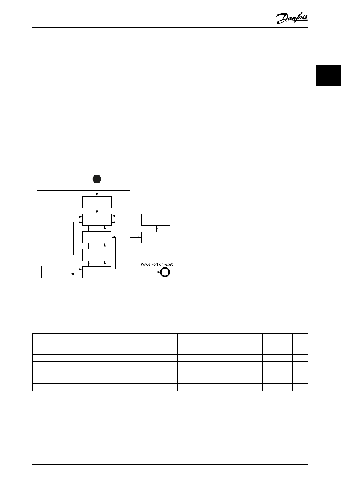
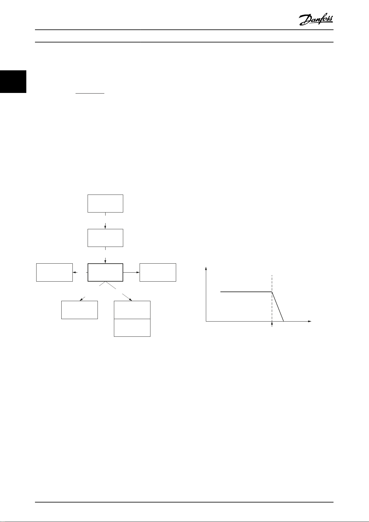
2.3.1 State Machine
The servo drive uses the state machine described in the CiA DS402 standard. The state machine is operated either locally via
the LCP or remotely via the network.
The state machine is operated by local signals and by the Controlword sent over the eldbus. The state of the state machine
is reported by the Statusword produced by the servo drive.
A single state represents a special internal or external behavior. The state of the state machine also determines which
commands are accepted.
Illustration 2.1 shows the state machine of the servo drive with regard to control of the power electronics as a result of
commands and internal servo drive faults.
2 2
Illustration 2.1 DS402 State Machine
The states support the functions shown in Table 2.1. The Start state is a pseudo state indicating the start when the state
machine is activated during the start-up sequence of the device drives application software.
Function
Brake applied, if present Yes Yes Yes Yes No No No Yes
Low-level power applied Yes Yes Yes Yes Yes Yes Yes Yes
High-level power applied Yes/no Yes/no Yes/no Yes Yes Yes Yes Yes/no
Drive function enabled No No No No Yes Yes Yes No
Conguration allowed Yes Yes Yes Yes Yes Yes Yes Yes
Table 2.1 DS402 States and Supported Functions
Quick stop active state is implemented, which is optional according to the standard. When entering this state, the behavior
of the servo drive is according to the option code
Option Code (0x605A)).
MG36D102 Danfoss A/S © 01/2017 All rights reserved. 19
Not ready to
switch on
Switch on
disabled
Ready to
switch on
Switched on
Operation
enabled
Quick stop
active
dened in object 0x605A (see chapter 7.20.6 Parameter 50-46: Quick Stop
Fault
reaction
active
Fault

Servo Drive Operation
VLT® Integrated Servo Drive ISD® 510 System
The transition from state Quick stop active to state Operation enabled (Transition 16 in Illustration 2.1) is not available, as
recommended by the standard.
22
The servo drive supports the transitions and actions as given in Table 2.2. The events initiate the transition. The transition is
terminated after the action has been performed.
High-level power applied means that UDC is applied at the input of the servo drive. Yes/No means that it is allowed but not
necessary.
Conguration allowed means that the following conguration is allowed:
Changes to the option code objects (see chapter 7.20 Option Code Objects).
•
Changes to the mode of operation object (see chapter 7.5.1 Parameter 52-00: Modes of Operation (0x6060)).
•
Transition Event Action
0 Automatic transition after power-on or reset
application.
1 Automatic transition. Communication is activated.
2 Shutdown command received from control device. –
3 Switch on command received from control device. High-level power is switched on, if possible.
4 Enable operation command received from control
device.
5 Disable operation command received from control
device.
6 Shutdown command received from control device. The congured shutdown reaction function is executed (see
7 Quick stop or disable voltage command received
from control device.
8 Shutdown command received from control device. The servo drive function is disabled and high-level power is switched
9 Disable voltage command received from control
device.
10 Disable voltage or quick stop command received
from control device.
11 Quick stop command received from control device. The quick stop function is started.
12 Automatic transition when:
Quick stop function is completed (see
•
chapter 7.20.6 Parameter 50-46: Quick Stop Option
Code (0x605A)).
Disable voltage command received from control
•
device.
13 Fault signal. The congured fault reaction function is executed (see
14 Automatic transition. The servo drive function is disabled and high-level power is switched
15 Fault reset command received from control device. If no fault exists on the servo drive, the fault condition is reset. After
16 Not supported. –
Servo drive self-test and self-initialization are performed.
The servo drive function is enabled and all internal setpoints are
cleared.
If the servo drive is rotating when the command to carry out transition
4 is received, the behavior is dened by option code
chapter 7.20.4 Parameter 50-44: Enable in Positioning Option Code
(0x2052).
The congured disable operation reaction function is executed (see
chapter 7.20.9 Parameter 50-49: Disable Operation Option Code (0x605C)).
chapter 7.20.8 Parameter 50-48: Shutdown Option Code (0x605B)).
–
o, if possible.
The servo drive function is disabled and high-level power is switched
o, if possible.
High-level power is switched o, if possible.
The congured quick stop reaction function is executed (see
chapter 7.20.6 Parameter 50-46: Quick Stop Option Code (0x605A)).
chapter 7.20.1 Parameter 50-41: Fault Reaction Option Code (0x605E)).
o, if possible.
leaving state Fault, clear the fault reset bit in the Controlword via
eldbus or the LCP.
Table 2.2 Transition Events and Actions
20 Danfoss A/S © 01/2017 All rights reserved. MG36D102

Position value =
position internal value x feed constant
position encoder resolution x gear ratio
Velocity value = x velocity factor
velocity internal value x feed constant
velocity encoder resolution x gear ratio
Velocity value = x velocity factor
position value
s
Servo Drive Operation Programming Guide
If a state transition is requested, the related actions are processed completely before transitioning to the new state. For
example, in state Operation enabled, when the disable operation command is received, the servo drive remains in state
Operation enabled until the disable operation function (see chapter 7.20.9 Parameter 50-49: Disable Operation Option Code
(0x605C)) is completed.
Drive function is disabled means that no energy is supplied to the motor. Target or setpoint values (for example, torque,
velocity, position) are not processed. Drive function is enabled means that energy is supplied to the motor. Target or setpoint
values are processed.
If a fault is detected in the servo drive, a transition to state Fault reaction active takes place. In this state, the state machine
executes a special fault reaction (see chapter 7.20.1 Parameter 50-41: Fault Reaction Option Code (0x605E)). After the execution
of this fault reaction, the servo drive automatically switches to state Fault. This state can only be left by using the fault reset
command, but only if the fault is no longer active.
2 2
If a fatal error occurs, the servo drive is no longer able to control the motor, so the servo drive must be switched
immediately. If a fatal error has occurred, the servo is trip-locked and cannot be reset via eldbus.
The behavior of drive disabling, quick stop, halt, and fault reaction functions are congurable via the objects dened in
chapter 7.20 Option Code Objects.
If a brake is present, the high-level power is switched o after a delay time in order to apply the brake.
2.3.2 Factor Group
Use the factor group to set the user-dened units required
in the application.
The user-dened units are:
Position units
•
Velocity units
•
Acceleration units
•
These units are used for all objects that support userdened units (for example, position actual value, prole
velocity, and prole acceleration).
Changing the objects in the factor group has an
immediate eect on all objects that support user-dened
units. Their numerical values stay the same, but they are
interpreted dierently (according to the new scaling factors
of the factor group). All numerical values are interpreted
using the current settings of the factor group.
Position units:
The position value is calculated as:
Position value means all objects containing values in user-
dened position units.
Position internal value is given in encoder increments.
Velocity units:
The velocity value is calculated as:
Velocity internal value is the position internal value(s),
resulting in the following formula:
o
NOTICE
If the factor group is changed, then the default values
are interpreted dierently.
The formulae in this chapter show the calculation of the
units. Objects, whose values are not dependent on the
factor group, have xed units specied with the objects.
The objects of the factor group can be found in
chapter 7.4 Factor Group Objects.
MG36D102 Danfoss A/S © 01/2017 All rights reserved. 21
Velocity value means all objects containing values in user-
dened velocity units.
Acceleration value = x acceleration factor
velocity value
s
Internal Encoder Position
(-)
TRC_ROTOR_POS_RAW
[increments]
Physical (Absolute) Position
(-)
TRC_ROTOR_POS
[increments]
Drive Position
(0x2022)
[user-dened position unit]
TRC_POS_ACT_REAL
[revolutions]
Position Actual Value
(0x6064)
TRC_POS_ACT_ABS
[user-dened position unit]
Logical CAM Position
(0x2020)
TRC_CAM_POS
[revolutions]
Only up to date if CAM
mode is active;
otherwise, the last value
remains
Position Actual Internal
Value
(0x6063)
[increments]
Encoder oset
(set during callibration)
Position oset
(set during homing)
Factor
group
Factor group +
Position range limit
(0x6078)
CAM osets
130BF158.10
Position
Hardware
limit switch
Velocity
Quick-stop
deceleration
130BF159.10
Servo Drive Operation
VLT® Integrated Servo Drive ISD® 510 System
Acceleration units:
The acceleration value is calculated as:
2.3.4 Position Limits
2.3.4.1 Hardware Limit Switch
22
One method to limit the positions of the servo drive is to
use limit switches (left/negative or right/positive), which
are also referred to as hardware limit switches. The limit
Acceleration value means all objects containing values in
user-dened acceleration units. The acceleration unit is also
used for deceleration.
2.3.3 Positions and Osets
Inside the servo drive, there are several logical positions.
Illustration 2.2 shows the relationships between them.
switches must be congured using object 0x200F (see
chapter 7.21.3 Parameter: Dual Analog User Inputs Conguration (0x200F)). When the servo drive reaches the Left
(Right) Limit switch, it ramps down to standstill using the
value set in object 0x6085 (see chapter 7.5.9 Parameter
50-13: Quick Stop Deceleration (0x6085)). It is possible to
command the servo drive out of the limit switch in the
opposite direction. The states of the limit switches are
indicated in object 0x2006 (see chapter 7.22.12 Parameter
50-08: Motion and Input Status (0x2006)).
The servo drive remains in state Operation enabled. If a
motion command is issued that would direct the servo
drive further in the wrong direction, the command is
rejected by setting the command error bit in the
Statusword. The monitoring of the limit switch is edgetriggered because the signal does not need to remain high
for the duration of the servo drive ramp-down time.
The hardware limit switch is monitored in all modes of
operation.
Illustration 2.2 Servo Drive Logical Positions
The object index is given in round brackets. The positions
oset is the oset that is calculated during a
without index numbers are not available in the object
dictionary but are used internally in the rmware of the
servo drive. The units are given in square brackets.
The Position
homing procedure (see chapter 2.4.4 Homing Mode). For
applications where the zero position only needs to be set
once during the lifetime of the servo drive, this oset can
be saved to non-volatile memory (see
chapter 7.7.8 Parameters 51-02, 52-04, and 52-49: Application
Settings (0x2016)).
22 Danfoss A/S © 01/2017 All rights reserved. MG36D102
Illustration 2.3 Hardware Limit Switch
2.3.4.2 Software Position Limit
The valid positions of the servo drive can also be limited
using software position limits (object 0x607D: Software
position limit). This object indicates the congured
maximum and minimum software position limits and is
used to monitor the position limits in all available modes
of operation.
Supervision of software position limits requires a dened
home position (the Is homed bit in the Statusword must be
set).
The behavior of the servo drive in a position-controlled
mode of operation diers to other modes. In a positioncontrolled mode of operation, the drive does not pass over
the software position limit. The target position is limited to
Position
Software
position limit
Velocity
Quick-stop
deceleration
Prole
deceleration
130BF160.10
Position
controlled
Velocity
controlled
Target
reached
Position
Command
Error
Positive software
limit active
Done
PLC
Fieldbus
Busy
Error
Positioning
command
Time
Software
position limit
Target
position
130BF161.10
Target
reached
Position
Command
Error
Positive software
limit active
Done
PLC
Fieldbus
Busy
Error
Positioning
command
Positioning only to
Software position limit
Time
Target
position
Software
position limit
130BF162.10
Target
reached
Position
Command
Error
Positive software
limit active
Done
PLC
Fieldbus
Busy
Error
Positioning
command
Software
position limit
Target
position
Time
130BF163.10
Servo Drive Operation Programming Guide
the software position limit. In all other modes of operation,
the servo drive immediately ramps down using the Quick
stop deceleration value (see chapter 7.5.9 Parameter 50-13:
Quick Stop Deceleration (0x6085)) when the software
position limit is passed. This means that the servo drive
always stops after the Software position limit.
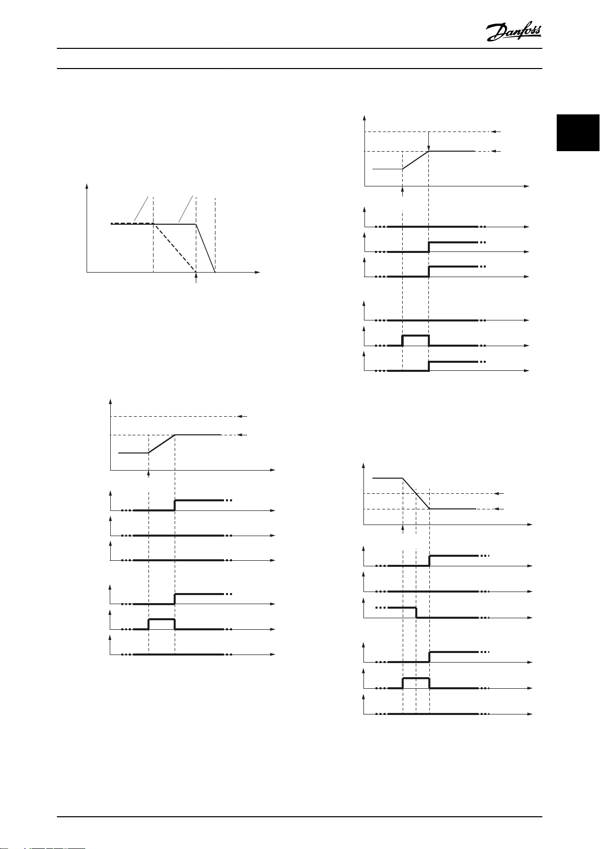
Illustration 2.4 Software Position Limit
Illustration 2.5 to Illustration 2.9 show the behavior of the
servo drive around the position limits.
2 2
Illustration 2.6 Position Command: Target Position is Behind
the Software Position Limit
Illustration 2.5 Normal Positioning: Target Position is in the
Valid Position Range
Illustration 2.7 Servo Drive is Outside the Valid Position Limit
and the Target Position is in a Valid Area
MG36D102 Danfoss A/S © 01/2017 All rights reserved. 23
Target
reached
Position
Command
Error
Positive software
limit active
Done
PLC
Fieldbus
Busy
Error
Positioning
command
Target
position
Software
position limit
Time
130BF164.10
Target
reached
Position
Command
Error
Positive software
limit active
Done
PLC
Fieldbus
Busy
Error
Time
Target
position
Software
position limit
Positioning
command
130BF165.10
Motor in
unpowered
state
Brake is open
Motor in
unpowered
state
Brake is closed
Motor is
energized
Brake is open
User command:
Close brake
Energize
motor
Unpower
motor
User command:
Open brake
Energize motor
130BF166.10
Servo Drive Operation
VLT® Integrated Servo Drive ISD® 510 System
2.3.5 Brake Handling
22
automatically lifts the brake. The servo drive reports the
new state after the brake is lifted.
When the servo drive leaves state Operation enabled, it
automatically releases the brake so that the axis cannot
sag down. The servo drive reports the new state after the
brake is unreleased.
The brake state can be overwritten using the digital output
object (see chapter 7.21.4 Parameter 16-66: Digital Outputs
(0x60FE)). This is only allowed in unpowered state. The
valid commands and the reactions are shown in
Illustration 2.10.
WARNING
UNINTENDED MOTION
Releasing the brake in an unpowered state may result in
unintended motion leading to death, serious injury,
damage to equipment, or other material damage.
Do not release the brake in an unpowered state.
When the servo drive enters state Operation enabled, it
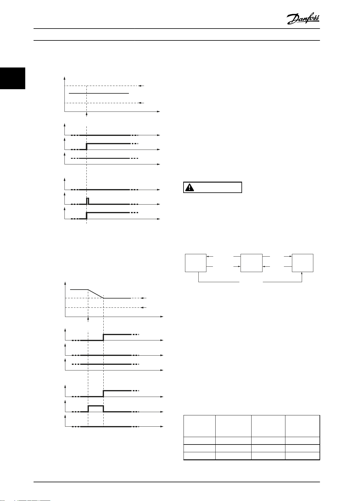
Illustration 2.8 Servo Drive is Outside the Valid Position Limit
and the Target Position is in the Wrong Direction
•
Illustration 2.10 Valid Brake Commands and Reactions
It is not possible to have an energized motor with a closed
brake. For further information about the current state, see
chapter 7.22.8 Parameter 50-09: STO Voltage and Brake Status
(0x2007).
2.3.6 Control Loops
Servo motor control takes place using 3 cascaded control
loops (position controller, speed controller, and current
controller) with trajectory generators for position and
velocity. The control loops run synchronously with the
eldbus cycles. The cycle times shown in Table 2.3 are
possible with Ethernet POWERLINK® and EtherCAT®:
Fieldbus cycle
[µs]
Illustration 2.9 Servo Drive is Outside the Valid Position Limit.
The Target Position is Still Not in a Valid Area, but is Nearer to
it than the Previous Position
24 Danfoss A/S © 01/2017 All rights reserved. MG36D102
400 200 200 100
500 250 250 125
800 200 200 100
Position control
cycle
[µs]
Speed control
cycle
[µs]
Current control
cycle
[µs]
Limit
function
Limit
function
Torque
control
Velocity
control
Position
control
Selector
Application torque limit (0x2053)
Max torque (0x6072)
Max motor speed (0x6080)
Feed forward torque
Feed forward velocity
Position demand
Internal value (0x60FC)
Controlword (0x6040)
Position controller parameters (0x2013)
Speed controller parameters (0x2012)
Position controller parameters 2 (0x2015)
Speed controller parameters 2 (0x2014)
+
+
+
+
– – –
+
P D
P D
Notch
Inertia
M
S
130BF167.10
I
Servo Drive Operation Programming Guide
Fieldbus cycle
[µs]
1000 250 250 125
Table 2.3 Ethernet POWERLINK® and EtherCAT® Cycle Times
Position control
cycle
[µs]
Speed control
cycle
[µs]
Current control
cycle
[µs]
Linear blending occurs from the parameter of the currently
active set to the new one. The blending time is dened in
object 0x201B (see chapter 7.6.2 Parameter 51-01: Control
Parameter Blending Time (0x201B)).
No blending takes place when writing to a value of the
currently active control parameter set. The new value is
The used cycle times can be read using object 0x201D (see
used immediately, which could cause a jerk on the shaft.
chapter 7.6.1 Parameter 51-07 to 51-09: Used Task Cycle
Times (0x201D)). The values are given in microseconds.
Blending is used when updating a whole set of parameters
at the same time (for example, when activating CAM mode,
There are 2 control parameter sets in the servo drive,
which uses its own sets of control parameters).
however only 1 of them can be active at any time. Use bit
15 (cs) in the Controlword to switch from 1 set to the other.
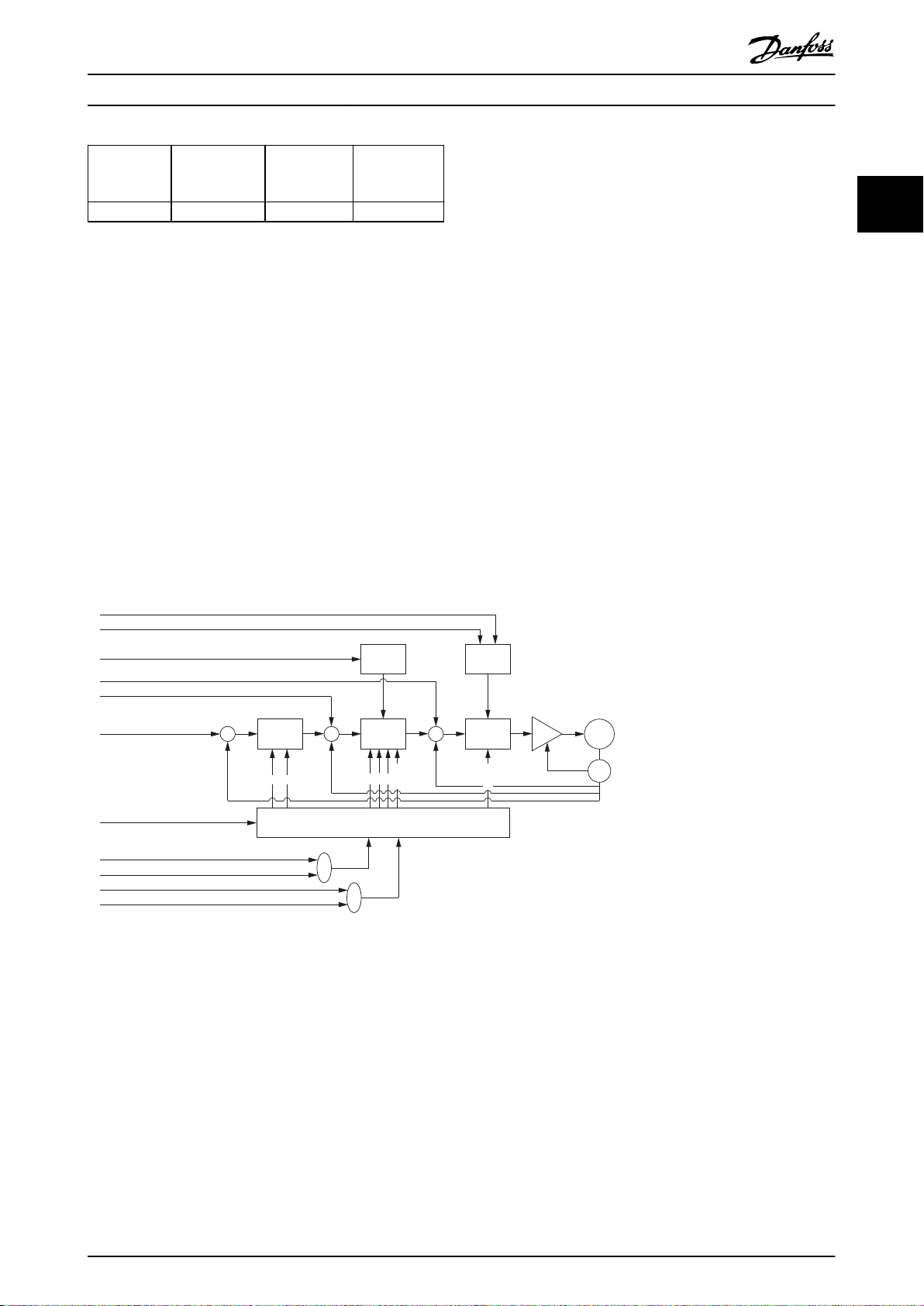
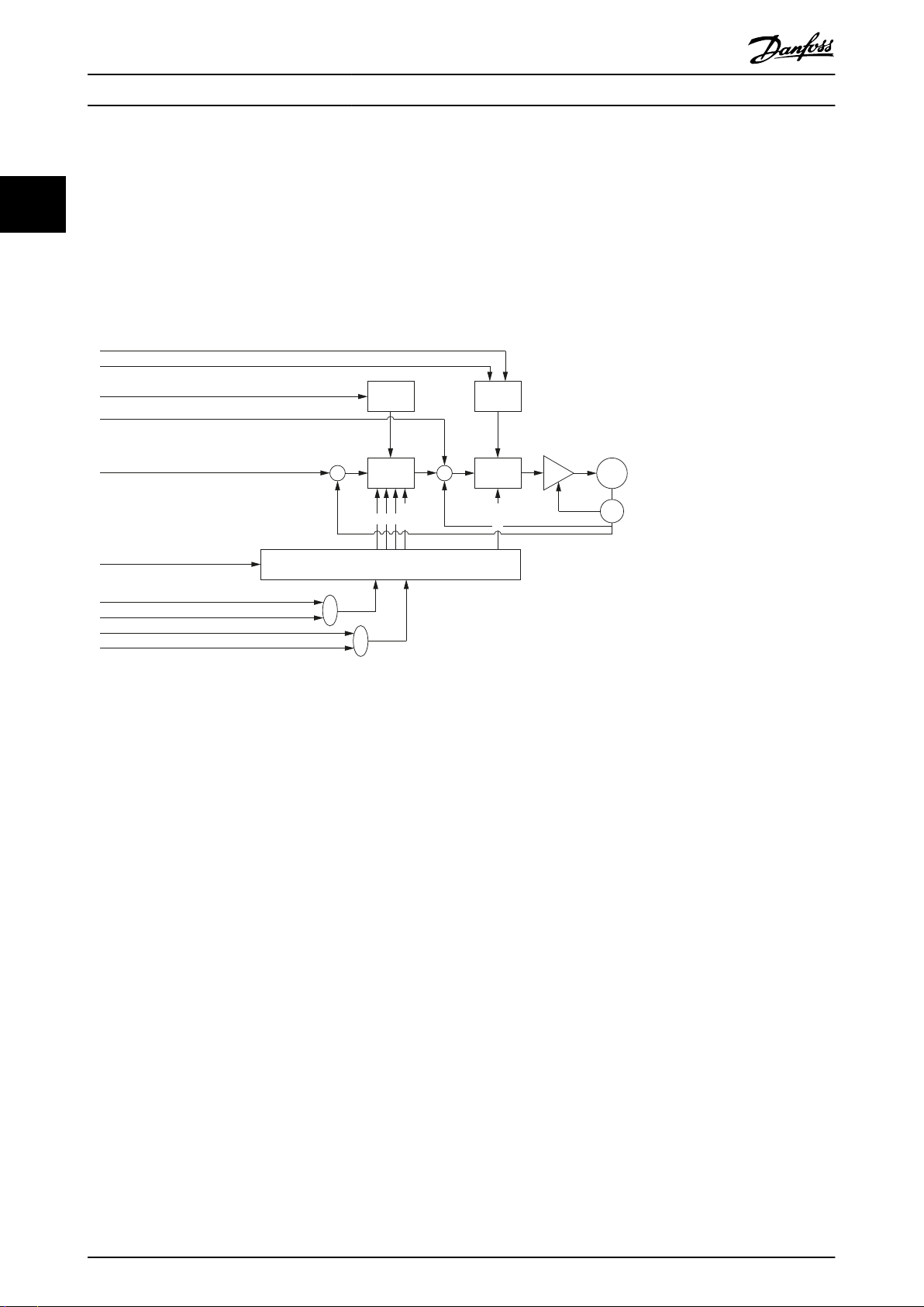
2.3.6.1 Position Controller
The controller uses PD control. The D constant is the derivative time constant. The controller provides 2 sets of control
parameters that can be switched during operation (see chapter 7.7.8 Parameters 51-02, 52-04, and 52-49: Application Settings
(0x2016) and chapter 7.6.4.2 Parameters 51-26 and 51-27: Position Controller Parameters 2 (0x2015)).
Both sets are available as read-write objects in the object dictionary. Use a manufacturer-specic bit in the Controlword to
switch between the 2 sets of parameters.
2 2
Illustration 2.11 Position Control Loop
MG36D102 Danfoss A/S © 01/2017 All rights reserved. 25
Limit
function
Limit
function
Torque
control
Velocity
control
Selector
Application torque limit (0x2053)
Max torque (0x6072)
Max motor speed (0x6080)
Feed forward torque
Feed forward velocity
Controlword (0x6040)
Position controller parameters (0x2013)
Speed controller parameters (0x2012)
Position controller parameters 2 (0x2015)
Speed controller parameters 2 (0x2014)
+ +
+
– –
P D
Notch
Inertia
M
S
130BF168.10
I
Servo Drive Operation
2.3.6.2 Speed Controller
VLT® Integrated Servo Drive ISD® 510 System
22
that can be parameterized (center frequency/bandwidth) to suppress resonance. The controller provides 2 sets of control
parameters (see chapter 7.6.5.1 Parameters 51-10 to 51-15: Speed Controller Parameters (0x2012) and chapter 7.6.5.2 Parameters
51-20 to 51-25: Speed Controller Parameters 2 (0x2014)) that can be switched spontaneously.
Both sets are available as read-write objects in the object dictionary. Use a manufacturer-specic bit in the Controlword to
switch between the 2 sets of parameters.
The controller uses PID control. The D constant is the derivative time constant. The speed controller has a Notch-Filter (IIR)
Illustration 2.12 Speed Control Loop
2.3.6.3 Current Controller
The current controller runs synchronous to the eldbus cycle time. It cannot be parameterized.
Operating Modes
2.4
The servo drive implements several modes of operation. The behavior of the servo drive depends on the activated mode of
operation. It is possible to switch between the modes while the servo drive is enabled. The supported modes of operation
are according to CANopen® CiA DS402 and there are also ISD-specic modes of operation. All supported modes of
operation are available for EtherCAT® and Ethernet POWERLINK®.
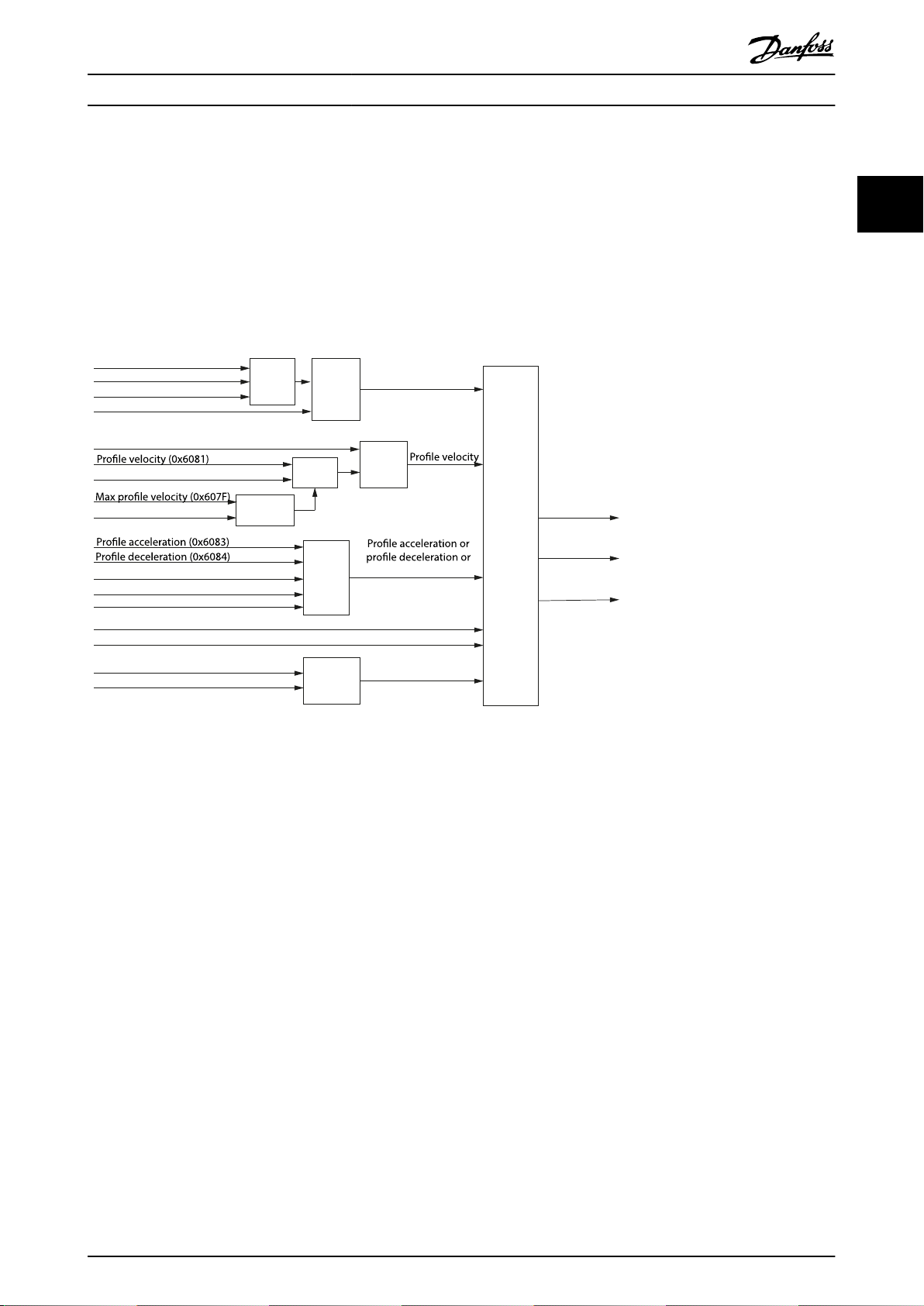
2.4.1 Prole Position Mode
In Prole position mode, the servo drive is operated under position control and executes absolute and relative movements.
Parameters such as velocity, acceleration, and deceleration can be parameterized. The servo drive provides a buer to queue
a following move while another move is already executing.
This functionality can be commanded using the function blocks MC_MoveAbsolute_ISD51x (see chapter 6.5.5.4 MC_MoveAb-
solute_ISD51x) and MC_MoveRelative_ISD51x (see chapter 6.5.5.5 MC_MoveRelative_ISD51x). This functionality can also be
used via the LCP (see section Position mode in chapter 4.3.5.1 Servo Drive).
When switching to Prole position mode from Prole velocity mode, CAM mode, Gear mode, or Prole torque mode, the servo
drive continues rotating with the current velocity. As soon as there is a new setpoint (handed over using the handshaking
between Controlword and Statusword), the new setpoint is processed with the corresponding parameters.
26 Danfoss A/S © 01/2017 All rights reserved. MG36D102
Tragectory
generator
Minimum
comparator
Minimum
comparator
Limit
function
Limit
function
Limit
function
Multiplier
Multiplier
Target position (0x607A)
Position range limit (0x607B)
Software position limit (0x607D)
Drive mirror mode (0x2016, 02)
Drive mirror mode (0x2016, 02)
End velocity (0x6082)
Max motor speed (0x6080)
Quick-stop deceleration (0x6085)
Max acceleration (0x60C5)
Quick-stop option code (0x605A)
Positioning option code (0x60F2)
Max torque (0x6072)
Application torque limit (0x2053)
Torque limit
Position demand
internal value
(0x60FC)
Feed forward
velocity
Feed forward
torque
Max deceleration (0x60C6)
quick-stop deceleration
Target position
Velocity limit
or End velocity
130BF169.10
Servo Drive Operation Programming Guide
When switching from a torque or velocity controlled mode to Prole position mode, the last target position is set to the
position actual value. This is relevant when starting a relative movement from the last target position after switching to this
mode, because no last target position from the previous mode is available. If the previous mode ended with a velocity
unequal to 0, the last target position is the position actual value at the time of the mode switch.
If the trajectory is completed (target position is reached) and the end velocity (see chapter 7.10.2 Parameter 52-16: End
Velocity (0x6082)) is unequal to 0, the servo drive continues rotating at the specied end velocity until a further trajectory is
set.
2 2
Illustration 2.13 Prole Position Mode Control Function
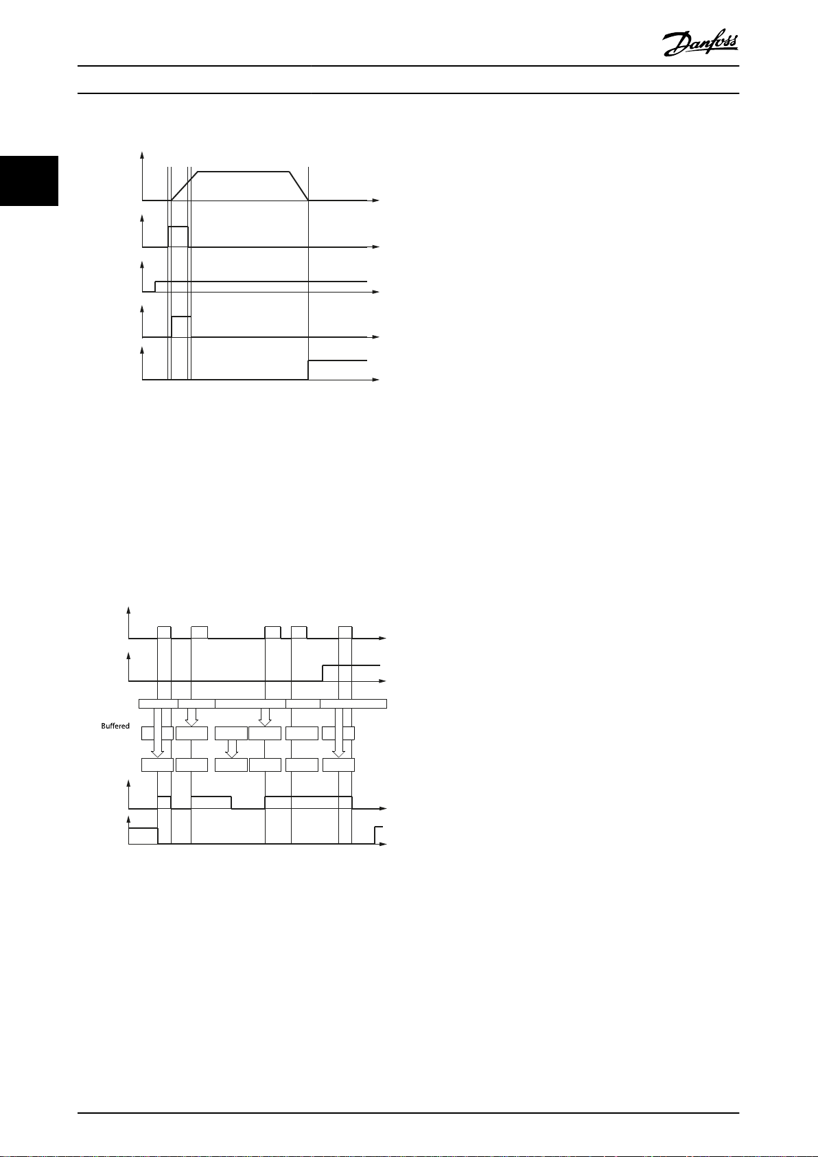
Target position activation
The activation of a setpoint is controlled by the timing of:
The new setpoint bit and the change set immediately bit in the Controlword.
•
The setpoint acknowledge bit in the Statusword.
•
If the Change set immediately bit of the Controlword is set to 1, a potentially ongoing motion is interrupted and the new
setpoint is used immediately. If the Change set immediately bit of the Controlword is set to 0, the ongoing positioning
command is nished rst and the new setpoint is executed afterwards.
After a setpoint is applied to the servo drive, the control device signals that the setpoint is valid by a rising edge of the new
setpoint bit in the Controlword. The servo drive sets the setpoint acknowledge bit in the Statusword to 1. Afterwards, the
servo drive with the setpoint acknowledge bit set to 0 signals its ability to accept new setpoints. An example is shown in
Illustration 2.14.
MG36D102 Danfoss A/S © 01/2017 All rights reserved. 27
Actual
speed
New
setpoint
(bit 4)
Target
position
(setpoint)
Setpoint
acknowledge
(bit 12)
Target
reached
(bit 10)
t
t
t
t
t
130BF170.10
A A B B B E
B
B C
C
C D
New
setpoint
(bit 4)
Change set
immediately
(bit 5)
Setpoint
ac
knowledge
(bit 12)
Target
reached
(bit 10)
Setpoint
setpoint
Processed
setpoint
1 2 3 4 5
t
t
t
t
130BF171.10
A
E
Servo Drive Operation
VLT® Integrated Servo Drive ISD® 510 System
22
Illustration 2.14 Handshaking Procedure for Setpoint
Activation
The servo drive supports 2 setpoints: a setpoint that is currently being processed, and a buered setpoint. If a setpoint is
still in progress (has not been reached) and a new setpoint is activated by the new setpoint bit in the Controlword, 2
methods of handling are supported. The new setpoint is activated immediately if the Change set immediately bit of the
Controlword is set to 1. If the Change set immediately bit of Controlword is set to 0, the currently active setpoint is nished
rst and the new setpoint is started afterwards.
Illustration 2.15 Setpoint Handling for 2 Setpoints
New setpoints are buered as long as a free setpoint buer is available in the axis. If no setpoint is in progress, the new
setpoint becomes active immediately (case 1 in Illustration 2.15). If a setpoint is in progress, the new setpoint is stored in the
setpoint buer (cases 2 and 3 in Illustration 2.15).
If all setpoint buers are busy (Setpoint acknowledge bit is set to 1), the reaction depends on the Change set immediately bit.
If the Change set immediately bit is set to 0, the new setpoint is rejected (case 4 in Illustration 2.15). If the Change set
immediately bit is set to 1, the new setpoint is processed immediately. The currently running setpoint prole is discarded
(case 5 in Illustration 2.15).
28 Danfoss A/S © 01/2017 All rights reserved. MG36D102

Actual
speed
New
setpoint
(bit 4)
Target
position
(setpoint)
Current target
position
processed
Setpoint
acknowledge
(bit 12)
Target
reached
(bit 10)
t
t
t
t
t
t
130BF172.10
Window
comparator
Limit
function
Comparator
Selector
Timer
Target reached option code (0x2054)
Position window time (0x6068)
Position window (0x6067)
Drive position (0x2022)
Position range (0x607B)
Target reached
Software position (0x607D)
Target position (0x607A)
Position demand value (0x6062)
Target position (0x607A)
–
130BF173.10
Servo Drive Operation Programming Guide
The Target reached bit in the Statusword remains as 0 until all setpoints are processed.
The Buered setpoint is not available as an object for readout.
When a setpoint is in progress and a new setpoint is set to start afterwards (New setpoint bit is set to 0), the new setpoint is
only processed after the previous setpoint has been reached. The handshaking procedure shown in Illustration 2.16 is used
for this scenario. The additional gray line in the graph Actual speed shows the actual speed if the Change of setpoint bit (bit
9 in the Controlword) is set to 1.
2 2
Illustration 2.16 Inuence of Change of Setpoint Bit in Prole
Position Mode
Position reached function
The position reached function oers the possibility to dene a range around a position demand value to be regarded as
valid. If the position of the servo drive is within this area for a specied time (the position window time), the related control
bit Target reached (bit 10) in the Statusword is set to 1.
Illustration 2.17 Position Reached – Functional Overview
MG36D102 Danfoss A/S © 01/2017 All rights reserved. 29
Accepted position range
Position
window
Position not
reached
Position not
reached
Position reached
Target
position
Position
Position
window
130BF174.10
Drive mirror mode (0x2016,02)
Target velocity (0x60FF) Limit
function
Limit
function
Trajectory
generator
d/dt
Minimum
comparator
Minimum
comparator
Multiplier
Max motor speed (0x6080)
Position actual value (0x6064)
Max torque (0x6072)
Torque limit
Feed forward
torque
Velocity demand
value (0x6068)
Velocity limit
quick-stop deceleration
Application torque limit (0x2053)
Max acceleration (0x60C5)
Max deceleration (0x60C6)
Quick-stop deceleration (0x6085)
Quick-stop option code (0x605A)
130BE847.10
Servo Drive Operation
VLT® Integrated Servo Drive ISD® 510 System
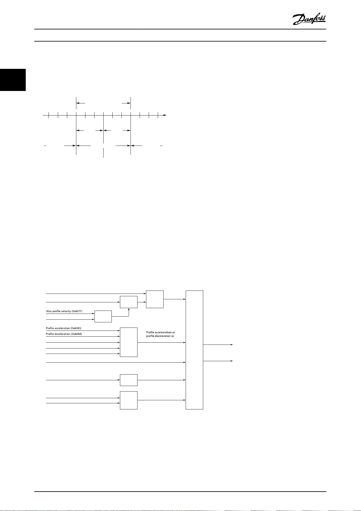
Illustration 2.18 shows the denition of the sub-function position reached. A window is dened for the accepted position
range symmetrically around the target position. If a servo drive is situated in the accepted position range over the time
position window time, the bit Target reached (bit 10) in the Statusword is set to 1.
22
Illustration 2.18 Position Reached Window
2.4.2 Prole Velocity Mode
In Prole velocity mode, the servo drive is operated under velocity control and executes a movement with a dened velocity
(see chapter 7.11.1 Parameter 52-20: Target Velocity (0x60FF)). Parameters such as acceleration (see chapter 7.5.7 Parameter
50-11: Prole Acceleration (0x6083)) and deceleration (see chapter 7.5.8 Parameter 50-12: Prole Deceleration (0x6084)) can be
parameterized. Parameters that inuence the Prole velocity mode can be found in Illustration 2.19.
This functionality can be commanded using function block MC_MoveVelocity_ISD51X (see chapter 6.5.5.7 MC_MoveVe-
locity_ISD51x). This functionality can also be used via the LCP (see the Velocity mode section in chapter 4.3.5.1 Servo Drive). In
Prole velocity mode, the velocity control loop is used to reach the target velocity (see chapter 7.11.1 Parameter 52-20: Target
Velocity (0x60FF)).
Illustration 2.19 Prole Velocity Mode Control Function
The usage of acceleration and deceleration for the calculation of the trajectory is shown in Illustration 2.20.
30 Danfoss A/S © 01/2017 All rights reserved. MG36D102

Target velocity
Velocity
acc
0
dec
acc dec acc dec
acc dec
130BE848.10
Target reached option code (0x2054)
Velocity window time (0x606E)
Velocity window (0x606D)
Velocity actual value (0x606C)
Velocity demand value (0x606B)
Target velocity (0x60FF)
Target velocity (0x60FF)
Target reached
Comparator
Window
comparator
Limit
function
Timer
Selector
130BE849.10
Servo Drive Operation Programming Guide
Illustration 2.20 Usage of Acceleration and Deceleration in
Velocity Control
This principle on using the acceleration and deceleration value applies to all velocity controlled modes of operation. The
ramp bends when reversing the velocity. If this behavior is undesired, set the value of the acceleration and deceleration to
the same value.
Velocity reached function
The velocity reached function oers the possibility to dene a velocity range around a velocity demand value to be
regarded as valid. If the velocity of the servo drive is within this area for a specied time (see chapter 7.11.4 Parameter:
Velocity Window (0x606D)), the velocity window time (see chapter 7.11.5 Parameter: Velocity Window Time (0x606E)), the
related control bit Target reached (bit 10) in the Statusword is set to 1.
2 2
Illustration 2.22 shows the denitions of the sub-function Velocity reached. A window is dened for the accepted velocity
range symmetrically around the velocity. If a servo drive is running within the accepted velocity range over the time velocity
window time, the bit Target reached (bit 10) in the Statusword is set to 1.
MG36D102 Danfoss A/S © 01/2017 All rights reserved. 31
Illustration 2.21 Velocity Reached - Functional Overview

Accepted velocity range
Velocity
window
Velocity not
reached
Velocity not
reached
Velocity reached
Target
velocity
Velocity
Velocity
window
130BE850.10
Trajectory
generator
Limit
function
Torque
control
and
power
stage
Target torque (0x6071)
Target slope (0x6087)
Max torque (0x6072)
Prole velocity (0x6081)
Torque demand (0x6074)
Velocity limit
Minimum
comparator
Max prole velocity (0x607F)
Max motor speed (0x6080)
Motor rated torque (0x6076)
Motor rated current (0x6075)
Torque actual value (0x6077)
Current actual value (0x6078)
130BF175.10
Servo Drive Operation
VLT® Integrated Servo Drive ISD® 510 System
22
Illustration 2.22 Velocity Reached Window
2.4.3 Prole Torque Mode
In Prole torque mode, the servo drive is operated under torque control and executes a movement with constant torque.
Linear ramps are used. Additional parameters, such as the torque ramp and maximum velocity can be parameterized. This
functionality can be commanded using function block MC_TorqueControl_ISD51X (see chapter 6.5.5.8 MC_Torque-
Control_ISD51x).
The
Prole torque mode allows transmitting the target torque value (see chapter 7.12.1 Parameter 52-30: Target Torque
(0x6071)), which is processed via the trajectory generator. The torque slope (see chapter 7.12.7 Parameter 52-32: Torque Slope
(0x6087)) is required. The servo drive supports linear ramps for calculation of the trajectory generation. If the Controlword bit
8 (Halt) is switched from 0 to 1, or from 1 to 0, then the trajectory generator ramps its control eort output down to 0, or
up to the target torque. In both cases, the trajectory generator uses the torque slope for the ramp calculation.
Illustration 2.23 Prole Torque Mode Control Function
Torque reached function
The Torque reached function oers the possibility to dene a torque range around a torque demand value to be regarded as
valid. If the torque of the servo drive is within this area (see chapter 7.12.8 Parameter: Torque Window (0x2050)) for a specied
time, the torque window time (see chapter 7.12.9 Parameter: Torque Window Time (0x2051)) and the related control bit 10
Target reached, in the Statusword is set to 1.
32 Danfoss A/S © 01/2017 All rights reserved. MG36D102
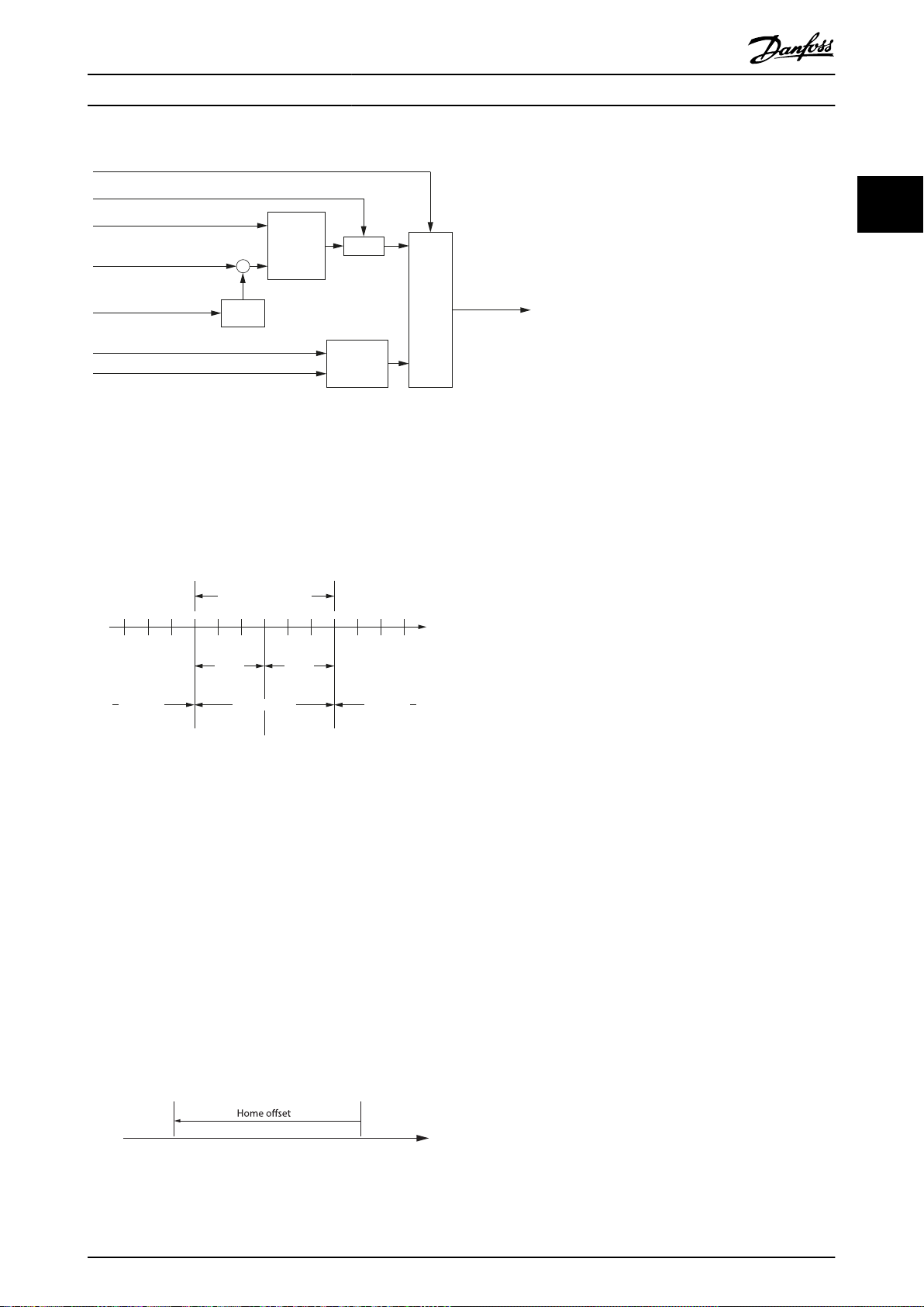
Target reached option code (0x2054)
Torque window time (0x2051)
Torque window (0x2050)
Torque actual value
Target reached
Target torque (0x6071)
Target demand (0x6074)
Target torque (0x6071)
Comparator
Selector
Timer
Window
comparator
Limit
function
130BF176.10
(0x6077)
Accepted torque range
Torque
window
Torque not
reached
Torque not
reached
Torque reached
Target
torque
Torque
Torque
window
130BF177.10
Zero
position
Home
position
130BF569.10
Servo Drive Operation Programming Guide
Illustration 2.24 Torque Reached - Functional Overview
Illustration 2.25 shows the denitions of the sub-function Torque reached. A window is dened for the accepted torque range
symmetrically around the velocity. If a servo drive is running within the accepted torque range over the time torque window
time, the bit target reached (bit 10) in the Statusword is set to 1.
2 2
Illustration 2.25 Torque Reached Window
2.4.4 Homing Mode
In Homing mode, the application reference position of the servo drive can be set. Several homing methods, described in this
chapter, are available.
This functionality can be commanded using MC_Home_ISD51x (see chapter 6.5.5.1 MC_Home_ISD51x).
The home position is the position where an event was triggered. The type of event depends on the homing method (for
example, detection of an edge of a switch). Based on this home position and the home
52-40: Home Oset (0x607C)), the new zero position is calculated (see Illustration 2.26).
Illustration 2.26 Home Oset Denition
MG36D102 Danfoss A/S © 01/2017 All rights reserved. 33
oset (see chapter 7.13.1 Parameter

Physical (Absolut) Position
Position Actual Internal
Value
(0x6063)
[increments]
(-)
TRC_ROTOR_POS
[increments]
Position oset =
permanent position oset + temporary position oset
(temporary position oset is set during homing)
130BF570.10
=>420°–360°=60°
Range limit: 0–360°
Home oset 420°
Home oset 180°
Current position
=home position (method 37)
60°
180°
360° 720°
720°360°
40°
360°0° 720°
0°
130BF178.10
Servo Drive Operation
VLT® Integrated Servo Drive ISD® 510 System
22
Illustration 2.27 Position Oset Denition
Illustration 2.28 Behavior of Homing with Software Range
Limit Applied
In Illustration 2.28, the lowermost solid line shows the current physical position of the servo drive. The software range limit is
applied so that the servo drive shows position actual values between 0° and 360°. The bold vertical line shows the current/
reference position, where the servo drive shows 40°. The ne dashed line in the middle shows the situation when activating
homing method 37 (Homing on current position) with a value for the home oset (0x607C) of 180°. The position actual value
(0x6064) shows 180°. The multi-turn revolutions are discarded. The bold dashed line at the top shows the situation when
activating homing method 37 (Homing on current position) with a value for the home oset (0x607C) of 420°. The position
actual value (0x6064) shows 60°. The multiples of the software range limit from the home oset are discarded.
The reference position found during homing is lost after a reset. However, it is possible to save this reference position
permanently (see sub-index 3 in chapter 7.7.8 Parameters 51-02, 52-04, and 52-49: Application Settings (0x2016) for details). The
homing bit is not set after a power-cycle, however the position is preserved.
34 Danfoss A/S © 01/2017 All rights reserved. MG36D102

Homing
method
Controlword (0x6040)
Drive mirror mode (0x2016.02)
Max torque (0x6072)
Homing method (0x6098)
Homing speeds (0x6099)
Statusword (0x6041)
Velocity demand value
(0x606B)
Homing acceleration (0x609A)
Homing deceleration (0x2040.04)
Homing oset (0x607C)
Homing blocking window velocity (0x2040.01)
Homing blocking window time (0x2040.02)
Homing limit distance (0x2040.03)
130BF179.10
Servo Drive Operation Programming Guide
Illustration 2.29 Homing Mode Function
The homing methods that require a physical input (home switch or limit switches) are available depending on the conguration of the analog inputs (see chapter 7.21.3 Parameter: Dual Analog User Inputs Conguration (0x200F)).
2 2
The methods are described in detail in the corresponding sub-chapters.
Value Denition
–3 Homing on actual position.
–2 Homing on positive block.
–1 Homing on negative block.
+17 Homing on negative limit switch.
+18 Homing on positive limit switch.
+19 Homing on positive home switch.
+21 Homing on negative home switch.
+37 Homing on current position.
Table 2.4 Supported Homing Methods
The successful completion of a homing procedure is indicated by bit 8 of the Statusword (home bit). This bit remains set
until the servo drive is power-cycled (U
), reset, or a new homing procedure is started.
AUX
Switching to Homing mode while the servo drive is in state Operation enabled is only allowed in standstill. In all other states,
the mode of operation can always be changed.
Exiting Homing mode (and switching to any other mode of operation) is allowed without restrictions. If homing procedure is
being carried out at that time, it is automatically aborted. In this case, the home bit in the Statusword is not set.
2.4.4.1 Homing on Actual Position
In method –3 Homing on actual position, the temporary part of the position oset is set to 0 (see Illustration 2.26). This
method does not require the servo drive to be in state Operation enabled, as there is no movement. If the servo drive is in
state Operation enabled during activation, it must be in standstill.
MG36D102 Danfoss A/S © 01/2017 All rights reserved. 35

MOVING
PAR T
130BF571.10
17
Negative Limit Switch
130BF180.10
18
Positive Limit Switch
130BF186.10
Servo Drive Operation
VLT® Integrated Servo Drive ISD® 510 System
2.4.4.2 Homing on Positive/Negative Block
22
Illustration 2.30 Example of Homing Method on Block
Method –1 Homing on negative block and method –2 Homing on positive block perform a homing against a physical object
that mechanically blocks the movement. A limit switch or home switch is not required.
NOTICE
An inadequate torque limit during the homing process
may result in damage to mechanics.
The servo drive is considered as blocked if the actual speed falls below the Homing blocking window velocity for the
specied Homing blocking window time (see chapter 7.13.6 Parameter 52-45 to 52-48: Additional Homing objects (0x2040)) and
the torque limit is reached (see chapter 7.5.12 Parameter: Maximum Torque (0x6072) and chapter 7.5.13 Parameters 52-15,
52-23, and 52-36: Application Torque Limit (0x2053)).
When the motor is blocked, the actual position is the home position. The motor then ramps down to 0 velocity using the
homing deceleration value and the successful homing procedure is reported.
The dierences between the 2 methods are:
Homing on negative block (–1): Motor moves with negative speed.
•
Homing on positive block (–2): Motor moves with positive speed.
•
2.4.4.3 Homing on Positive/Negative Limit Switch
Illustration 2.31 Homing Method 17: Homing on Negative
Limit Switch
Homing methods 17: Homing on negative limit switch or 18: Homing on positive limit switch can be used if a limit switch is
available (and congured using object 0x200F, see chapter 7.21.3 Parameter: Dual Analog User Inputs Conguration (0x200F)),
so that the limit switch signals the home reference point.
The dierences between the 2 methods are:
17: Homing on negative limit switch: Motor moves with negative speed to reach the negative limit switch.
•
18: Homing on positive limit switch: Motor moves with positive speed to reach the positive limit switch.
•
When starting the homing procedure, the servo drive starts moving with the dened velocity value set in object 0x6099
sub-index 01: Speed during search for switch (see chapter 7.13.3 Parameters 52-42 and 52-43: Homing Speeds (0x6099)). The
direction depends on the selected method (positive or negative). As soon as a rising edge is detected on the limit switch,
the motor reverses direction and ramps to the velocity set in object 0x6099 sub-index 2: Speed during search for zero (see
36 Danfoss A/S © 01/2017 All rights reserved. MG36D102
Illustration 2.32 Homing Method 18: Homing on Positive Limit
Switch

19
19
Home Switch
130BF181.10
Home Switch
21
21
130BF182.10
Servo Drive Operation Programming Guide
chapter 7.13.3 Parameters 52-42 and 52-43: Homing Speeds (0x6099)) until the switch is no longer active (falling edge). The
home position of the servo drive is at this edge. The motor ramps down to 0 velocity and the successful homing procedure
is reported. If the homing procedure is started and the limit switch is already set, the servo drive immediately signals a
homing error.
2.4.4.4 Homing on Positive/Negative Home Switch
Illustration 2.34 Homing Method 21: Homing on Negative
Illustration 2.33 Homing Method 19: Homing on Positive
Home Switch
Home Switch
2 2
Homing method 19 (positive) or 21 (negative) can be used if a home switch is available and can be congured using object
0x200F (see chapter 7.21.3 Parameter: Dual Analog User Inputs Conguration (0x200F)) so that the home switch signals the
home reference point.
The initial movement depends on the logical state of the home switch at activation. In all cases, the servo drive turns with
the velocity set in object 0x6099, sub-index 01: Speed during search for switch (see chapter 7.13.3 Parameters 52-42 and
52-43: Homing Speeds (0x6099)) until it encounters a signal change of the home switch. The servo drive reverses direction
and ramps to the velocity set in object 0x6099, sub-index 02: Speed during search for zero until the home switch changes
states again. The home position of the servo drive is at this edge. The motor ramps down to 0 velocity and the successful
homing procedure is reported.
The dierences between the 2 methods are:
Positive home switch (19): During activation of the homing procedure, a low state of the home switch leads to the
•
servo drive moving in a positive direction. A high state of the home switch leads to the servo drive moving in a
negative direction.
Negative home switch (21): During activation of the homing procedure, a low state of the home switch leads to
•
the servo drive moving in a negative direction. A high state of the home switch leads to the servo drive moving in
a positive direction.
2.4.4.5 Homing on Current Position
In this method (37), the current position of the servo drive is used as the home position. This method does not require the
servo drive to be in state Operation enabled because no movement occurs. If the servo drive is in state Operation enabled
during activation, it must be in standstill.
At the home position, the Position oset is calculated so that the value of the Position actual value (see
chapter 7.7.5 Parameter 50-03: Position Actual Value (0x6064)) equals the Home oset (see chapter 7.13.1 Parameter 52-40: Home
Oset (0x607C)):
Position actual value (0x6064) = Home oset (0x607C)
If the value of the Home oset is higher than the Position range limit, only the modulo part is used.
MG36D102 Danfoss A/S © 01/2017 All rights reserved. 37

Multiplier
Logical CAM
Position (0x2020)
Selector
Multiplier
Multiplier
Trajectory
generator
Drive Position (0x2022)
CAM slave scaling (0x3809)
CAM data 1-8 (0x3820 - 0x3827)
Minimum blending distance (0x380A)
Position guide value (0x2060)
Guide value scaling factor (0x3808)
Guide value oset (0x3806)
Velocity guide value (0x2064)
Guide value scaling factor (0x3808)
+
+
Position demand
internal value
(0x60FC)
(0x3805)
130BF183.10
Servo Drive Operation
VLT® Integrated Servo Drive ISD® 510 System
2.4.4.6 Error Behavior in Homing Mode
22
Homing objects (0x2040)) is used for supervising, the following error behavior applies:
If the limit is exceeded, the homing procedure is aborted. The servo drive signals a Homing error. If the servo drive is in
motion at this point of time, it ramps down with the quick stop deceleration (see chapter 7.5.9 Parameter 50-13: Quick Stop
Deceleration (0x6085)) to standstill but stays in state Operation enabled. Additionally, a warning is issued (Warning bit in
Statusword and setting of warning code).
The following situations can also lead to a warning:
For the methods where Homing limit distance (see sub-index 03: in chapter 7.13.6 Parameter 52-45 to 52-48: Additional
Entering Homing mode when not in standstill.
•
Starting a homing procedure while not in standstill. A warning and a homing error are reported. If the axis reaches
•
standstill, the homing method is started.
If the homing procedure reaches the homing distance, the homing is aborted and a warning is reported.
•
2.4.5 CAM Mode
In CAM mode, the servo drive executes a synchronized movement based on a master axis (guide value). The synchronization
takes place by means of a CAM prole that contains slave positions corresponding to master positions. CAMs are designed
with either the CAM Editor of the ISD Toolbox chapter 5.7.7 CAM Editor (Servo Drive only) or by using special structures in the
PLC library chapter 6.5.7 Drive – CAM Creation. The guide value can be provided by an external encoder, virtual axis, or the
position of another axis.
Illustration 2.35 Inputs for CAM Mode
When switching to CAM mode when the servo drive is not in standstill, it continues rotating with its current velocity. As
soon as a new CAM prole is activated, the new CAM prole is processed with the corresponding behavior. The servo drive
can hold a maximum of 8 CAM proles (see chapter 7.14.4 Parameters: CAM Prole 1–8 (0x3810–0x3817)). A CAM prole
consists of the CAM itself and its CAM conguration. CAM proles are automatically stored inside the servo drive.
There are 2 types of CAMs:
•
Basic CAM
A basic CAM is a list of data points that describe
the relationship between the slave position and
the master position. Each data point consists of:
- Master position
38 Danfoss A/S © 01/2017 All rights reserved. MG36D102
- Slave position
- Slave velocity
- Slave acceleration
Advanced CAM
An advanced CAM is represented by nodes,
segments, actions, and exit conditions. There are
•
dierent segment types that each have a special
functionality to provide intelligent application
functionality within the servo drive.

Servo Drive Operation Programming Guide
The CAM is represented in an XML le, which contains the
following information:
Master scaling (optional)
•
Slave scaling (optional)
•
Control loop parameter (optional; both sets)
•
Following error settings (optional)
•
Basic cam or advanced cam denition
•
The CAM conguration consists of the following
information:
Cyclic/non-cyclic
•
Master absolute/relative
•
Slave absolute/ relative (only applicable for basic
•
CAM)
For general information about the format of an XML le,
see chapter 10.2 General XML Conventions.
When parsing a CAM prole, the servo drive checks the
format and the plausibility. The result is available in the
sub-indexes 3 and 4 of the same objects (see
chapter 7.14.4 Parameters: CAM Prole 1–8 (0x3810–0x3817)).
These sub-indexes contain detailed information about the
parsing state, error result, and more detailed information
for debugging.
The factor group (see chapter 2.3.2 Factor Group) is not
used in CAM mode. The velocity must be given as a
unitless factor between rotor angle and angle of guide
value. The acceleration must be given as velocity per
degree of guide value. A CAM prole is running based on
the guide value. This value always runs from 0 to 1. To
adjust this to the real application environment, it is
possible to specify a factor (master scaling) to reduce or
increase the value that is considered as a full cycle.
There are 2 possible CAM buer layouts available:
8 CAM proles
•
2 CAM proles with more data
•
The CAM buer layout can be selected in object 0x380F
(see chapter 7.14.1 Parameter: CAM Prole Memory Layout
(0x380F)). Carry out a power-cycle to activate the selection.
All nodes are non-signaling nodes. The axis does not
automatically signal if it passes a node. However, for
example for debugging purpose, it is possible to enable
this signaling for selected nodes.
NOTICE
The factor group (feed constant, gear ratio, and so on)
has no eect in CAM mode.
Terminology
Name Description
CAM prole Consists of 1 CAM and 1 CAM
conguration. A valid CAM prole is
automatically stored in the servo
drive (maximum 8 CAM proles).
CAM XML le (basic CAM or advanced
CAM) containing the data points or
the nodes and segments.
CAM conguration Contains the following information:
- Cyclic/non-cyclic
- Master absolute/relative
- Slave absolute/relative
Basic CAM List of data points that describe the
relationship between the slave
position and the master position.
Advanced CAM Describes the relationship between
the slave and the master based on
nodes, segments, actions, and exit
conditions.
CAM prole activation
request (Handshaking)
Change CAM immediate/
delayed
CAM prole activation All setpoints of the CAM prole are
Full CAM A basic CAM that is dened with
Handshaking procedure with
Controlword and Statusword to
activate a valid CAM prole. This
does not necessarily mean that the
prole starts immediately. This
depends on the CAM conguration,
time of CAM activation request, and
so on.
In the Controlword there are 2
options for changing the CAM:
- Immediate: Abort the currently
running CAM and immediately
change to the new CAM.
- Delayed: The currently running
CAM prole nishes rst before
the CAM is activated (see
Illustration 2.37).
calculated and the servo drive is
able to run the CAM prole. This
mainly contains the calculations for
blending.
the 1st data point at guide value 0
and last data point at guide value
1. The CAM is dened over the
whole guide value cycle. Not
applicable for advanced CAM.
2 2
MG36D102 Danfoss A/S © 01/2017 All rights reserved. 39

New CAM
(Bit 4)
CAM
prole
selector
CAM ack
(Bit 12)
130BF184.10
Servo Drive Operation
VLT® Integrated Servo Drive ISD® 510 System
Name Description
Partial CAM
22
P5
End of prole Output signaling the end of the
InSync Output InSync is high as long as the
Blending Blending occurs whenever the servo
Table 2.5 Terminology
A CAM that is dened with the 1
data point not at guide value 0 or
last data point not at guide value 1
(or both). The CAM is only dened
on part of the guide value cycle.
Parts of the guide value are
“undened”. Not applicable for
advanced CAM.
Polynomial of 5th degree.
CAM prole. For cyclic processing of
the CAM, it is displayed every time
the end of the CAM prole is
reached. This signal is only high for
1 eldbus cycle. For basic CAMs, the
end of prole is signaled at the last
data point. For advanced CAMs, the
end of prole is signaled at each
end node.
slave follows the commanded CAM
prole.
drive automatically calculates a P5
when switching between CAMs, or
it is used to ll up the undened
parts in cyclic processing of CAMs.
st
To transfer a CAM prole, use function block MC_CamTable-
Select_ISD51x (see
chapter 6.5.6.1 MC_CamTableSelect_ISD51x).
CAM prole activation request (Handshaking)
The activation of a CAM prole is controlled by the timing
of the New CAM bit in the Controlword, and the CAM ack
bit in the Statusword. After a CAM prole is transferred and
successfully parsed, the control device signals that the
CAM prole will be activated (CAM prole activation
request) by a rising edge of the New CAM bit in the
Controlword. The axis internally calculates all necessary
parameters and afterwards sets the CAM ack bit in the
Statusword to 1. With the CAM ack bit set to 0, the axis
signals its ability to accept new CAM proles. An example
is shown in Illustration 2.36. After activation of the CAM
prole, the CAM is not necessarily executed immediately.
This depends on the CAM conguration and the change
immediate bit in the Controlword.
Illustration 2.36 Handshaking Procedure for CAM Prole
Activation
2.4.5.1 Activating a CAM prole
Perform the following steps to activate a CAM prole:
1. Write the CAM data to 1 of the objects 0x3820–
0x3827: CAM data 1–8 (see
chapter 7.14.5 Parameters: CAM Data 1–8 (0x3820–
3827)).
2. Write the CAM conguration and activate the
CAM parsing to the corresponding object
0x3810–0x3817: CAM prole, sub-index 01 (see
chapter 7.14.4 Parameters: CAM Prole 1–8
(0x3810–0x3817)).
3. Check the CAM parsing state in objects 0x3810–
0x3817: CAM prole, sub-index 02 and 03 (see
chapter 7.14.4 Parameters: CAM Prole 1–8
(0x3810–0x3817)).
4. Write the number of the CAM and the delay code
that should be used into object 0x3804: CAM
prole selector (see chapter 7.14.7 Parameter: CAM
Prole Selector (0x3804).
5. Switch to CAM mode (this can also be done
earlier).
6. Perform handshaking to send the CAM activation
request.
The CAM prole can also be activated using function block
MC_CamIn_ISD51x (see chapter 6.5.6.2 MC_CamIn_ISD51x).
The axis supports a set of 2 CAM proles numbers: a CAM
prole that is currently being processed, and a buered
prole.
If a CAM prole is still in progress and a new CAM prole
is validated by the new CAM (bit 4) in the Controlword, 2
methods of handling are supported:
The new CAM prole is activated immediately
•
(Change CAM immediately bit of the Controlword
is set to 1).
The currently active CAM prole is nished rst
•
and afterwards the new CAM prole is started
(Change CAM immediately bit of the Controlword
is set to 0).
When a new CAM prole is activated, all specic
parameters are activated at the start of the new prole
(this is the beginning of the blending). This can lead to
jumps in position and velocity, for example when using
dierent master scaling values.
40 Danfoss A/S © 01/2017 All rights reserved. MG36D102

New CAM
(Bit 4)
selector
status
CAM ack
(Bit 12)
Change CAM
immediately
(Bit 5)
1
2 3 4
5
A B C D E
A A
B
B B BCCE
130BF185.10
Servo Drive Operation Programming Guide
synchronization movement within the axis. This distance
should be regarded as a minimum value, as there are
situations where the servo drive automatically enlarges this
distance (for example, if the end of the distance does not
lead to a point of a dened CAM, see Illustration 2.50).
When using non-cyclic CAM proles, the inuence of
Master relative versus Master absolute is only an oset in
guide value direction. This is dependent on the point of
activation of the CAM prole.
2.4.5.3 CAM Header Information
2 2
Illustration 2.37 CAM Prole Handling for 2 CAM Proles
New CAM prole numbers are buered in the buered
CAM prole selector as long as there is a free CAM prole
selector buer available in the axis. If no CAM is in
progress, the new CAM prole becomes active immediately
(case 1 in Illustration 2.37).
If a CAM prole is in progress, the new CAM prole
number is stored in the CAM prole buer (cases 2 and 3
in Illustration 2.37). If all prole number buers are busy
(CAM ack bit is 1), the reaction depends on the Change
CAM immediately bit. If the Change CAM immediately bit is
set to 0, the new CAM prole is rejected (case 4) with a
command error indication (Statusword). If the Change CAM
immediately bit is set to 1, the new CAM prole number is
processed immediately. The currently running CAM prole
is discarded (case 5 in Illustration 2.37).
The Buered CAM prole selector is not available as an
object for readout. There are cases where it is necessary to
do a compensation movement when switching between
CAMs. This movement is called blending and it is
calculated automatically by the servo drive. The blending
takes place using a polynomial of 5th degree.
2.4.5.2 CAM Conguration: Master
Absolute/Relative
If the master and slave positions are congured to be
absolute positions, it is necessary to have a synchronization movement that aligns the position at the point of
activation with the set-position of the prole. This is called
blending. For blending, a polynomial of 5th degree is used.
It is automatically calculated by the servo drive.
The blending can be inuenced using bit Use blend
distance. When set to 0, the blending is done to the 1
data point of a basic CAM, or the start node of an
advanced CAM. This distance can be very short, which
leads to high velocity or acceleration.
When a concrete blend distance is used, set the Use blend
distance bit. Then, the value given in the minimum
blending object 0x380A (see chapter 7.14.11 Parameter:
Minimum Blending Distance (0x380A)) is used to calculate a
st
All parameters dened in this header information have
corresponding parameters in the object dictionary. These
objects are updated at the point of activation of the CAM.
If an element is not included in the header (which is
allowed for optional elements), the parameter in the object
dictionary remains unchanged. When leaving a CAM, the
values in the object dictionary persist; so they are not
switched back to their old values before the CAM
activation. The header information is the same for both
CAM types.
Illustration 2.38 CAM Header Information
Each le can only contain 1 CamProle element.
Mandatory/
Attri
optional
bute
(+default
value)
VersionO x.x.x.x Gives the version of the
Table 2.6 Attribute for Element CamProle
Value
range/
allowed
values
Description
CAM prole denition.
The CamProle element contains an optional element
masterScaling which denes the length of a guide value
cycle. This parameter is used as scaling factor. If this
element is missing, the values from the object dictionary
are used (see chapter 7.8.4 Parameter: Guide Value Scaling
Factor (0x3808)).
MG36D102 Danfoss A/S © 01/2017 All rights reserved. 41

Servo Drive Operation
VLT® Integrated Servo Drive ISD® 510 System
Mandatory/
Attribute
22
numerator M Same as for object
denominatorM Same as for object
Table 2.7 Attributes for Element masterScaling
optional
(+default
value)
Value range/
allowed values
0x3808, sub-index
1.
0x3808, sub-index
2.
Description
See object
0x3808, subindex 1.
See object
0x3808, subindex 2.
Attribute
speedP,
speedI,
speedD,
inertia
positionP,
positionD
Table 2.9 Attributes for Element controlParam1
The CamProle element contains an optional element
slaveScaling which denes the scaling factor for the axis. If
this element is missing, the values from the object
Attribute
dictionary are used (see chapter 7.14.10 Parameter: CAM
Slave Scaling (0x3809)). The same value range applies as
described for the objects in the object dictionary.
Mandatory/
Attribute
numerator M Same as for
denominatorM Same as for
optional
(+default value)
Value range/
allowed values
object 0x3809,
sub-index 1.
object 0x3809,
sub-index 2.
Description
See object
0x3809, subindex 1.
See object
0x3809, subindex 2.
speedP,
speedI,
speedD,
inertia
positionP,
positionD
Table 2.10 Attributes for Element controlParam2
The optional element followingError denes the following
error settings for the CAM. The mandatory attribute
windowRev refers to object 0x6065 (see
Mandatory/
optional
(+default
value)
M Float, same as for
M Float, same as for
Mandatory/
optional
(+default
value)
M Float, same as for
M Float, same as for
Value range/
allowed values
object 0x2012.
object 0x2013.
Value range/
allowed values
object 0x2014.
object 0x2015.
Description
See object
0x2012.
See object
0x2013.
Description
See object
0x2014.
See object
0x2015.
chapter 7.22.1.1 Parameter: Following Error Window (0x6065)),
Table 2.8 Attributes for Element slaveScaling
but the value must be given in revolutions. The mandatory
attribute time gives the time in milliseconds (see
Another optional element is the controlParam1, and/or
controlParam2 element, where the control loop parameters
chapter 7.22.1.2 Parameter: Following Error Time Out
(0x6066)). The following error behavior applies here.
are dened. Those 2 elements allow the automatic
overwriting of the 2 sets of control parameters (in the
object dictionary) on activation of the CAM. Both objects
are optional and can be present independently of each
other.
controlParam1 refers to the 1st set of control parameters
(see chapter 7.6.5.1 Parameters 51-10 to 51-15: Speed
Controller Parameters (0x2012) and
chapter 7.6.4.1 Parameters 51-16 and 51-17: Position
Controller Parameters (0x2013)), whereas controlParam2
refers to the 2nd set of control parameters (see
chapter 7.6.5.2 Parameters 51-20 to 51-25: Speed Controller
Parameters 2 (0x2014) and chapter 7.6.4.2 Parameters 51-26
and 51-27: Position Controller Parameters 2 (0x2015)).
Mandatory/
Attribute
windowRevM Float See object 0x6065 for
time M Same as
optional
(+default
value)
Value
range/
allowed
values
for object
0x6066.
Description
description, however this
value must be given in
revolutions. The servo
drive automatically
recalculates the value to
the value required for
object 0x6065.
See object 0x6066.
Table 2.11 Attributes for Element followingError
The rest of the CamProle element depends on the prole
type (basic or advanced) and is described in the following
chapters.
42 Danfoss A/S © 01/2017 All rights reserved. MG36D102

Guide value
Rotor angle of axis
0
1
130BF187.10
Servo Drive Operation Programming Guide
2.4.5.4 Basic CAM
Data points
The basic CAM consists of data points, which all have the same structure. There can be a maximum of 256 or 1024 data
points inside 1 basic CAM (see chapter 7.14.1 Parameter: CAM Prole Memory Layout (0x380F)).
Illustration 2.39 Basic CAM Data Points
Attribute
masterPos M Float: [0;1] Master position for this data point. Given in revolutions of
slavePos M Float Axis position for this data point. Given in revolutions of rotor
vel O;
acc O;
Mandatory/optional (+default
value)
default = 0
default = 0
Value range/allowed
values
Float Velocity of the axis in this data point. The velocity must be
Float Acceleration of the axis in this data point. The acceleration
Description
guide value. The masterPos inside a CAM prole is always
dened from 0 to 1.
position. SlavePos describes the position on the motor side.
given as a factor between the velocity of the axis in relation to
the velocity of the guide value (1 revolution of the axis per 1
round of guide value). Jumps in velocity are not possible.
must be given as a factor between the acceleration of the axis
in relation to the velocity of the guide value (1 revolution of
axis per square of round of guide value). Jumps in acceleration
are not possible.
2 2
Table 2.12 Attributes for a Data Point
All data points are non-signaling data points. The axis does
not automatically signal if it passes a data point. However,
it is possible to enable this signaling for selected data
points, for example for debugging purposes.
CAM conguration: Slave absolute/relative
When using the slave absolute option for a basic CAM, the
values of the slavePos attribute in the data point are used.
When using the slave relative option, the start of the CAM
is transferred to the current position of the slave.
CAM conguration: cyclic/non-cyclic
The dierent congurations are explained using
illustrations. There are 3 basic CAMs dened to show all
situations:
Illustration 2.40 shows a full CAM (1st data point
•
at masterPos 0, last data point at masterPos 1),
which has a velocity unequal to 0 in the 1st data
point.
Illustration 2.41 and Illustration 2.42 show partial
•
CAMs (1st data point not at masterPos 0, last data
point not at masterPos 1).
In the following chapters, several situations are dened.
The mentioned CAMs are used throughout the description
of the basic CAM to cover all situations.
Illustration 2.40 CAM 1 - Full CAM with Velocity of Last Node/
point = 0
MG36D102 Danfoss A/S © 01/2017 All rights reserved. 43

Rotor angle of axis
0 1
Guide value
130BF188.10
Guide value
Rotor angle of axis
0 1
130BF189.10
Rotor angle of axis
0 1 Guide value
cycle
2
Non-cyclic
CAM 1
Active
CAM
InSync
End of
0
130BF190.10
0 1 2
Non-cyclic
CAM 2
Active
CAM
InSync
End of
0
130BF191.10
Rotor angle of axis
Guide value
cycle
InSync
End of
prole
Rotor angle of axis
0 1
Guide value
cycle
2
Slave absolute
Cyclic
Blending
130BF192.10
Servo Drive Operation
VLT® Integrated Servo Drive ISD® 510 System
22
Illustration 2.41 CAM 2 - Partial CAM
Illustration 2.44 CAM 2: Partial CAM - Non-cyclic: Velocity at
the End is Unequal to 0
If the last data point of a CAM prole has a velocity other
than 0, and ends in this data point (for example, because
of non-cyclic conguration), the axis keeps on turning at
the velocity of this last data point (see Illustration 2.44).
Illustration 2.42 CAM 3 - Partial CAM
Non-cyclic CAM execution
However, the velocity is still related to the guide value. The
acceleration of this last data point is automatically set to 0.
Cyclic CAM execution
Illustration 2.43 CAM 1: Full CAM - Non-cyclic: Velocity at the
End is 0
44 Danfoss A/S © 01/2017 All rights reserved. MG36D102
Illustration 2.45 CAM 2: Partial CAM - Cyclic: Blending
Segment is an Automatically Calculated P5

InSync
End of
prole
Rotor angle of axis
0 1
Guide value
cycle
2
Slave relative
Cyclic
Blending
130BF193.10
Slave
relative
Rotor angle of axis
0 1
Guide value
cycle
2
Slave relative
Cyclic
Slave
relative
InSync
End of
prole
Jump in velocity!
130BF194.10
Rotor angle of axis
0 1
Guide value
cycle
2
Slave absolute
Cyclic
InSync
End of
Jump in position
and velocity!
130BF195.10
Servo Drive Operation Programming Guide
2 2
Illustration 2.46 CAM 2: Partial CAM - Cyclic, Slave relative:
Blending Segment is an Automatically Calculated P5.
The CAM is adjusted in a way that the 1st rotor angle value
matches the rotor angle of the last node.
A special case in Illustration 2.46 is when the velocity of the
last point and the velocity of the 1st point are both 0. Then
the P5 is actually a P0.
For smooth movements with cyclic use of fully dened
CAM proles, the 1st and the last data point of the proles
must match each other. “Matching” means having the
same velocity value and, depending on the conguration,
also the slave position value (see Illustration 2.47 and
Illustration 2.48).
Illustration 2.47 Cyclic, Full CAM Prole Dened Over the
Whole Guide Value Cycle.
The velocity of the 1st and the last node are not equal. During
execution, a jump may occur.
MG36D102 Danfoss A/S © 01/2017 All rights reserved. 45
Illustration 2.48 Cyclic, Full CAM Prole.
The velocity and the position of 1st and last nodes do not
match.
Switching between CAM proles
Depending on the CAM conguration options Master
absolute/relative and Slave absolute/relative, there are
several methods to transition from 1 running CAM prole
to the next. All the possibilities are described in the
illustrations in this section. The examples all show the
starting point based on the time of the CAM activation
request, or when CAM ack (bit 12) is set by the axis (see
chapter 2.4.5.1 Activating a CAM prole).
All illustrations in the following sub-chapters show the
transition from currently running CAM 2 (see
Illustration 2.41) to a newly activated CAM 1 (see
Illustration 2.40) or CAM 3 (see Illustration 2.42). The CAM
itself is always the same, but the illustrations show the
behavior with dierent congurations and settings.
The following conventions are used for transitions between
proles:
The blending distance has no inuence on the
•
position of the CAM (for example, regarding the
automatically calculated relative oset).
If a CAM prole is aborted (Change CAM
•
imm = 1), the current slave position is considered
as end slave position.
When activating a non-cyclic CAM prole with
•
Use blend distance = 0, the processing takes place
in the same master cycle (as the CAM activation
request) or in the next one (depending on the
end point of the currently running CAM prole
and the start point of the new CAM prole). In
both cases, the prole is processed as 1 complete
cycle (starting with the next upcoming start
node).
When activating a non-cyclic CAM prole with
•
Use blend distance = 1, the processing of it (at
least the start point) takes place in the same
master cycle (as the CAM activation request),
otherwise a CAM error is issued.

Guide value
cycle
Rotor angle of axis
0 1 2
InSync
End of
prole
Active
CAM
CAM 2 CAM 3
Blending
Master absolute
Slave absolute
Change CAM imm=0
Use blend dist=0
130BF196.10
Guide value
cycle
Rotor angle of axis
0 1
2
InSync
End of
Active
CAM
CAM 2 CAM 3
Blending
Master absolute
Slave absolute
Cyclic
Change CAM imm=0
Use blend dist=1
130BF197.10
blend
dist
Guide value
cycle
Rotor angle of axis
0
1
2
InSync
End of
Active
CAM
CAM 2 CAM 3
Blending
Master absolute
Slave absolute
Cyclic
Change CAM imm=0
Use blend dist=1
130BF198.10
blend
dist
0 1
130BF265.10
Rotor angle of axis
Master absolute
Slave absolute
Non-Cyclic
Change CAM imm=0
Use blend dist=1
InSync
End of
Prole
CAM
Error
Guide value
cycle
blend
dist
CAM 2
Active
CAM
Servo Drive Operation
VLT® Integrated Servo Drive ISD® 510 System
Absolute master position, absolute slave position
22
Illustration 2.51 Change CAM immediately = 0.
Illustration 2.49 Change CAM immediately = 0.
Do not use blending distance
Use blending distance; Blending distance is long enough to
cover the gap to the next CAM.
Illustration 2.50 Change CAM immediately = 0.
Use blending distance; Blending distance is not long enough
to reach the next CAM.
In Illustration 2.50, the blending distance is not long
enough to reach the 1st data point of the next CAM. The
axis therefore automatically increases the blending up to
the 1st point of the next CAM.
46 Danfoss A/S © 01/2017 All rights reserved. MG36D102
Illustration 2.52 The end of the blend distance is not on the
new CAM in the same guide value cycle.
This situation leads to a rejection of the transition. The servo
drive acts as if the command has never been issued.

130BF266.10
Rotor angle of axis
0 1 2
Master absolute
Slave absolute
Blending
Change CAM Imm=1
Use blend dist=0
InSync
End of
Prole
Active
CAM
Guide value
cycle
CAM 2 CAM 3
130BF267.10
Rotor angle of axis
10
Master absolute
Slave absolute
Non-Cyclic
blend
dist
CAM
Error
Active
CAM
InSync
End of
prole
Change CAM imm=1
Use blend dist=1
Guide value
cycle
CAM 2
Rotor angle of axis
130BF269.10
Master absolute
Slave absolute
0 1
Active
CAM
InSync
End of
prole
Blending
blend
dist
Change CAM imm=1
Use blend dist=1
Guide value
cycle
CAM 2 CAM 3
130BF268.10
Rotor angle of axis
0 1 2
Master absolute
Slave absolute
Cyclic
Blending
blend
dist
Active
CAM
InSync
End of
prole
Change CAM imm=1
Use blend dist=1
Guide value
cycle
CAM 2 CAM 3
Rotor angle of axis
130BF270.10
Master absolute
Slave absolute
0 1
Blending
Active
CAM
InSync
End of
prole
blend
dist
Change CAM imm=1
Use blend dist=1
Guide value
cycle
CAM 2 CAM 3
Servo Drive Operation Programming Guide
Illustration 2.53 Change CAM immediately = 1.
No blending distance used. The blending is then done
automatically to the beginning of the new CAM. It does not
necessarily mean that this is in the next cycle (for example,
see Illustration 2.57).
2 2
Illustration 2.55 Change CAM immediately = 1.
Use blending distance; Blending is possible to the new CAM
prole in the same cycle.
Illustration 2.54 The end of the blend distance is not on the
new CAM in the same guide value cycle.
This situation leads to a reject of the transition. An error is
issued because the 1st CAM was aborted with Change CAM
imm = 1.
MG36D102 Danfoss A/S © 01/2017 All rights reserved. 47
Illustration 2.56 Change CAM immediately = 1.
Use blending distance; Blending distance ends after the new
CAM prole ends; Blending is then extended to the starting
point of the next cycle.
Illustration 2.57 Use blending distance; Blending distance is
not long enough to reach the next CAM.
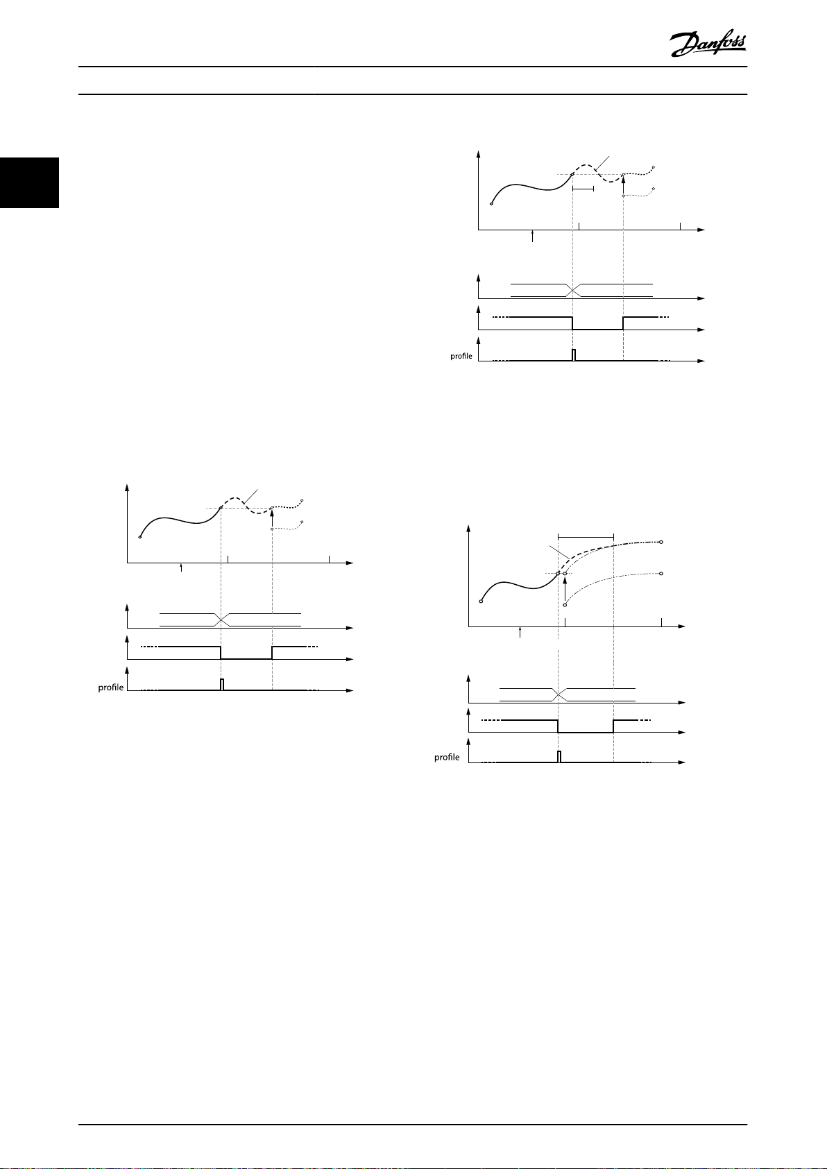
0 1 2
Active
CAM
InSync
End of
CAM 2 CAM 3
Slave
relative
Blending Master absolute
Slave relative
130BF272.10
Guide value
cycle
Rotor angle of axis
Change CAM imm=0
Use blend dist=0
0 1 2
Active
CAM
InSync
End of
CAM 2 CAM 3
Slave
relative
Blending
Master absolute
Slave relative
Cyclic
130BF271.10
Guide value
cycle
Rotor angle of axis
blend
dist
Change CAM imm=0
Use blend dist=1
0 1 2
130BF273.10
Guide value
cycle
Rotor angle of axis
CAM 2 CAM 1
Slave
relative
Master absolute
Slave relative
Cyclic
Blending
blend
dist
Active
CAM
InSync
End of
Change CAM imm=0
Use blend dist=1
Servo Drive Operation
VLT® Integrated Servo Drive ISD® 510 System
Absolute master position, relative slave position
Change CAM immediately = 0:
The currently running CAM is processed until the end. The
22
1st slave position of the new CAM is adjusted so that it
matches the slave position of the end point of the old
CAM prole.
Change CAM immediately = 1:
The currently running CAM is aborted immediately. The
slave position of the new CAM at the current guide value
is adjusted so that it matches the current slave position. If
the new CAM has not dened at this current guide value,
the slave value of the 1st point of the new CAM is adjusted
so that it matches the current slave position.
The behavior when switching to non-cyclic CAM
proles is
the same as detailed in section Absolute master position,
absolute slave position in chapter 2.4.5.4 Basic CAM. Options
slave absolute and slave relative have no inuence in these
cases and are therefore not mentioned again in this
section.
Illustration 2.59 Change CAM immediately = 0.
Use blending distance; Blending distance is not long enough
to reach the next CAM.
Illustration 2.58 Transition with absolute master and relative
slave positioning;
No blending distance used.
48 Danfoss A/S © 01/2017 All rights reserved. MG36D102
Illustration 2.60 Change CAM immediately = 0.
Use blending distance; Blending distance is long enough to
cover the gap to the next CAM.
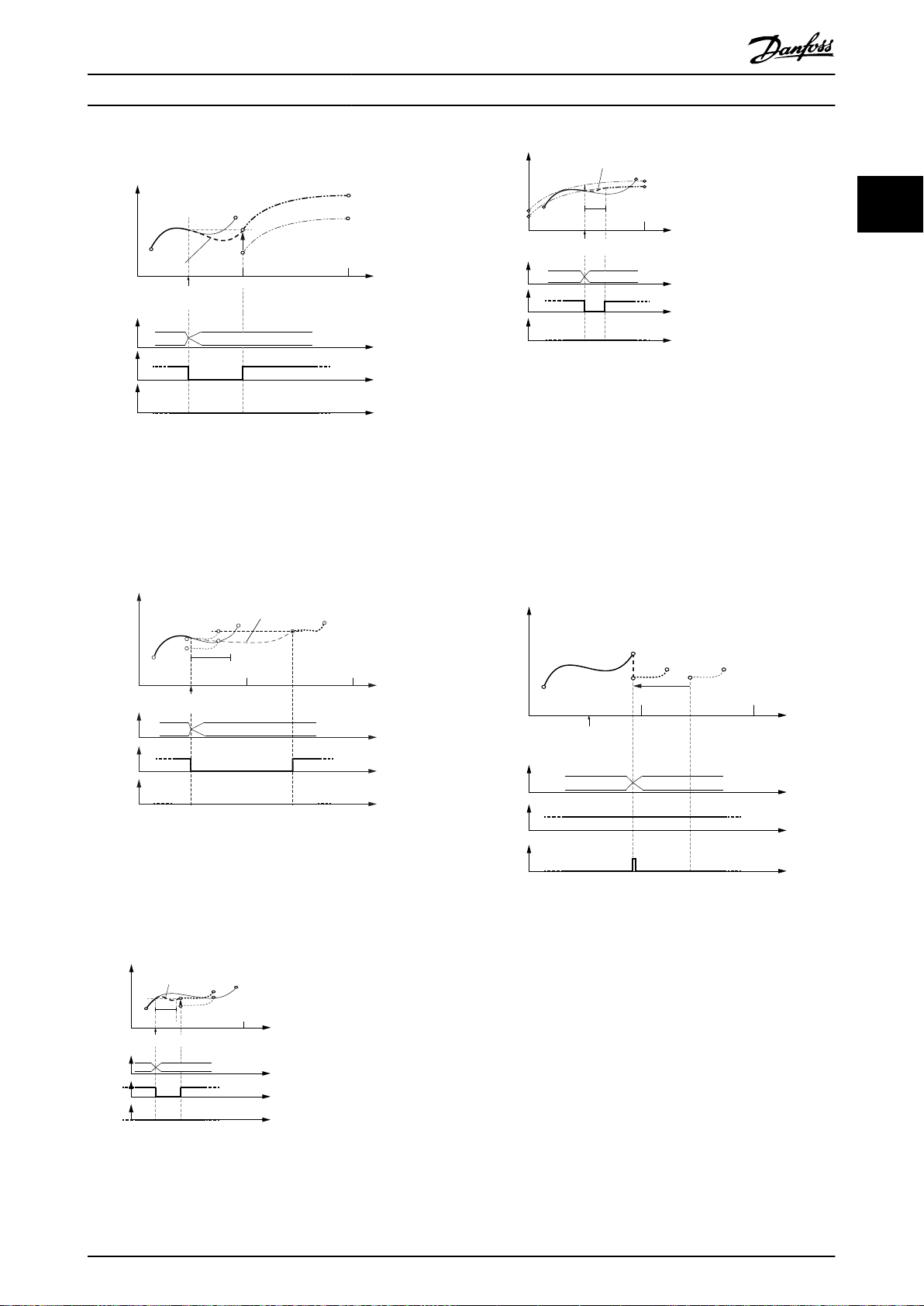
Active
CAM
InSync
End of
prole
0 1 2
130BF274.10
Guide value
cycle
Rotor angle of axis
CAM 2 CAM 1
Master absolute
Slave relative
Slave
relative
Blending
Change CAM imm=1
Use blend dist=0
Rotor angle of axis
Active
CAM
InSync
End of
prole
Change CAM imm=1
Use blend dist=1
CAM 2 CAM 3
Master absolute
Slave absolute
Cyclic
blend
dist
Blending
Slave
relative
Guide value
cycle
1 2
130BF572.10
0
1
130BF275.10
Guide value
cycle
Rotor angle of axis
Master absolute
Slave relative
Slave
relative
Blending
Active
CAM
InSync
End of
prole
blend
dist
Change CAM imm=1
Use blend dist=1
CAM 2 CAM 3
0 1
130BF276.10
Guide value
cycle
Rotor angle of axis
Master absolute
Slave relative
CAM 2 CAM 1
Slave
relative
Blending
Active
CAM
InSync
End of
prole
blend
dist
Change CAM imm=1
Use blend dist=1
Change CAM imm=0
Use blend dist=0
CAM 2 CAM 3
130BF277.10
Guide value
cycle
Rotor angle of axis
Active
CAM
InSync
End of
prole
Master relative
Slave absolute
0 1 2
Jump in position and
velocity possible!
Master
relative
Servo Drive Operation Programming Guide
2 2
Illustration 2.64 Change CAM immediately = 1.
Use blending distance; Blending is possible to the new prole
of the next CAM.
Illustration 2.61 Change CAM immediately = 1.
No blending distance used. The blending is then done
automatically to the beginning of the new CAM.
It does not necessarily mean that this is in the next cycle (for
example, see Illustration 2.62).
Illustration 2.62 Change CAM immediately = 1.
Use blending distance; Blending distance ends after the new
CAM prole ends;
Blending is then extended to the starting point of the next
cycle.
Relative master position, absolute slave position
In this case, the option Use blend distance is ignored. The
minimum blending distance (see chapter 7.14.11 Parameter:
Minimum Blending Distance (0x380A)) is used to calculate a
polynomial of 5th degree for the synchronization
movement to align the current rotor angle of the axis to
the slave position of the 1st data point in the CAM
Illustration 2.65 Change CAM immediately = 0.
Do not use blending distance. If the CAMs do not match in
slave position and velocity, a jump may occur.
This would probably lead to a following error.
prole.
Illustration 2.63 Change CAM immediately = 1.
Use blending distance; Blending distance is not long enough
to reach the next CAM.
MG36D102 Danfoss A/S © 01/2017 All rights reserved. 49

Change CAM imm=0
Use blend dist=1
CAM 2 CAM 3
130BF278.10
Guide value
cycle
Rotor angle of axis
Active
CAM
InSync
End of
prole
Master relative
Slave absolute
0 1 2
Master
relative
Blending
blend dist
Change CAM imm=0
Use blend dist=1
CAM 2 CAM 3
130BF279.10
Guide value
cycle
Rotor angle of axis
Active
CAM
InSync
End of
prole
Master relative
Slave absolute
Cyclic
0 1 2
Master
relative
Blending
blend dist
130BF280.10
Change CAM imm=0
Use blend dist=1
Master relative
Slave absolute
Non- cyclic
blend
dist
Guide value
cycle
Rotor angle of axis
0
1 2
Master
relative
Active
CAM
InSync
End of
prole
CAM
Error
CAM 2
130BF281.10
Guide value
cycle
Rotor angle of axis
0
1
2
Active
CAM
InSync
End of
prole
Master relative
Change CAM imm=1
Use blend dist=0
Master relative
Slave absolute
Jump in position and
velocity possible!
CAM 2 CAM 3
Servo Drive Operation
VLT® Integrated Servo Drive ISD® 510 System
22
Illustration 2.66 Change CAM immediately = 0.
Use blending distance; Blending distance is inside the new
CAM.
Illustration 2.68 The end of the blend distance is not on the
new CAM.
This situation leads to rejection of the transition. An error is
issued
because the 1st CAM was aborted with Change CAM
immediately = 1.
Illustration 2.67 Change CAM immediately = 0.
Use blending distance; Blending distance ends after the end
point of the new CAM.
50 Danfoss A/S © 01/2017 All rights reserved. MG36D102
Illustration 2.69 Change CAM immediately = 1.
No blending distance used. If the CAMs do not match in slave
position and velocity, a jump may occur.
This may lead to a following error.

130BF282.10
Guide value
cycle
Rotor angle of axis
0
1
2
Master relative
Slave absolute
Cyclic
Active
CAM
InSync
End of
prole
Change CAM imm=1
Use blend dist=1
Master
relative
blend
dist
Blending
CAM 2 CAM 3
130BF283.10
Guide value
cycle
Rotor angle of axis
0
1 2
Master relative
Slave absolute
Non- cyclic
blend
dist
Master
relative
Change CAM imm=1
Use blend dist=1
Active
CAM
InSync
End of
prole
CAM
Error
CAM 2
130BF284.10
Master relative
Slave absolute
blend distMaster
relative
Guide value
cycle
Rotor angle of axis
0
1
Change CAM imm=1
Use blend dist=1
Active
CAM
InSync
End of
prole
Blending
CAM 2 CAM 3
130BF285.10
Guide value
cycle
Rotor angle of axis
0
1
2
CAM 2 CAM 3
Active
CAM
InSync
End of
prole
Change CAM imm=0
Use blend dist=0
Master relative
Slave relative
Master relative
Jump in
velocity possible!
Slave
relative
Servo Drive Operation Programming Guide
Illustration 2.70 Change CAM immediately = 1.
Use blending distance; Blending distance ends after the end
point of the new CAM.
2 2
Illustration 2.72 Change CAM immediately = 1.
Use blending distance; Blending distance is shorter than the
new CAM prole.
Relative master position, relative slave position
The processing starts as soon as the CAM prole is
activated. The 1st point of the CAM prole is moved to the
current position and guide value. The behavior when
switching to non-cyclic CAM proles is the same as shown
in section Relative master position, absolute slave position in
chapter 2.4.5.4 Basic CAM. Option slave absolute or slave
relative has no inuence in these cases and is therefore not
mentioned again in this chapter.
Illustration 2.71 The end of the blend distance is not on the
new CAM.
The transition is rejected and the servo drive acts as if the
command was never issued.
Illustration 2.73 CAM prole with relative master and relative
slave positioning.
A jump in velocity may occur if the CAMs do not match.
MG36D102 Danfoss A/S © 01/2017 All rights reserved. 51

130BF286.10
Guide value
cycle
Rotor angle of axis
0
1
2
CAM 2 CAM 3
Active
CAM
InSync
End of
Change CAM imm=0
Use blend dist=1
Master relative
Slave relative
Master relative
Slave
relative
Blending
blend dist
130BF287.10
Guide value
cycle
Rotor angle of axis
0
1
2
Active
CAM
InSync
End of
prole
CAM 2 CAM 3
Change CAM imm=1
Use blend dist=1
Master relative
Slave relative
Cyclic
Slave
relative
Master
relative
Blending
blend
dist
130BF288.10
Guide value
cycle
Rotor angle of axis
0
1
2
CAM 2 CAM 3
Active
CAM
InSync
End of
prole
Change CAM imm=1
Use blend dist=0
Master relative
Jump in
velocity possible!
Slave
relative
Master relative
Slave relative
Servo Drive Operation
VLT® Integrated Servo Drive ISD® 510 System
22
Illustration 2.76 Change CAM immediately = 1.
Illustration 2.74 Change CAM immediately = 0.
Use blending distance.
Do not use blending distance. Jumps in velocity may occur.
2.4.5.5 Advanced CAM
Illustration 2.75 Change CAM immediately = 1.
Use blending distance; Distance is longer than the new CAM.
The advanced CAM is represented by nodes and segments.
The available node types are described in Table 2.13. The
available segment types are described in Table 2.14.
The CAM conguration options Slave absolute and Slave
relative are not available for advanced CAM. In advanced
CAM, the behavior of an absolute or relative movement is
built in to the dierent segment types.
A dierentiation between full and partial CAM is not
applicable for advanced CAM. An advanced CAM can
contain paths that form a circle, and alternative paths (see
Illustration 2.78), which end at nodes without further
following segment.
An advanced CAM prole can consist of several nodes,
segments, actions, and exit conditions. The size of a CAM
prole highly depends on the number of elements and, for
example, on the segment types (some require more and
others require fewer parameters).
Name Description
GuideNode Connects GuideSegments
EventNode Connects EventSegments
Table 2.13 Available Node Types
52 Danfoss A/S © 01/2017 All rights reserved. MG36D102
All nodes are non-signaling nodes. The axis does not
automatically signal if it passes a node. However, for
example for debugging purposes, it is possible to enable
this signaling for selected nodes.
GuidePoly GuideSegment
Polynomial of 5th order based on guide value.
MoveDistanceSegment
GuideSegment
Uses run-time calculated polynomial of 5
th
order; the angle is sent over eldbus at run-
time.

130BF289.10
Guide
value
nodeID3nodeID
0
nodeID1nodeID
2
segID 1
segID 2
segID 3
segID 4
segID 5
Rotor angle
of axis
130BF290.10
Guide
value
Rotor angle
of axis
nodeID3nodeID
0
nodeID1nodeID
2
segID 1
segID 2
segID 3
segID 4
segID 5
segID 6
segID 6
Servo Drive Operation Programming Guide
FlyingStopSegment
ReturnSegment GuideSegment
EventSegmentContainer
TimePoly EventSegment
VelocitySegment EventSegment
SyncSegment EventSegment
TorqueSegment EventSegment
PwmOSegment EventSegment
FrictionSegment EventSegment
Table 2.14 Available Segment Types
GuideSegment
Constant speed, followed by braking ramp,
angle of constant movement is sent over
eldbus at run-time.
Turns shaft to a symmetric angle (absolute
position) to eliminate rounding errors.
GuideSegment
All time-related movements must be
encapsulated by this segment type.
Polynomial of 5th order based on time.
Constant velocity, independent of the guide
value.
Constant velocity, depending on the guide
value.
Constant torque, independent of the guide
value.
Turns o the PWM.
Determines the friction of the system.
need to be the 1
st
node of the CAM (see Illustration 2.78).
The starting node must be a guide node.
End nodes dene the end of a non-cyclic CAM, or the end
when switching non-immediate to another CAM. Only
guide nodes can be end nodes. A guide node that has no
following segment is automatically dened as an end
node.
Illustration 2.78 NodeID 2 has no following segment:
It automatically becomes an end node.
An advanced CAM must have at least 1 end node, however
it is possible to have >1 end node within a CAM. If no end
node is explicitly dened, and there is no node without a
following segment (that implicitly would be an end node),
the start node becomes an end node.
2 2
This CAM
prole type can only be used with forward
turning guide values.
The advanced CAM prole consists of a list of nodes
(containing GuideNodes), a list of segments (containing
GuideSegments), an optional list of actions, and an optional
list of exit conditions.
Illustration 2.77 Advanced CAM Prole
Nodes
Nodes are dened by their position on the guide value.
The slave position is dened, where necessary, inside the
segments. The starting node of a CAM is the node with
nodeID 0. In a CAM, there must be exactly 1 starting node
(1 node with ID 0). However, this starting node does not
Illustration 2.79 No end node explicitly dened and no node
without following segment dened in the CAM.
NodeID 0 (start node) automatically becomes the end node.
A non-cyclic CAM ends at the 1st end point that is
processed. This can take several cycles of guide value or
continue innitely if there is no end node within the
currently processed path. For example, in Illustration 2.79,
when the path is set in a way that segID 1 is used instead
of segID 2, the start node is not in the active path.
A cyclic CAM just passes an end node like every normal
node; the End of Prole bit (see chapter 7.14.8 Parameter:
CAM Prole Status (0x3805)) is set. This bit is set for every
end node that is passed within a cyclic CAM. So, the end
of prole bit can also be set several times within 1 cycle. It
is also possible that it is not set at all if there is no end
node within the processed path.
MG36D102 Danfoss A/S © 01/2017 All rights reserved. 53

Servo Drive Operation
VLT® Integrated Servo Drive ISD® 510 System
A cyclic CAM that passes an end node without following
segment blends to the start node of the CAM prole. For
example, in Illustration 2.78, the nodeID 2 has no following
22
segment and when executing this CAM as cyclic CAM, the
axis blends from node ID 2 to node ID 0.
Attribute
signal O;
Non-immediate switching to another CAM takes place
when the currently running CAM passes the next occurring
end node (cyclic and non-cyclic). In Illustration 2.78, this
would be when passing node ID 2 and in Illustration 2.79,
this would be, when passing node ID 0. The switching only
takes place when node ID 0 is in the processed path.
Otherwise, a command is needed for segment ID 2 to be
endNode O;
the following segment of node ID 3.
GuideNode
GuideNodes are similar to data points within a machine
cycle. However, in contrast to data points of a basic CAM, a
GuideNode is only dened by its guide value position
(master position). The slave position, velocity, and
action O;
acceleration are not dened inside a GuideNode. This
information is given in the connected segments. The
velocity (and acceleration) of 2 segments that are
connected to the same node must match. Otherwise a
jump in velocity (and/or acceleration) occurs. Each node
has a unique ID for referencing to it. A GuideNode
combines GuideSegments so therefore, represents starting
and ending points of segments.
Illustration 2.80 XML Representation of a GuideNode
Mandatory/
optional
(+default
value)
default =
FALSE
default =
FALSE
default =
no action
Value range/
allowed values
FALSE or TRUE Denes if this node is
FALSE or TRUE Denes if this node is
0, 1, or more
existing action
IDs
Description
signaled by the axis.
This attribute is
optional. If it is not
present, the default
behavior is not to
signal this node.
an end node of the
CAM. This attribute is
optional. If it is not
present, the node is
no end node.
Denes if 1 or multiple
actions are attached to
this node. This
attribute is optional. If
it is not present, no
action is assigned to
this node. To dene
multiple actions for
this node, all action
IDs must be listed
inside the attribute,
separated by a white
space. If a non-existing
action ID is used, an
error is issued during
parsing.
Mandatory/
Attribute
nodeID M Integral
masterPos M Float; 0.0–1.0 Master position for this
optional
(+default
value)
Value range/
allowed values
number; 0–
65535
Description
Integral number to
uniquely identify this
node. The nodeID must
be unique across all
GuideNodes and
EventNodes. The same
nodeID cannot be used
twice. The node with
nodeID 0 is the
starting node.
GuideNode. Given in
revolutions of guide
value.
Table 2.15 Attributes for GuideNode
EventNode
Like GuideNodes, EventNodes are data points within a timerelated movement. They combine EventSegments in an
EventSegmentContainer. Each EventSegmentContainer has
exactly 1 rst EventNode, which has no preceding
EventSegment, and at least 1 ending EventNode, which has
no succeeding EventSegment.
Illustration 2.81 XML Representation of an EventNode
54 Danfoss A/S © 01/2017 All rights reserved. MG36D102

130BF289.10
Guide
value
nodeID3nodeID
0
nodeID1nodeID
2
segID 1
segID 2
segID 3
segID 4
segID 5
Rotor angle
of axis
Servo Drive Operation Programming Guide
Mandatory/
Attribute
nodeID M Integral
signal O;
action Same as in Table 2.15.
Table 2.16 Attributes for EventNode
optional
(+default
value)
default =
FALSE
Value
range/
allowed
values
number;
1–65535
FALSE or
TRUE
Description
Integral number to
uniquely identify this node.
The nodeID must be
unique across all
GuideNodes and
EventNodes. The same
nodeID cannot be used
twice.
Denes if this node is
signaled by the axis. This
attribute is optional. If it is
not present, the default
behavior is not to signal
this node.
Segments
There are 2 types of segment:
GuideSegments: All segment types that are
•
dened based on the guide value.
EventSegments: All segment types that are
•
dened based on time.
There are 2 types of XML representation for some of the
segments:
Start/Endpoint representation
•
Coecient representation
•
The availability of each type is stated in the corresponding
section.
All segments always have exactly 1 preceding and 1
succeeding node. Multiple segments can have the same
node as the preceding node. This is used to design
alternative paths. The selection between those paths takes
place during run-time (see chapter 2.4.5.6 Commands
During Operation).
In Illustration 2.82, an example is given where the segment
with ID 3 is an alternative to segment 4. Both have the
same preceding and succeeding nodes. It is also possible
to overleap a node, as shown in segment 1: it is an
alternative path to segments 2 and 3 or segments 2 and 4.
Multiple segments can also have the same node as the
succeeding node. The alternative paths are then combined
again and the further movement is common.
In Illustration 2.82, an example is given where segments
with ID 1, 3, and 4 all have the same succeeding node.
Regardless of which segment the servo drive is coming
from, segment 5 is processed afterwards.
Illustration 2.82 Example of Alternative Segments
GuideSegments
GuideSegments are all segment types that are
dened
based on the guide value. GuideSegments can only have
GuideNodes as preceding and succeeding nodes.
There are some attributes that are common to all
GuideSegments (see Table 2.17).
Mandatory/
Attribute
segID M Integral
precNode M An existing
succNode M An existing
optional
(+default
value)
Value
range/
allowed
values
number; 0–
50000
nodeID of a
GuideNode
nodeID of a
GuideNode
Description
Integral number to
uniquely identify this
segment. The segID must
be unique across all
GuideNodes and
EventSegments. The same
segID cannot be used
twice.
ID of the GuideNode at
the beginning of this
segment. If a non-existing
node ID is used, an error
is issued during parsing.
ID of the GuideNode at
the end of this segment.
If a non-existing node ID
is used, an error is issued
during parsing.
2 2
MG36D102 Danfoss A/S © 01/2017 All rights reserved. 55

130BF291.10
Guide
value
Rotor angle
of axis
distance
startPos
endVel
startVel
succNodeprecNode
Servo Drive Operation
VLT® Integrated Servo Drive ISD® 510 System
22
Mandatory/
Attribute
default O; default =
startAction O; default =
endAction O; default =
Table 2.17 Common Attributes for all GuideSegments
optional
(+default
value)
FALSE
no action
no action
Value
range/
allowed
values
TRUE/FALSE Denes if this segment is
0, 1, or
more
existing
action IDs
0, 1, or
more
existing
action IDs
Description
the default segment for
the referenced preceding
node.
This attribute is not
necessary if only 1
segment has this
precNode as preceding
node.
If >1 segment has this
precNode as preceding
node, and none of them
claims to be the default
one, the segment with
the lowest segment ID is
used.
If >1 segment claims to
be the default segment of
a specied precNode, a
parsing error is issued.
Denes if 1 or multiple
actions are attached to
the beginning of this
segment. This attribute is
optional. If it is not
present, no action is
assigned to the beginning
of this segment. To dene
multiple actions, all
actionIDs must be listed
inside the attribute,
separated by a white
space. If a non-existing
action ID is used, an error
is issued during parsing.
Denes if 1 or multiple
actions are attached to
the end of this segment.
This attribute is optional.
If it is not present, no
action is assigned to the
end of this segment. To
dene multiple actions, all
actionIDs must be listed
inside the attribute,
separated by a white
space. If a non-existing
action ID is used, an error
is issued during parsing.
GuidePoly:
The GuidePoly denes a movement that relates the rotor
angle of the axis with the guide value. Position, velocity,
and acceleration at the preceding and the succeeding
node can be selected without restrictions. It is therefore
possible to realize many movements already with a single
GuidePoly.
Complex movements can be combined by a number of
GuidePolys. When combining GuidePolys, the end velocity
of the segment and the start velocity of the next segment
must match, otherwise a jump in velocity occurs. It is
possible to dene absolute and relative movements.
Illustration 2.83 GuidePoly
Illustration 2.84 Start/Endpoint Representation
Mandatory/
Attribute
segID Same as in Table 2.17.
precNode Same as in Table 2.17.
succNode Same as in Table 2.17.
type M Absolute/
optional
(+default
value)
Value
range/
allowed
values
relative
Description
Denes if the segment is
executed at an absolute
slave position or if the
segment is executed
relative to the previous
position.
56 Danfoss A/S © 01/2017 All rights reserved. MG36D102
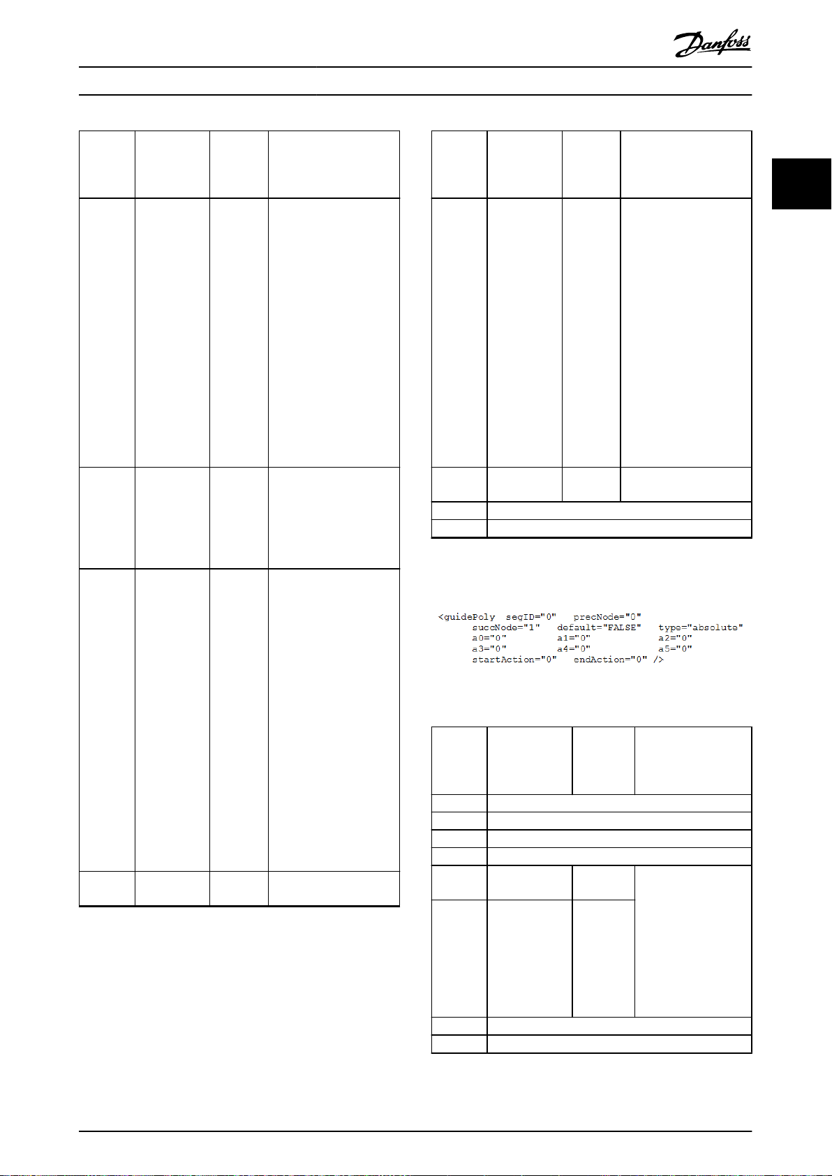
Servo Drive Operation Programming Guide
Mandatory/
Attribute
startPos M for type=
distance M Float Rotor angle of the axis
startVel O; default = 0 Float Velocity of the axis at the
endVel O; default = 0 Float Same as startVel but at
optional
(+default
value)
absolute;
O for type=
relative
Value
range/
allowed
values
Float Axis position at the
Description
beginning of this
segment. Given in
revolutions of rotor
position. startPos
describes the position on
the motor side. If it is a
relative segment, the
startPos attribute only
modies the Logical CAM
position. If startPos is not
present (in a relative
segment), the Logical
CAM position from the
previous segment is used
as startPos.
during this segment.
Given in revolutions of
rotor position. Use
negative values for
backward movements.
beginning of this
segment. The velocity
must be given as a factor
between the velocity of
the axis in relation to the
velocity of the guide
value (1 revolution of the
axis per 1 round of guide
value). To ensure smooth
movements, the velocities
of all segments that are
connected in the same
node should be the
same.
If not parameterized
correctly, a jump in
velocity may occur.
the end of the segment.
Mandatory/
Attribute
startAcc O; default = 0 Float Acceleration of the axis at
endAcc O; default = 0 Float Same as startAcc but at
startAction Same as in Table 2.17.
endAction Same as in Table 2.17.
Table 2.18 Attributes for GuidePoly in Start/Endpoint
Representation
Illustration 2.85
Attribute
segID Same as in Table 2.17.
precNode Same as in Table 2.17.
succNode Same as in Table 2.17.
type Same as in Table 2.17.
a0 type = absolute:
a1-a5 M Float
startAction Same as in Table 2.17.
endAction Same as in Table 2.17.
optional
(+default
value)
Coecient Representation
Mandatory/
optional
(+default value)
M else O
Value
range/
allowed
values
Value
range/
allowed
values
Float Polynomial coecients
Description
the beginning of this
segment. The
acceleration must be
given as a factor between
the acceleration of the
axis in relation to the
velocity of the guide
value (1 revolution of axis
per square of round of
guide value).
Jumps in acceleration
may occur when 2
succeeding segments
have dierent startAcc
and endAcc values.
the end of the segment.
Description
for the movement
described by a5x5 +
a4x4 + a3x³ + a2x² +
a1x + a0
a0 is the same as
startPos in the Start/
Endpoint representation.
2 2
Table 2.19 Attributes for GuidePoly in Coecient Representation
MG36D102 Danfoss A/S © 01/2017 All rights reserved. 57

130BF293.10
Guide
value
Rotor angle
of axis
startPos
endVel
startVel
succNode
precNode
Distance is variable;
needs to be sent at
run-time in every
machine cycle
Guide
value
Rotor angle
of axis
startPos
succNodeprecNode
maxConstDist
startVel
brakeLength
brakeDist
Distance is variable;
needs to be sent at
run-time in every
machine cycle
130BF294.10
Servo Drive Operation
VLT® Integrated Servo Drive ISD® 510 System
MoveDistanceSegment:
MoveDistanceSegments are used for movements with no
22
predened rotation angle. The desired rotor angle is given
to the axis during run-time. It must be given before the
beginning of the segment. It must be given in every
machine cycle (see Table 2.53 in chapter 2.4.5.6 Commands
During Operation).
This segment is mostly used together with an external
camera for object alignment. The start and end velocity,
Attribute
startAcc Same as in Table 2.18.
endAcc Same as in Table 2.18.
startAction Same as in Table 2.17.
endAction Same as in Table 2.17.
Table 2.20 Attributes for MoveDistanceSegment in
Start/Endpoint Representation
Mandatory/
optional
(+default value)
Value range/
allowed
values
Description
and the start and end acceleration can be parameterized.
The parameter that is sent during run-time must be given
in revolutions of rotor angle. The rotor angle must be sent
at least 5 ms before the segment begins.
If no parameter is sent for this segment, the axis reports an
error (see chapter 2.4.5.7 Notications from the Servo Drive)
and assumes a distance of 0. An error message is sent
when passing the precNode of this segment. A new
parameter message, meant for the next cycle, can be sent
to the servo drive when the succNode of this segment has
been passed.
Coecient representation: This representation is not
available.
FlyingStopSegment:
The FlyingStopSegment is used to stop the servo drive out
of a synchronous movement at a position, which can be
determined at run-time. This angle is usually determined
by a camera system. The motion consists of 2 parts, a
constant rotation, which length is dened by the sent
parameter, and a deceleration polynomial for stopping the
servo drive (a polynomial of 3rd degree is used). The angle
must be passed before the segment has started. The
parameter can be in a range from 0° to maxConstantDist.
The value is given as an absolute value. The direction is
determined by the direction of the velocity.
The rotor angle must be sent during run-time but before
the beginning of this segment. When the constant part has
been processed for the parameter, which was given, the
stopping part of the segment starts. This braking
polynomial is always the same, independent of the
remaining distance to the end of the segment.
The parameter that is sent during run-time must be given
in revolutions of rotor angle. The rotor angle must be sent
at least 5 ms before the segment begins. If no parameter is
Illustration 2.86 MoveDistanceSegment
sent for this segment, the axis reports an error (see section
Notications from the servo drive in this sub-chapter) and
assumes a distance of maxConstDist. The error message is
sent when passing the precNode of this segment. A new
parameter message, meant for the next cycle can be sent
to the servo drive when the succNode of this segment was
passed.
Illustration 2.87 Start/Endpoint Representation
Mandatory/
Attribute
segID Same as in Table 2.17.
precNode Same as in Table 2.17.
succNode Same as in Table 2.17.
startPos O Float See Table 2.18 for
startVel Same as in Table 2.18.
endVel Same as in Table 2.18.
58 Danfoss A/S © 01/2017 All rights reserved. MG36D102
optional
(+default value)
Value range/
allowed
values
Description
type= relative.
Illustration 2.88 FlyingStopSegment

Servo Drive Operation Programming Guide
Illustration 2.89 Start/Endpoint Representation
Illustration 2.90
2 2
Coecient Representation
Mandat
ory/
Attribute
segID Same as in Table 2.17.
precNode Same as in Table 2.17.
succNode Same as in Table 2.17.
startPos O Float See Table 2.18 for type=
startVel Same as in Table 2.18.
maxConstDist M Float>0Denes the maximum rotor
brakeDist M Float>0Rotor angle of the axis during
brakeLength M Float>0Guide value for the length of
startAction Same as in Table 2.17.
endAction Same as in Table 2.17.
optional
(+defaul
t value)
Value
range/
allowe
d
values
Description
relative.
angle that the axis turns if no
parameter is sent during runtime. Given in revolutions of
rotor position. Only positive
values are allowed. The value is
considered as absolute value in
the direction of the start
velocity.
the deceleration phase of this
segment. Given in revolutions
of rotor position. Only positive
values are allowed. The value is
considered as absolute value in
the direction of the start
velocity. There must be
enough space to be able to
brake also in worst case
situations.
the deceleration phase of this
segment. Given in revolutions
of guide value. The segment
must be long enough to run
the maxConstDist and have
enough guide value left for at
least the brakeLength. If there
is space left, the servo drive
remains in standstill until the
succeeding GuideNode is
reached.
Mandatory/
Attribute
segID Same as in Table 2.17.
precNode Same as in Table 2.17.
succNode Same as in Table 2.17.
a0 type =
maxConstDist Same as in Table 2.21.
brakeLength Same as in Table 2.21.
a1-a3 M Float Polynomial coecients
startAction Same as in Table 2.17.
endAction Same as in Table 2.17.
Table 2.22 Attributes for FlyingStopSegment in Coecient
Representation
optional
(+default
value)
absolute: M
else O
Value
range/
allowed
values
Float Polynomial coecients
Description
for the movement
described by a5x5 +
a4x4 + a3x³ + a2x² +
a1x + a0
a0 is the same as
startPos in the Start/
Endpoint representation.
for the movement
described by
a3x³ + a2x² + a1x
It is not necessary to
give a0 as this
information comes
from the position
value of the
beginning of the
decelerating part.
a1 is also the velocity
for the constant part
of the segment. This
value must be
unequal to 0. The
coecients must be
given so that the
braking part ends in a
standstill.
Table 2.21 Attributes for FlyingStopSegment in Start/Endpoint
Representation
ReturnSegment:
The ReturnSegment is used to return from any position to a
dened absolute position. In this way, all osets of the
logical rotor angle are discarded and a xed relation
MG36D102 Danfoss A/S © 01/2017 All rights reserved. 59

+ osetRev
partition
revolutions
Guide
value
Rotor angle
of axis
startPos
succNodeprecNode
130BF295.10
End position
depends on the
position at the start
of the segment and
the parameters
22
Servo Drive Operation
VLT® Integrated Servo Drive ISD® 510 System
between logical and absolute rotor angle is established or
re-established. This is useful, if the axis has to be moved to
an absolute position after a loss of the reference position
by using a variable movement (for example, MoveDistance-
Segment).
Usually the ReturnSegment is used at the beginning of the
CAM to start from a dened absolute position. The Return-
Illustration 2.92 Start/Endpoint Representation
Segment is used in conjunction with devices which have
multiple, equidistant, and equivalent starting positions, for
example, a square device.
The axis automatically selects the shortest way and
calculates a polynomial of 5th degree to reach the next
valid position. A backward movement of the servo drive is
possible. Valid positions are calculated by the formula:
The ReturnSegment should be the rst segment in a CAM
prole. It provides a means to return to the next
equivalent starting position and eliminate all rounding
errors. This segment must always start in standstill and it
also stops in standstill.
Illustration 2.91 Return Segment
Partition0 1 2 3 4 5 6 ...
Possibl
e
shapes
valid
phys.
rotor
angles
worst
case
angle
to turn
60 Danfoss A/S © 01/2017 All rights reserved. MG36D102
each 0° 0°
180°0°120°
0° ±180° ±90° ±60° ±45° ±36° ±30°
Table 2.23 Partition Example of ReturnSegment for
Single-turn Axis (revolutions = 1; osetRev = 0)
0°
90°
240°
180°
270°
0°
72°
144°
216°
288°
0°
60°
120
180°
240°
300°
Attribute Mandatory/
optional
(+default
value)
segID Same as in Table 2.17.
precNode Same as in Table 2.17.
succNode Same as in Table 2.17.
startPos O Float See Table 2.18 for type=
partition O; default = 0 Integer:
revolutions O; default = 1 Integer >0 Number of revolutions
osetRev O; default = 0 Float Desired end rotor
startAction Same as in Table 2.17.
endAction Same as in Table 2.17.
Table 2.24 Attributes for ReturnSegment in Start/Endpoint
Representation
Value
range/
allowed
values
(0;16)
Description
relative.
Can be used for shaped
plates when several
equal, valid starting
positions are allowed.
The worst case
movement is
inuenced by this
parameter.
that are used when
calculating valid
positions, for example,
if there is a gear.
position relative to the
nearest physical
position. The referenceposition is determined
by the absolute
position at the
beginning of this
segment and the
partition/revolutions.
Given in revolutions of
the axis.
Coecient representation: This representation is not
available.
EventSegmentContainer:
The EventSegmentContainer embeds a time-related
movement (composed by EventNodes and EventSegments)
into the guide value-related process. It provides a certain

Servo Drive Operation Programming Guide
guide value position for the beginning of the time-related
movement and so that the further guide value-related
movement can be resumed at the end of the EventSeg-
mentContainer. For that, the EventSegmentContainer must
be long enough, so that even at the highest speed of the
guide value, the time-related movement of the EventSeg-
mentContainer can still be processed completely.
Otherwise, the time-related movement is aborted at the
end of the EventSegmentContainer, leading to possible
jumps in velocity and position. The time-related movement
must start and end in standstill (the 1st EventSegment must
start in standstill and the last EventSegment must end in
standstill). The guide value-related movement that is
before the EventSegmentContainer must end in standstill.
The guide value-related movement after the EventSegment-
Container must start in standstill. If 1 of the conditions is
not fullled, a jump in velocity occurs.
Illustration 2.93 Event Segment Container
There is no special list of actions or exit conditions inside
the EventSegmentContainer element. All actions dened in
the CAM prole can be used for time-related nodes and
segments as well.
Attribute Mandatory/
optional
(+default
value)
segID Same as in Table 2.17.
precNode Same as in Table 2.17. This needs to be a
GuideNode.
succNode Same as in Table 2.17. This needs to be a
GuideNode.
startAction Same as in Table 2.17.
endAction Same as in Table 2.17.
startingE-
ventNode
M An existing
Value range/
allowed values
nodeID of an
EventNode.
Description
ID of the starting
EventNode at the
beginning of this
segment. If a
non-existing node
ID is used, an
error is issued
during parsing.
Additionally, an EventSegmentContainer has subelements to
describe its embedded time-related movement. There is a
(mandatory) list of EventNodes and a (mandatory) list of
EventSegments.
The beginning of the rst time-related segment and the
end of the last time-related segment must have velocity 0.
EventSegments
EventSegments are all segment types that are dened
based on time. EventSegments must be embedded into an
EventSegmentContainer.
EventSegments may only have EventNodes as preceding and
succeeding nodes. There are some attributes that are
common to all EventSegments. Those attributes can be
found in Table 2.26.
GuideSegments always run from one guide value position
to the next. EventSegments are more exible. It is possible
to dene additional supervising parameters that serve as
exit conditions. If such an exit condition appears, the axis
proceeds with the next segment.
Attribute Mandatory/
optional
(+default
value)
segID M Integral
precNode M An existing
succNode M An existing
Value
range/
allowed
values
number; 0–
50000
nodeID of
an
EventNode.
nodeID of
an
EventNode.
Description
Integral number to
uniquely identify this
segment. The segID must
be unique across all
Guide- and
EventSegments. The same
segID cannot be used
twice.
ID of the EventNode at
the beginning of this
segment. If a non-existing
node ID is used, an error
is issued during parsing.
ID of the EventNode at
the end of this segment.
If a non-existing node ID
is used, an error is issued
during parsing.
2 2
Table 2.25 Attributes for EventSegmentContainer
MG36D102 Danfoss A/S © 01/2017 All rights reserved. 61

Servo Drive Operation
VLT® Integrated Servo Drive ISD® 510 System
Attribute Mandatory/
optional
(+default
22
default O; default =
duration M Integer >3
exitCond O; default =
value)
FALSE
only
duration
Value
range/
allowed
values
TRUE/FALSE Denes if this segment is
or 0:
disable
0, 1, or
more
existing exit
condition
IDs
Description
the default segment for
the referenced preceding
node. This attribute is not
necessary if only 1
segment has this
precNode as the
preceding node. If >1
segment has this
precNode as preceding
node and none of them
claims to be the default
one, the segment with
the lowest segment ID is
used. If >1 segment
claims to be the default
segment of a specied
precNode, a parsing error
is issued.
Time given in ms counted
from the beginning of
this segment (duration).
This is the maximum time
if the segment has not
been exited otherwise.
Denes if 1 or multiple
exit conditions are
attached to this segment.
This attribute is optional.
If it is not present, there
is no exit condition
assigned to the segment.
The duration attribute is
then the only exit
condition. To dene
multiple exit conditions,
all exitIDs must be listed
inside the attribute,
separated by a white
space. If there are
multiple exit conditions,
the segment is aborted as
soon as 1 of them applies
(logical OR).
If a non-existing exit
condition ID is used, an
error is issued during
parsing.
Attribute Mandatory/
optional
(+default
value)
startAction O; default =
no action
endAction O; default =
no action
Table 2.26 Common Attributes for all EventSegments
Value
range/
allowed
values
0, 1 or
more
existing
action IDs
0, 1 or
more
existing
action IDs
Description
Denes if 1 or multiple
actions are attached to
the beginning of this
segment. This attribute is
optional. If it is not
present, no action is
assigned to the beginning
of this segment. To dene
multiple actions, all
actionIDs must be listed
inside the attribute,
separated by a white
space. If a non-existing
action ID is used, an error
is issued during parsing.
Denes 1 or multiple
actions attached to the
end of this segment. This
attribute is optional. If it
is not present, no action
is assigned to the end of
this segment. To dene
multiple actions, all
actionIDs must be listed
inside the attribute,
separated by a white
space. If a non-existing
action ID is used, an error
is issued during parsing.
TimePoly:
The TimePoly is the time-related correspondent to the
GuidePoly. It denes a time-related movement. In general,
advanced CAM proles are related to a guide value;
therefore, the time-related movements must be embedded
into an EventSegmentContainer.
Start and ending position, velocity, and acceleration at the
start and the end of the segment can be selected without
restrictions. Complex movements can be combined by a
number of TimePolys.
62 Danfoss A/S © 01/2017 All rights reserved. MG36D102

130BF292.10
Time
Rotor angle
of axis
distance
startPos
duration
endVel
startVel
succNodeprecNode
Servo Drive Operation Programming Guide
Illustration 2.94 TimePoly
Illustration 2.95 Start/Endpoint Representation
Attribute Mandatory/
optional
(+default value)
Value
range/
allowed
Description
values
segID Same as in Table 2.26.
precNode Same as in Table 2.26.
succNode Same as in Table 2.26.
default Same as in Table 2.26.
startPos Same as in Table 2.18.
duration Same as in Table 2.26.
type Same as in Table 2.18.
distance Same as in Table 2.18.
startVel O; default = 0 Float Velocity of the axis at
the beginning of this
segment. The velocity
must be given in rps.
To ensure smooth
movements, the
velocities of all
segments that are
connected in the same
node should be the
same. If this is not
parameterized
correctly, a jump in
velocity may occur.
endVel O; default = 0 Float Same as startVel but at
the end of the
segment.
Attribute Mandatory/
optional
(+default value)
Value
range/
allowed
Description
values
startAcc O; default = 0 Float Acceleration of the
axis at the beginning
of this segment. The
acceleration must be
given in rps per
second.
It is possible to
parameterize jumps in
acceleration when 2
succeeding segments
have dierent startAcc
and endAcc values.
endAcc O; default = 0 Same as
startAcc
Same as startAcc but
at the end of the
segment.
exitCond Same as in Table 2.26.
startAction Same as in Table 2.26.
endAction Same as in Table 2.26.
Table 2.27 Attributes for TimePoly in Start/Endpoint Representation
Illustration 2.96
Attribute Mandatory/
Coecient Representation
Value
optional
(+default value)
range/
allowed
Description
values
segID Same as in Table 2.26.
precNode Same as in Table 2.26.
succNode Same as in Table 2.26.
default Same as in Table 2.26.
duration Same as in Table 2.26.
type Same as in Table 2.18.
a0 type = absolute:
M else O
a1-a5 M Float
Float Polynomial coe-
cients for the
movement described
by a5x5 + a4x4 + a3x
3
+ a2x3 + a1x + a0.
a0 is the same as
startPos in the Start/
Endpoint representation.
exitCond Same as in Table 2.26.
startAction Same as in Table 2.26.
2 2
MG36D102 Danfoss A/S © 01/2017 All rights reserved. 63

Servo Drive Operation
VLT® Integrated Servo Drive ISD® 510 System
Attribute Mandatory/
optional
(+default value)
22
endAction Same as in Table 2.26.
Table 2.28 Attributes for TimePoly in Coecient Representation
VelocitySegment:
The VelocitySegment is used for a movement with constant
velocity, independent from the velocity of the guide value.
It is similar to a P1 TimePoly of type relative, but velocity
controlled instead of position controlled.
Illustration 2.97 Start/Endpoint Representation
Attribute Mandatory/
optional
(+default
value)
segID Same as in Table 2.26.
precNode Same as in Table 2.26.
succNode Same as in Table 2.26.
default Same as in Table 2.26.
duration Same as in Table 2.26.
startPos Same as in Table 2.18.
velocity M Float Velocity of the axis
Value
range/
allowed
values
Value
range/
allowed
values
Description
Description
during this segment.
The velocity must be
given in rps.
To ensure smooth
movements, the
velocities of all
segments that are
connected in the same
node should be the
same. If this is not
parameterized correctly,
a jump in velocity may
occur.
Attribute Mandatory/
optional
(+default
value)
acceleration M Float >0 Acceleration of the axis
deceleration O; default =
value of
acceleration
torqueLimit O; default =
maximum
exitCond Same as in Table 2.26.
startAction Same as in Table 2.26.
endAction Same as in Table 2.26.
Table 2.29 Attributes for VelocitySegment in Start/Endpoint
Representation
Value
range/
allowed
values
Float >0 Deceleration of the axis
Positive
integer (0;
32767)
Description
when increasing the
velocity. The
acceleration must be
given in rps per
second.
It is possible to
parameterize jumps in
acceleration when 2
succeeding segments
have dierent startAcc
and endAcc values.
when decreasing the
velocity. The
deceleration must be
given in rps per
second.
It is possible to
parameterize jumps in
acceleration when 2
succeeding segments
have dierent startAcc
and endAcc values.
Congures the
maximum torque used
during this segment.
The value is given per
mNm.
Coecient representation: This representation is not
available.
SyncSegment:
The SyncSegment is used for a synchronized, velocity
controlled movement in relation to the velocity of the
guide value. It is similar to a VelocitySegment, but with a
coupling factor for the velocity (velocityRatio).
Illustration 2.98 Start/Endpoint Representation
64 Danfoss A/S © 01/2017 All rights reserved. MG36D102

Servo Drive Operation Programming Guide
Attribute Mandatory/
optional
(+default
value)
segID Same as in Table 2.26.
precNode Same as in Table 2.26.
succNode Same as in Table 2.26.
default Same as in Table 2.26.
duration Same as in Table 2.26.
startPos Same as in Table 2.18.
velocity
Ratio
acceleration M Float Acceleration of the axis
deceleration O; default =
torqueLimit Same as in Table 2.29.
exitCond Same as in Table 2.26.
startAction Same as in Table 2.26.
M Float Velocity of the axis
value of
acceleration
Value
range/
allowed
values
Float Deceleration of the axis
Description
during this segment.
The velocity must be
given as a factor
between the velocity of
the axis in relation to
the velocity of the
guide value (1
revolution of the axis
per 1 round of guide
value). To ensure
smooth movements, the
velocities of all
segments that are
connected in the same
node should be the
same. If this is not
parameterized correctly,
a jump in velocity may
occur.
when increasing the
velocity. The
acceleration must be
given in rps per second.
It is possible to parameterize jumps in
acceleration when 2
succeeding segments
have dierent startAcc
and endAcc values.
when decreasing the
velocity. The
deceleration must be
given in rps per second.
It is possible to parameterize jumps in
acceleration when 2
succeeding segments
have dierent startAcc
and endAcc values.
Attribute Mandatory/
optional
(+default
value)
endAction Same as in Table 2.26.
Table 2.30 Attributes for SyncSegment in Start/Endpoint
Representation
Value
range/
allowed
values
Description
Coecient representation: This representation is not
available.
TorqueSegment:
The TorqueSegment is used for a torque controlled
movement, independent of the guide value.
Illustration 2.99 Start/Endpoint Representation
Attribute Mandatory/
optional
(+default
value)
segID Same as in Table 2.26.
precNode Same as in Table 2.26.
succNode Same as in Table 2.26.
default Same as in Table 2.26.
duration Same as in Table 2.26.
startPos Same as in Table 2.18.
torque M Integer (–
torqueRamp O; default =
maximum
Value range/
allowed values
32768; 32767)
Integer (1;
2147483648)
Description
Congures the
target torque. The
value is given in
mNm.
Congures the
rate of change of
torque. The value
is given in mNm
per second.
2 2
MG36D102 Danfoss A/S © 01/2017 All rights reserved. 65

Servo Drive Operation
VLT® Integrated Servo Drive ISD® 510 System
Attribute Mandatory/
optional
(+default
22
velocity
Limit
exitCond Same as in Table 2.26.
startAction Same as in Table 2.26.
endAction Same as in Table 2.26.
Table 2.31 Attributes for TorqueSegment in Start/Endpoint
Representation
value)
O; default =
maximum
Coecient representation: This representation is not
available.
PwmOSegment:
The PwmOSegment is used to turn o the PWM. Enabling
the PWM again afterwards takes some time.
Illustration 2.100 Start/Endpoint Representation
Attribute Mandatory/
optional
(+default
value)
segID Same as in Table 2.26.
precNode Same as in Table 2.26.
succNode Same as in Table 2.26.
default Same as in Table 2.26.
startPos Same as in Table 2.18.
duration Same as in Table 2.26.
exitCond Same as in Table 2.26.
startAction Same as in Table 2.26.
endAction Same as in Table 2.26.
Table 2.32 Attributes for PwMOSegment in Start/Endpoint
Representation
Value range/
allowed values
Float >0 Congures the
Value
range/
allowed
values
Description
maximum velocity
that can be used
during this
segment (absolute
value). The
velocity must be
given in rps.
When limit is
reached, no more
torque is
generated until
velocity is below
limit again.
Description
Coecient representation: This representation is not
available.
FrictionSegment:
The FrictionSegment is used to rst measure the friction of
the servo drive system at 2 dierent velocities. This friction
can either be used for long-term monitoring or the servo
drive can use it for an automatic compensation. The
measurement occurs alternating (over the guide value
cycles) with velocityLow and with velocityHigh.
This segment ends either with the dened velocityLow or
velocityHigh.
Illustration 2.101 Start/Endpoint Representation
Attribute Mandato
ry/
optional
(+default
value)
segID Same as in Table 2.26.
precNode Same as in Table 2.26.
succNode Same as in Table 2.26.
default Same as in Table 2.26.
startPos Same as in Table 2.18.
duration Same as in Table 2.26.
velocityLow M Float Velocity of the axis
velocityHigh O; no
default
exists
doCompen-
sation
O;
default =
FALSE
Value
range/
allowed
values
Float Velocity of the axis
TRUE/FALSE If TRUE, the measured
Description
during the rst part of
the measurement. The
velocity must be given
in rps.
during this segment. The
velocity must be given
in rps. To ensure smooth
movements, the
velocities of all segments
that are connected in
the same node should
be the same. If this is
not parameterized
correctly, a jump in
velocity will occur.
friction is compensated
automatically by the
servo drive. If FALSE, the
value can be used for
diagnostics.
66 Danfoss A/S © 01/2017 All rights reserved. MG36D102

130BF296.10
Guide value
cycle
Rotor angle of axis
0
1
2
Change CAM imm=0
Use blend dist=0
Master absolute
Starting
Node
Blending
Servo Drive Operation Programming Guide
Attribute Mandato
ry/
optional
(+default
value)
acceleration M Float >0 Acceleration of the axis
deceleration O;
default =
value of
accelerati
on
timeout M Uint32 Timeout in ms for
guideValue M Float 0–
exitCond Same as in Table 2.26.
startAction Same as in Table 2.26.
endAction Same as in Table 2.26.
Table 2.33 Attributes for FrictionSegment in Start/Endpoint
Representation
Value
range/
allowed
values
Float >0 Deceleration of the axis
0.9999
Description
when increasing the
velocity. The acceleration
must be given in rps per
second. It is possible to
parameterize jumps in
the acceleration when 2
succeeding segments
have dierent startAcc
and endAcc values.
when decreasing the
velocity. The deceleration
must be given in rps per
second. It is possible to
parameterized jumps in
the deceleration when 2
succeeding segments
have dierent startAcc
and endAcc values.
reaching guideValue
oset and start of
measuring.
guideValue Oset for
starting the measuring.
All illustrations in the following sub-chapters show the
transition from a currently running CAM 2 (see
Illustration 2.41) to a newly activated CAM.
The following conventions are basically used for transitions
between proles:
If a CAM prole is aborted (Change CAM
•
imm = 1), the current slave position is considered
as end slave position.
Master absolute uses the GuideNode positions as
•
specied in the CAM.
Master relative moves the starting node of the
•
CAM (nodeID = 0) to the end point of the
previous CAM. This can be the end position or
the point where it has been aborted (using
Change CAM imm = 1), see Illustration 2.102).
When activating a non-cyclic CAM prole with
•
Use blend distance = 0, the processing of it takes
place in the same master cycle (as the CAM
activation request) or in the next one (depending
on the end point of the currently running CAM
prole and the starting node of the new CAM
prole). In both cases, the CAM is processed as 1
complete cycle (starting with the next upcoming
starting node).
When activating a non-cyclic CAM prole with
•
Use blend distance = 1, the processing of (at least
the starting node) it takes place in the same
master cycle (as the CAM activation request) or a
CAM error is issued. This means that the starting
node must be in the same master cycle.
When option Use blend distance = 0, it leads to a
•
blending to the starting node of the CAM
(nodeID = 0). However, this is not necessarily the
next node (seen from the current guide value
position).
2 2
Coecient representation: This representation is not
available.
Switching between CAM proles
Depending on the CAM conguration option master
abs/rel and especially on the advanced CAM itself, there
are several ways to go from 1 running CAM prole to the
next. All the possibilities are described in the graphics in
this section.
The following examples all show the starting point based
on the time of the CAM activation request, respectively
Illustration 2.102 Blending is Done to the Starting Node of the
CAM; Master Absolute
when CAM ack (bit 12) is set by the axis (see
chapter 2.4.5.5 Advanced CAM).
In the following sub-chapters, it is assumed, that the servo
drive is already running on the rst shown CAM. The
behavior that is interesting here is the transition to the
second (advanced) CAM based on the point of activation
request and the conguration of the second (advanced)
CAM.
MG36D102 Danfoss A/S © 01/2017 All rights reserved. 67

130BF297.10
Guide value
cycle
Rotor angle of axis
0
1
2
Change CAM imm=0
Use blend dist=0
Starting
Node
Master relative
Master relative
Possible jump in
position and velocity
130BF298.10
Guide value
cycle
Rotor angle of axis
0
1
2
Change CAM imm=0
Use blend dist=1
Starting
Node
Master absolute
Blending
blend dist
130BF299.10
Guide value
cycle
Rotor angle of axis
0
1
2
Change CAM imm=0
Use blend dist=1
Master absolute
Starting
Node
Blending
blend
dist
130BF315.10
Guide value
cycle
Rotor angle of axis
0
1
2
Change CAM imm=0
Use blend dist=1
Master absolute
Starting
Node
Blending
blend
dist
Return
Segment
130BF316.10
Guide value
cycle
Rotor angle of axis
0
1
2
Change CAM imm=0
Use blend dist=1
Master absolute
Starting
Node
Blending
blend
dist
absolute
GuidePoly
Servo Drive Operation
VLT® Integrated Servo Drive ISD® 510 System
The blending behavior depends on the segment type
where it ends (see Table 2.34). In Illustration 2.105, the
blending is extended to the next GuideNode (not
22
Illustration 2.103 Blending is Done to the Starting Node of the
CAM; Master Relative.
Jump depends on the following segment of the starting node
of the CAM.
When option Use blend distance = 1, there are 2
•
possible cases:
necessarily the starting node).
Segment type Start position End position
GuidePoly of type absolute determined determined
GuidePoly of type relative undetermined undetermined
MoveDistanceSegment undetermined undetermined
FlyingStopSegment undetermined undetermined
ReturnSegment undetermined determined
EventSegmentContainer undetermined undetermined
TimePoly of type absolute determined determined
TimePoly of type relative undetermined undetermined
All other EventSegments undetermined undetermined
Table 2.34 Segment types and their Classications of Start
and End Position
- Minimum blending distance ends before
the CAM denition starts: The blending
distance is extended to the next node
(seen from the current guide value
position, based on the default CAM).
Blending ends inside segment with determined end position
If the segment is a segment with a determined end
position (see Table 2.34), the blending distance is extended
to the end of the segment and the blending is done to
this absolute (determined) position.
Illustration 2.104 Blending is Extended to the Next GuideNode
(not necessarily the starting node)
Illustration 2.106 Blending Ends inside a Segment with
Determined End Position (Here: ReturnSegment)
-
Minimum blending distance ends within
a segment: The behavior depends on
the segment type where the blending
would end (see the following sub-
A special case is the
GuidePoly of type absolute. Here, the
whole segment (not only the end position) is determined.
So for GuidePolys the blending distance is not extended.
chapters).
Illustration 2.105 Minimum Blending Distance Ends within a
Segment
68 Danfoss A/S © 01/2017 All rights reserved. MG36D102
Illustration 2.107 Blending Ends inside a GuidePoly of Type
Absolute.
The blending is done to that exact position.

130BF317.10
Guide value
cycle
Rotor angle of axis
0
1
2
Change CAM imm=0
Use blend dist=1
Master absolute
Starting
Node
Blending
blend
dist
Segment with
undetermined
end position
130BF318.10
Guide value
cycle
Rotor angle of axis
0
1
2
Change CAM imm=0
Use blend dist=1
Master absolute
Starting
Node
Blending
using a P4
blend
dist
relative
GuidePoly
Servo Drive Operation Programming Guide
Blending ends inside segment with undetermined end position
If the segment has an undetermined end position (see
Table 2.34), the blending distance is extended to the end of
the segment. The blending is done to the preceding node
of the segment.
Illustration 2.108 Blending Ends inside a Segment with
Undetermined End Position.
The blending is extended to the next node. The blending
behavior then depends on the node.
A special case is the GuidePoly of type relative. Here, the
servo drive calculates a P4 to adjust the velocity and the
acceleration to match at the point where the blending
distance ends. The position is not relevant here.
the velocity and acceleration of this start condition. The
slave position itself is not relevant.
A CAM error is issued if there is no following segment to a
node (as it is for example: the last node of a non-cyclic
CAM).
Actions
A list of actions can be attached to several events. These
events can be:
A node.
•
The beginning of a segment.
•
The end of a segment.
•
The order of executing actions when processing segment
A, node B, and segment C is the following:
Start actions of segment A.
•
End actions of segment A.
•
Actions of node B.
•
Start actions of segment C.
•
End actions of segment C.
•
An action is described with a surrounding element to
dene an actionID which is used for referencing inside the
CAM prole. This actionID must be unique across all
dened actions. Inside this action element, there can be 1
or more sub-elements.
Available actions are listed in the following sub-chapters.
2 2
Illustration 2.110 Actions
Illustration 2.109 Blending Ends inside a GuidePoly of Type
Relative.
The blending distance is as specied.
Action: Change set of control loop parameters
To dene an action that changes a set of control
parameters, the following element must be inserted inside
The slave position is not relevant here, but is determined
automatically by the P4 that is calculated by the servo
drive to adjust the velocity and acceleration.
Blending ends at a node
the action. The denition and value ranges are equal to
the general denition of a control parameter set within a
CAM prole.
To change the control parameters for the 1st set use:
The behavior is all the same, independent if this node is
the starting node of a CAM, or some other node. It is also
the same, if the blending distance has been extended to
the node or not. When blending to a node, the following
Illustration 2.111 Control Parameters for Set 1
segment of this node is relevant.
For the EventSegmentContainer, the rst EventSegment is
relevant. If the following segment is a segment with a
determined start position (see Table 2.34), a P5 is used to
blend to this position.
If the following segment is a segment with an
undetermined start position (see Table 2.34), the servo
drive calculates a P4 to do the blending in order to adjust
MG36D102 Danfoss A/S © 01/2017 All rights reserved. 69

Servo Drive Operation
VLT® Integrated Servo Drive ISD® 510 System
To change the control parameters for the 2nd set use:
Action: Set/Reset Digital Output
To dene an action that changes the digital output, the
22
Illustration 2.112 Control Parameters for Set 2
following element must be inserted inside the action.
<setDigOut value="on"/>
The attribute value is mandatory and the allowed values
are on, o, and toggle, where toggle inverts the current
Mandatory/
Attribute
speedP,
speedI,
speedD,
inertia
positionP,
positionD
Table 2.35 Attributes for controlParam1
optional
(+default
value)
M Float,
M Float,
Value
range/
allowed
values
same as
for object
0x2012.
same as
for object
0x2013.
Description
See object 0x2012
(chapter 7.6.5.1 Parameters
51-10 to 51-15: Speed
Controller Parameters
(0x2012)).
See object 0x2013
(chapter 7.6.4.1 Parameters
51-16 and 51-17: Position
Controller Parameters
(0x2013)).
state of the digital output. The polarity of the digital
output can be congured using object 0x200F (see
chapter 7.21.3 Parameter: Dual Analog User Inputs Conguration (0x200F)).
Mandatory/
Attribute
value M on/o/toggle Switches the
Table 2.38 Attributes for setDigOut
optional
(+default
value)
Value range/
allowed values
Description
digital output
on, o, or
changes the
current state.
Action: Rounding Compensation
Mandatory/
Attribute
speedP,
speedI,
speedD,
inertia
positionP,
positionD
Table 2.36 Attributes for controlParam2
optional
(+default
value)
M Float,
M Float,
Select set of control loop parameters
To dene an action that changes the used set of control
parameters, the following element must be inserted inside
the action.
<selControlParam set="1"/>
Mandatory/
Attribute
set M 1/2 Switches/selects
optional
(+default value)
Value
range/
allowed
values
same as
for object
0x2014.
same as
for object
0x2015.
Value
range/
allowed
values
Description
See object 0x2014
(chapter 7.6.5.2 Parameters
51-20 to 51-25: Speed
Controller Parameters 2
(0x2014)).
See object 0x2015
(chapter 7.6.4.2 Parameters
51-26 and 51-27: Position
Controller Parameters 2
(0x2015)).
Description
control parameter set
1 or 2.
This action is used to compensate the rounding errors that
necessarily appear during calculations. The behavior is
similar to the ReturnSegment behavior, but there should
not be an explicit movement. This means that the servo
drive must be near to the correct position (so only small
rounding errors can be compensated), otherwise the servo
drive jumps to the corrected position.
<compensateRounding partition="1" revolutions="1"
osetRev="0.25"/>
Mandatory/
Attribute
partition M Integer: (0;16) Can be used
optional
(+default
value)
Value range/
allowed values
Description
for shaped
plates when
several equal,
valid starting
positions are
allowed. The
worst case
movement is
inuenced by
this parameter.
Table 2.37 Attributes for selControlParam
70 Danfoss A/S © 01/2017 All rights reserved. MG36D102

Servo Drive Operation Programming Guide
Mandatory/
Attribute
revolutions O; default = 1 Integer >0 Number of
osetRev O; default = 0 Float Desired end
Table 2.39 Attributes for compensateRounding
optional
(+default
value)
Value range/
allowed values
Description
revolutions
that are used
when
calculating
valid positions,
for example, if
there is a gear.
rotor position
relative to the
nearest
physical
position. The
referenceposition is
determined by
the absolute
position at the
beginning of
this segment
and the
partition/
revolutions.
Given in
revolutions of
the axis.
Action: Log Value
This action is used to log values at specic points in the
CAM for later readout. All parameters that are available in
the object dictionary can be logged.
There are 16 memory cells available for logging. The
information is not automatically read out. This must be
done by the application. Memory cells are in object 0x3870
(see chapter 7.14.16 Parameter: Logged Values (0x3870)).
<logValue index="0x2020" sub-index="0x01"
memory="1"/>
The data must be interpreted according to the data type
of the value.
Mandatory/
Attribute
index M Existing
Sub-index O; default = 0 Existing sub-
memory M Integer: [1;16] Memory cell
Table 2.40 Attributes for logValue
optional
(+default
value)
Value range/
allowed values
parameter
index
index
Description
Index of the
parameter to
be logged.
Sub-index of
the parameter
to be logged.
the parameter
should be
logged to.
Action: Digital Input Counter
These actions control the counters of the digital input.
<resetCounter input="1"/>
Element resetCounter resets the counter value to 0.
Mandatory/
Attribute
input M 1/2 Selects if the
Table 2.41 Attributes for resetCounter
optional
(+default
value)
Value range/
allowed values
Description
1st or the 2
digital input
counter is
aected.
<startCounter input="1" edge="rising"/>
Element startCounter starts the counting of the specied
digital input events of the specied digital input.
Mandatory/
Attribute
input M 1/2 Selects if the
edge M Rising/falling/
optional
(+default
value)
Value range/
allowed values
both
Description
1st or the 2
digital input
counter is
aected.
Indicates which
input events
are counted.
2 2
nd
nd
Table 2.42 Attributes for startCounter
<stopCounter input="1"/>
Element stopCounter stops the counting of any digital
input events of the specied digital input.
MG36D102 Danfoss A/S © 01/2017 All rights reserved. 71

130BF260.10
Accelerating
phase
Rotor angle
Decelerating
phase
Decelerating
phase
Guide value
Time
Mark
found
Constant plate speed
during search for
mark
Servo Drive Operation
VLT® Integrated Servo Drive ISD® 510 System
Mandatory/
Attribute
22
input M 1/2 Selects if the
Table 2.43 Attributes for stopCounter
optional
(+default
value)
Value range/
allowed values
Description
1st or the 2
digital input
counter is
aected.
nd
An exit condition is described with a surrounding element
to dene an exitID which is used for referencing inside the
CAM prole. This exitID must be unique across all dened
exit conditions. Inside this exit element, there can be 1 or
more subelements. Available exit conditions are listed in the
following sub-chapters.
<exit exitID="0">
… specic exit condition(s) with corresponding attributes
<exit>
Exit: Rectangle Mark Detection
This exit condition is used to start the search for a
The counter values can be read from the object 0x3860
(see chapter 7.14.17 Parameter: Digital Input Counters
(0x3860)). The values are read/write for manually modifying
the counters.
Action: Set Follow Segment
Instructs the servo drive to change the used succeeding
segment of a node. It is only possible to select a segment
ID that has this node ID
dened as preceding node. This
change is preserved over the guide value cycles, so no
automatic switching back takes place.
<setFollowSegment nodeID="1" segID="2"/>
rectangle mark, using the sensor interface. This exit
condition is used for alignment, depending on a sensor
signal. When using this exit condition, the axis waits for a
rectangle input on the sensor interface with a length
between the specied minimum and maximum.
When using an analog sensor, a threshold for the height of
the impulse must be dened. Positive and negative
impulses can be processed. This equates to light and dark
marks with optical sensors. The axis proceeds with the next
segment as soon as the impulse is found or the maximum
duration of the segment is reached.
If the mark has been found and the following segment is a
Mandatory/
Attribute
nodeID M An existing
segID M An existing
Table 2.44 Attributes for setFollowSegment
Exit conditions
optional
(+default
value)
The following exit conditions are used to monitor several
variables. The axis proceeds with the next segment as soon
as the condition is met. Exit conditions can only be dened
Value range/
allowed values
node ID.
segment ID.
Description
The mode ID
to get another
following
segment.
When using a
non-existing
nodeID, a
notication
from the axis is
sent.
The segment
ID that will be
processed after
the specied
node. When
using a nonexisting segID,
a notication
from the axis is
sent.
for EventSegments.
72 Danfoss A/S © 01/2017 All rights reserved. MG36D102
braking segment (TimePoly which leads to a standstill), the
servo drive always stops at the same distance to the mark.
Illustration 2.113 Behavior when Mark was Found
The time at which the mark is found depends on the
position of the mark. The black line shows an example for
the case that the mark is found right at the point in time
that is marked with the black arrow.
The duration of the segment determines the latest point in
time when the search is aborted. If the mark is found
before this duration is over, the axis proceeds with the
following segment immediately after the mark is found.
Proceeding to the next segment always takes place in
relation to the middle of the impulse. To make this
possible, the point in time for proceeding depends on the
parameterized maximal length of the mark.
<rectMark input="1" mode="analogue" threshold="50"
minLength="300" maxLength="400"/>

Servo Drive Operation Programming Guide
Mandatory/
Attribute
input M 1/2 Selects if the
mode M Analogue/
threshold M Float: [-100;
minLength M Integer: 0 to
maxLength M Integer:
Table 2.45 Attributes for rectMark Search
optional
(+default
value)
Value range/
allowed values
digital
100]%
maxLength
minLength to
65535
Description
1st or the 2
digital input is
aected.
Species the
signal source.
Allowed values
are analog or
digital.
Threshold for
the sensor
signal in %.
Negative
values are used
for inverse
mark polarity.
Species the
maximum
length that is
recognized as
a mark; Given
in number of
samples.
Species the
maximum
length that is
recognized as
a mark; Given
in number of
samples.
nd
Exit: Pattern detection
Just like the search for a rectangle mark, also the search
for a pattern is used for alignment, depending on a sensor
signal. In contrast to the rectangle mark, here it is possible
to search for any mark. Therefore, it is necessary to
download the reference signal to the axis together with
the CAM prole. A pattern search can only be done using
an analog sensor.
The behavior of the search for pattern exit condition is
more or less equivalent to the search for a rectangle mark
(see Illustration 2.113). As soon a pattern is recognized, the
axis proceeds with the next segment. In addition to the
reference pattern, the axis only needs a threshold for the
expected correlation. It is usually placed in the middle
between the highest disturbing signal and the expected
desired signal.
The time at which the pattern is found, depends on the
position of the pattern. The black line shows an example
for the case that the pattern is found right at the point in
time that is marked with a black arrow. The position of the
succeeding node determines the latest point in time when
the search is aborted. If the pattern is found before
reaching the succeeding node, the axis proceeds with the
following segment right after the pattern is found, that
means before the succeeding node is reached.
Proceeding to the next segment always takes place in
relation to the end of the pattern. When changing the
position or the length of the reference pattern, the
position where the axis stops is also changed.
<pattern input="1" threshold="50" subsample="1"
checkLength="1"/>
Mandatory/
Attribute
input M 1/2 Selects if the
threshold M Float: [-100;
subsample M 0–4 Subsampling
checkLength M Integer: [1;
Table 2.46 Attributes for Pattern Search Action
Each CAM
optional
(+default
value)
prole has 1 pattern le associated. This means
Value range/
allowed values
100]%
1000]
Description
rst or the
second digital
input is
aected.
Threshold for
the minimum
correlation in
%. Negative
values are used
for inverse
mark polarity.
factor for
sensor input.
0: 16 kHz or
20 kHz
1: 8 kHz or
10 kHz
2: 4 kHz or
5 kHz
3: 2 kHz or
2.5 kHz
4: 1 kHz or
1.25 kHz
Number of
consecutive
descending
correlation
samples after
correlation
maximum.
that, if there is >1 pattern search action inside 1 CAM, they
would use the same pattern le.
The pattern information is transmitted to objects 0x3830 to
0x3837 (see chapter 7.14.6 Parameters: CAM Pattern 1–8
(0x3830–3837)).
2 2
MG36D102 Danfoss A/S © 01/2017 All rights reserved. 73

Servo Drive Operation
VLT® Integrated Servo Drive ISD® 510 System
Check Digital Input Event
This exit condition checks for the state of the digital input.
22
As soon as the specied state is reached, the axis proceeds
with the next segment.
Attribute
input M 1/2 Selects if the
<checkDigInput input="1" value="o"/>
Mandatory/
Attribute
input M 1/2 Selects if the
value M On/o/toggle Switches the
Table 2.47 Attributes for Pattern Search Action
optional
(+default
value)
Counter Exceeds Limit
This exit condition checks for the digital input counters
that are controlled via actions (see section Digital Input
Counter in chapter 2.4.5.5 Advanced CAM). As soon as the
threshold value is reached or exceeded, the axis proceeds
with the next segment.
<checkCounter input="1" threshold="500"/>
Mandatory/
Attribute
input M 1/2 Selects if the
threshold M Positive integer Denes the
Table 2.48 Attributes for checkCounter
optional
(+default
value)
Value range/
allowed values
Value range/
allowed values
Description
1st or the 2
digital input is
aected.
digital output
on, o, or
changes the
current state.
Description
1st or the 2
digital input
counter is
aected.
threshold of
the counter
(greater or
equal).
nd
nd
threshold M 0–1 Threshold to
condition M Above/below Selects if the
Table 2.49 Attributes for checkAnaInput
Exit: Velocity Below/Above Limit
This exit condition checks if the velocity is below or above
the specied absolute. As soon as the value is above or
below the threshold, the axis proceeds with the next
segment.
<checkVelocity threshold="500" condition="above"/>
Attribute
threshold M Float Velocity
condition M Above/below Selects if the
Check Analog Input Event
This exit condition checks for the state of the analog input.
As soon as the
specied state is reached, the axis proceeds
with the next segment.
<checkAnaInput input="1" threshold="0.5"
condition="above">
Table 2.50 Attributes for checkVelocity
Torque Below/Above Limit
This exit condition checks if the torque is above or below
the specied absolute value. As soon as the value is above
Mandatory/
optional
(+default
value)
Mandatory/
optional
(+default
value)
Value range/
allowed values
Value range/
allowed values
Description
1st or the 2
analog input is
aected.
be exceeded or
underrun.
Scaled from 0
to 1.
segment
should be left
if the threshold
has been
exceeded or
underrun.
Description
threshold to be
exceeded or
underrun. The
velocity must
be given in
rps.
segment
should be left
if the threshold
has been
exceeded or
underrun.
nd
or below the threshold, the axis proceeds with the next
segment.
<checkTorque threshold="500" condition="above"/>
74 Danfoss A/S © 01/2017 All rights reserved. MG36D102

Servo Drive Operation Programming Guide
Mandatory/
Attribute
threshold M Float Torque
condition M Above/below Selects if the
Table 2.51 Attributes for checkTorque
optional
(+default
value)
Value range/
allowed values
Description
threshold to be
exceeded or
underrun. The
torque must
be given in
mNm.
segment
should be left
if the threshold
has been
exceeded or
underrun.
Distance Above Limit
This exit condition checks if the distance that has been
processed during the current segment is above the
specied absolute value. As soon as the value is above the
threshold, the axis proceeds with the next segment.
<checkDistance threshold="500"/>
Mandatory/
Attribute
threshold M Float Distance
Table 2.52 Attributes for checkDistance
optional
(+default
value)
Value range/
allowed values
Description
threshold to be
exceeded.
Given in
revolutions of
rotor position.
2.4.5.6 Commands During Operation
The commands listed in this chapter are provided by the
servo drive to control the functionality during the
operation of a CAM. Some commands are only available if
an advanced CAM is used. The CAM control data
information is represented in 4 16 bit objects (see
chapter 7.14.3 Parameter: CAM Control (0x3800) for object
description). One of them is the control code, whereas the
rest contain additional parameters (see Table 2.53). The
detailed descriptions are given in the following subchapters.
Bit 16 (MSB) of the control code is a toggle bit. As
synchronous eldbuses are supported, it is not possible to
distinguish between a new and a resent command.
Therefore, the edge of the toggle bit is used for this
purpose.
Control
code
0x0000 Reserved – Reserved Reserved Reserved
0x0001 Rotation
0x0002 Segment
0x0003 Set follow
0x0004 Node
0x0005 Go to
Meaning Availa-
bility
Basic &
stop
parameter
during runtime
segment
signaling
status
(leads to a
status
information
with status
code
0x0005)
setpoint
(while
guide
value
velocity is
0)
Table 2.53 CAM Control Data Information
Advanced
Advanced
only
Advanced
only
Basic &
Advanced
Basic &
Advanced
Control
parameter
1
Rotation
stop
option
code (see
Table 2.54)
SegmentID Parameter [oat; in
nodeID SegmentID Reserved
nodeID/No
. of data
point
Direction
option
code (see
Table 2.55)
Control
parameter
2
Deceleration [oat;
rps per second]
Low byte High byte
revolutions]
Low byte High byte
1: Enable
0: Disable
Time inmsReserved
Control
parameter
3
Reserved
When using the PLC, the libraries provide function blocks
to send the commands. The function blocks are described
in chapter 6.5.6 Drive – CAM Operation.
Rotation stop
This command issues a stop of the servo drive for 1 CAM
cycle. The stopping takes place according to the Table 2.54.
Value Denition
0 Coasting and stay in Operation enabled.
+1 Slow down on specied ramp and stay in Operation
enabled.
+2 Slow down on current limit and stay in Operation enabled.
Table 2.54 Rotation Stop Option
The CAM processing is resumed at the starting node of the
CAM. Ensure that the resuming can take place without
jumps.
For advanced CAMs, this can be done by:
Starting the CAM with a relative movement.
•
Starting the CAM with a ReturnSegment
•
(suggested solution).
2 2
MG36D102 Danfoss A/S © 01/2017 All rights reserved. 75

Servo Drive Operation
VLT® Integrated Servo Drive ISD® 510 System
For basic CAMs, use the slave relative option. A jump
occurs if the CAM starts with an absolute movement and
the servo drive is at a dierent position. No blending
22
occurs.
Segment parameter during run-time
distinguish between a new and a resent notication.
Therefore, the edge of the toggle bit must be monitored.
The CAM status information is represented in 4 16-bit
objects (see chapter 7.14.2 Parameter: CAM Status (0x3801)).
One of them is the status code, whereas the rest contains
additional information (see Table 2.56).
This command sends a parameter to a specic segment.
The parameter inuences the behavior of the segment
during run-time. Segment types that expect an angle
parameter at every guide value cycle (master cycle) are
Move Distance segments and Flying Stop segments (see
chapter 5.7.7.7 Editing Advanced CAM Proles).
The specic segment is addressed using its ID. The
parameter is a oating point value given in rotor shaft
revolutions.
Set follow segment
This command instructs the servo drive to change the
used succeeding segment of a node. It is only possible to
select a segment ID that already has this node ID dened
as preceding node. This change is preserved over the
guide value cycles. Therefore, no automatic switching back
takes place.
Node signaling status
This command enables/disables the signaling of a node/
data point. That means that the servo drive can send a
notication when passing a node/data point. If there are
too many notications coming from the axis, others could
be delayed. Basic CAMs do not signal the passing of a data
point per default.
Go to setpoint
This command issues a movement to the setpoint of the
CAM while the Guide Value velocity is 0. This is used, for
example, when starting up a CAM with slave absolute and
the servo drive is at another position. The required
movement is then calculated by the servo drive automatically, based on the direction option code (see Table 2.55)
over the specied time. This movement takes place using a
polynomial of 5th degree. The Guide Value velocity must
stay at 0 until this movement is nished.
Value Denition
0 Normal movement similar to linear axis.
+1 Movement only in negative direction.
+2 Movement only in positive direction.
+3 Movement the shortest way. Assuming a rotary axis. Cam
slave scaling is considered (regarding a possible gear).
+4 Movement in last direction.
Table 2.55 Direction Option Code
2.4.5.7 Notications from the Servo Drive
Status
code
0x0000 Reserved Reserved Reserved Reserved
0x0002 Result of
0x0004 Following error
0x0005 Node/data
0x0006 Bad parameter
0x0007 Bad parameter
0x0009 Correction
0x000A Flying stop
0x000B Forced Time-
Meaning Status
parameter
1
SegmentID of
dynamic
alignment
(also signaled
in the
Statusword)
point passed
sent to a
segment or
segment does
not exist
sent: Error
when setting
following
segment of a
node (node or
segment not
valid)
angle
indication
angle
indication
exit;
EventSegmentContainer too
short
alignment
segment
(pattern or
mark)
SegmentID of
the segment
in which the
following error
occurred
nodeID/data
point that was
passed
Sent
SegmentID
Sent
SegmentID
ID of MoveDis-
tanceSegment
ID of Flying-
StopSegment
ID of EventSeg-
mentContainer
Status
parameter
2
1: Success
0: Failure
Reserved Reserved
SegmentID
of current
segment/n
ot
available
for basic
CAM
Sent parameter [oat]
Low byte High byte
Sent
nodeID
Logical rotor angle
[oat; given in
revolutions]
Low byte High byte
Logical rotor angle
[oat; given in
revolutions]
Low byte High byte
Reserved Reserved
Status
parameter
3
Reserved
Reserved
Reserved
The servo drive sends out information about the currently
ongoing CAM execution or as a reaction on a command.
Table 2.56 CAM Control Data Information
Bit 16 (MSB) of the status code is a toggle bit. As
synchronous eldbuses are supported, it is not possible to
76 Danfoss A/S © 01/2017 All rights reserved. MG36D102

Master axis
Master position
Slave
position
Slave drive
Slave axis
Gear acceleration
Gear deceleration
Gear ratio numerator
Gear denominator
130BF573.10
x master velocitySlave velocity =
gear ratio numerator
gear ratio denominrator
t
t
t
t
t
TRUE
FALSE
Master sync position
Master start distance
Slave sync position
Execute
Start sync
Insync
130BF574.10
TRUE
TRUE
FALSE
FALSE
FALSE
Servo Drive Operation Programming Guide
The PLC library provides the information in function block
chapter 6.5.6.9 DD_ReadCamInfo_ISD51x.
2.4.6 Gear Mode
In Gear mode, the servo drive executes a synchronized
movement based on a master axis by using a gear ratio
between the master and the slave position. The guide
value can be provided by an external encoder, virtual axis,
or the position of another axis. This functionality can be
commanded using function block MC_GearIn_ISD51x (see
chapter 6.5.5.9 MC_GearIn_ISD51x) and
MC_GearInPos_ISD51x (see
chapter 6.5.5.10 MC_GearInPos_ISD51x).
The slave axis calculates its position out of the master
position value (see chapter 7.8.1 Parameter: Position Guide
Value (0x2060)). The slave axis sets its target position
corresponding to the congured gear ratio (see
chapter 7.15.1 Parameter: Gear Ratio (0x3900)). The principle
of the Gear mode is shown in Illustration 2.114.
2 2
Illustration 2.115 Timing Diagram for Gear In Position
Procedure
Illustration 2.114 Gear Mode Description
A polynomial of maximum 5th degree is used for the
The slave velocity is calculated as:
synchronization phase.
The mode is activated by writing –7 to object 0x6060.
For the Controlword (see chapter 7.2.1 Parameter 16-00
Controlword (0x6040)) and the Statusword (see
To start a geared movement, the acceleration (see
chapter 7.5.7 Parameter 50-11: Prole Acceleration (0x6083))
and deceleration (see chapter 7.5.8 Parameter 50-12: Prole
Deceleration (0x6084)) can also be congured. These
parameters are also used to link up the gear. The slave
ramps up or down to the ratio of the master velocity
according to the given acceleration or deceleration value
and locks in when this velocity is reached.
chapter 7.3.1 Parameter 16-03 Statusword (0x6041)), the bits
that usually hold the operating mode-specic bits are
dened here.
Depending on the value of the Guide value option code
object (see chapter 7.8.3 Parameter: Guide Value Option
Code (0x2061)), the guide value (backward or forward
movement) must be handled. The parameters
specic to
this mode are listed in chapter 7.15 Gear Mode Objects.
There are 2 synchronization methods:
The relative synchronization between the master
•
and the slave is important (Gear In functionality).
For the Gear In functionality, the synchronization
phase is velocity controlled, so any lost distance
during synchronization is not caught up.
The absolute relation between master and slave is
•
2.4.7 ISD Inertia Measurement Mode
This mode measures the inertia of an axis. It is used to
measure the inertia of the servo drive and the external
load, and can be used to optimize the control loop
settings. The friction eects are eliminated automatically.
important (Gear In Pos functionality), as shown in
Illustration 2.115.
This functionality can be commanded using function block
DD_GetInertia_ISD51x (see
MG36D102 Danfoss A/S © 01/2017 All rights reserved. 77

130BF261.10
Position
control
Velocity
control
Torque
control
M
s
Target position (0x607A)
Torque actual value (0x6077)
Velocity actual value (0x606C)
Position actual value (0x6064)
130BF262.10
Drive
control
function
Multiplier
Multiplier
Minimum
comparator
Target
position
Target position (0x607A)
Torque
limit
Position actual
value (0x6064)
Velocity actual
value (0x606C)
Torque actual
value (0x6077)
Following error
actual value
(0x60F4)
Max torque (0x6072)
Drive mirror mode (0x2016,02)
Drive mirror mode (0x2016,02)
Following error window (0x6065)
Following error time out (0x6066)
Max motor speed (0x6080)
Quick-stop deceleration (0x6085)
Quick-stop option code (0x605A)
Interpolation time period (0x60C2)
Servo Drive Operation
VLT® Integrated Servo Drive ISD® 510 System
chapter 6.5.5.11 DD_GetInertia_ISD51x). It can also be used
via LCP parameter 52-6* Inertia Measurement. The
measured inertia is written to object 0x2009 (see
22
chapter 7.16.1 Parameter 52-60: Measured Inertia (0x2009)).
The measured value is not automatically used by the
control loop.
Illustration 2.116 Cyclic Synchronous Position Mode Overview
WARNING
DANGER OF MOVING PARTS
The servo drive moves during the measurement.
Limit the maximum velocity to be used during
•
measurement using object 0x200A, sub-index
01 (see chapter 7.16.2 Parameters 52-61 and
52-62: Inertia Measurement Parameters (0x200A)).
Limit the maximum torque to be used during
•
measurement using object 0x200A, sub-index
02 (see chapter 7.16.2 Parameters 52-61 and
52-62: Inertia Measurement Parameters (0x200A)).
Illustration 2.116 shows the inputs and outputs of the servo
drive control function. The input value (from the control
function point of view) is the target position.
To start the measurement, the servo drive must be
switched to ISD Inertia Measurement mode. Switching is
always possible when the servo drive is disabled. If the
servo drive is in state Operation enabled, it must be in
Standstill (dened in chapter 10.1 Glossary). Start the
measurement by using bit 4 in the Controlword (see
chapter 7.2.1 Parameter 16-00 Controlword (0x6040)). The
end of the measurement is reported in the Statusword (see
chapter 7.3.1 Parameter 16-03 Statusword (0x6041)). After
the measurement, the value can be read from object
0x2009 (see chapter 7.16.1 Parameter 52-60: Measured
Inertia (0x2009)).
If an error occurred during the measurement, the servo
drive signals the error in the Statusword and the value of
object 0x2009 (see chapter 7.16.1 Parameter 52-60:
Measured Inertia (0x2009)) is used for the error reason.
2.4.8 Cyclic Synchronous Position Mode
In Cyclic synchronous position mode, the trajectory
generator of the position is located in the control device,
not in the servo drive. The overall structure for this mode
is shown in Illustration 2.116. The servo drive provides
actual values for position, velocity, and torque to the
control device. In cyclic synchronous manner, it provides a
target position to the servo drive, which performs position
control, velocity control, and torque control.
78 Danfoss A/S © 01/2017 All rights reserved. MG36D102
Illustration 2.117 Cyclic Synchronous Position Control Function
The servo drive monitors the following error. Other
features specied in this mode are limitation of motor
speed and a quick stop function for emergency reasons.
The torque is limited as well. The interpolation time period
denes the time period between 2 updates of the target
position and is used for intercycle interpolation.
The target position is interpreted as absolute value. The
position actual value is used as output to the control
device. Further outputs are the velocity actual value,
torque actual value, and the following error actual value.
All values are given in user-dened units.
A target position value outside the allowed range of the
following error window around a position demand value for
longer than the following error time-out results in setting
bit 13 (Following error) in the Statusword to 1. Object
0x2055: Following error option code is not supported in
this mode of operation.
2.4.9 Cyclic Synchronous Velocity Mode
In Cyclic synchronous velocity mode, the trajectory generator
of the velocity is located in the control device, not in the
servo drive. The overall structure for this mode is shown in
Illustration 2.118. The servo drive provides actual values for
position, velocity, and torque to the control device. In
cyclic synchronous manner, it provides a target velocity to

130BF263.10
Velocity
control
Torque
control
M
s
Target velocity (0x60FF)
Torque actual value (0x6077)
Velocity actual value (0x606C)
Position actual value (0x6064)
130BF264.10
Drive
control
function
Multiplier
Multiplier
Minimum
comparator
Target
velocity
Target velocity (0x60FF)
Torque
limit
Position actual
value (0x6064)
Velocity actual
value (0x606C)
Torque actual
value (0x6077)
Following error
actual value
(0x60F4)
Max torque (0x6072)
Drive mirror mode (0x2016,02)
Drive mirror mode (0x2016,02)
Max motor speed (0x6080)
Quick-stop deceleration (0x6085)
Quick-stop option code (0x605A)
Interpolation time period (0x60C2)
Servo Drive Operation Programming Guide
the servo drive, which performs velocity control and
torque control.
Illustration 2.118 Cyclic Synchronous Velocity Mode Overview
Illustration 2.119 shows the inputs and outputs of the servo
drive control function. The input value (from the control
function point of view) is the target velocity.
Function Description
Guide value The guide value is used in all synchronous modes
of operation (CAM mode and Gear mode). It is
used as the master position within the
synchronous modes.
Table 2.57 Motion Functions
2.5.1 Digital CAM Switch
This functionality controls whether the digital output is
enabled or disabled, depending on the axis position. It
performs a function comparable to switches on a motor
shaft. Forward and backward movements of the axis
position are allowed. On and o compensation and
hysteresis can be parameterized.
The digital CAM switches are stored and handed over to
the servo drive using the contents of an XML le. The
content is stored automatically in the servo drive. There is
only 1 conguration for the digital CAM switches and a
maximum of 100 switches are supported.
2 2
Illustration 2.119 Cyclic Synchronous Velocity Control Function
The servo drive supports limitation of motor speed and a
quick stop function for emergency reasons. The torque is
limited as well. The interpolation time period denes the
time period between 2 updates of the target velocity
and/or additive velocity and is used for intercycle interpolation. The position actual value is used as mandatory
output to the control device. The PLC calculates the actual
velocity from the changes to the actual position changes.
All values are given in user-dened units.
Motion Functions
2.5
Function Description
Digital CAM
switch
ISD touch
probe
MG36D102 Danfoss A/S © 01/2017 All rights reserved. 79
This functionality controls whether the digital
output is enabled or disabled, depending on the
axis position. It performs a function comparable
to switches on a motor shaft. Forward and
backward movements of the axis position are
allowed. On and o compensation and hysteresis
can be parameterized.
This functionality stores the position actual value
at a rising or falling edge of the congured digital
input.
The calculation of the digital CAM switches is based on the
Position actual value (see chapter 7.7.5 Parameter 50-03:
Position Actual Value (0x6064)) in all modes of operation
except CAM mode. In CAM mode, the calculation is based
on the Logical CAM position (see chapter 7.14.12 Parameter:
Logical CAM Position (0x2020)). The cyclic usage of switches
is based on the range of the Position actual value and/or
the Logical CAM position.
Information about the state of the digital CAM switching
functionality is given in object 0x2005 (see
chapter 7.22.13 Parameter 50-07: Overlaying Motion Status
(0x2005)).
A compensation time with which the switching on (see
chapter 7.17.1 Parameter: On Compensation (0x3840)) or the
switching
o (see chapter 7.17.2 Parameter: O Compen-
sation (0x3841)) can be advanced or delayed in time.
A hysteresis can be dened by using object 0x3842 (see
chapter 7.17.3 Parameter: Hysteresis (0x3842)) to avoid
jittering around the switching point.
To use the digital CAM switch, transfer the le content to
object 0x3844 (see chapter 7.17.5 Parameter: Digital CAM
Switches Data (0x3844)). Afterwards, parse the prole using
object 0x3843 (see chapter 7.17.4 Parameters: Digital CAM
Switch Parsing Control (0x3843)). When the status signals
that the data is valid, the functionality can be enabled by
using the Controlword (see chapter 7.2.1 Parameter 16-00
Controlword (0x6040)).

Servo Drive Operation
VLT® Integrated Servo Drive ISD® 510 System
NOTICE
The digital output must be congured to be used for the
22
digital CAM switching functionality by using object
0x2FFF (see chapter 7.21.5 Parameter 52-05: Digital
dierent values to the objects. This does not change the
content of object 0x3844 (see chapter 7.17.5 Parameter:
Digital CAM Switches Data (0x3844)).
Switches is a mandatory element.
Output Conguration (0x2FFF)). Otherwise, the activation
of the digital CAM switch has no eect.
This functionality can be commanded via PLC by using
function blocks DD_PrepareDigCamSwitch_ISD51x and
DD_DigitalCamSwitch_ISD51x.
Illustration 2.120 XML Representation of Digital CAM Switches
Each le can only contain 1 DigitalCamSwitch element.
Attribute Mandatory/
optional
(+default value)
version O x.x.x.x Gives the version of
Table 2.58 Attributes for DigitalCamSwitch Element
Value
range/
allowed
values
Description
the digital CAM
switches denition.
The DigitalCamSwitch element contains the following
optional elements:
OnCompensation (see chapter 7.17.1 Parameter: On
•
Compensation (0x3840)).
OCompensation (see chapter 7.17.2 Parameter: O
•
Compensation (0x3841)).
If those elements are present, the parameters are written
to the object dictionary at the point of enabling of the
digital CAM.
Attribute Mandatory/
optional
(+default
value)
Unit M User/
Hysteresis M If unit =
Table 2.59 Attributes for Switches Element
Value
range/
allowed
values
revolutions
User:
integer ≥0
If unit =
Revolutions:
oat ≥0
Description
Denes the unit in which
all the position values in
this le are given. Allowed
values are:
User: The position
•
values are given in userdened position units.
All numerical values
accept integers only.
Revolutions: The
•
position values are
given in shaft
revolutions (matching
the units that are used
in CAM mode). The
numerical values accept
oats and integers.
See
chapter 7.17.3 Parameter:
Hysteresis (0x3842) for the
description. This parameter
is written to the object
dictionary at the point of
enabling of the digital
CAM. When disabling the
digital CAM switching
functionality, the value
persists (that is, it does not
switch back to value before
the enabling). It is also
possible to change this
value during the operation
of the digital CAM by
writing a dierent value to
the object. It is not
possible to change the
parameter in the le on-
the-y. The unit of this
value depends on the Unit
attribute of the Switches
element.
When disabling the digital CAM switching functionality, the
values persist (that is, they do not switch back to values,
before the enabling). It is also possible to change those
values during the operation of the digital CAM by writing
80 Danfoss A/S © 01/2017 All rights reserved. MG36D102

Servo Drive Operation Programming Guide
The Switches element itself contains 1–100 switch
elements.
Attribute Mandatory/
optional
(+default value)
CamSwitchMode M Position/
FirstOnPosition M If unit =
LastOnPosition M if
CamSwitchMode
= Position; not
used otherwise
Value
range/
allowed
values
time
User:
integer ≥0
If unit =
Revolutions:
oat ≥0
If unit =
User:
integer >0
If unit =
Revolutions:
oat >0
Description
Position and
time-based
switches are
possible and a
mixture of both
can be used.
Possible values
are:
Position:
•
Position
based.
Attribute
LastOnPosition is
mandatory,
attribute
Duration is
not used.
Time: Time
•
based.
Attribute
LastOnPosition is not
used,
attribute
Duration is
mandatory.
Lower boundary
where the
switch is ON.
The unit of this
value depends
on the Unit
attribute of the
Switches
element.
Upper boundary
where the
switch is ON.
The unit of this
value depends
on the Unit
attribute of the
Switches
element.
Attribute Mandatory/
optional
(+default value)
AxisDirection M Both/
Duration M if
CamSwitchMode
= Time; not
used otherwise
Table 2.60 Attributes for Switches Element
Illustration 2.121 Example 1
Value
range/
allowed
values
positive/
negative
integer >0 Duration that
Description
Denes in
which directions
the switches are
used:
Both: Switch
•
is active in
both
directions.
Positive:
•
Switch is
only active,
when the
servo drive
moves in
positive
direction.
Negative:
•
Switch is
only active,
when the
servo drive
moves in
negative
direction.
the output is
ON. Given in
milliseconds.
2 2
MG36D102 Danfoss A/S © 01/2017 All rights reserved. 81

1000 10002000 3000 4000 5000
Switch03
Switch03
Switch01
Position
Axis is moving continuously in positive direction
130BF575.10
125
ms
250
ms
Switch01
Resulting output with delay
Without delay
2000 2500
3000
Resulting position depends on the current velocity
130BF235.10
Switch03
Switch02
Switch03
Axis is moving continously in negative direction
Position1000 3000 5000 100040002000
130BF236.10
Switch04
Axis is moving continously in positive direction
Position1000 3000 5000 100040002000
130BF237.10
1350 ms
Switch04
Axis is moving continously in negative direction
Position1000 3000 5000 100040002000
130BF238.10
1350 ms
Servo Drive Operation
VLT® Integrated Servo Drive ISD® 510 System
Example 2:
22
Illustration 2.125 Example 2
Illustration 2.122 Example 1 - Behavior of Output in Positive
Direction
Illustration 2.122 shows the behavior of the output when
the axis is moving continuously in a positive direction. The
axis is a modulo axis with a modulo length of 5000. It does
not include on/o compensation or hysteresis.
Illustration 2.126 Example 2- Behavior of Output in Positive
Direction
Illustration 2.123 Example 1 - Use of On/O Compensation
Illustration 2.123 shows the additional use of on compensation of 125 ms and o compensation of 250 ms. The axis
is moving continuously in a positive direction.
Illustration 2.124 Example 1 - Behavior of Output in Negative
Direction
Illustration 2.124 shows the behavior of the output when
the axis is moving continuously in a negative direction.
The axis is a modulo axis with a modulo length of 5000. It
does not include on/o compensation or hysteresis.
Illustration 2.126 shows the behavior of the output when
the axis is moving continuously in a positive direction. The
axis is a modulo axis with a modulo length of 5000. It does
not include on/o compensation or hysteresis.
Illustration 2.127 Example 2- Behavior of Output in Negative
Direction
Illustration 2.127 shows the behavior of the output when
the axis is moving continuously in a negative direction.
The axis is a modulo axis with a modulo length of 5000. It
does not include on/o compensation or hysteresis.
2.5.2 ISD Touch Probe
This functionality stores the position actual value and a
time stamp at the rising or falling edge of the congured
digital input. This functionality is available in all modes of
operation for each input individually.
82 Danfoss A/S © 01/2017 All rights reserved. MG36D102
The function is
congured using object 0x60B8 (see
chapter 7.18.1 Parameter: Touch Probe Function (0x60B8)),
where the dierent options regarding the trigger event
can be selected.

A. FirstPosition < LastPosition
B. FirstPosition > LastPosition
LastPosition LastPosition
FirstPosition
FirstPosition
LastPosition
LastPositionFirstPosition
FirstPosition
0 0
0
0
accepted
accepted
accepted
accepted
accepted
– + – +
– + – +
130BF239.10
Servo Drive Operation Programming Guide
The status of the touch probe can be obtained using
object 0x60B9 (see chapter 7.18.2 Parameter: Touch Probe
Status (0x60B9)). The position results are given in objects
0x60BA–0x60BD (see chapter 7.18.3 Parameter 51-51: Touch
Probe 1 Positive Edge (0x60BA) to chapter 7.18.6 Parameter
51-64: Touch Probe 2 Negative Edge (0x60BD)). The
corresponding time stamps can be read using the objects
0x60D1–0x60D4 (see chapter 7.18.10 Parameter 51-53: Touch
Probe Time Stamp 1 Positive Value (0x60D1) to
chapter 7.18.13 Parameter 51-66: Touch Probe Time Stamp 2
Negative Value (0x60D4)).
2.5.2.1 Touch Probe Window
For touch probe events it is possible to dene a window. If
this functionality is activated (for touch probe 1: object
0x60B8 bit 6 = 1, and for touch probe 2: object 0x60B8 bit
14 = 1), touch probe events are only accepted within this
window. The window is congured using objects 0x3853:
First position (see chapter 7.18.8 Parameter: First Position
(0x3853)) and 0x3854: Last position (see
chapter 7.18.9 Parameter: Last Position (0x3854)).
2.5.2.2 Touch Probe Edge Counter for
Continuous Mode
Touch probe edge counter for continuous mode
For continuous touch probe mode (0x60B8 bit 1 = 1, or
0x60B8 bit 9 = 1), a counter per touch probe channel is
incremented on each touch probe event. Therefore, the
control device may check how many touch probe events
occur between the control cycles. A counter object is
dened per touch probe and per edge. See objects:
0x60D5 (chapter 7.18.14 Parameter 51-52: Touch
•
Probe 1 Positive Edge Counter (0x60D5))
0x60D6 (chapter 7.18.15 Parameter 51-55: Touch
•
Probe 1 Negative Edge Counter (0x60D6))
0x60D7 (chapter 7.18.16 Parameter 51-62: Touch
•
Probe 2 Positive Edge Counter (0x60D7))
0x60D8 (chapter 7.18.17 Parameter 51-65: Touch
•
Probe 2 Negative Edge Counter (0x60D8))
2 2
Illustration 2.128 Examples of Windows where Trigger Events
are Accepted (For Modulo Axes)
MG36D102 Danfoss A/S © 01/2017 All rights reserved. 83

130BF319.10
0x60B8 bit 0
Enable touch probe 1
0x60B9 bit 0
Touch probe 1 is enabled
0x60B9 bit 1
Touch probe 1 positive edge stored
0x60BA
Touch probe position 1 positive value
0x60BB
Touch probe position 1 negative value
0x60B9 bit 2
Touch probe 1 negative edge stored
Touch probe signal
0x60B8 bit 1
0x60B8 bit 4
Enable sampling at positive edge
0x60B8 bit 5
Enable sampling at negative edge
1
1
13
2
7 9
84
12
14
14
146
3 5 11
4a 8a 10 12a
14a6a
0000 yyyy
xxxx0000
uuuu
Servo Drive Operation
2.5.2.3 Timing Example
VLT® Integrated Servo Drive ISD® 510 System
22
Illustration 2.129 shows a timing diagram for an example touch probe conguration and the corresponding behavior.
Number Touch probe behavior
1 0x60B8, bit 0 = 1
b
Enable touch probe 1.
0x60B8, bit 1, 4, 5 Congure and enable touch probe 1 positive and negative edge.
2
3 External touch probe signal has positive edge
4
4a
5 External touch probe has negative edge
6
6a
7 0x60B8, bit 4 = 0
8
8a
9 0x60B8, bit 4 = 1
10
→ 0x60B9 bit 0 = 1
→ 0x60B9 bit 1 = 1
→ 0x60BA
→ 0x60B9 bit 2 = 1
→ 0x60BB
→ 0x60B9 bit 0 = 0
→ 0x60BA
→ 0x60BA
b
b
b
b
b
b
11 External touch probe signal has positive edge.
12
12a
13 0x60B8, bit 0 = 0
14
14a
→ 0x60B9 bit 1=1
b
→ 0x60BA
b
→ 0x60B9 bit 0, 1, 2 = 0
→ 0x60BA, 0x60BB
b
Status Touch probe 1 enabled is set.
Status Touch probe 1 positive edge stored is set.
Touch probe position 1 positive value is stored.
Status Touch probe 1 negative edge stored is set
Touch probe position 1 negative value is stored.
Sample positive edge is disabled.
Status Touch probe 1 positive edge stored is reset.
Touch probe position 1 positive value is not changed
Sample positive edge is enabled.
Touch probe position 1 positive value is not changed.
Status Touch probe 1 positive edge stored is set.
Touch probe position 1 positive value is stored.
Touch probe 1 is disabled.
Status bits are reset.
Touch probe position 1 positive/negative values are not changed.
Illustration 2.129 Timing Diagram for Touch Probe Example
84 Danfoss A/S © 01/2017 All rights reserved. MG36D102

Guide value scaled = Guide value x Scaling factor + Guide value oset
(Internally used = 0x2060 x 0x3808.01/02 + 0x3806)
Rotor angle of axis
Master axis / guide value
Original CAM
prole
Used CAM prole
(Original guide value
multiplied with master
scaling factor)
130BF233.10
Rotor angle of axis
Master axis / guide value
Original CAM
prole
Used CAM prole
(Original + master oset)
CAM master oset =
Guide value oset
130BF214.10
Target velocity
Velocity
acc
0
dec
acc dec acc dec
acc dec
130BE848.10
Servo Drive Operation Programming Guide
2.5.3 Guide Value
The guide value is used in all synchronous modes of
operation (CAM mode and Gear mode). It is used as the
master position within the synchronous modes. The guide
value consists of a position value (see
chapter 7.8.1 Parameter: Position Guide Value (0x2060)) and
an optional velocity value (see chapter 7.8.2 Parameter:
Velocity Guide Value (0x2064)).
The servo drive also supports a scaling of the guide value.
The scaling factor (see chapter 7.8.4 Parameter: Guide Value
Scaling Factor (0x3808)) consists of a numerator and a
denominator.
The Position guide value is multiplied by the quotient of
numerator and denominator.
The guide value objects can be found inchapter 7.8 Guide
Value Objects.
2.5.3.1 Guide Value Reference
The servo drive is also able to provide a guide value that
can be used, for example, by the PLC. This generated guide
value is called Guide value reference. It consists of the
position and the velocity. The servo drive can provide
these values based on dierent sources.
Possible guide value reference sources are:
External encoder
•
Simulation
•
Actual target position
•
- Actual position
- Set position
Select 1 of these using object 0x2063 (see
chapter 7.9.3 Parameter: Guide Value Reference Option Code
(0x2063)). The objects to inuence the guide value
reference can be found in chapter 7.9 Guide Value Reference
Objects.
2 2
Illustration 2.130 Example of Guide Value Scaling in CAM
Mode
Illustration 2.131 Example of Position Guide Value Oset in
CAM Mode
When receiving a guide value, the servo drive can
optionally check the value against reversing and jumps in
the position using object 0x2061 (see
chapter 7.8.3 Parameter: Guide Value Option Code (0x2061)).
Using this object, the servo drive can also be instructed to
calculate the guide value velocity.
MG36D102 Danfoss A/S © 01/2017 All rights reserved. 85
2.5.3.2 Guide Value Reference Simulation
A guide value reference simulation functionality is
provided (activate/deactivate guide value reference
simulation) by the servo drive. Velocity, acceleration, and
speed limits can be parameterized.
The guide value reference simulation can also be used as a
virtual axis in a real application. The guide value reference
simulation can be useful in commissioning scenarios when
it is not possible/appropriate to use the entire machine.
The guide value reference simulation can then be used to
simulate that the main axis is moving.
Illustration 2.132 Usage of Acceleration and Deceleration in
GuideValue Reference Simulation
The device puts the calculated position and the velocity
into the reference objects (see chapter 7.9.1 Parameter:
Position Guide Value Reference (0x2062) and
chapter 7.9.2 Parameter: Velocity Guide Value Reference
(0x2065)) every cycle while increasing or decreasing the
simulation speed with the desired ramp acceleration until
the demanded speed has been reached.
The guide value reference simulation can be parameterized
with the objects given in chapter 7.9.6 Guide Value
Reference Simulation.

Servo Drive Operation
VLT® Integrated Servo Drive ISD® 510 System
2.6 Peripherals
2.6.1 Inputs
22
The servo drive supports 2 inputs. The functionality of the
inputs can be
can be dened as being:
•
•
•
•
•
Also the logical polarity of the input can be congured
using object 0x200F (see chapter 7.21.3 Parameter: Dual
Analog User Inputs Conguration (0x200F)). Use objects
0x60FD, 0x200D, or 0x2006 to read the values of the inputs
(see chapter 7.21.1 Parameter 16-60: Digital Inputs (0x60FD),
chapter 7.21.2 Parameters 16-62 and 16-64: Analog Inputs
(0x200D), and chapter 7.22.12 Parameter 50-08: Motion and
Input Status (0x2006)).
2.6.2 Output
congured for various purposes. Each input
Analog input (for example, usable in CAM mode
as analog sensor for alignment).
Digital input (for example, usable in CAM mode as
trigger).
Left/right limit switch (for example, usable in
Homing mode).
Homing switch (for example, usable in Homing
mode).
Touch probe input.
shutdown of the machine, so that the downtime can be
reduced. The required warning messages are listed in
chapter 9.2.2 Error Codes. When an error occurs, its code is
recorded in non-volatile memory, along with the actual
guide value, IGBT temperature, winding temperature, and
operating time. There are maximum 128 entries available
and older entries are overwritten. Use the ISD Toolbox to
read the error history (see chapter 5.7.5 Get Error History
(Servo Drive and SAB)).
The last error code and the last warning code are given in
objects 0x603F (see chapter 7.22.9 Parameter 15-30: Error
Code (0x603F)) and/or 0x5FFE (see
chapter 7.22.10 Parameter 16-92: Warning Code (0x5FFE)).
2.7.2 Trace
The servo drive has a built-in real-time signal tracer
component which can record up to 8 internal signals into
internal memory for later upload over the eldbus. The
trace process is controlled via parameters over the eldbus,
using a PLC library function block (see
chapter 6.5.4.24 DD_Trace_ISD51x), or using the Scope
subtool of the ISD Toolbox (see chapter 5.7.3 Scope (Single
and Multi-device for Servo Drive and SAB)) for graphical
representation. The available trace signals are listed in
chapter 9.2.3 Trace Signals).
The servo drive supports 1 output. This output can be
inuenced by various functionalities of the servo drive. Use
object 0x2FFF (see chapter 7.21.5 Parameter 52-05: Digital
Output Conguration (0x2FFF)) to congure the
functionality that controls the output. Use object 0x2006
to read the value of the output (see
chapter 7.22.12 Parameter 50-08: Motion and Input Status
(0x2006)).
2.6.3 External Encoder
The advanced servo drive supports an interface to connect
an external encoder. The parameters for conguration are
described in chapter 7.21.6 External Encoder Objects. The
external encoder can be used as source for the guide value
(see chapter 7.9.3 Parameter: Guide Value Reference Option
Code (0x2063)). Encoders of type BiSS-B and SSI are
supported.
Monitoring
2.7
2.7.1 Errors and Warnings
If an error occurs the servo drive signals it. Depending on
the reason of the error or warning, the servo drive changes
its state. Some events provide warning messages before
disabling the servo drive through an error. An application
has the possibility then to react on the warning to avoid a
There are 3 dierent task levels for sampling:
Real-time task: 100 µs or 125 µs
•
Fast task: 200 µs or 250 µs
•
Slow task: 400 µs or 500 µs
•
The sampling is always done synchronous to the eldbus
cycle.
The servo drive supports recording of up to 64000 samples
in total (sum of all recorded signals). The complete number
of congured samples must be recorded before it is
possible to read the data. All samples are represented as
oating point values. Use subsampling to get longer traces,
so only every nth sample is recorded by the servo drive.
Tracing can be started instantly or a trigger can be
congured. The trigger can be every trace signal, together
with a trigger level, the slope, and the length of pretrigger history. The trigger signal itself can be recorded but
it is not required. The servo drive provides a status readout
for the trace process.
86 Danfoss A/S © 01/2017 All rights reserved. MG36D102

–
Timer
Window
comparator
130BF231.10
Following error
Following error time out (0x6066)
Following error window (0x6065)
Position demand value
Position actual value (0x6064)
(0x6062)
130BF230.10
Accepted following
error tolerance
Following
error
window
Following
error
window
No following error
Position
Following errorFollowing error
Reference
position
130BF229.10
Target reached option code (0x2054)
Velocity threshold time (0x6070)
Velocity threshold (0x606F)
Velocity actual value
0
0
Velocity demand value (0x606B)
Timer
Selector
Comparator
Window
comparator
Limit
function
Standstill reached
–
(0x606C)
Servo Drive Operation Programming Guide
Workow to parameterize a trace
1. Write the IDs of the signals to trace into object
0x5001, sub-indexes 1 to N. Use the channels in
ascending order without gaps.
2. Use the signal tracer control object (0x5000) to
congure the trace settings:
- Number of used channels
- Task level
- Trigger slop and mode
- Number of samples to record
- Subsampling
- Amount of pre-trigger history
- ID of the Trigger signal
- Trigger level
3. Start the trace by writing to object 0x5000, subindex 2.
4. Poll object 0x5000, sub-index 1 for the
appearance of the data ready ag.
5. Upload the trace data from object 0x5002.
6. Separate the samples into the dierent channels.
2 2
Illustration 2.134 Following Error Window
The behavior of the servo drive when a following error
occurs, can be inuenced by using the Following error
option code (see chapter 7.20.3 Parameter 50-43: Following
Error Option Code (0x2055)).
2.7.4 Standstill Detection
The standstill reached function oers the possibility to
dene a velocity range around velocity 0 to be regarded as
standstill. If the velocity of a servo drive is within this area
for a specied time (velocity window time), the servo drive
is regarded to be in standstill.
2.7.3 Following Error Detection
A following error is signaled in all position controlled
modes of operation (see chapter 7.5.1 Parameter 52-00:
Modes of Operation (0x6060)). A position actual value (see
chapter 7.7.5 Parameter 50-03: Position Actual Value (0x6064))
outside the allowed range of the following error window
(see chapter 7.22.1.1 Parameter: Following Error Window
(0x6065)) around a position demand value (see
chapter 7.7.1 Parameter: Position Demand Value (0x6062)) for
longer than the following error timeout (see
chapter 7.22.1.2 Parameter: Following Error Time Out
(0x6066)) results in setting bit 13: Following error in the
Statusword to 1. This window for the accepted following
error tolerance is dened symmetrically around the
reference position (see Illustration 2.134).
Illustration 2.135 Standstill Reached - Functional Description
Illustration 2.136 shows the denitions for the sub-function
Standstill reached (see chapter 7.22.2 Standstill Detection
Objects). A window is dened for the accepted velocity
range symmetrically around 0 velocity. If a servo drive is
running within the accepted standstill range over the
Velocity threshold time (see chapter 7.22.2.2 Parameter:
Velocity Threshold Time (0x6070)), the servo drive is
regarded to be in standstill.
Illustration 2.133 Following Error - Functional Description
MG36D102 Danfoss A/S © 01/2017 All rights reserved. 87

130BF199.10
Accepted standstil
range
Velocity
Velocity
threshold
Velocity
threshold
Standstill reached
Standstill not
reached
Standstill not
reached
0
Servo Drive Operation
VLT® Integrated Servo Drive ISD® 510 System
22
Illustration 2.136 Standstill Reached Window
2.7.5 Constant Velocity Detection
The constant velocity detection function oers the
possibility to dene a symmetrical range of accepted
velocity changes (see chapter 7.22.3.1 Parameter 51-70:
Constant Velocity Window (0x2030)), relative to the last
velocity. If the velocity of a servo drive is within this area
for a specied time, the constant velocity window time
(see chapter 7.22.3.2 Parameter 51-71: Constant Velocity
Window Time (0x2031)), the servo drive is regarded to be
running at constant velocity.
The working principle is the same as for standstill
detection (see chapter 2.7.4 Standstill Detection).
2.7.6 STO and Brake Status
The voltage is checked against a dened threshold (by the
hardware) and the state is made available to the
application for utilization with the DS402 state machine.
The safety functionality itself is not part of the software.
The STO (Safe Torque O) voltage state inuences the
DS402 state machine. The servo drive cannot be operated
if the STO voltage is not active.
If the servo drive receives the command to enter DS402
state Operation enabled, it checks if the STO voltage is
present or not. If it is not present, the servo drive enters
state Fault and signals the occurrence of an error as
described in chapter 2.7.1 Errors and Warnings.
If the servo drive is already in DS402 state Operation
enabled, it continuously monitors whether the STO voltage
is present or not. If it is not present, the servo drive enters
state Fault and signals the occurrence of an error as
described in chapter 2.7.1 Errors and Warnings.
The error code used for these 2 situations is the same and
is detailed in chapter 9.2.1 Troubleshooting. STO information
is available in objects 0x6041 (see chapter 7.3.1 Parameter
16-03 Statusword (0x6041)) and 0x2007 (see
chapter 7.22.8 Parameter 50-09: STO Voltage and Brake Status
(0x2007)).
88 Danfoss A/S © 01/2017 All rights reserved. MG36D102

AUX 1
Status
Hand
On
O
Reset
Auto
On
OK
Back
Cancel
Info
Quick
Menu
Main
Menu
Alarm
Log
AUX 2
SAFE 1
SAFE 2
Status
Hand
On
O Reset
Auto
On
OK
Back
Cancel
Info
Quick
Menu
Main
Menu
Alarm
Log
LCP
SAB
400-480 V AC
1
ISD 510
2 3 n
UDC + Real-Time Ethernet Bus + STO + U
AUX
. . .
. . .
130BE384.10
Real-Time Ethernet
Servo Access Box (SAB) Oper... Programming Guide
3 Servo Access Box (SAB) Operation
3.1 Overview
The Servo Access Box (SAB) is the central component in the ISD 510 servo system, together with ISD 510 servo drives. It is
the connection point for several servo drives. Up to 64 servo drives can be connected to 1 SAB (maximum of 2 lines, each
with 32 servo drives), depending on the total power load. Illustration 3.1 shows the typical system set-up:
3 3
Illustration 3.1 ISD 510 Servo System
MG36D102 Danfoss A/S © 01/2017 All rights reserved. 89

Initial
Init without U
Enable U
Switch On
Error
Error
Error
Reset (Clear Errors )
Error
Error
Disable UDC
Disable UDC
Inrush SAB card nished
U is applied AND
Disable U
Init with U
Init Fault
U Disabled
Standby
Power up
Operation
Enabled
130BF037.10
AUX
AUX
AUX
AUX
AUX
AUX
AUX
Init Without U
Servo Access Box (SAB) Oper...
VLT® Integrated Servo Drive ISD® 510 System
The functionalities of the SAB include:
Distributes and switches the U
•
Recties the 400 V AC 3-phase mains input and switches the resulting DC bus voltage.
•
Distributes the eldbus to the hybrid cable outputs and routes it to a 2nd RJ45-connector for simple cabinet
•
voltage (24–48 V) that powers the control logic of the servo drives.
AUX
cabling.
33
Connects the STO (Safe Torque O) voltages to the hybrid cables.
•
Provides a master guide value for the whole system.
•
When required, assigns the Ethernet POWERLINK® IDs to the connected servo drives.
•
Controls the 2 relays.
•
Dissipates the recuperation energy using an external brake resistor.
•
3.2 Control
To change the state of the SAB, write to the Controlword
(see chapter 8.1 Object 0x4040: Controlword). This can be
done in 2 ways:
Using the PLC via the eldbus.
•
Via a connected LCP in local control mode.
•
The actual state can be read back from the Statusword (see
chapter 8.2 Object 0x4041: Statusword). After power-up, the
U
output is activated by default and communication
AUX
Transitions with dashed lines: Commands (Reset, Errors,
U
control, UDC control).
AUX
Transitions with solid lines: Automatic transitions with
specied conditions.
States shaded dark gray: The control can be changed
between remote and local via the LCP.
The dened states and the possible transitions, along with
the executed actions, are dened in Table 3.1. The actual
encoding is shown in chapter 8.2 Object 0x4041: Statusword.
with the connected servo drives is possible.
Current
UDC cannot be activated unless U
vating U
always also deactivates UDC.
AUX
is enabled. Deacti-
AUX
state
Init (Auto) Initialization
Illustration 3.2 shows the possible transitions.
U
AUX
disabled
Standby U
Power-up (Auto) Inrush
Illustration 3.2 State Diagram with Possible Transitions
Legend:
90 Danfoss A/S © 01/2017 All rights reserved. MG36D102
Operation
enabled
Transition
command
Required
condition
Executed
action
Following
state
– Standby
nished
Error – – Fault
U
enable U
AUX
applied Enable
AUX
Standby
U
AUX
Error – – Fault
disable – Disable
AUX
UDC enable U
AUX
1 & 2
U
AUX
– Power-up
Standby
ready
Error – – Fault
– Operation
nished
U
disable – Disable
AUX
U
AUX
enabled
U
AUX
disabled
Disable
UDC
UDC disable – Disable
Standby
UDC
Error – Disable
Fault
UDC
U
disable – Disable
AUX
U
AUX
U
AUX
disabled
Disable
UDC
UDC disable – Disable
Standby
UDC
Error – Disable
Fault
UDC

Event
Event
Event
Relay output
Relay output
Relay output
On
Delay
On
Delay
On
Delay
O
Delay
O
Delay
130BF036.10
1
Servo Access Box (SAB) Oper... Programming Guide
Current
state
Fault Reset errors No further
Table 3.1 States, Transitions, and Actions
Transition
command
Required
condition
error
conditions
Executed
action
– Init
Following
state
NOTICE
If the U
machine only transitions to state U
the Enable U
stage, the U
advances to state Standby.
3.2.1 Relay Outputs
The SAB has 2 relays:
Select the functionality of the relay via the corresponding
parameter (see Table 3.2). There is 1 parameter for each
relay for setting the On delay time and 1 for the O delay
time. Both delay times are independently adjustable from
0 s (default) to 10 minutes and the adjustment is possible
in 1-second steps. The default setting for the relays is No
operation. The function of the on and o delay time is
described in Illustration 3.3.
input is not supplied on start-up, the state
AUX
disabled, even if
AUX
control bit is set to 0 (active). If, at a later
AUX
input is provided, then the state machine
AUX
Relay 1: 0x200D (see chapter 8.8 Object 0x200D:
•
Relay 1 Control).
Relay 2: 0x200E (see chapter 8.9 Object 0x200E:
•
Relay 2 Control).
1 If the condition changes before the on or o delay times
expire, the relay is not aected.
Illustration 3.3 Relay Control Functions
Number Description
0 (default) No operation
1 SAB ready
2 SAB ready/remote control
3 SAB ready/local control
4 Enable/no warning
5 Alarm
6 Warning
7 Out of current range, U
8 Below current low, U
9 Above current high, U
10 Above current high, UDC
11 Encoder fault
12 Encoder simulation fault
13 Thermal warning
14 Thermal fault
15 Bus OK
16 Brake resistor ready, no warning
17 Brake resistor warning
18 Brake resistor ready, no fault
19 Brake resistor fault
20 Brake energy too high/fault (IGBT)
21 Controlword
22 Remote control
23 Local control
24 Standby/no alarm
25 Standby/no warning
AUX
AUX
AUX
3 3
MG36D102 Danfoss A/S © 01/2017 All rights reserved. 91

Servo Access Box (SAB) Oper...
VLT® Integrated Servo Drive ISD® 510 System
Number Description
26 Outputs UDC active
Table 3.2 Relay Control Functions
3.3.1 AUX Output
The SAB protects the servo drives connected to the AUX
lines against overcurrent, overvoltage, and undervoltage. If
an overload occurs, the outputs are disabled and an alarm
3.3 Monitoring
33
The SAB monitors the voltages and currents in the input
and output lines, for example the auxiliary line and the
DC-link, so that a phase loss or other errors can be
detected. These values provide detailed information on the
current load. The information is available via the eldbus,
the LCP, and the ISD Toolbox.
The SAB monitors the signals detailed in Table 3.3 and
provides the measured values via the eldbus and the LCP.
is issued. If the UDC outputs are enabled, they are disabled
rst.
For overvoltage and undervoltage conditions, an
associated warning with a dierent threshold is triggered
before the error. Set a user current limit in steps of 0.1
amperes for each of the auxiliary lines in object 0x2003,
sub-indexes 4 and 5 (see chapter 8.5 Object 0x2003: U
AUX
Related Values). If this limit is reached, the SAB disables the
auxiliary lines. If the current reaches 90% of the limit set, a
warning is issued. The SAB has additional hardware
detection/protection in case a hard short circuit occurs on
Signal name Description
DC-link voltage DC-link voltage
Warning code Warning code
Error code Error code
Temperature control card Temperature control card
Temperature power card Temperature power card
Temperature SAB card Temperature SAB card
External encoder position External encoder position
External encoder speed External encoder speed
UDC 1 current Current ow on DC-link line 1
UDC 2 current Current ow on DC-link line 2
AUX line 1 current Current on AUX Line 1
AUX line 2 current Current on AUX Line 2
AUX line voltage AUX line voltage
Brake chopper gate Brake chopper gate
Brake chopper feedback Brake chopper feedback
UDC Over-Inrush UDC current over-inrush
UDC Bypass-Inrush UDC Current bypass-inrush
UDC back current Current (link voltage) back from
the servo drives
Inrush relay power card Inrush relay power card
the auxiliary lines.
3.3.2 DC Output
The SAB protects itself and the servo drives connected to
the UDC lines against overcurrent, overvoltage, and
undervoltage. If an overload occurs, the outputs are
disabled and an alarm is issued.
For overvoltage and undervoltage conditions, an
associated warning with a dierent threshold is triggered
before the error. The SAB provides short-term overload
capabilities; it is possible to run at 160% load for 60 s.
However, afterwards, the SAB must run at a reduced
output load to compensate the overload. The SAB has an
internal monitoring logic for the overload condition and its
duration.
3.3.3 Brake Control and Monitoring
Connect a brake resistor to the SAB to limit the UDC
voltage when the connected servo drives are in
Inrush relay SAB card Inrush relay SAB card
DC leakage current DC leakage current
Brake resistor power
monitoring
DC link total current DC link total current
DC link total current raw DC link total current (unltered)
UDC 1 ow (ltered) UDC 1 current readout
UDC 2 ow (ltered) UDC 2 current readout
Controlword Controlword
Table 3.3 Signals Monitored by the SAB
Brake resistor power monitoring
recuperation mode and acting as a generator. If
congured, the SAB limits the UDC voltage by connecting
the resistor via an internal IGBT switch. To monitor the
functionality of the brake, the brake circuitry, and the
brake power dissipation, make the following settings:
Enter the correct resistance in object 0x2031 (see
•
chapter 8.11 Object 0x2031: Brake Resistor).
Enter the correct power limit in object 0x2032
•
(see chapter 8.12 Object 0x2032: Brake Resistor
Power Limit).
If any congured limit is overstepped, the SAB issues a
Use the ISD Toolbox Scope subtool to perform a trace on
these signals. If the overload situation is critical, the SAB
protects itself and the servo drives by shutting down to
warning or alarm. If congured to report an alarm, the SAB
transitions to fault state. Reinitialize the SAB using the
error recover command in the SAB state machine.
prevent any damage. In such cases, warnings may not be
visible if the shutdown occurs quickly.
92 Danfoss A/S © 01/2017 All rights reserved. MG36D102

Servo Access Box (SAB) Oper... Programming Guide
NOTICE
If a short circuit of the IGBT switch occurs, the brake
resistor is powered continuously and the external mains
input must be cut by external means.
3.3.4 Input Voltages
The SAB monitors the phase balance of the input voltages.
If the imbalance becomes too high, a phase loss warning is
issued. If the situation remains, an error is issued and the
SAB enters the Fault state.
3.3.5 Temperatures
The SAB can operate within a temperature range of 5–
50 °C. If the temperature rises above the upper limit, the
lifetime of the electronics decreases at a forced pace and
there is a risk of malfunction. Therefore, the SAB has 3
temperature sensors that are placed on the power card,
the control card, and the SAB card. The measured temperatures are visual in the LCP and can be read via the
following eldbus objects:
0x2000, sub-index 1 = Power card
•
0x2000, sub-index 2 = Control card
•
0x2000, sub-index 3 = SAB card
•
If 1 of the temperatures becomes too high, the SAB issues
a warning. If the temperature continues to rise and passes
a 2nd limit, the SAB protects itself by shutting down and
issuing an error.
Multiple Device ID Assignment
3.6
For information on multiple device ID assignment, see
chapter 6.1.2.2 Multiple Device ID Assignment.
3.7 Software Version
For information about the software, see
chapter 7.22.4 Parameters 15-40, 15-41, and 15-43: Version
log (0x4000).
3.8 Firmware Update
The SAB rmware can be updated remotely via the
eldbus. The procedure for the SAB is identical to that of
the servo drive (see chapter 2.2 Firmware Update).
3 3
3.3.6 Cooling Fans
The SAB has 2 cooling fans to control the internal
temperature; 1 is on the power card and the other 1 on
the SAB card. The SAB controls the speed of the cooling
fans to maintain a suciently low temperature. The speed
of the power card fan can be read back via object 0x2009
(see chapter 8.7 Object 0x2009: Fan Speed Power Card).
External Encoder and Guide Value
3.4
It is possible to connect an external BiSS or SSI Encoder to
provide a system global guide value. Alternatively, it is
possible to generate a synthetic guide value. Operation is
identical to the servo drive. See objects 0x2062
(chapter 7.9 Guide Value Reference Objects), 0x2063
(chapter 8.18 Object 0x2063: Guide Value Reference Option
Code), and 0x3000 (chapter 7.21.6.1 Parameters 51-30 and
51-34 to 51-40: External Encoder Conguration (0x3000)).
Signal Tracing
3.5
For information on signal tracing, see chapter 2.7.2 Trace.
MG36D102 Danfoss A/S © 01/2017 All rights reserved. 93

130BE692.11
Auto
On
Reset
Hand
On
O
Status
Quick
Menu
Main
Menu
Alarm
Log
Back
Cancel
Info
OK
Status
271°
2850 RPM
On
Alarm
Warn.
A
38 °C
3.1 Nm
B
C
D
1.8 A
1
2
3
4
5
6
7
8
9
10
11
12
13
14
15
16
17
18 19 20 21
Local Control Panel (LCP) O...
VLT® Integrated Servo Drive ISD® 510 System
4 Local Control Panel (LCP) Operation
4.1 Overview
The LCP is the graphical user interface on the SAB for
diagnostic and operating purposes. It is included as
standard with the SAB but can also be connected to the
44
advanced servo drives using an optional cable
(M8 to LCP D-SUB extension cable).
The LCP display provides the operator with a quick view of
the state of the servo drive or SAB, depending on which
device it is connected to. The display shows parameters
and alarms/errors and can be used for commissioning and
troubleshooting. It can also be used to perform simple
functions, for example activating and deactivating the
output lines on the SAB.
The LCP can be mounted on the front of the control
cabinet and then connected to the SAB via a SUB-D cable
(available as an accessory).
4.2 Local Control Panel (LCP) Layout
The local control panel is divided into 4 functional groups
(see Illustration 4.1).
A. Display area.
B. Display menu keys.
C. Navigation keys and indicator lights (LEDs).
D. Operation keys and reset.
A. Display area
The values in the display area dier depending on whether
the LCP is connected to an ISD 510 servo drive or the SAB,
as shown in Illustration 4.1 and Illustration 4.2.
The display area is activated when the servo drive or SAB
it is connected to receives power from the mains supply, a
DC bus terminal, or U
AUX
.
Callout
number
1 Actual torque
2 Temperature module
3 Position
4 Speed
5 Current
Illustration 4.1 Display Area when Connected to an ISD 510
Servo Drive
Description
94 Danfoss A/S © 01/2017 All rights reserved. MG36D102

130BE693.11
Auto
On
Reset
Hand
On
O
Status
Quick
Menu
Main
Menu
Alarm
Log
Back
Cancel
Info
OK
Status
11.5 A
2.1 kW
On
Alarm
Warn.
A
38 °C
24 V
B
C
D
565 V
1
2
3
4
5
6
7
8
9
10
11
12
13
14
15
16
17
18 19 20 21
Local Control Panel (LCP) O... Programming Guide
C. Navigation keys and indicator lights (LEDs)
Navigation keys are used to move the display cursor and
provide operation control in local operation. There are also
3 status LEDs in this area.
Callout
Description
number
1 AUX line voltage
2 Temperature power card
3 Actual UDC (current)
4 ISD power consumption
5 Actual UDC (voltage)
Callout
Key Function
number
10 Back Reverts to the previous step or list in
the menu structure.
11 Cancel Cancels the last change or command
(unless the display mode is changed).
12 Info Gives a denition of the current
function.
13 Navigation
keys
The 4 keys enable navigation between
menu items.
14 OK Accesses parameter groups or enables
a selection.
Table 4.2 Navigation Keys
Callout
LED Color Function
number
15 On Green The On LED activates when the
servo drive or SAB it is
connected to receives power
from the mains, auxiliary
supply, or a DC bus terminal.
16 Warn. Yellow When a warning is issued, the
yellow Warn. LED activates and
text appears in the display area
identifying the problem.
17 Alarm Red A fault condition causes the
red Alarm LED to ash and an
alarm text is shown.
4 4
Illustration 4.2 Display Area when Connected to the SAB
Table 4.3 Indicator Lights (LEDs)
D. Operation keys and reset
B. Display menu keys
Menu keys are used to access menus for parameter set-up,
toggling through status display modes during normal
operation, and viewing fault log data.
Callout
number
6 Status Shows operational information.
7 Quick Menu Allows access to parameters.
8 Main Menu Allows access to parameters.
9 Alarm Log Shows the last 10 alarms.
Table 4.1 Display Menu Keys
MG36D102 Danfoss A/S © 01/2017 All rights reserved. 95
Key Function
The operation keys are at the bottom of the LCP.
Callout
number
18 Hand On Enables the connected servo drive or
19 O Puts the SAB into state Standby and
Key Function
SAB to be controlled via the LCP. See
chapter 4.3.5 Hand On Mode for further
information.
Switching between Hand On mode and
Auto On mode is only possible in
certain states.
the servo drive to state Switch on
Disabled.
This only works in Hand On mode.
O mode enables transition from Hand
On mode to Auto On mode.

130BE896.10
1
2
3
Local Control Panel (LCP) O...
VLT® Integrated Servo Drive ISD® 510 System
Callout
number
20 Auto On Puts the system in remote operational
44
21 Reset Resets the servo drive or SAB after a
Table 4.4 Operation Keys and Reset
4.3 Graphical User Interface
4.3.1 Supported Languages
The user interface language is English, regardless of
whether the LCP is connected to the servo drive or the
SAB.
4.3.2 LCP Display
Key Function
mode.
In Auto On mode, the device is
controlled by eldbus (PLC).
Switching between Auto On mode and
Hand On mode is only possible when
the servo drive is in state Switch on
disabled and/or the SAB is in state
Standby.
fault has been cleared.
The reset is only possible when in
Hand On mode.
1 Top section
Shows up to 2 measurements in normal operating status.
2 Middle section
The top line shows up to 5 measurements with related unit,
regardless of status (except in the case of alarm/warning).
3 Bottom section
Shows the state of the device when the Status view is active:
If an alarm or warning is active, its number and short
•
description are shown.
For the servo drives, the mode of operation is shown on
•
the left and the servo drive state on the right.
For SAB, the SAB state is shown on the right.
•
The state names and the mode of operation names have
been shortened for the LCP display, as dened by Table 4.5
and Table 4.6.
Full name Short name
Switch on disabled Disabled
Ready to switch on Ready
Switched on Switched on
Operation enabled Enabled
Fault Fault
Quick stop active Quick stop
Table 4.5 ISD 510 Servo Drive State Names
The display is backlit and has a total of 6 alphanumeric
lines. The display lines show the direction of rotation
(arrow), the selected set-up, and the programming set-up.
The display is divided into 3 sections (see Illustration 4.3).
Full name Short name
Prole position mode Position
Prole velocity mode Velocity
Homing mode Homing
Inertia measurement mode Inertia
Torque mode Torque
Gear mode Gear
CAM mode CAM
Table 4.6 Mode of Operation Names
NOTICE
To adjust the display contrast, press the [Status] and the
[▲] or [▼] key.
Illustration 4.3 LCP Display Overview
4.3.3 Status Menu (Auto On Mode)
The Auto On mode is the default mode after power up. It
is also activated using the [Auto On] key (see
chapter 4.4.11 Auto On Key). In Auto On mode, it is only
possible to read parameters – the parameter values cannot
be changed.
The Status menu in Auto On mode shows readout
parameters.
Press the [Status] key while the Status menu is shown to
toggle the readout mode between Single-line readout and
Double-line readout.
96 Danfoss A/S © 01/2017 All rights reserved. MG36D102

1
2 3
4
5
130BE898.10
1
2 3
4
130BE897.10
Local Control Panel (LCP) O... Programming Guide
The [▲] and [▼] keys can be used to toggle between the
values shown in Readout 2 on Double-line readout or
Single-line readout.
Double-line readout
This readout state is a default mode after start-up or initialization. Use the [Info] key to obtain information about the
measurement links to the shown operating variables (1.1,
1.2, 1.3, 2, and 3). See the operating variables shown in
Illustration 4.4.
4 4
1 Readout 1.1
2 Readout 1.2
3 Readout 1.3
4 Readout 2
Illustration 4.5 Single-line Readout
1 Readout 1.1
2 Readout 1.2
3 Readout 1.3
4 Readout 2
5 Readout 3
Illustration 4.4 Double-line Readout
Single-line readout
Use the [Info] key to obtain information about the
measurement links to the shown operating variables (1.1,
1.2, 1.3, and 2). See the operating variables shown in
Illustration 4.5. The dynamic data (readout parameters) on
the Status screen is updated 3 times per second.
4.3.3.1 Default Readouts for ISD 510 Servo
Drive
The following parameters are the default readout congu-
ration:
Operating variable Name Parameter number
1.1 Torque [16-16]
1.2 Temperature module [16-34]
1.3 Drive position [16-20]
2 Speed [16-17]
3 Current actual value [16-14]
Table 4.7 Default Readouts for ISD 510 Servo Drive
The readout conguration can be changed and is retained
after a power cycle.
4.3.3.2 Default Readouts for SAB
The following parameters are the default readout congu-
ration:
Operating
variable
1.1 AUX line voltage [50-61]
1.2 Temperature power card [16-31]
1.3 Actual UDC (current) [50-73]
2 ISD power consumption [16-10]
3 Actual UDC (voltage) [16-30]
Name Parameter number
MG36D102 Danfoss A/S © 01/2017 All rights reserved. 97
Table 4.8 Default Readouts for SAB
The readout
conguration can be changed and is retained
after a power cycle.

130BE901.10
130BE912.10
Local Control Panel (LCP) O...
VLT® Integrated Servo Drive ISD® 510 System
4.3.3.3 Alarms and Warnings
Alarms and warnings are indicated on the LCP by the
alarm overlay of the Status menu. Whenever an alarm or
warning appears on the device, the Status menu is shown
on the screen and the bottom section shows the alarm or
warning indication using color-inverted text.
The alarm or warning screen consists of:
Alarm or warning symbol:
44
•
- Alarm: If an alarm is active on the
device, a bell symbol is shown in the
upper right corner (see Illustration 4.6).
Also, the Alarm LED ashes red.
- Warning: If a warning is active on the
device, an exclamation mark symbol is
shown in the upper right corner (see
Illustration 4.3). Also, the Warning LED
ashes yellow.
Short alarm or warning text.
•
Alarm or warning number: the 4-digit
•
hexadecimal identier of the alarm or warning,
preceded by the capital letter A for alarm (see
Illustration 4.6) or the capital letter W for warning
(see Illustration 4.3).
When the LCP
menu head line that shows readout 1.1 and 1.2 (see
Illustration 4.5 and Illustration 4.4), and the actual motor
direction. It also shows an alarm or warning symbol if an
alarm or warning is present.
The motor direction is illustrated by an arrow in the upperright corner:
•
•
For more information on the servo drive directions, see
parameter 52-04 Drive Mirror Mode in
chapter 7.7.8 Parameters 51-02, 52-04, and 52-49: Application
Settings (0x2016).
The 2nd line is the menu line and shows the color-inverted
menu name on the left – Main Menu for the root menu
(see Illustration 4.7), or the group or subgroup name. The
rest of the screen is made up of the item selector (a
control that shows the group numbers and names), and a
scroll bar. Use the [▲] and [▼] keys on the LCP to navigate
to the desired group, subgroup, or parameter.
Main Menu is shown, the 1st line is the
A left arrow indicates that the motor is turning in
a negative direction.
A right arrow indicates that the motor is turning
in a positive direction.
Illustration 4.6 Alarm Display
NOTICE
If multiple alarms occur, the alarm that occurred last is
shown. See chapter 4.3.6 Alarm Log for further
information on the history of alarms.
4.3.4 Main Menu
The LCP Main Menu is the interface for browsing through
all available device parameters. The LCP parameters are
organized in groups (level 1) and subgroups (level 2). At
the Main Menu root, the LCP screen shows all groups (level
1), as depicted in Illustration 4.7. Select a group and press
the [OK] key to show its subgroup (level 2). Select the
subgroup and press the [OK] key to show all parameters
belonging to the subgroup.
98 Danfoss A/S © 01/2017 All rights reserved. MG36D102
Illustration 4.7 Main Menu Level 1
Press the [OK] key when a parameter group or subgroup is
selected to enter the group or subgroup.
When navigating to parameter group 00-** Operation/
Display, press the [OK] key to access the subgroups
belonging to this group (see Illustration 4.7 and
Illustration 4.8).
 Loading...