

Data sheet
iSave® Energy Recovery Device
iSave 50 / iSave 70
hpp.danfoss.com

Data sheet | iSave 50 and iSave 70
Table of Contents Contents
1. General information.....................................................................3
2. Benets.................................................................................3
3. Applications ............................................................................3
4. Technical data ..........................................................................4
4.1 iSave without motor ....................................................................4
4.2 iSave with IEC motor ....................................................................6
4.3 iSave with NEMA motor .................................................................7
5. Performance curves.....................................................................8
5.1 Flow at dierent rpm....................................................................8
5.2 iSave 50 ow curves.....................................................................8
5.3 iSave 70 ow curves.....................................................................8
5.4 Torque curve for iSave 50 and iSave 70...................................................9
5.5 Mixing curve ............................................................................9
6. Temperature and corrosion.............................................................10
6.1 Operation..............................................................................10
7. Installation.............................................................................10
7.1 Operation and mounting...............................................................10
7.2 Horizontal mount . . . . . . . . . . . . . . . . . . . . . . . . . . . . . . . . . . . . . . . . . . . . . . . . . . . . . . . . . . . . . . . . . . . . . .10
7.3 Connection to inlet or discharge ports: .................................................11
7.4 Filtration...............................................................................11
7.5 N o ise ..................................................................................11
7.5 RO systems with an iSave...............................................................12
8. Dimensions and connections...........................................................14
8.1 iSave 50-70 without electric motor .....................................................14
8.2 iSave 50-70 with with IE3 motor 18.5 kW on base frame vertical_front mounted .........15
8.3 iSave 50-70 with with IE3 motor 18.5 kW on base frame vertical_back mounted..........16
8.4 iSave 50-70 with with IE3 motor 18.5 kW on base frame horizontal ......................17
8.4 iSave 50-70 th NEMA motor 30 HP on base frame vertical - front mounted ...............18
8.5 iSave 50-70 with NEMA motor 30 HP on base frame vertical - back mounted .............19
8.5 iSave 50-70 with NEMA motor 30 HP on base frame horizontal ..........................20
9. Service.................................................................................21
9.1 Warranty...............................................................................21
9.2 Operational conditions of concern......................................................21
9.3 Maintenance...........................................................................21
9.4 Repair assistance.......................................................................21
10. Accessories ............................................................................21
11. Useful documents......................................................................21
2
AI264763692435en-000901 | Data sheet iSave 50-70 | UK | 04.2021
Data sheet | iSave 50 and iSave 70
1. General information Energy Recovery Devices (ERD) are used in
reverse osmosis (RO) systems to recycle the
energy held in discharged brine from the
membranes. Thus, iSave 50 and iSave 70 are
designed for use with low viscosity and corrosive
uid such as sea water.
The Danfoss iSave Energy Recovery Devices all
consist of an isobaric pressure exchanger and a
positive displacement pump combined into one
compact unit. The high-pressure booster pump
is based on the vane pump principle enabling a
very light and compact design. The vane pumps
are xed displacement pumps in which the ow
is proportional to the number of revolutions
(rpm) of the driving shaft – enabling ow control.
Speed control is made by a VFD. The iSave design
ensures lubrication of the moving parts by the
uid itself.
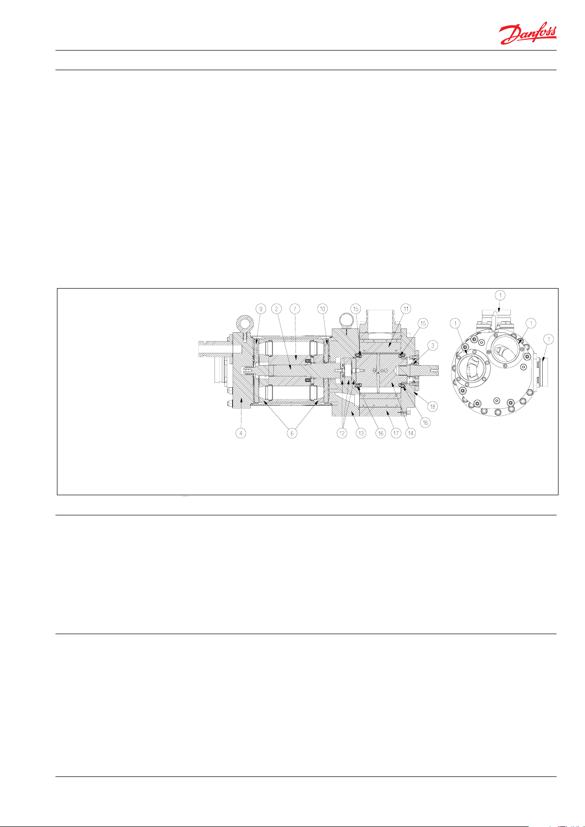
1. 3” Victaulic connections
2. Shaft
3. Low pressure shaft seal
4. Port ange
6. Valve plate
7. Cylinder barrel
9. Port plate (brine)
10. Port plate (sea water)
11. Vane s
12. Coupling
13. Intermediate ange
14. Rotor
15. Rotor element
16. Sealing plate
17. Stat or
18. Motor end ange
All parts included in the iSave 50 & 70 are
designed to provide long service life with a
constant high eciency and minimum service
required.
Unlike a centrifugal pump, it produces a similar
ow at a given speed no matter what discharge
pressure.
2. Benets • Corrossion resistance (all wetted parts are made
• Signicant power savings and low specic
energy consumption (SEC)
• Simple and space-saving installation with
both pump and pressure exchanger in one
of high corrosion-resistant materials e.g. Super
Duplex or Duplex)
• Fewer components
unit
• Simple system design and monitoring
without requirement for high-pressure ow
meters
• Simple operation with design that prevents
overspin/overushing
• Easy modular service
3. Applications
Danfoss iSave ERDs are built into a broad range
of RO desalination plant around the world.
Typical applications for iSave 50 - 70 will be:
• Containerized solutions for hotels and
resorts on islands as well as coastal regions
• Onboard systems for ships
• Oshore platforms for the oil and gas
industry
• Municipal and private waterworks
AI264763692435en-000901 | Data sheet iSave 50-70 | UK | 04.2021
3
Data sheet | iSave 50 and iSave 70
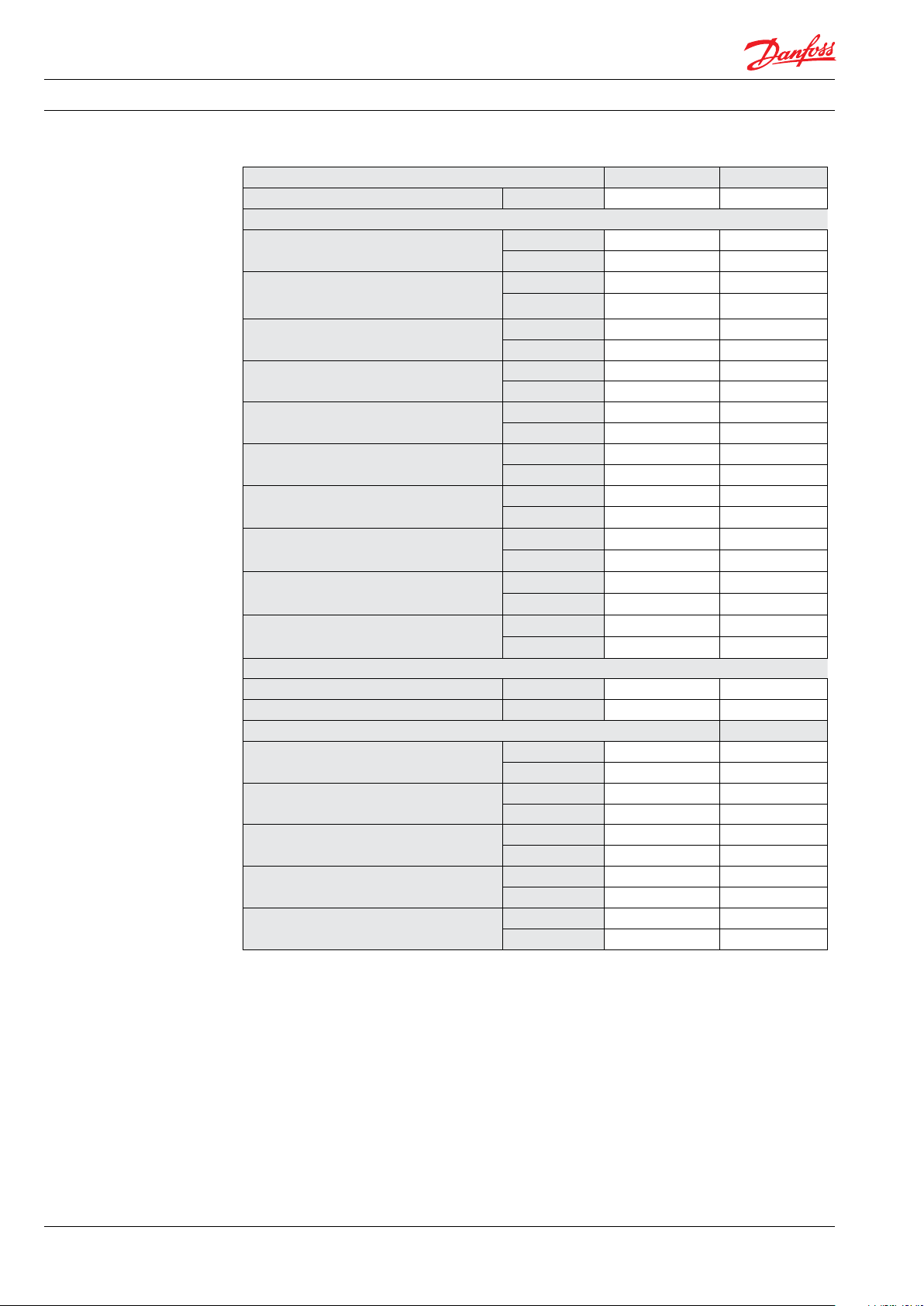
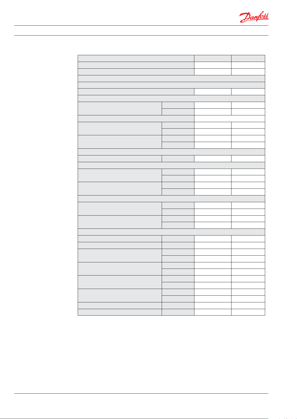
4. Technical data 4.1 iSave without motor
iSave size iSave 50 iSave 70
Code number 180F7020 180F7021
Pressure
Max. dierential pressure (HP out - HP in)
Min. pressure HP out (min. allowable working
pressure)
Max. pressure HP out (Max. allowable working
pressure, MAWP)
Min. pressure on HP in,
intermittent
Max. pressure LP in (MAWP)
Max. pressure LP in, peak
Min. allowable working pressure LP in
Max. dierential pressure (LP in - LP out)
Max. static test pressure (HP in and HP out)
Max. static test pressure (LP in and LP out)
Speed
Min. speed rpm 525 625
Max. speed rpm 650 875
Typical ow
Flow at min. speed, HP out
Flow at max. speed. HP out
Max. lubrication ow at 60 barg (871 psig)
Peak ow, LP in
Max. allowable working ow, LP in
1)
2) 3)
4)
10)
barg 5 5
psig 72 72
barg 40 40
psig 580 580
barg 83 83
psig 120 0 120 0
barg 2 2
psig 29 29
1)
barg 5 5
psig 72 72
barg 10 10
psig 145 145
barg 2 2
psig 29 29
barg 0.53 0.79
psig 7.69 11.4 6
barg 108 108
psig 1566 156 6
barg 13 13
psig 189 189
m³/ h 42 50
gpm 184 220
m³/ h 52 70
gpm 228 308
l/min 25 25
gpm 6.6 6.6
m³/ h 120 120
gpm 528 528
7)
m³/ h 57. 2 70
gpm 252 308
4
AI264763692435en-000901 | Data sheet iSave 50-70 | UK | 04.2021
Data sheet | iSave 50 and iSave 70
Technical specications
Media temperature
Ambient temperature
Filtration requirements (nominal)
Salinity increase at membrane at 40% recover y rate at
balanced ow
Weight (dry)
Weight (operation with water)
Noise
Sound pressure level L
Torque data
Max. allowable working torque
Max. starting torque (stick/slip)
o
5)
6)
9)
C 2-35 2-35
o
F 36-95 36-95
o
C 0-50 0-50
o
F 32-122 32-122
3 micron melt-blown
2-3%
kg 164 164
lb 362 362
kg 172 172
lb 379 379
8)
PA
1 m
dB(A) 83 86
Nm 170 190
lbf-ft 125 140
Nm 180 180
lbf-ft 132 132
1)
Max. allowable working pressure of continous
operation. For lower and higher pressure, please
contact Danfoss.
2)
Typical pressure level at start-up and permeate
ush.
3)
Intermittent pressure is acceptable for less than 10
minutes within a period of 6 hours.
4)
Typical average ow at 60 barg and 3 barg
dierential pressure
5)
Dependent on NaCI concentation.
6)
Please see section 7.4 ltration.
7)
Continuous operation: iSave can operate
continuously with up to 10% over ush with the
limitation that the ow rate at LP inlet shall not
exceed 70 m3/h.
8)
A-weighted sound pressure level at 1 m from the
pump unit surfaces (reference box) acc. to EN ISO
20361 section 6.2. The noise measurements are
performed acc. to EN ISO 3744:2010 on a motor-
pump-unit at max. pressure and rpm.
9)
Balanced ow: The mixing rate is dened at
balanced ow when HP-out is equal to LP-in.
10)
At system start-up: iSave can run for up to 10 min.
with 150% of max. rated ow at LP inlet. The time
where max. rated ow is exceeded should be kept
as short as possible to minimize wear.
AI264763692435en-000901 | Data sheet iSave 50-70 | UK | 04.2021
5
Data sheet | iSave 50 and iSave 70
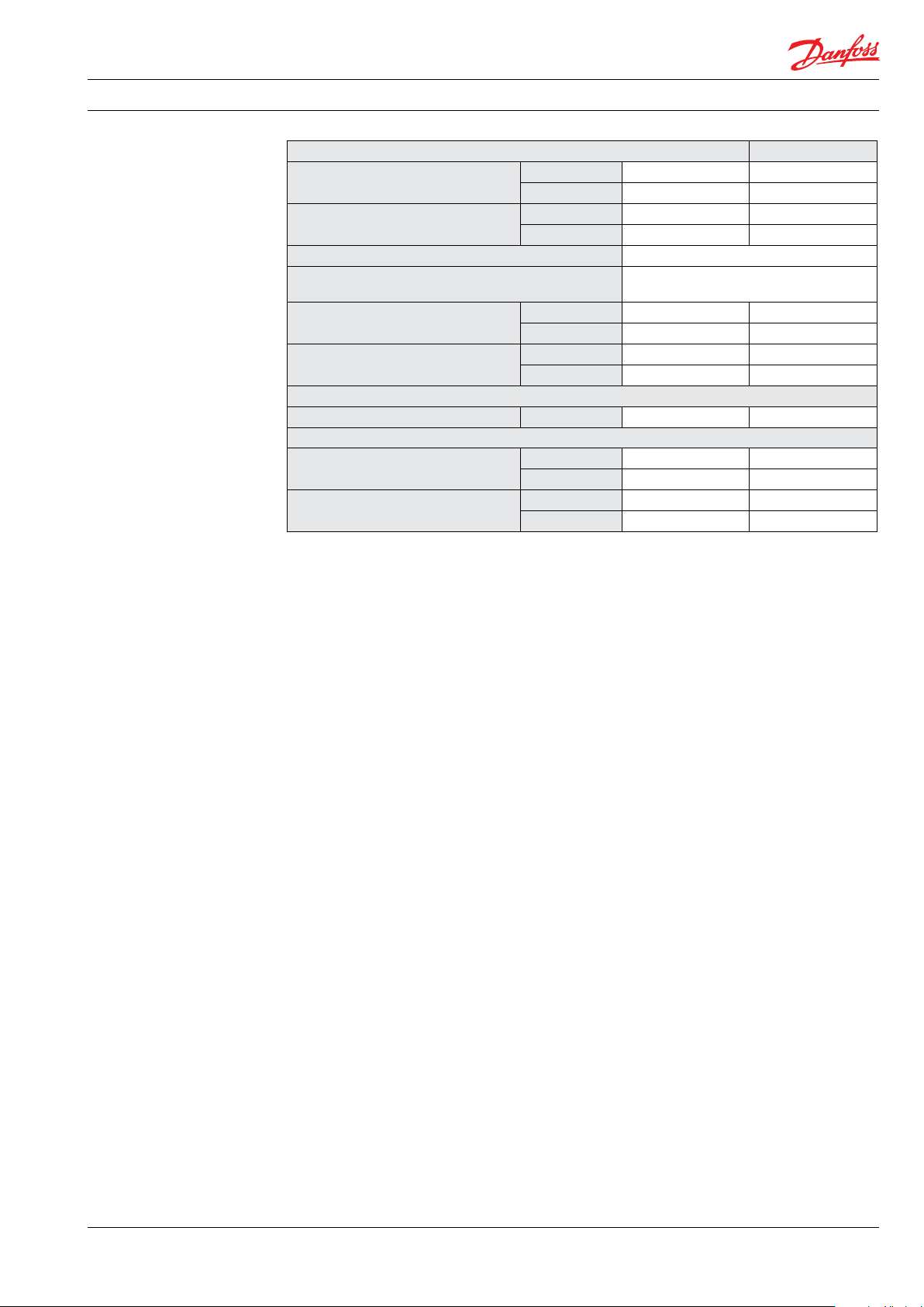
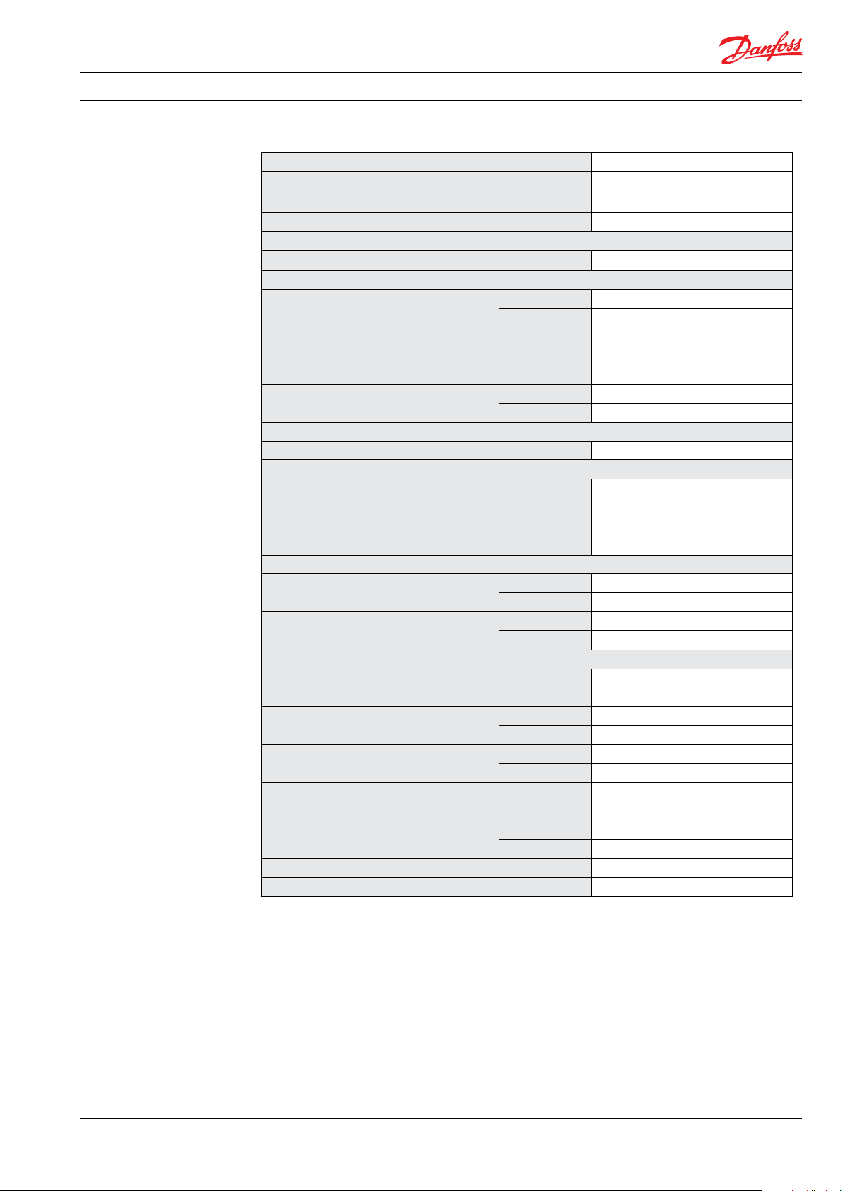
4.2 iSave with IEC motor
i
iSave size iSave 50 iSave 70
Code number (vertical) 180F7038 180F7040
Code number (horizontal) 180F7023 180 F7025
Pressure, Speed, Flow, Temperature and Torwue are identical with 180F7020 and 180F7021
Eciency
Eciency at max. speed at 60 barg (871 psig) % 93.7 92.4
Technical specications
Media temperature
Filtration requirements (nominal)
Weight (dry) vertical/horizontal
Weight (operation with water) vertical/
horizontal
Noise
Sound pressure level L
Footprint
Footprint (vertical position)
Footprint (horizontal position)
Torque data
Max. allowable working torque
Max. starting torque (stick/slip)
Motor data
Nominal speed rpm 985 985
Rated current at 400V A 37 37
Motor size
Frame size
Rated motor torque at nominal speed
Rated motor ambient temperature
Motor insulation Class B B
Motor degrees of protection IP 55 55
5)
°C 2-35 2-35
°F 36-95 36-95
6)
3 micron melt-blown
kg 441/463 441/463
lb 972/1021 972/1021
kg 470/471 470/471
lb 1036/1038 1036/1038
2)
PA
1 m
3)
dB(A) 83 86
m² 0.44 0.44
foot² 4.71 4.71
3)
m² 0.76 0.76
foot² 8.14 8.14
Nm 170 177
lbf-ft 125 130.5
Nm 180 180
lbf-ft 132 132
kW 18.5 18.5
HP 30.0 30.0
IEC 200 L 200 L
Poles 6 6
Nm 177 177
lbf-ft 130. 5 130.5
4)
°C 40 40
°F 104 104
2)
A-weighted sound pressure level at 1 m from the ERD
unit surfaces (reference box) acc. to EN ISO 20361
section 6.2. The noise measurement are performed
acc. to EN ISO 3744:2010 on an ERD with motor
(motor pump unit) from min. to max. pressure and
6)
Please see section 7.4 Filtration
7)
Typical eciency for pressure exchanger, ..
booster pump, electrical motor and VFD at 3
barg dierential pressure after a system has ...
been commissioned and run in.
speed.
3
Area covered with recommended IE3 motor
congurations (excl. of space to service the ERD)
4)
For higher temperature, contact Danfoss.
5)
Dependent on NaCI concentation.
6
AI264763692435en-000901 | Data sheet iSave 50-70 | UK | 04.2021
)
Data sheet | iSave 50 and iSave 70
4.3 iSave with NEMA motor
iSave size iSave 50 iSave 70
Code number (vertical) 180U0062 180U0064
Code number (horizontal) 180U0003 180U0005
Pressure, Speed, Flow, Temperatue and Torque are identical with 180F7020 180F7021
Eciency
Eciency at max. speed at 60 barg (871 psig)
Technical specications
Media temperature
Filtration requirements (nominal)
Weight (dry) vertical/horizontal
Weight (operation with water) vertical/
horizontal
Noise
Sound pressure level L
Footprint
Footprint (vertical position)
Footprint (horizontal position)
Torque data
Max. allowable working torque
Max. starting torque (stick/slip)
Motor data
Nominal speed rpm 118 0 118 0
Rated current at 400V A 36.2 36.2
Motor size
Frame size
Rated motor torque at nominal speed
Rated motor ambient temperature
Motor insulation Class B B
Motor degrees of protection IP 55 55
2)
A-weighted sound pressure level at 1 m from the ERD
unit surfaces (reference box) acc. to EN ISO 20361
section 6.2. The noise measurement are performed
acc. to EN ISO 3744:2010 on an ERD with motor
(motor pump unit) from min. to max. pressure and
speed.
3
Area covered with recommended IE3 motor
congurations (excl. of space to service the ERD)
4)
For higher temperature, contact Danfoss.
5)
Dependent on NaCI concentation.
7)
% 93.7 92.4
5
)
6)
°C 2-35 2-35
°F 36-95 36-95
3 micron melt-blown
kg 484/506 484/506
lb 10 67/1116 10 67/1116
kg 513/535 513/535
lb 1131/1179 1131/117 9
2)
PA
1 m
3)
dB(A) 83 86
m² 0.44 0.44
foot² 4.71 4.71
3)
m² 0.76 0.76
foot² 8.14 8.14
Nm 170 177
lbf-ft 125 130.5
Nm 180 180
lbf-ft 132 132
kW 22.5 22.5
HP 30.0 30.0
NEMA 324/6T 324/6T
Poles 6 6
Nm 179 179
lbf-ft 132 132
4)
°C 40 40
°F 104 104
6)
Please see section 7.4 Filtration
7)
Typical eciency for pressure exchanger, ..
booster pump, electrical motor and VFD at 3
barg dierential pressure after a system has ...
been commissioned and run in.
)
AI264763692435en-000901 | Data sheet iSave 50-70 | UK | 04.2021
7

Data sheet | iSave 50 and iSave 70
0
10
20
30
40
50
60
525 650
Flow [GPM]
Flow [m
3
/h]
Motor speed [rpm]
Flow curve iSave50®
5 bar
2
bar
220
176
0,0
10,0
20,0
30,0
40,0
50,0
60,0
70,0
80,0
625 875
Flow [GPM]
Flow [m
3
/h]
Motor speed [rpm]
Flow curve iSave70®
2
bar
5 bar
220
308
5. Performance curves 5.1 Flow at dierent rpm
The diagram shows that the HP ow can be
changed by changing the rotation speed of the
iSave. The ow/rpm ratio is constant, the
required ow is obtainable by changing the
rotation speed to a required value.
5.2 iSave 50 ow curves
For accurate data and advise, please contact
Danfoss High Pressure Pumps.
The iSave is delivered with a 3.1 performance
certicate according to EN10204.
5.3 iSave 70 ow curves
8
AI264763692435en-000901 | Data sheet iSave 50-70 | UK | 04.2021

Data sheet | iSave 50 and iSave 70
5.4 Torque curve for iSave 50 and iSave 70
Below curve illustrates typical values.
Torque [Nm]
200
180
160
140
120
100
80
60
40
Torque on iSave50 and iSave70
Starting torque
delta-P: 5 bar
delta-P: 4 bar
delta-P: 3 bar
delta-P: 2 bar
delta-P: 1 bar
20
0
5.5 Mixing curve
525 645 765 875
Motor speed [rpm]
Volumetric mixing versus flushing
14,0
12,0
10,0
8,0
6,0
Volumetric mixing [%]
4,0
2,0
0,0
-10 -5 0 5 10
Flush ratio (larger than 0 means overflush) [%]
AI264763692435en-000901 | Data sheet iSave 50-70 | UK | 04.2021
9

Data sheet | iSave 50 and iSave 70
6. Temperature and
corrosion
6.1 Operation
The chart below illustrates the corrosive
resistance of dierent types of stainless steel
related to NaCl concentration and temperature.
All critical parts of the iSave is made of
Super Duplex 1.4410/UNS 32 750 or Duplex
1.4462/UNS 32803.
º
80
C
Duplex
70
60
50
316L
40
30
20
100
1000
160 1600
Always ush the iSave with fresh water at
operation stop in order to minimize the risk of
crevice corrosion.
Super Duplex
-
10 000
16000
100 000
160000
CI
ppm
NaCI
ppm
7. Installation
7.1 Operation and mounting 7.2 Horizontal mount
The iSave 50 and iSave 70 can be mounted
horizontally and vertically. When mounted
vertically, the electric motor must be placed at
the top of the iSave
The iSave is delivered with a standard port
orientation. The port orientation can be changed
by the customer by rotating the combined iSave
and bell housing around the center of the motor
shaft.
10
AI264763692435en-000901 | Data sheet iSave 50-70 | UK | 04.2021

Data sheet | iSave 50 and iSave 70
See example below on how to mount the pump
and connect it to an electrical motor.
A: Flexible coupling
B: Bell housing
C: Motor shaft
7.3 Connection to inlet or discharge ports:
• When using hard piping, it is important to
follow the Guideline 180R9367 - Pipe
connection.
• When using exible hoses, it is recommened
to use Hose Whip Restraint. Also follow the
guideline 180R9084 - Right and Wrong Hose
assembly.
Note: Any axial and radial load on the shaft
must be avoided.
min. 3 - 5 mm air space
A B C
7.4 Filtration
High quality water extends the service life of the
whole system.
Water to the iSave must be ltered to 3 μm
nominal, using melt-blown depth lter with
good end sealings. Consult Danfoss for correct
choice of lter.
It is important with selection of a proper lter
and lter housing to ensure good cartridge end
sealing.
If there is a high risk of water by-pass it is
recommended to use a second stage lter
solution.
7.5 Noise
Since the iSave is mounted on a bell housing and
electric motor, the noise level should be
determined for a complete system. To minimize
vibrations and noise throughout the system, it is
improtant that a horizontal iSave unit is mounted
correctly on a frame with dampeners.
Rigid designs with metal pipes cause vibration
and noise. It is therefore recommended to use
high-pressure exible hoses between the hard
piping in the RO-plant and the iSave or to used
multiple connections with Victaulic clamps
where possible.
The noise level is inuenced by:
Speed:
• High rpm makes more uid/structure-borne
pulsations/vibrations than low rpm due to
higher frequency.
AI264763692435en-000901 | Data sheet iSave 50-70 | UK | 04.2021
As the various lters on the market dier greatly,
Danfoss High Pressure Pumps recommends
using cartridges with consistent, reliable
performance and high eciency and where
bres are blown continuously onto a central
support core. High Pressure Pumps does not
recommend cartridges requiring any type of
binders or resins.
Filters can be purchased from Danfoss
High Pressure Pumps. For more information on
the importance of proper ltration, please
consult our publication “Filtration” (code number
521B1009), which also will provide you with an
explanation of ltration denitions and a
guidance on how to select the right lter.
Pressure:
• High pressure makes more noise than low
pressure.
Mounting:
• Rigid mounting makes more noise than
exible mounting due to structure-borne
vibrations.
Connections to iSave:
• Pipes connected directly to the iSave make
more noise than exible hoses due to
structure-borne vibrations.
• Variable frequency drives (VFD):
Motors regulated by VFDs can increase noise
level if the VFD does not have the right
settings.
11

Data sheet | iSave 50 and iSave 70
7.5 RO systems with an iSave
VFD
22
M
4
2
26
Media filter
A
B C
Filter
3 micron
nominel
PI
Fresh water
permeate flush
Filter
10 micron
absolut
PI
F
*
12
PI
PS
21
24
19
*
Second stage filter: If recommended housing des ign and cartridges are not used, a second stage filt er is required
3
LP in
PI
PS
F
1
HP out
11
M
4
26
iSave
HP in
M
VFD
23 23
25
18
25
18
HP out
HP in
M
VFD
VFD
5
PI
PS
13
14
PS
PI
6
7
20
F
22
Full flow
cleaning/CIP
1011
PI
15
17
Permeate
F
Flowmeter
8
9
16
28
CIP
27
Drain
Explanation of P&ID setup
D. Inlet ow control and mixing:
A. Inlet lter:
Place inlet lters on LP string in front of the
iSave (11). Please see Guide line 521B1009 on
Filtration.
To balance LP ow up against HP ow on the
iSave and control mixing, place a
owmeter on low-pressure inlet (12) or low
pressure outlet (20) of the iSave.
If recommended housing design and
cartridges are not used, a second stage
lter is required, see above (*).
Thoroughly clean pipes and ush system
prior to start-up.
E. Outlet pressure control:
In order to control the inlet pressure ne eded a
back pressure valve (15) must be installed in
the common outlet pipe from the iSaves. The
valve should be designed to control ow.
B. Inlet pressure:
Must assure that iSave is running according to
specications. Refer to iSave data sheet.
It is recommended to use a manual valve with
lock function or an automatic controlled
valve.
Required: Must assure min. pressure to avoid
cavitation.
Recommended: Must assure max. pressure to
avoid hydraulic and mechanical overload.
(13) used for iSave 21 and iSave 40.
(24) used for iSave 50 and iSave 70.
F. Variable speed and overload protection:
Install a VFD to control the speed of the iSave
and protect it against mechanical overload.
See instruction 180R9372 for guidance of VFD
settings.
C. Piping and hoses:
Dimension the piping to obtain minimum
G. LP discharge ow control:
See “E”.
pressure loss (large ow, minimum pipe
length, minimum number of bends/
connections and ttings to prevent pressure
loss and ow turbulence). Use exible hoses
to minimize vibrations and noise. Please
consult the Danfoss Hoses and Hose Fittings
H. Air venting:
Install an air bleed valve (8) on the highest
point of the high-pressure piping to ensure
the air is purged from the system before
startup.
data sheet (521B0909 ) and Right and wrong
Hose assembly (180R9084) for guidance.
12
AI264763692435en-000901 | Data sheet iSave 50-70 | UK | 04.2021

Data sheet | iSave 50 and iSave 70
I. Pressure relief (high pressure):
The pressure relief valve (6) protects the whole
system against pressure overload and relieves
the water if the pressure exceeds the maximum set pressure. If the high-pressure pump
is a positive displacement pump, the pump
can built up a very high pressure that will
exceed mechanical strength of the membrane
housing, pipes and other accessories. When
using Danfoss APP pumps with Danfoss VCM
check valves, it is recommended to place a
pressure relief valve or pressure safety valve as
illustrated. In case the Danfoss check valves
are not used, the valve must be placed
between pump and check valve (See
180R9371, Design Guide Pressure saftey valve
in seawater RO sytem for more details).
J. Pressure relief (low pressure):
The pressure relief valve or pressure safety
valve (19) protects the low-pressure pipes
against pressure overload and relieves the
water if the pressure exceeds the maximum
allowable pressure.
For a more eleborate description of the P&ID
setup, please consult the Danfoss Design Guide
Piping & Instrumentation Diagram (P&ID)
(180R9370) or contact Danfoss.
The iSave 50 and iSave 70 can be mounted in
parallel. For more information, please see
“Design Guide Parallel-coupled APP and iSave”
-180R9354 or contact Danfoss.
AI264763692435en-000901 | Data sheet iSave 50-70 | UK | 04.2021
13

Data sheet | iSave 50 and iSave 70
8. Dimensions and
connections
8.1 iSave 50-70
without electric motor
14
AI264763692435en-000901 | Data sheet iSave 50-70 | UK | 04.2021

Data sheet | iSave 50 and iSave 70
8.2 iSave 50-70 with with IE3 motor 18.5 kW
on base frame vertical_front mounted
AI264763692435en-000901 | Data sheet iSave 50-70 | UK | 04.2021
15

Data sheet | iSave 50 and iSave 70
8.3 iSave 50-70 with with IE3 motor 18.5 kW
on base frame vertical_back mounted
16
AI264763692435en-000901 | Data sheet iSave 50-70 | UK | 04.2021

Data sheet | iSave 50 and iSave 70
8.4 iSave 50-70
with with IE3 motor 18.5 kW
on base frame horizontal
AI264763692435en-000901 | Data sheet iSave 50-70 | UK | 04.2021
17

Data sheet | iSave 50 and iSave 70
8.4 iSave 50-70 with NEMA motor 30 HP
on base frame vertical - front mounted
AI264763692435en-000901 | Data sheet iSave 50-70 | UK | 04.2021
18

Data sheet | iSave 50 and iSave 70
8.5 iSave 50-70 with NEMA motor 30 HP
on base frame vertical - back mounted
AI264763692435en-000901 | Data sheet iSave 50-70 | UK | 04.2021
19

Data sheet | iSave 50 and iSave 70
8.5 iSave 50-70
with NEMA motor 30 HP
on base frame horizontal
20
AI264763692435en-000901 | Data sheet iSave 50-70 | UK | 04.2021

Data sheet | iSave 50 and iSave 70
9. Service 9.3 Maintenance
9.1 Warranty
The Danfoss iSave is designed for long operation,
low maintenance and reduced lifecycle costs.
Periodic inspections are required to ensure worn
parts (if any), are replaced in due time. Opera-
tional conditions such as water quality should be
Provided that the iSave has been running
according to the Danfoss specications, Danfoss
guarantees one year service-free operation,
taken into consideration when determining the
frequency of the inspections. Danfoss recom-
mends yearly inspections.
however, max. 18 months from date of
production.
It is recommended to order the purpose-
designed tool kit.
9.2 Operational conditions of concern
Particular attention should be paid to the
following factors to avoid increased wear and
spare parts costs:
9.4 Repair assistance
In case of irregular function of the Danfoss RO
components, please contact Danfoss High
Pressure Pumps.
- Insucient ltration
- Insucient bleeding and venting
- Running at speeds outside specicat
tions
- Wrong direction of rotation
- Insu cient ushing or periods o f standstill with
sea water inside the iSave.
10. Accessories
Description Type Code no.
11. Useful documents
3” Inlet hose kit - 2 m (79”) 6 barg (87 psig) 3” Victaulic, style 77 180Z0144
3” Outlet hose - 1 m (39.4”) 80 barg (1160 psig) 3” Victaulic, style 77 180Z0611
3” Outlet hose - 1.79 m (70.0”) 80 barg (1160 psig) 3” Victaulic, style 77 180Z0612
Coupling iSave 50 - iSave 70 Softex 55H7-32H7 180Z4003
Base plate horizontal IEC200/NEMA324TC 180Z4007
Base plate vertical IEC200/NEMA324TC 180Z4025
Literature number Description
180R9213 Start and stop of the SWRO with iSave
180 R9214 Membrane cleaning of the RO system with the iSave
180R9354 Parallel coupled APP and iSave
180R9367 Pipe connections
180R9371 Pressure safety valve in the SWRO system
180R9372 APP and iSave overload protection
180R9370 Review sheet P&ID
521B1009 Filtration
iSave selection tool (hpp.danfoss.com)
AI264763692435en-000901 | Data sheet iSave 50-70 | UK | 04.2021
21

Danfoss A/S
High Pressure Pumps
DK-6430 Nordborg
Denmark
Danfoss ca n accept no respons ibility for pos sible errors in ca talogues, bro chures and other pr inted material. Da nfoss reserves t he right to alter its p roducts with out notice.
This also a pplies to produc ts already on ord er provided that su ch alterations ca n be made without su bsequential cha nges being nece ssary in speci cations alread y agreed.
All trade marks in this mate rial are proper ty of the respec tive companies . Danfoss and the Dan foss logotyp e are trademark s of Danfoss A/S. Al l rights reserv ed.
© Danfoss | DCS (IM) | 2021.04
AI264763692435en-000901 | Data sheet iSave 50-70 | UK | 22
 Loading...