

Page 1
Frontpage
Operating guide
Manual del usuario
Energy Recovery Device
Manual de instalación,
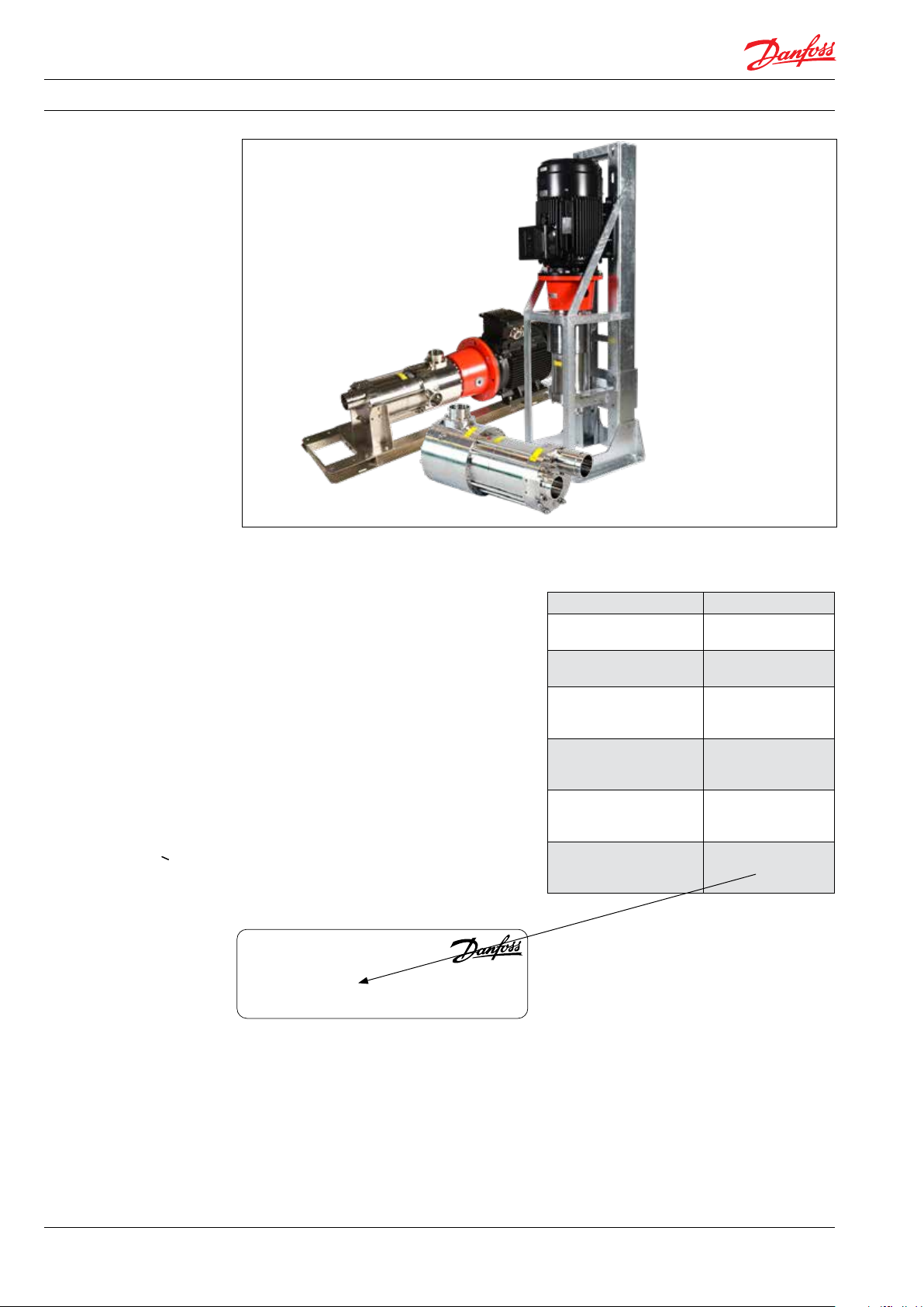
iSave 50-70
Installation, Operation and
funcionamiento y mantenimiento
Maintenance Manual
iSave 40
hpp.danfoss.com
isave.danfoss.com
Page 2

Operating guide | iSave 50 - 70
Table of Contents 1. Validity . . . . . . . . . . . . . . . . . . . . . . . . . . . . . . . . . . . . . . . . . . . . . . . . . . . . . . . . . . . . . . . . . . . . . . . . . . . . . . . . . 4
2. Introduction . . . . . . . . . . . . . . . . . . . . . . . . . . . . . . . . . . . . . . . . . . . . . . . . . . . . . . . . . . . . . . . . . . . . . . . . . . . .5
2.1 General. . . . . . . . . . . . . . . . . . . . . . . . . . . . . . . . . . . . . . . . . . . . . . . . . . . . . . . . . . . . . . . . . . . . . . . . . . . . . . . . .5
2.2 Target group. . . . . . . . . . . . . . . . . . . . . . . . . . . . . . . . . . . . . . . . . . . . . . . . . . . . . . . . . . . . . . . . . . . . . . . . . . . . 5
2.3 Symbols . . . . . . . . . . . . . . . . . . . . . . . . . . . . . . . . . . . . . . . . . . . . . . . . . . . . . . . . . . . . . . . . . . . . . . . . . . . . . . . . 5
2.4 Manufacturer and customer service address . . . . . . . . . . . . . . . . . . . . . . . . . . . . . . . . . . . . . . . . . . . . .5
2.5 Country specific information . . . . . . . . . . . . . . . . . . . . . . . . . . . . . . . . . . . . . . . . . . . . . . . . . . . . . . . . . . . . 5
2.5.1 United Kingdom . . . . . . . . . . . . . . . . . . . . . . . . . . . . . . . . . . . . . . . . . . . . . . . . . . . . . . . . . . . . . . . . . . . . . . . .5
2.6 Additional technical documents. . . . . . . . . . . . . . . . . . . . . . . . . . . . . . . . . . . . . . . . . . . . . . . . . . . . . . . . . 5
3. Safety . . . . . . . . . . . . . . . . . . . . . . . . . . . . . . . . . . . . . . . . . . . . . . . . . . . . . . . . . . . . . . . . . . . . . . . . . . . . . . . . . .6
3.1 General ............................................................................... . 6
3.2 Intended use. . . . . . . . . . . . . . . . . . . . . . . . . . . . . . . . . . . . . . . . . . . . . . . . . . . . . . . . . . . . . . . . . . . . . . . . . . . .6
3.3 Application range . . . . . . . . . . . . . . . . . . . . . . . . . . . . . . . . . . . . . . . . . . . . . . . . . . . . . . . . . . . . . . . . . . . . . . .6
3.4 Preferred system design. . . . . . . . . . . . . . . . . . . . . . . . . . . . . . . . . . . . . . . . . . . . . . . . . . . . . . . . . . . . . . . . . 6
4. Arrival, inspection, handling and storage . . . . . . . . . . . . . . . . . . . . . . . . . . . . . . . . . . . . . . . . . . . . . . . .7
4.1 Arrival inspection . . . . . . . . . . . . . . . . . . . . . . . . . . . . . . . . . . . . . . . . . . . . . . . . . . . . . . . . . . . . . . . . . . . . . . .7
4.2 Return to the supplier . . . . . . . . . . . . . . . . . . . . . . . . . . . . . . . . . . . . . . . . . . . . . . . . . . . . . . . . . . . . . . . . . . .7
4.3 Handling. . . . . . . . . . . . . . . . . . . . . . . . . . . . . . . . . . . . . . . . . . . . . . . . . . . . . . . . . . . . . . . . . . . . . . . . . . . . . . . . 7
4.4 Assembly iSave on electric motor. . . . . . . . . . . . . . . . . . . . . . . . . . . . . . . . . . . . . . . . . . . . . . . . . . . . . . . . 8
4.5 Storage . . . . . . . . . . . . . . . . . . . . . . . . . . . . . . . . . . . . . . . . . . . . . . . . . . . . . . . . . . . . . . . . . . . . . . . . . . . . . . . . .9
4.6 Outdoor storage . . . . . . . . . . . . . . . . . . . . . . . . . . . . . . . . . . . . . . . . . . . . . . . . . . . . . . . . . . . . . . . . . . . . . . . .9
5. Technical data and design review. . . . . . . . . . . . . . . . . . . . . . . . . . . . . . . . . . . . . . . . . . . . . . . . . . . . . . .10
5.1 Design details. . . . . . . . . . . . . . . . . . . . . . . . . . . . . . . . . . . . . . . . . . . . . . . . . . . . . . . . . . . . . . . . . . . . . . . . . .10
5.2 Sound level of the iSave . . . . . . . . . . . . . . . . . . . . . . . . . . . . . . . . . . . . . . . . . . . . . . . . . . . . . . . . . . . . . . . .10
5.3 Materials. . . . . . . . . . . . . . . . . . . . . . . . . . . . . . . . . . . . . . . . . . . . . . . . . . . . . . . . . . . . . . . . . . . . . . . . . . . . . . .10
5.4 Temperature and corrosion. . . . . . . . . . . . . . . . . . . . . . . . . . . . . . . . . . . . . . . . . . . . . . . . . . . . . . . . . . . . . 11
5.5 Dimensions and weights . . . . . . . . . . . . . . . . . . . . . . . . . . . . . . . . . . . . . . . . . . . . . . . . . . . . . . . . . . . . . . . 11
5.6 Electrical motor data . . . . . . . . . . . . . . . . . . . . . . . . . . . . . . . . . . . . . . . . . . . . . . . . . . . . . . . . . . . . . . . . . . .11
5.7 How does the iSave work?. . . . . . . . . . . . . . . . . . . . . . . . . . . . . . . . . . . . . . . . . . . . . . . . . . . . . . . . . . . . . . 11
5.8 Seawater quality . . . . . . . . . . . . . . . . . . . . . . . . . . . . . . . . . . . . . . . . . . . . . . . . . . . . . . . . . . . . . . . . . . . . . . . 12
5.8.1 Pre-filtration . . . . . . . . . . . . . . . . . . . . . . . . . . . . . . . . . . . . . . . . . . . . . . . . . . . . . . . . . . . . . . . . . . . . . . . . . . .12
5.8.2 Air bubbles . . . . . . . . . . . . . . . . . . . . . . . . . . . . . . . . . . . . . . . . . . . . . . . . . . . . . . . . . . . . . . . . . . . . . . . . . . . .12
5.8.3 Chemicals. . . . . . . . . . . . . . . . . . . . . . . . . . . . . . . . . . . . . . . . . . . . . . . . . . . . . . . . . . . . . . . . . . . . . . . . . . . . . .12
5.8.4 Initial start up and flushing . . . . . . . . . . . . . . . . . . . . . . . . . . . . . . . . . . . . . . . . . . . . . . . . . . . . . . . . . . . . .12
5.9 Initial start up and setting of safety . . . . . . . . . . . . . . . . . . . . . . . . . . . . . . . . . . . . . . . . . . . . . . . . . . . . .12
5.10 Flushing . . . . . . . . . . . . . . . . . . . . . . . . . . . . . . . . . . . . . . . . . . . . . . . . . . . . . . . . . . . . . . . . . . . . . . . . . . . . . . . 13
5.11 CIP or membrane cleaning . . . . . . . . . . . . . . . . . . . . . . . . . . . . . . . . . . . . . . . . . . . . . . . . . . . . . . . . . . . . .13
5.12 High pressure remains after shutdown. . . . . . . . . . . . . . . . . . . . . . . . . . . . . . . . . . . . . . . . . . . . . . . . . .13
5.13 Over-pressurisation caused by low pressure isolation . . . . . . . . . . . . . . . . . . . . . . . . . . . . . . . . . . .13
5.14 Over-pressurisation caused by high-pressure pump. . . . . . . . . . . . . . . . . . . . . . . . . . . . . . . . . . . . .13
5.15 Preferred system design and P&ID . . . . . . . . . . . . . . . . . . . . . . . . . . . . . . . . . . . . . . . . . . . . . . . . . . . . . .13
6. On-site installation . . . . . . . . . . . . . . . . . . . . . . . . . . . . . . . . . . . . . . . . . . . . . . . . . . . . . . . . . . . . . . . . . . . . .14
6.1 Design details. . . . . . . . . . . . . . . . . . . . . . . . . . . . . . . . . . . . . . . . . . . . . . . . . . . . . . . . . . . . . . . . . . . . . . . . . .14
6.2 Installation and alignment . . . . . . . . . . . . . . . . . . . . . . . . . . . . . . . . . . . . . . . . . . . . . . . . . . . . . . . . . . . . .14
6.3 Orientation . . . . . . . . . . . . . . . . . . . . . . . . . . . . . . . . . . . . . . . . . . . . . . . . . . . . . . . . . . . . . . . . . . . . . . . . . . . .14
6.4 Piping and joints . . . . . . . . . . . . . . . . . . . . . . . . . . . . . . . . . . . . . . . . . . . . . . . . . . . . . . . . . . . . . . . . . . . . . . .14
6.5 Mounting of coupling . . . . . . . . . . . . . . . . . . . . . . . . . . . . . . . . . . . . . . . . . . . . . . . . . . . . . . . . . . . . . . . . . .15
6.6 Accessibility . . . . . . . . . . . . . . . . . . . . . . . . . . . . . . . . . . . . . . . . . . . . . . . . . . . . . . . . . . . . . . . . . . . . . . . . . . .15
6.7 Drives . . . . . . . . . . . . . . . . . . . . . . . . . . . . . . . . . . . . . . . . . . . . . . . . . . . . . . . . . . . . . . . . . . . . . . . . . . . . . . . . .15
6.7.1 Electric motor. . . . . . . . . . . . . . . . . . . . . . . . . . . . . . . . . . . . . . . . . . . . . . . . . . . . . . . . . . . . . . . . . . . . . . . . . .15
6.7.2 Speed control. . . . . . . . . . . . . . . . . . . . . . . . . . . . . . . . . . . . . . . . . . . . . . . . . . . . . . . . . . . . . . . . . . . . . . . . . .15
6.7.3 Starting torque on the iSave. . . . . . . . . . . . . . . . . . . . . . . . . . . . . . . . . . . . . . . . . . . . . . . . . . . . . . . . . . . .15
6.7.4 Torque overload pretection on the iSave. . . . . . . . . . . . . . . . . . . . . . . . . . . . . . . . . . . . . . . . . . . . . . . .16
7. Commissioning, start-up and shutdown ................................................16
7.1 Safety regulations......................................................................16
7.2 Support................................................................................16
7.3 Commissioning ........................................................................16
2
180R9357 | AQ265943679828en-001001 IOM iSave 50 - 70 | 02.2022
Page 3

Operating guide | iSave 50 - 70
8. Service/Maintenance...................................................................17
8.1 Safety regulations......................................................................17
8.2 Support................................................................................17
8.3 Maintenance schedule .................................................................17
8.4 Recommended service intervals on internal parts .......................................18
8.5 Lubrication of bearings in electric motor................................................18
9. Trouble shooting.......................................................................19
9.1 Safety regulations......................................................................19
10. Appendices............................................................................21
10.1 Data sheet iSave 50-70 - (521B1378)) ....................................................23
10.2 Start and stop procedures (180R9213). ..................................................45
10.3 Membrane cleaning of the RO system with iSave unit (180R9214) . ......................51
10.4 APP pumps and iSave overload protection(180R9372)...................................57
10.5 Hose assembly and installation (180R9084) .............................................67
10.6 iSave part list 50-70 (521B1428) .........................................................75
10.7 Operating- and maintenance instruction, electric motor (180R9230).....................87
180R9357 | AQ265943679828en-001001 IOM iSave 50 - 70 | 02.2022
3
Page 4
Operating guide | iSave 50 - 70
1. Validity Document information and copyright
Installation, Operation and Maintenance
Manual.
Danfoss can accept no responsibility for possible
errors in the manual and instructions. Danfoss
reserves the right to alter its products without
notice. This also applies to products already on
order provided that such alterations can be
made without subsequential changes being
necessary in specifications already agreed.
All rights reserved. Contents provided herein
must neither be distributed, copied, reproduced,
edited or processed for any other purpose, nor
otherwise translated or published without
Danfoss’ express written consent.
PUMP
Type iSave 50 ERD
Code no. 180FXXXX
Serial no. XXXXXX02-XXX
MADE IN DENMARK
Danfoss A/S, 6430 Nordborg, Denmark
This manual is valid for iSave 50 -70
Code No./Description Serial no.
180F7020
iSave 50 without motor
180F7021
iSave 70 without motor
180F7038
iSave 50 Vertical
(IEC motor)
180F7023
iSave 50 horizontal
(IEC motor)
180F704 0
iSave 70 vertical
(IEC motor)
180F7025
iSave 70 horizontal
(IEC motor)
XXXXXX02-XXX
XXXXXX02-XXX
XXXXXX02-XXX
XXXXXX02-XXX
XXXXXX02-XXX
XXXXXX02-XXX
The serial number is referring to the Serial no. on
the product label. The digits shown (02) indicate
the version number of the pump.
This document is only valid for ERD version 2
and upwards.
4
180R9357 | AQ265943679828en-001001 IOM iSave 50 - 70 | 02.2022
Page 5
Operating guide | iSave 50 - 70
2. Introduction 2.1 General
iSave is manufactured by Danfoss A/S, and is sold
and marketed by a net of authorised distributors
world wide.
This manual contains the necessary instructions
for the installation, operation and service of the
iSave.
All personnel who are responsible for the
operation and maintenance of the iSave unit
must read and fully understand these
instructions, especially the section “Safety”
before:
• Transporting of the iSave unit.
• Lifting the unit.
• Installing the iSave unit on a frame.
• Connecting the iSave unit to the fluid
system.
• Connecting the electrical motor and
instrumentation.
• Commissioning the unit.
• Servicing the iSave unit, mechanics and
electrics.
• Decommissioning the iSave unit.
Ensure that these instructions are always readily
available to all personnel concerned.
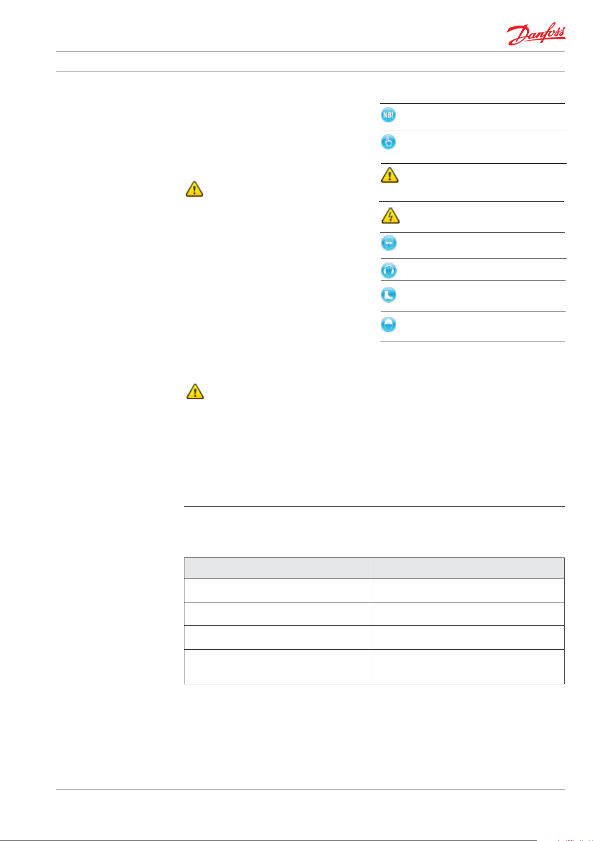
2.3 Symbols
Indicates something to be noted by
the reader.
Indicates a situation which will or
couldresult in damage to the iSave
and its function.
Indicates a situation which will or
could result in personal injury and/or
damage to the iSave.
Electrical hazard. Indicates a high-voltage
warning
Safety glasses required
Hearing protection required
Safety shoes required
Safety helmet required
2.4 Manufacturer and customer service
Danfoss A/S
High Pressure Pumps
DK-6430 Nordborg, Dinamarca
Tel.: +45 7488 2222
E-mail: highpressurepumps@danfoss.com
Homepage: hpp.danfoss.com
2.2 Target group
This manual is intended for use by personnel
with qualified training and experience in the
operation and maintenance of a Sea Water
Reverse Osmosis (SWRO) or Brackish Water
Reverse Osmosis (BWRO) system.
2.5 Country specific information
2.5.1 United Kingdom
Danfoss Ltd.
22 Wycombe End
HP9 1NB Beaconsfield
United Kingdom
2.6 Additional technical documents
Below documents are not present in this Operating guide. Please contact Danfoss.
Document name Content
Service guide: 180R9387
Disassembling and assembling
Design guide: 180R9367
Pipe connection
Guide line: 180R9371
Pressure safety valve in SWRO systems
Guide line: 180R9370
Review sheet P&ID
Description of how to disassemble and assemble the iSave
Design guide on how to make har piping
with Victaulic clamps
Guide line on how to evaluate if a safty
valve is needed in a SWRO system
Detailed description about the need for
each individual component in the preferred
P&ID
180R9357 | AQ265943679828en-001001 IOM iSave 50 - 70 | 02.2022
5
Page 6
Operating guide | iSave 50 - 70
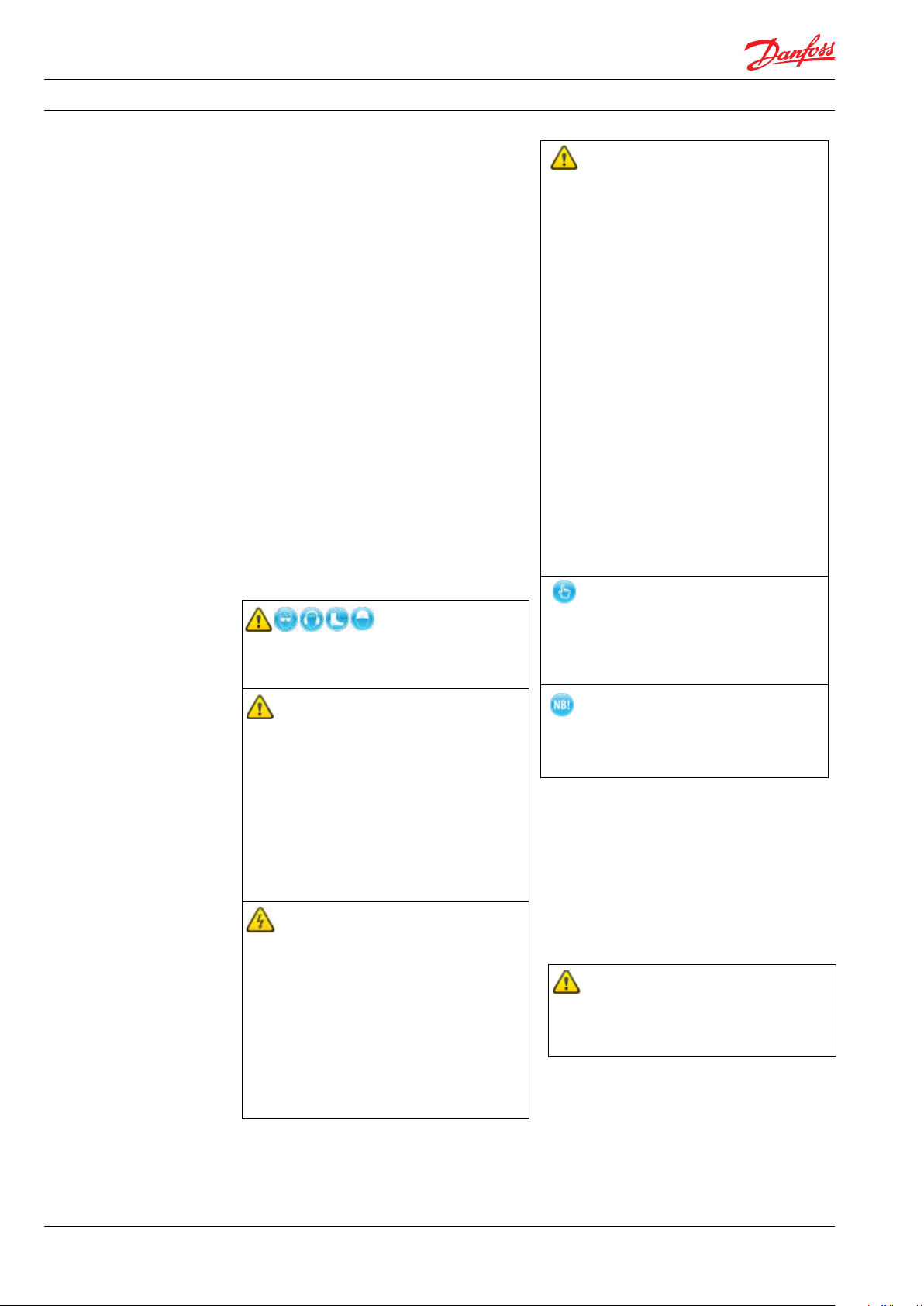
3. Safety 3.1 General
The iSave must not be used for other
purposes than those recommended and
specified without first consulting your local
iSave distributor.
This manual must be read and completely
understood by the responsible specialist
personnel prior to installation and
commissioning.
Use of this manual does not relieve operation
and maintenance personnel of the responsibility
of applying normal good judgment in the
operation and care of this product and its
components.
This manual must be available to all personnel
concerned at the site at all time.
An iSave must always be installed and used
in accordance with existing national and local
sanitary and safety regulations and laws. It is the
responsibility of the safety officer or the chief
operator to assure compliance with all local
regulations that are not taken into account in this
manual.
The iSave is a rotating machine that typically
operates at high pressure.
• Improper installation can cause fatal
injuries.
• The iSave must not operate outside the
application range.
• During the initial start-up, slowly raise the
pressure of the system and adjust the
over-pressure protection equipment for
proper limit settings.
• Make sure that the pressure is released
from the iSave before the iSave is
disconnected from any pipe or hose
connections.
• Make sure that the iSave can be drained
without injuring anyone and without
contaminating nearby equipment or the
environment.
• Before intervening in the iSave/system,
the power must be shut off and the
starting device must be locked. When
intervening in the iSave unit, follow the
instructions for Service/Maintenance,
chapter 8.
• A failure not to follow the instructions can
result in personal injury and/or damage to
the iSave. It will also invalidate the
warranty.
Always wear suitable safety and lifting
equipment when handling the iSave.
• Bolt the iSave properly to the base before
start-up to avoid personal injury and/or
damage to the iSave.
• The pipe connections to the iSave must be
stress-free mounted, securely fastened to
the iSave and well supported. Improper
installation will or could result in personal
injury and/or damage to the iSave.
• Proper installation and care of shutdown
devices and over-pressure protection
equipment is essential.
• All electrical installation work must be
carried out by authorised personnel in
accordance with EN60204-1 and/or local
regulations.
• Install a lockable circuit breaker to avoid
inadvertent starting. Protect the motor and
other electrical equipment from overloads
with suitable
• equipment.
• The electric motors must be supplied with
adequate cooling ventilation.
• The iSave must never run dry. Dry running
produces heat and will cause damage to
internal parts.
• If the iSave does not function satisfactorily, contact your local iSave distributor.
Use of this manual does not relieve
operation and maintenance personnel of
the responsibility of applying normal
good judgment in the operation and care
of this product.
3.2 Intended use
The iSave is designed for use as energy recovery
device in Sea Water Reverse Osmosis (SWRO) or
Brackish Water Reverse Osmosis (BWRO) system.
The iSave must not be used for other purposes
than recommended and quoted for without
consulting your local iSave distributor.
3.3 Application range
For application range see data sheet 521B1378
available in appendix 10.1.
Applications not suitable for the iSave
can cause damages to the iSave unit,
with risk of personal injury.
6
180R9357 | AQ265943679828en-001001 IOM iSave 50 - 70 | 02.2022
Page 7
Operating guide | iSave 50 - 70
3.4 Preferred system design
Danfoss recommends building systems with
a high degree of safety. Our preferred system
design can be found in the data heet in appendix
10.1.
• It is always the system builders’
responsibility that the system design does
not cause any form of hazard and are
adapted to local regulations.
• Proper installation and care of shutdown
devices and over-pressure protection
equipment is essential.
4. Arrival inspection,
handling and storage
4.1 Arrival inspection
The iSave is packed in a wood container.
The iSave ports connector are protected by
plastic caps that protect the iSave against dust
and particles. Do not remove the caps before the
system have been flushed and the iSave can be
installed.
Remove all packing materials immediately after
delivery. Immediately check the shipment for
damage on arrival and make sure that the name
plate/type designation is in accordance with the
packing slip and your order.
In case of damage and/or missing parts, a report
should be drawn up and presented o the carrier
at once.
The identification label on the iSave states the
specific type, the serial number and the code
number of the iSave; see fig. below.
The last three digits of the Serial No. indicate the
week and year of production.
PUMP
Type iSave 50 ERD
Code no. 180FXXXX
Serial no. XXXXXX02-XXX
4.2 Return to the supplier
Flush the iSave with clean water. Drain the iSave
and plug the port connections with a cap/cover.
MADE IN DENMARK
Danfoss A/S, 6430 Nordborg, Denmark
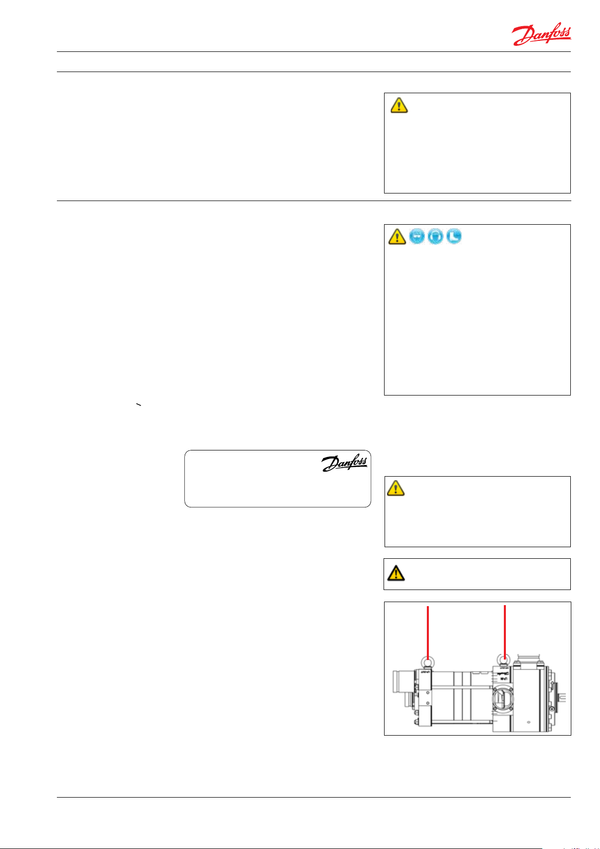
4.3 Transport and Handling
•
• Personnel involved in lifting and
transportation of the equipment must be
trained in proper handling and safety
procedures.
• Observe the local regulations regarding
lifting.
• Use suitable, permitted lifting equipment.
• The iSave (set) could slip the lifting
arrangement.
• Be aware of individuals located in the
operation area while lifting the
component.
The weight of the iSave including electric
motor can be found in the datasheet.
All parts weighing more than 20 kg (44 lb)
must be lifted using lifting slings and suitable
lifting devices, e.g. an overhead crane
or fork lift.
Do not use connections/nozzles for
lifting. Do not use only one sling! Make
sure that the load is balanced before
attempting the lift.
Pack the iSave into a suitable container and make
sure that it is suitably fastened to the container.
Please coordinate the shipment with your local
authorized distributor or contact anfoss direct to
obtain a return shipping address.
180R9357 | AQ265943679828en-001001 IOM iSave 50 - 70 | 02.2022
When lifting the ERD without motor use
the lifting eye
s.
When you have finished using the lifting eyes,
remove them to prevent corrosion.
7
Page 8
Operating guide | iSave 50 - 70
When the iSave is mounted with an electric
motor (horizontal), it must not be lifted in the
lifting eye. An iSave assembled with motor
(horizontal) must be handled by using two slings
around the unit. One sling must be attached to
the electric motor and one sling
around the iSave. Make sure that the unit/load is
balanced before lifting. The centre of the mass
may vary.
Some motors and pumps have specific lifting
eyes.
Do not use connections/nozzles for lifting!
Always use two slings.
Lifting the iSave with electric motor (vertical):
The two lifting belts around the bell housing
before lifting the unit.
Lift the iSave unit with only one fastening point.
Incorrect lifting can result in personal injury and/
or damage of the unit.
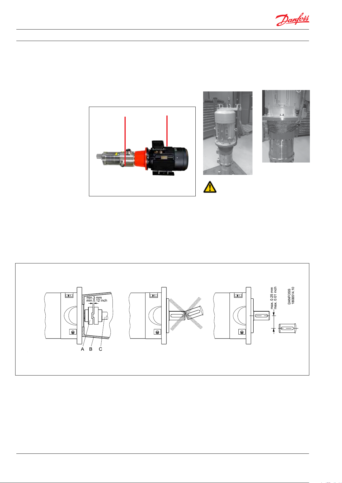
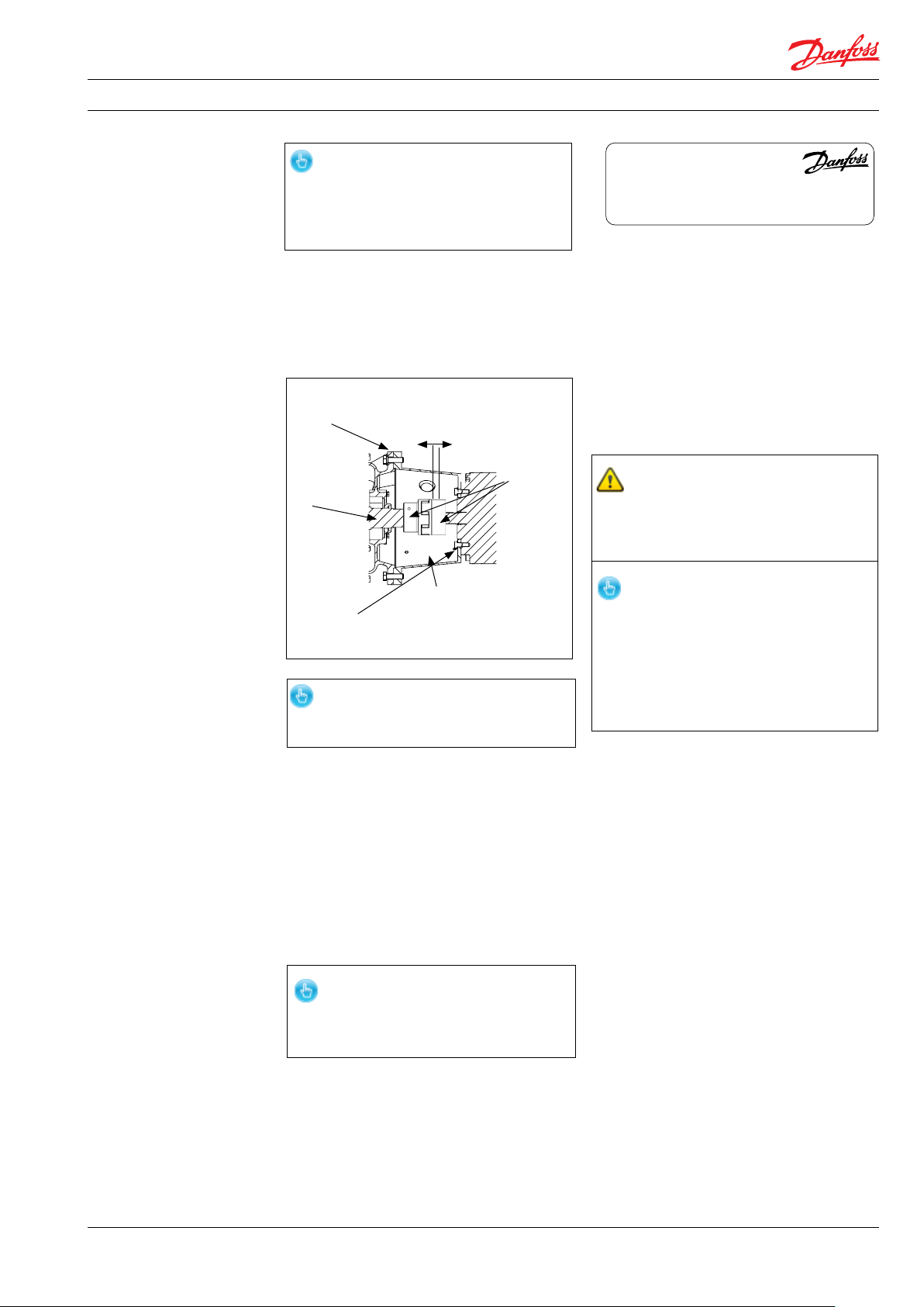
4.4 Assembly iSave to electric motor
A: Elastic coupling
B: Bell housing
C: iSave shaft
D. iSave flange
1. Mount the coupling flush or maximum 1
mm offset from the iSave shaft end. Ensure
an air gap between coupling parts of 3-5
mm (0.12-0.2 inch).
2. Mount the bell housing on iSave. Secure
nuts with the right torque.
3. Measure the longest distance “A” from top
of bell housing to the button of coupling
claw.
4. Mount the coupling on motor shaft. Ensure
the coupling and motor flange are not in
contact with each other.
5. Measure from motor flange to the top of the
coupling. That measurement “B” shall be 3-5
mm (0.12-0.2 inch) shorter than the measure
me nt “A”.
(“A” and “B” can be found on the next page).
8
180R9357 | AQ265943679828en-001001 IOM iSave 50 - 70 | 02.2022
Page 9
Operating guide | iSave 50 - 70
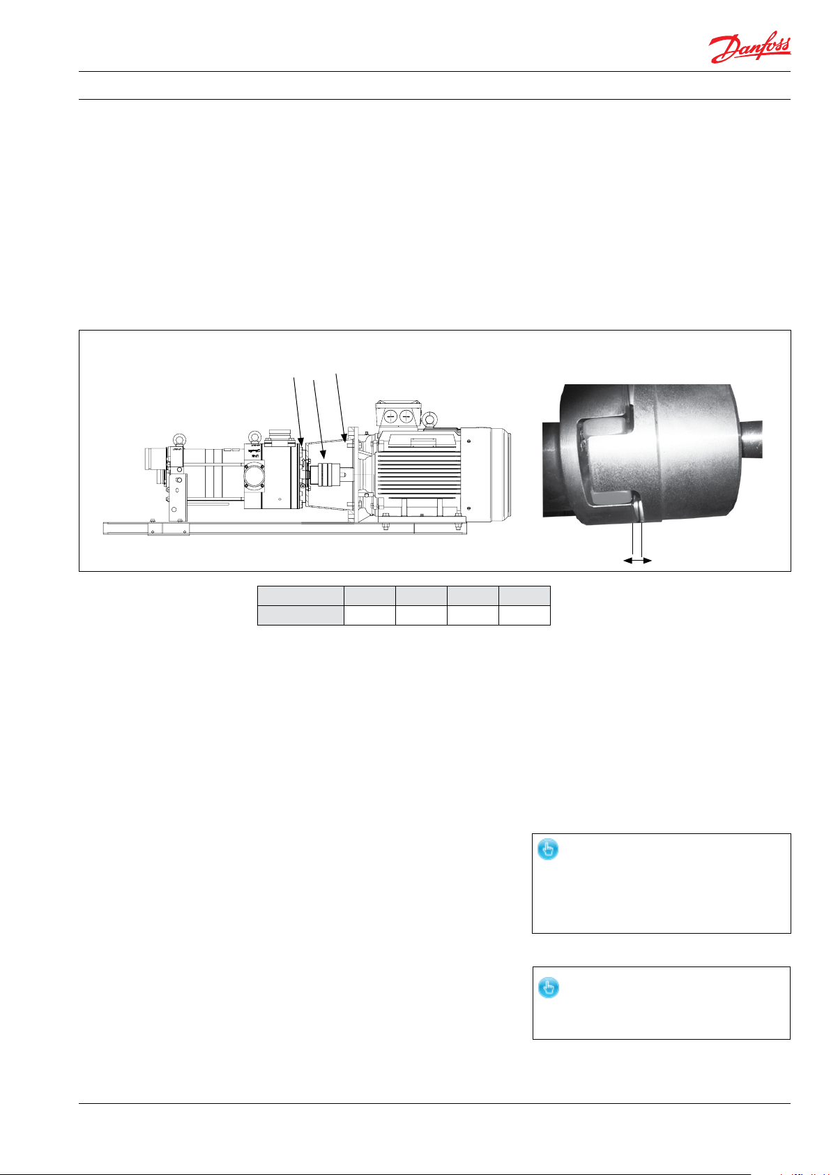
1: Bolts: torque 100 Nm
2: Screw: torque 40 Nm
3: Torque see table below
6. Adjust respectively, verify the measure
ment, and secure both couplings with the
right torques on the locking screws (see
coupling operation & mounting instruc
tion).
7. Mount the elastic gear ring and mount
the bell housing/iSave on the motor.
After mounting it must be possible to
move the elastic gear ring 3-5 mm (0.12 -
0.2 inch) axial “C”. The check can be done
through the inspection hole of bell
housing. Secure flange bolts with the
right torque.
2 3 1
If alternative mounting is desired, please contact
Danfoss High Pressure Pumps.
Choose proper tolerances to ensure an easy
mounting of the elastic coupling without use of
tools.
Please take care to observe the recommended
length tolerances of the chosen coupling, as an
axial force on the pump will damage the pump.
(“C” can be found on the drawing below).
Thread size M5 M6 M8 M10
Torque (Nm) 2 4.8 10 17
Details on how to install iSave 50/70 on Danfoss
vertical and horizontal frame can be found in the
Service guide 180R9387.
4.5 Storage
When each iSave is tested before shipment in
demineralized water. When tested the iSave is
emptied and “plugged”, this will prevent frost
damages.
The storage temperature is is:
-40 °C to +70 °C (-40°F to 158 °F) –
provided that the iSave is drained of fluid and
stored “plugged”.
Frost protection is required if the iSave is not
completely drained of fluids at temperatures
below 1 °C .
Storage of iSave that have been in operation:
For shorter periods of storage flush the iSave
with permeate and store.
For long term storage (more than 2 months)
Danfoss recommends servicing the product
and clean any biological growth of the
surfaces. Store the pump dry witout water
inside.
3-5 mm
Danfoss recommends using DOWFROST from
DOW Chemical Company or Chillsafe mono
propylene glycol from Arco Chemical Company.
For further information on anti-freeze media,
please contact Danfoss High Pressure Pumps.
The iSave is NOT delivered frost-protected
from the factory.
Only remove caps from the openings of the
iSave at the time of installation.
4.6 Outdoor Storage
For outdoor storage cover the iSave (set) with
waterproof material.
180R9357 | AQ265943679828en-001001 IOM iSave 50 - 70 | 02.2022
9
Page 10
Operating guide | iSave 50 - 70
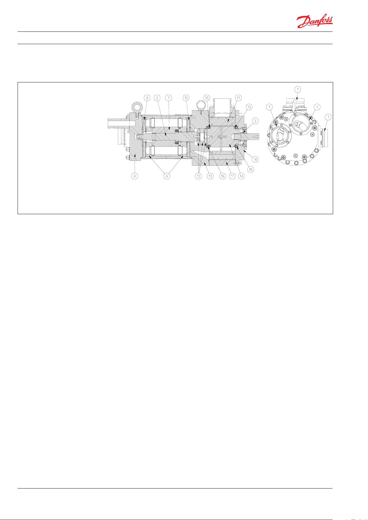
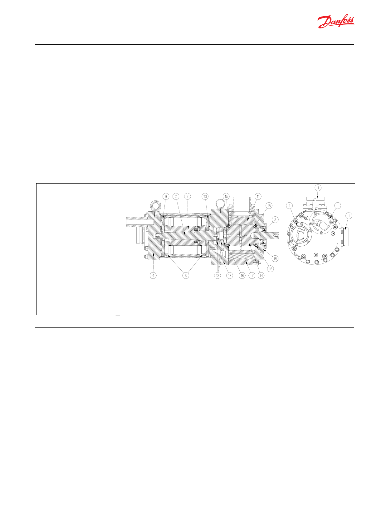
5. Technical data and
design review
1: 3” Victaulic connections
2: Shaft
3: Low pressure shaft seal
4: Port flange
6: Valve plate
7: Cylinder drum
9: Port plate (brine)
10: Port pllate (sea water)
11: Vanes
12: Coupling
13: Intermediate flange
14: Rotor
15: Rotor element
16: Sealing plate
17: Stator
18: Motor end flange
5.1 Design details
5.2 Sound level of the iSave
The A-weighted sound pressure level @ 1m,
L
is for the iSave including the iSave motor.
PA, 1M
Measurement are according to EN ISO
3744:2010. The test is made under following
conditions:
1. iSave and electrical motor mounted on
Danfoss base plate.
2. Baseplate is isolated from concrete ground
by rubber vibration dampers.
3. Flexible hoses are used on high pressure
and low pressure sides of the iSave.
4. Rotation speed is max. rpm
5. System pressure max. allowable working
pressure and a booster pressure of 3 barg.
Influences
Since the iSave is mounted on a base plate and
connected to the electromotor by a bell housing,
the noise level can only be determined for the
complete unit (system).
It is therefore important that the iSave unit is
mounted correctly on a frame with dampers
to minimise vibrations and noise.
Alternativamente, emplee acoplamientos Victaulic®
flexibles en la tubería rígida.
The noise level is influenced by:
• The speed of the iSave. High speed creates
more noise than low speed.
• Rigid mounting of the iSave baseplate
generates more noise than flexible
mounting
• Pipe mounting directly to the iSave
increases the noise level compared to
flexible hoses.
• Higher pressure provides higher sound
level.
5.3 Materials
All critical parts of the iSave are made of
super-duplex 1.4410/UN S32750/1.4462/
UN S32205/S31803 or the like.
Non-critical parts that are not in contact with sea
water are made of AISI 316.
The shaft to the electrical motor is sealed by
a standardised mechanical seal.
It is also strongly recommended to use highpressure flexible hoses between the hard piping
in the RO plant and the iSave.
See “Hose assembly and installation” 180R9084 in chapter10.5 and Guide line Pipe
connections 180R9367.
Alternative use multiple flexible Victaulic®
couplings on the hard piping.
10
180R9357 | AQ265943679828en-001001 IOM iSave 50 - 70 | 02.2022
Page 11
Operating guide | iSave 50 - 70
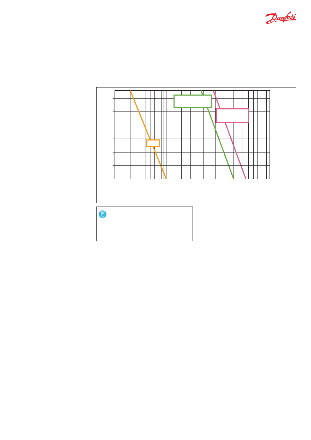
5.4 Temperature and corrosion
The chart below illustrates the corrosive
resistance of different types of stainless steel
related to NaCl concentration and temperature.
º
80
C
Duplex
70
60
50
316L
40
30
20
100
1000
160 1600
Depending on the NaCl concentration, the fluid
temperature must be between:
+2 °C y 50 °C (35,6 °F y 122°F).
Super Duplex
10 000
16000
100 000
160000
CI
ppm
NaCI
ppm
-
In order to minimise the risk of crevice
corrosion, always flush the iSave
according to the specified start/stop
procedure.
5.5 Dimensions and weights
For dimensions and weights please refer to the
iSave datasheet. See appendix 10.1
5.6 Electrical motor data
See datasheet in appendix 10.1 and “Operating
and Maintenance instructions, electric motor” in
appendix 10.7
5.7 How does the iSave work?
Figure 5.1 shows a section view of the iSave.
The iSave consists of a rotating isobargic
pressure exchanger and a positive
displacement pump, also called booster
pump. The rotation speed of the pressure
exchanger and the pump is exactly the
same, as they are driven by the same electric
motor.
180R9357 | AQ265943679828en-001001 IOM iSave 50 - 70 | 02.2022
11
Page 12
Operating guide | iSave 50 - 70
5.8 Seawater quality
5.81 Pre-filtration
It is important that the incoming water is filtered
properly to assure optimum service life of the
iSave. A true graded density melt-blown depth
filter cartridge rated at 3 μm is therefore
recommended. Poor pre-filtration of the feed
water will result in reduced service life of the
iSave.
The iSave may request a different pre-filter of the
seawater than the HP pump and other
omponents in the RO system.
It is important to use a proper filter housing that
allows a good seal between housing and filter
cartridge. If there is a high risk of water by-pass it
is recommended to use a second stage filter
solution.
As the various filters on the market differ greatly,
Danfoss High Pressure Pumps recommends using
cartridges with consistent, reliable performance
and high efficiency, in which fibres are blown
continuously onto a central support core.
Danfoss High Pressure Pumps does not
recommend cartridges requiring any type of
binders or resins.
Filters can be purchased from Danfoss High
Pressure Pumps.
5.8.3 Chemicals
The iSave can be flushed with biocide like the
membranes. The biocide must be compatible
with the materials used in the iSave.
iSave material can be found in the parts list,
appendix 10.6.
5.8.4 Initial start up and flushing
Prior to the initial start-up, all piping associated
with the iSave unit should be thoroughly flushed
to assure that no impurities enter the iSave.
Inadequate pre-flushing will strongly affect the
life of the iSave and may lead to its eventual
breakdown.
It is essential that the water used for the final
pre-flush is pre-filtered to a level described in
chapter 5.8
It is recommended to disconnect all connections
to the iSave and to thoroughly flush the piping
before the iSave is connected to the inlet and
outlet connections.It is recommended to install
temporary basket strainers at both inlets to
the iSave during the initial start-up and
commissioning.
Strainers do not eliminate the need for
thoroughly pipe flushing before commissioning.
Also see “Instruction for start and stop of
the SWRO with iSave unit” - 180R9213 in
appendix 10.2.
5.9 Initial start up and settings of safety
equipment
The system designer is responsible to design the
equipment according to the local regulations where
the equipment is running. According to PED
2014/68/ EU a risk assessment must be made to
identify and evaluate hazards which apply to his
equipment on account of pressure.
For more information on the importance of
proper filtration, please consult our
publication “Filtration”,
AI317041322125en-000201 which also will
provide you with an explanation of filtration
definitions and guidance on how to select the
right filter.
5.8.2 A ir bubbles
Large bubbles in a pressurised RO system can
result in damage to piping and equipment. All air
must be bleed from both the LP and HP before
the RO system is pressurised. Special
consideration should also be given to air bubbles
in feed flow, continuously fed into the HP pump
and iSave.
Where under reasonable foreseeable conditions, the
allowable limits could be exceeded, the pressure
equipment must be fitted with, or provision made
for fitting of a suitable protective device.
Dischage pressure on the pump is generated only
by the restriction in the pipelines, valves and
membranes.
The pump can build up pressure that will exceed
the mechanical strength of the membrane
vessels, pipes and other accessories.
The pressure rise can be fast and may exceed the
response time for electrical safety equipment,
like pressure switch and control loop.
12
180R9357 | AQ265943679828en-001001 IOM iSave 50 - 70 | 02.2022
Page 13
Operating guide | iSave 50 - 70
To prevent such over-pressurisation, appropriate relief valves should be used and procedures should be implemented to safeguard
the HP and LP sides of the iSave and/or the
RO system.
5.12 High pressure remains after shutdown
The HP line of the RO system equipped with an iSave
can remain pressurised for a long time after
shutdown. Pressure decreases as water slowly leaks
through the iSave. If more rapid system
depressurisation is required, the system should be
bled through a suitable valve on the HP concentrate
line.
trado HP.
5.10 Flushing
RO membranes require periodic flushing to
limit biological fouling.
There are two types of flushing: feed water
(Seawater) flush and fresh water (Permeate)
flush.
Regardless of the flush water used, the water
must be pre-filtered to the level described
in chapter 5.8. All parts of the iSave must be
flushed, i.e. LP- and HP flow channels.
Follow the guide line 180R9213 “Start and stop of
the SWRO with iSave in appendix 10.2.
It is required to flush with permeate:
• After chemical treatment
• For stop more than 1 day the iSave must be
rotated during permeate flush
• Before long time shut down
It is required to flush with fresh sea water prior to
every shut down.
Special attention should be given to the
pressure in the HP line (7) as the iSave may
start to cavitate when it runs at high speed
and the pressure in the P line (7) drops below 2
bargs. This can be avoided by reducing the
speed of the iSave and keeping the pressurein
the HP line at the minimum of 2 barg.
At this low pressure the iSave may only
run for a maximum of 10 minutes.
Always check the pressure in the high-pressure
lines before making service in the HP lines or
pressurised equipment.
5.13 Over-pressurisation caused by low
pressure isolation
If the low-pressure side of the iSave is blocked
and the iSave is exposed to high-pressure, there
is a risk that the iSave or the LP piping could be
damaged by over-pressurisation.
To prevent such over-pressurisation, appropriate
relief valves should be used and procedures should
be implemented to assure that the HP of the iSave is
depressurised prior to the isolation of the LP side..
5.14 Over-pressurisation caused by the
high-pressure pump.
Discharge pressure on the pump is generated
only by the restriction in the pipelines, valves
and membranes. The pump can build up
pressure that will exceed the mechanical
strength of the membrane vessels, pipes
and other accessories. The pressure rise can be
fast and may exceed the response time for
electrical safety equipment, like pressure
switch and control loop.
Failing to flush the iSave with fresh water before
extended shutdowns may result in extensive
biological growth and cause corrosion in the
iSave and other equipment in the RO system.
5.11 CIP or membrane cleaning
The purpose of membrane cleaning is to reduce
scaling and fouling in the membranes. For optimal
performance specific chemicals are required,
depending on the cause of the pollution. After
chemical treatment the system must be
flushed with permeate.
The flush water coming out of the membranes may
consist of a large amount of suspended inorganic
particles. It is important to assure that hese particles
must not enter the iSave as the waste product of
flushing exceed the iSave filtration.
Also see instruction “Membrane cleaning of
RO system with iSave unit” in appendix 10.3.
180R9357 | AQ265943679828en-001001 IOM iSave 50 - 70 | 02.2022
To prevent such over-pressurisation, appropriate
relief valves should be used and procedures should
be implemented to assure that the HP of
the iSave is protected against excess pressure.
5.15 Explanation of P&ID set-up
See data sheet in appendix 10.1.
13
Page 14
Operating guide | iSave 50 - 70
!
6. On-site installation 6.1 Design details
For safety instruction see chapter 3.
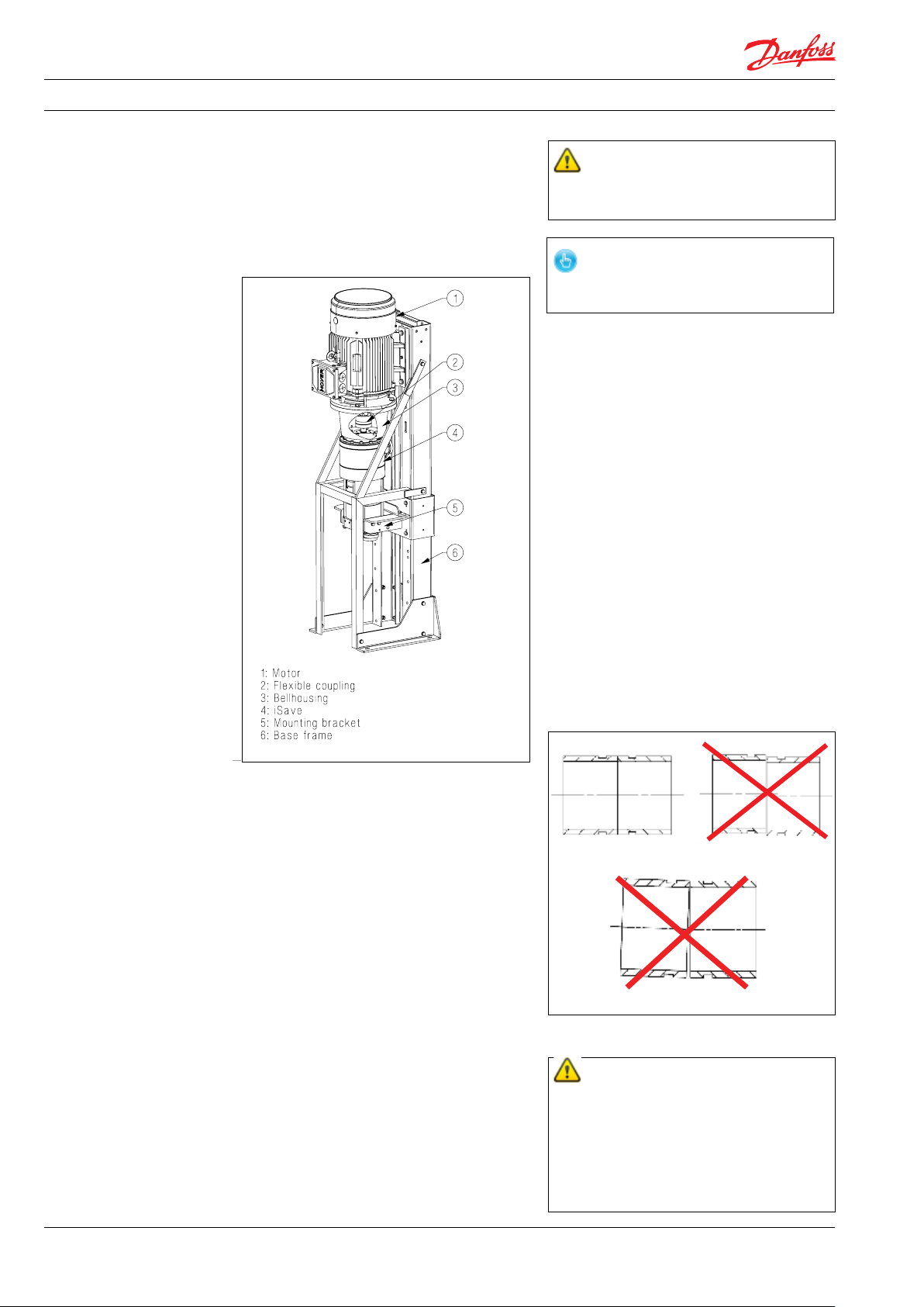
6.2 Installation and alignment
The figure below illustrates the major iSave
components.
An unlocked bolt can result in personal injury
and/or damage to the iSave
Misalignment of the base frame to the iSave may
cause stress and/or damage.
6.3 Orientation
The iSave can be mounted horizontally and
vertically.
When mounted vertically, the electric motor
must be placed above the iSave.
6.4 Piping and joints
Piping material and schedule is of high
importance. The strength of the Victaulic®
connections is influenced by the material used
for both the Victaulic® clamps and the hard
piping.
The hard piping and connections used must
be of proper design and must be installed in
accordance with the manufacturer’s
recommendations.
Hard piping to the iSave must be properly
aligned to avoid stress on the iSave port
connections.
Pipe connection must be aligned as
shown in the figures next page. Don’t use the
iSave as a strain for hard piping.
The iSave is connected to the electric motor
by the bell housing and a flexible coupling.
If not using Danfoss base frame both the
iSave and the motor must be supported
without applying stress/load to the bell
Ccrrect piping alignment Incorrect piping alignment
housing.
Danfoss provides the iSave with a base
frame and support brackets. Although the
base frame is of a sturdy design, it can flex
or bend when it is bolted to the foundation.
The base frame thus requires a solid
foundation such as concrete or rigid steel
frame. The base frame itself must be aligned
to avoid bending caused by bolting to an
uneven foundation.
Incorrect piping alignment
A rigid foundation for the iSave assembly is
important, and must fulfil Eurocode 2:
EN1992-1-1, and the iSave assembly must
be bolted to the foundation with M12 bolts.
The bolts used must be of proper design
and must be installed in accordance with
bolt manufacturer’s recommendations.
To reduce noise it is recommended to use
resilient mounts between the baseplate and
The hard piping and connections used must
be of proper design and must be installed in
accordance with the manufacturer’s recom-
mendations.
the foundation. Make sure that the bolts are
properly locked and will stay locked over time.
A failure to comply with this will or may result
in personal injury and/or damage the iSave.
14
180R9357 | AQ265943679828en-001001 IOM iSave 50 - 70 | 02.2022
Page 15
Operating guide | iSave 50 - 70
Misalignment of the hard pipes may place
stress on the iSave port connections and may
damage the iSave.
6.5 Mounting of coupling
The figure below illustrates how to mount the
flexible coupling between the iSave and to
connect it to the electric motor..
100 NM ± 10 NM
Min. 3 -5 mm air space
A
PUMP
Type iSave 50 ERD
Code no. 180FXXXX
Serial no. XXXXXX02-XXX
MADE IN DENMARK
Danfoss A/S, 6430 Nordborg, Denmark
When connecting to the power supply, check the
direction of rotation. The rotation can only be
checked with water connected and iSave
bleeded. This can be made by:
1. Looking at the fan in the end of the electric
motor.
2. Removing the plug in the bell housing and
watch the rotation of coupling.
3. Before assembling the iSave on the electric
motor, check the rotation of the shaft on the
electric motor.
C
B
A: Flexible coupling
40 NM ± 4 NM
B: Bell housing
C: Motor shaft
Any axial and radial load on the shaft must be
avoided.
6.6 Accessibility
With respect to the service and replacement
of the complete iSave unit, it is recommended to
maintain sufficient space around the unit.
The space must be sufficient enough to allow for
safe lifting of the equipment, with no risk for
personal injury and/or damage to the iSave.
6.7 Drives
6.7.1 Electric motor
The iSave must only be driven by an electric
motor.
Special attention has to be on NON
PROTECTED - FREE ROTATING shaft on
the electric motor. Ignorance will or
could result in personal injury.
Running the iSave in the wrong direction for
more than a few minutes can cause unintended wear on the iSave. If the electric
motor is running at a lower speed, extra care
must be taken to ensure that the electric
motor is NOT overheated. External cooling
may be necessary.
6.7.3 Starting torque for the iSave
Because of the inertia and stick-slip friction of the
iSave internal parts, the torque may exceed the
maximum allowable operation torque for the
iSave when the speed is ramped up from zero to
maximum.
It is required to use a VFD. See Danfoss guide line
180R9372 “APP pumps and iSave overload
protection”.
Using anything other than an electric motor
can lead to an irreparable fracture of the
iSave’s internal parts.
6.7.2 Speed control
The rotation speed on the electric motor can
be controlled by a VFD. The VFD must be able to
operate at constant torque over the whole range
of speed. The direction of rotation can be seen
on the identification label.
180R9357 | AQ265943679828en-001001 IOM iSave 50 - 70 | 02.2022
15
Page 16
Operating guide | iSave 50 - 70
7. Commissioning,
start-up and shutdown
6.7.4 Torque overload protection on the
iSave
The electric motor and iSave must always be
protected against overload.
As continuously operation the maximum
torque on the iSave must be monitored.
The electric motor must be shut off if the
maximum torque of the iSave exceeds the
defined limit.
If more electric motors are powered by the
same VFD, each electric motor must be
equipped with “torque limit equipment” to
protect the iSave against overload.
Below are examples of equipment which
can measure the load on the electric motor
or limit the torque on the iSave.
7.1 Safety regulations
The operator ensures that all inspection and
installation work is performed by authorised,
qualified specialized personnel who are
thoroughly familiar with the manual..
• Before starting up the iSave and the
high-pressure pump, make sure that the
following requirements are met:
• The iSave has been properly connected to
the electric power supply and is quipped
with all protection devices in accordance
with EN 60204-1
• Check that all motor protections are
properly set.
• All safety equipment, auxiliary equipment
and connection required are properly
connected and operational.
• Check all bolts in all connections and in the
foundation of the iSave and the pumps.
7.2 Support
Danfoss A/S offers commissioning and service at
system manufacturer’s location.
Rated quotes are offered upon request.
1. VFD with integrated current monitoring
relays.
2. External current monitoring relays suitablefor VFD control.
The electric motor and iSave must always be
protected against overload.
See Danfoss guide line 180R9372 “APP pumps
and iSave overload protection” in the appendix
10.4.
If torque exceeds the maximum operation
torque, it may lead to an irreparable fracture of
the iSave’s internal parts.
7.3 Commissioning
Before starting up the iSave and the highpressure pump, make sure the following
requirements are met:
• All pipes are flushed, free from debris and
full of water.
• The iSave has been bled and is full of
water.
• At pressure lower that 10 barg, check the
system for leakage.
Slowly raise the pressure in the system and set
all pressure switches to the correct limit and
continually check all connections.
• If pressure relief valve is present, set
pressure relief valve on both low and
high-pressure at the maximum system
pressure.
• Check high-pressure hoses for proper
assembly and inspect for external leakage
for all connections.
• At low pressure, start the iSave and check
direction of rotation.
• “Start and stop procedure” Guide line
180R9213. - appendix 10.2.
16
180R9357 | AQ265943679828en-001001 IOM iSave 50 - 70 | 02.2022
Page 17
Operating guide | iSave 50 - 70
8. Service/Maintenance 8.1 Safety regulations
The operator ensures that all maintenance,
inspection and installation work is performed
by authorised, qualified specialist personnel
who are thoroughly familiar with the manual.
Before intervening in the iSave/system:
• The power must be shut off and the main
switch must be locked.
• The pressure in the high-pressure lines
must be drained to the low-pressure side.
• The water in all connected pipes must be
drained.
Always use suitable safety and lifting equipment when handling the iSave, and follow the
instructions in chapter 4.3.
• Assure correct settings of safety equipment before start-up.
• When the system is re-started after
service and maintenance follow the
instruction in chapter 8 and in “Start and
stop procedures” in guide line 180R9213
in appendix 10.2.
Three months after commissioning:
1. Re-check bolts in the foundation and the
base plate of the iSave and tighten the
bolts to specified torque if necessary.
2. Re-check alignment of the iSave base
plate and iSave.
3. Visually inspect all pipe connections/
couplings for external leakage.
4. Re-check bolts in all pipe connections/
couplings and tighten the bolts to
specified torque if necessary.
1. Replace filters if necessary.
2. Clean the filter housing and install the new
filter. Make sure no debris enters the
system.
3. Audibly inspect the iSave assembly. If there
is irregular sounds or vibration inspect the
internal parts of the iSave and replace if
necessary.
Half year:
1.
For vertical mounted electric motor
lubricate motor bearings.
8.2 Support
Danfoss A/S offers commissioning and service
at the system manufacturer’s location.
Tates/quotes are offered upon request.
8.3 Maintenance schedule
The schedule of preventive maintenance below
will help ensure that the iSave provides years of
trouble-free performance.
One day after commissioning:
1. Re-check bolts in the foundation and the
base plate of the iSave and tighten the
bolts to specified torque if necessary.
2. Visually inspect all pipe connections/
couplings for external leakage.
3. Re-check bolts in all pipe connections/
couplings and tighten the bolts to
specified torque if necessary.
1. Replace filters if necessary.
2. Clean the filter housing and reinstall
filters. Make sure no debris enters the
system.
Annually:
1. Re-check bolts in the foundation and the
baseplate of the iSave and tighten the
bolts to specified torque if necessary.
2. Re-check alignment of iSave base plate
and iSave.
3. Visually inspect all pipe connections/
couplings for external leakage.
4. Re-check bolts in all pipe connections/
couplings and tighten the bolts to
specified torque if necessary.
1. Replace filters if necessary.
2. Clean the filter housing and nstall the new
filter. Make sure no debris enters the
system.
3. Visually inspect iSave coupling and
replace if necessary.
4. Audibly inspect the iSave assembly. If
there is irregular sounds or vibrations
inspect the internals parts of the iSave
and replace if necessary.
5. Check power consumption. If there are
irregular parts of the iSave and replace if
necessary.
6. Lubricate motor bearings.
180R9357 | AQ265943679828en-001001 IOM iSave 50 - 70 | 02.2022
17
Page 18
Operating guide | iSave 50 - 70
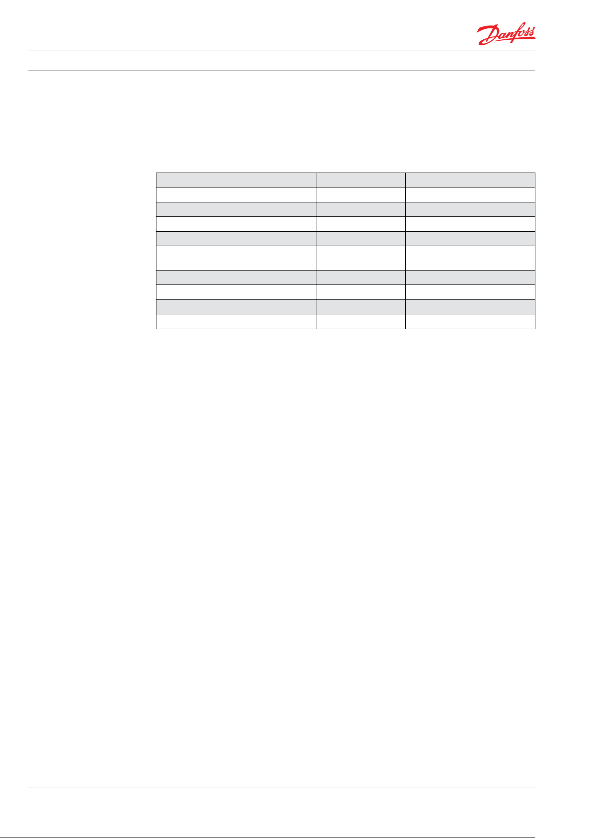
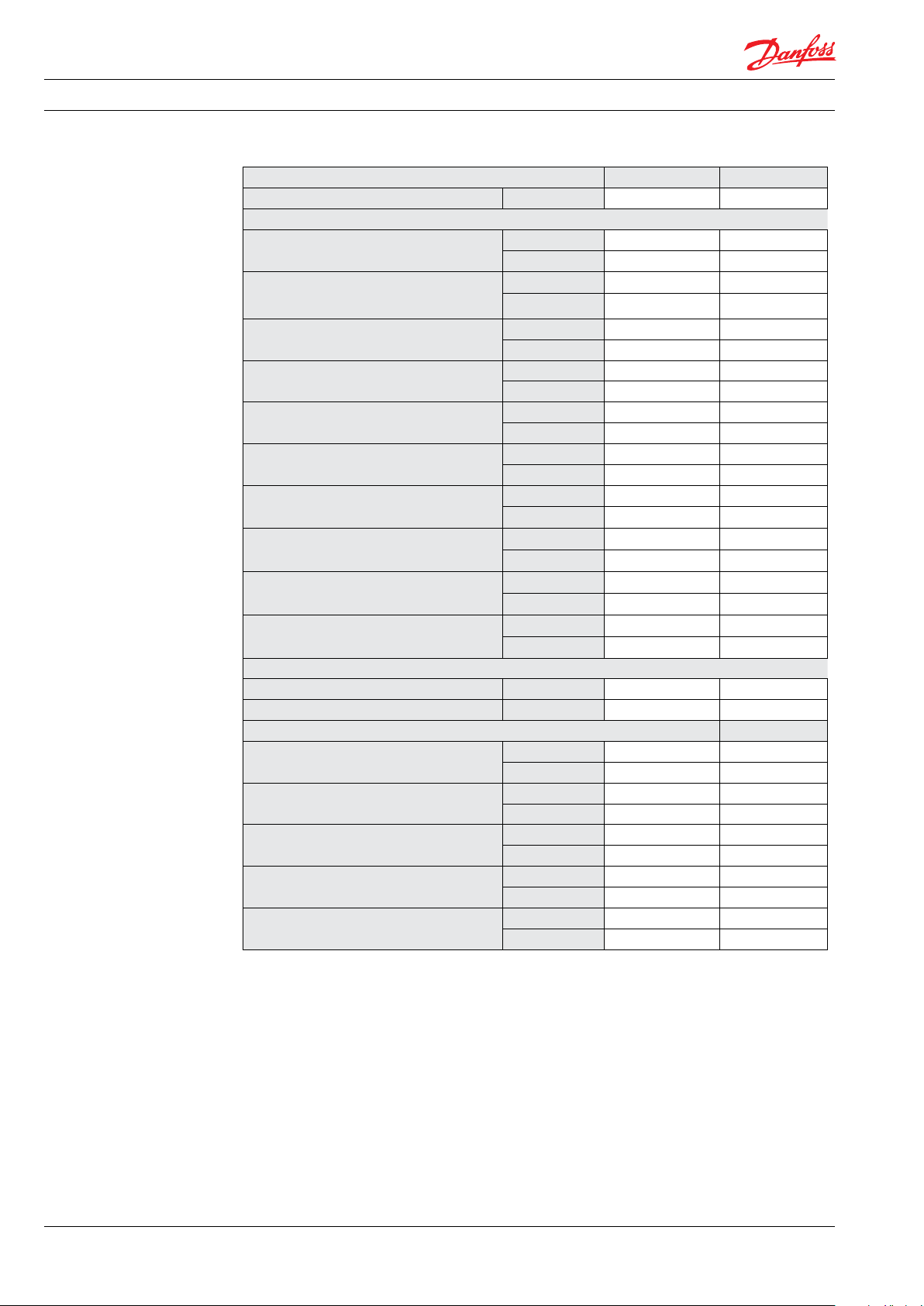
8.4 Recommended service intervals on
internal parts
Se below table.
For detailed information on parts see Service
guide 180R9392 Parts list.
Description Service interval Service interval (2nd, 3rd)
Tool kit
Screw and seal kit 32.000 hours 26.000 hours
Shaft seal kit 32.000 hours 26.000 hours
Coupling kit 56.000 hours 56.000 hours
Port plate kit (PE), iSave 50
32.000 hours 26.000 hours
Port plate kit (PE), iSave 70 32.000 hours 26.000 hours
Vane kit (8 pcs)
Valve kit, Pressure exchanger 32.000 hours 26.000 hours
Rotor element and sealing plates kt 32.000 hours 26.000 hours
8.5 Lubrication of bearings in electric
motor
Motors with a re-greasing system must be
lubricated with high quality lithium complex
grease, NLGI grade 2 or 3 with a temperature
range between -40 °C to 150 °C.
For electric motors in vertical mount; grease
every 6 months.
For electric motor in horizontal mount;
grease every 12 months.
If the motor has increased vibrations or
sound check the bearings.
Follow manufacturer’s recommendations for
electric motor service and maintenance, see
appendix 10.7.
18
180R9357 | AQ265943679828en-001001 IOM iSave 50 - 70 | 02.2022
Page 19
Operating guide | iSave 50 - 70
9. Trouble-shooting 9.1 Safety regulations
Before intervening in the iSave/system:
The operator ensures that all inspection and
installation work is performed by authorised,
qualified specialist personnel who are
thoroughly familiar with the manual.
• The power must be shut off and the
starting device be locked.
• The pressure in the high-pressure lines
must be drained to lowpressure side.
• The water in all connected pipes must be
drained.
The numbers in () correspond to the preferred system design and P&ID (see data sheet)
Problem Possible cause Action
VFD cannot start the iSave at initial start-up VFD is not designed for constant torque
VFD cannot deliver sufficient start torque
Ramp-up settings in the VFD are not correct. VFD is tilting
Choose a VFD that is designed for constant
torque
Choose a VFD that is designed for sufficient
start torque. See guide line 180R9372
Set ramp-up parameters correct. See guide
line 180R9372
Valve (9) is closed Open valve (9)
Start the iSave only when the pressure in
the HP line is low
Clean or change membranes
Torque on iSave is too high during operation
Pressure in the HP line (5) is too high
Pressure difference from HP-out (5) to HPin (10) is too high
Debris in the booster pump or iSave Clean the system
Wear in the booster pump or iSave Repair or change the parts
Design of the basic plant does not fit the
performance of the iSave
Change design to fit the iSave performance
Permeate production is too low (17) Valves (6), (7), (8) or (16) are leaking Repair or change valve(s)
Internal leakage in iSave Repair iSave
HP pump flow (2) is too small Correct speed on the HP pump
Check the HP pump and repair if necessary
Pressure on the membranes (5) is too high
Fouling on the membranes Clean the membranes
Mixing in the iSave is too high Check flow on LP-in (12) and adjust flow
Flow out of the iSave is too low and causes
a recovery rate that is too high
Check speed on iSave and change if necessary
Booster pump in the iSave is worn out.
Perform service on the VP
Pressure on the membranes (5) is too low
Valves (6), (7), (8) or (16) are leaking Repair or change valve (s)
Internal leakage in iSave Repair iSave
Pressure on the membranes (5) is too low Incorrect speed on the HP pump
Check the HP pump and repair, if necessary
180R9357 | AQ265943679828en-001001 IOM iSave 50 - 70 | 02.2022
19
Page 20

Operating guide | iSave 50 - 70
20
180R9357 | AQ265943679828en-001001 IOM iSave 50 - 70 | 02.2022
Page 21
Appendices
Energy Recovery Device
iSave 50-70
Appendices - Installation, Operation
and Maintenance Manual
hpp.danfoss.com
Page 22

Operating guide | iSave 50 - 70
10. Appendices............................................................................21
10.1 Data sheet iSave 50-70 - (521B1378)) ....................................................23
10.2 Start and stop procedures (180R9213). ..................................................45
10.3 Membrane cleaning of the RO system with iSave unit (180R9214) . ......................51
10.4 APP pumps and iSave overload protection(180R9372)...................................57
10.5 Hose assembly and installation (180R9084) .............................................67
10.6 iSave part list 50-70 (521B1428) .........................................................75
10.7 Operating- and maintenance instruction, electric motor (180R9230).....................87
22
180R9357 | AQ265943679828en-001001 IOM iSave 50 - 70 | 02.2022
Page 23
Data sheet
iSave® Energy Recovery Device
iSave 50 / iSave 70
hpp.danfoss.com
Page 24

Data sheet | iSave 50 and iSave 70
Table of Contents Contents
1. General information....................................................................25
2. Benefits................................................................................25
3. Applications ...........................................................................25
4. Technical data .........................................................................26
4.1 iSave without motor ...................................................................26
4.2 iSave with IEC motor ...................................................................28
4.3 iSave with NEMA motor ................................................................29
5. Performance curves....................................................................30
5.1 Flow at different rpm...................................................................30
5.2 iSave 50 flow curves....................................................................30
5.3 iSave 70 flow curves....................................................................30
5.4 Torque curve for iSave 50 and iSave 70..................................................31
5.5 Mixing curve...........................................................................31
6. Temperature and corrosion.............................................................32
6.1 Operation..............................................................................32
7. Installation.............................................................................32
7.1 Operation and mounting...............................................................32
7.2 Horizontal mount . . . . . . . . . . . . . . . . . . . . . . . . . . . . . . . . . . . . . . . . . . . . . . . . . . . . . . . . . . . . . . . . . . . . . .32
7.3 Connection to inlet or discharge ports: .................................................33
7.4 Filtration...............................................................................33
7.5 N o ise ..................................................................................33
7.5 RO systems with an iSave...............................................................34
8. Dimensions and connections...........................................................36
8.1 iSave 50-70 without electric motor .....................................................36
8.2 iSave 50-70 with with IE3 motor 18.5 kW on base frame vertical_front mounted .........37
8.3 iSave 50-70 with with IE3 motor 18.5 kW on base frame vertical_back mounted..........38
8.4 iSave 50-70 with with IE3 motor 18.5 kW on base frame horizontal.......................39
8.4 iSave 50-70 with NEMA motor 30 HP on base frame vertical - front mounted .............40
8.5 iSave 50-70 with NEMA motor 30 HP on base frame vertical - back mounted .............41
8.5 iSave 50-70 with NEMA motor 30 HP on base frame horizontal ..........................42
9. Service.................................................................................43
9.1 Warranty...............................................................................43
9.2 Operational conditions of concern......................................................43
9.3 Maintenance...........................................................................43
9.4 Repair assistance .......................................................................43
10. Accessories ............................................................................43
11. Useful documents......................................................................43
24
180R9357 | AQ265943679828en-001001 IOM iSave 50 - 70 | 02.2022
Page 25
Data sheet | iSave 50 and iSave 70
1. General information Energy Recovery Devices (ERD) are used in
reverse osmosis (RO) systems to recycle the
energy held in discharged brine from the
membranes. Thus, iSave 50 and iSave 70 are
designed for use with low viscosity and corrosive
fluid such as sea water.
The Danfoss iSave Energy Recovery Devices all
consist of an isobaric pressure exchanger and a
positive displacement pump combined into one
compact unit. The high-pressure booster pump
is based on the vane pump principle enabling a
very light and compact design. The vane pumps
are fixed displacement pumps in which the flow
is proportional to the number of revolutions
(rpm) of the driving shaft – enabling flow control.
Speed control is made by a VFD. The iSave design
ensures lubrication of the moving parts by the
fluid itself.
1. 3” Victaulic connections
2. Shaft
3. Low pressure shaft seal
4. Port flange
6. Valve plate
7. Cylinder barrel
9. Port plate (brine)
10. Port plate (sea water)
11. Vane s
12. Coupling
13. Intermediate flange
14. Rotor
15. Rotor element
16. Sealing plate
17. Sta t or
18. Motor end flange
All parts included in the iSave 50 & 70 are
designed to provide long service life with a
constant high efficiency and minimum service
required.
Unlike a centrifugal pump, it produces a similar
flow at a given speed no matter what discharge
pressure.
2. Benefits • Corrossion resistance (all wetted parts are made
• Significant power savings and low specific
energy consumption (SEC)
• Simple and space-saving installation with
both pump and pressure exchanger in one
of high corrosion-resistant materials e.g. Super
Duplex or Duplex)
• Fewer components
unit
• Simple system design and monitoring
without requirement for high-pressure flow
meters
• Simple operation with design that prevents
overspin/overflushing
• Easy modular service
3. Applications
Danfoss iSave ERDs are built into a broad range
of RO desalination plant around the world.
Typical applications for iSave 50 - 70 will be:
• Containerized solutions for hotels and
resorts on islands as well as coastal regions
• Onboard systems for ships
• Offshore platforms for the oil and gas
industry
• Municipal and private waterworks
180R9357 | AQ265943679828en-001001 IOM iSave 50 - 70 | 02.2022
25
Page 26
Data sheet | iSave 50 and iSave 70
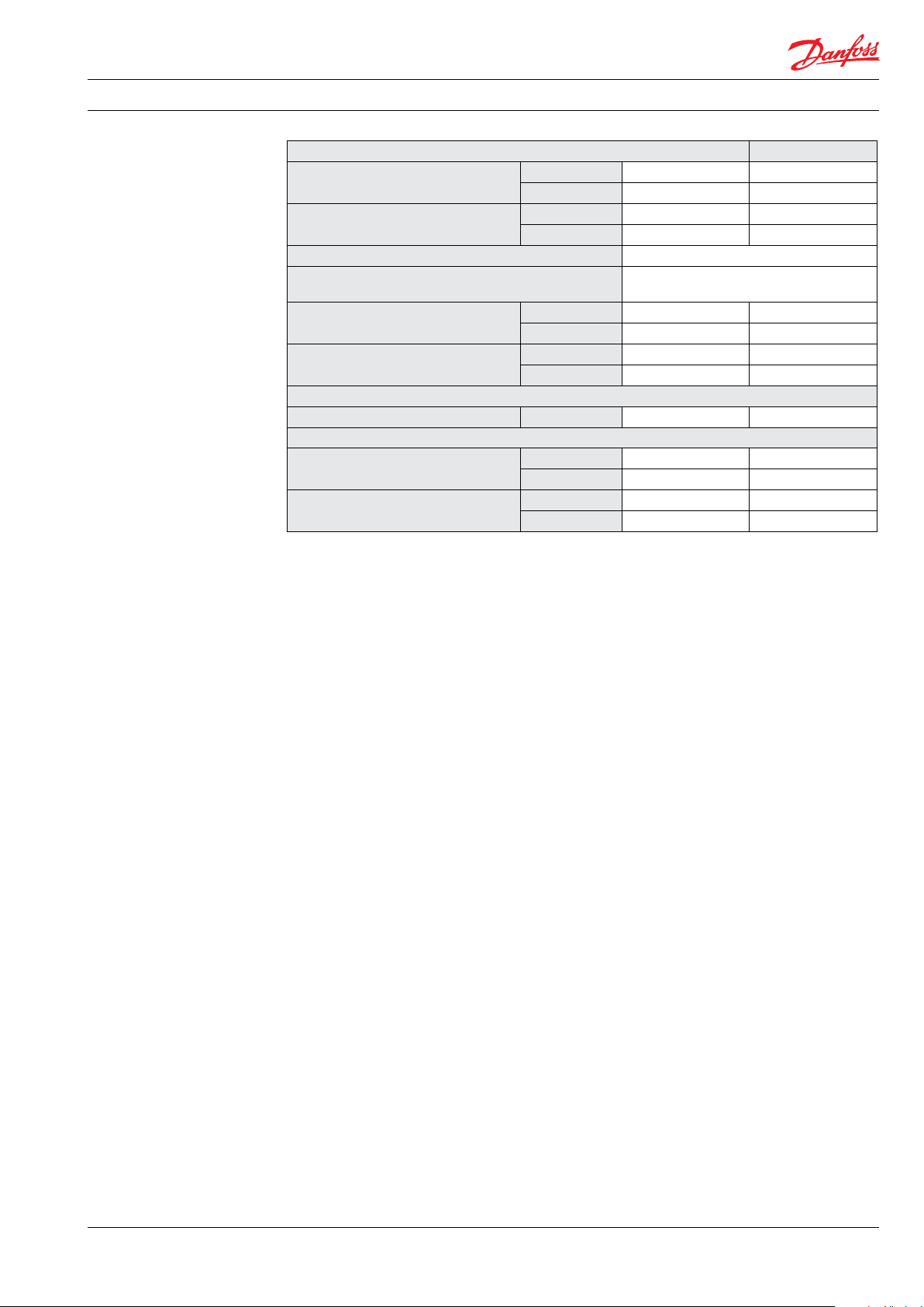
4. Technical data 4.1 iSave without motor
iSave size iSave 50 iSave 70
Code number 180F7020 180F7021
Pressure
Max. differential pressure (HP out - HP in)
Min. pressure HP out (min. allowable working
pressure)
Max. pressure HP out (Max. allowable working
pressure, MAWP)
Min. pressure on HP in,
intermittent
Max. pressure LP in (MAWP)
Max. pressure LP in, peak
Min. allowable working pressure LP in
Max. differential pressure (LP in - LP out)
Max. static test pressure (HP in and HP out)
Max. static test pressure (LP in and LP out)
Speed
Min. speed rpm 525 625
Max. speed rpm 650 875
Typical flow
Flow at min. speed, HP out
Flow at max. speed. HP out
Max. lubrication flow at 60 barg (871 psig)
Peak flow, LP in
Max. allowable working flow, LP in
1)
2) 3)
4)
10)
barg 5 5
psig 72 72
barg 40 40
psig 580 580
barg 83 83
psig 120 0 120 0
barg 2 2
psig 29 29
1)
barg 5 5
psig 72 72
barg 10 10
psig 145 145
barg 2 2
psig 29 29
barg 0.53 0.79
psig 7. 69 11.46
barg 108 108
psig 1566 1566
barg 13 13
psig 189 189
m³/h 42 50
gpm 184 220
m³/h 52 70
gpm 228 308
l/min 25 25
gpm 6.6 6.6
m³/h 120 120
gpm 528 528
7)
m³/h 57. 2 70
gpm 252 308
26
180R9357 | AQ265943679828en-001001 IOM iSave 50 - 70 | 02.2022
Page 27
Data sheet | iSave 50 and iSave 70
Technical specifications
Media temperature
Ambient temperature
Filtration requirements (nominal)
Salinity increase at membrane at 40% recovery rate at
balanced flow
Weight (dry)
Weight (operation with water)
Noise
Sound pressure level L
Torque data
Max. allowable working torque
Max. starting torque (stick/slip)
o
5)
6)
9)
C 2-35 2-35
o
F 36-95 36-95
o
C 0-50 0-50
o
F 32-122 32-122
3 micron melt-blown
2-3%
kg 164 164
lb 362 362
kg 172 172
lb 379 379
8)
PA
1 m
dB(A) 83 86
Nm 170 19 0
lbf-ft 12 5 140
Nm 18 0 180
lbf-ft 132 132
1)
Max. allowable working pressure of continous
operation. For lower and higher pressure, please
contact Danfoss.
2)
Typical pressure level at start-up and permeate
flush.
3)
Intermittent pressure is acceptable for less than 10
minutes within a period of 6 hours.
4)
Typical average flow at 60 barg and 3 barg
differential pressure
5)
Dependent on NaCI concentation.
6)
Please see section 7.4 filtration.
7)
Continuous operation: iSave can operate
continuously with up to 10% over flush with the
limitation that the flow rate at LP inlet shall not
exceed 70 m3/h.
8)
A-weighted sound pressure level at 1 m from the
pump unit surfaces (reference box) acc. to EN ISO
20361 section 6.2. The noise measurements are
performed acc. to EN ISO 3744:2010 on a motor-
pump-unit at max. pressure and rpm.
9)
Balanced flow: The mixing rate is defined at
balanced flow when HP-out is equal to LP-in.
10)
At system start-up: iSave can run for up to 10 min.
with 150% of max. rated flow at LP inlet. The time
where max. rated flow is exceeded should be kept
as short as possible to minimize wear.
180R9357 | AQ265943679828en-001001 IOM iSave 50 - 70 | 02.2022
27
Page 28
Data sheet | iSave 50 and iSave 70
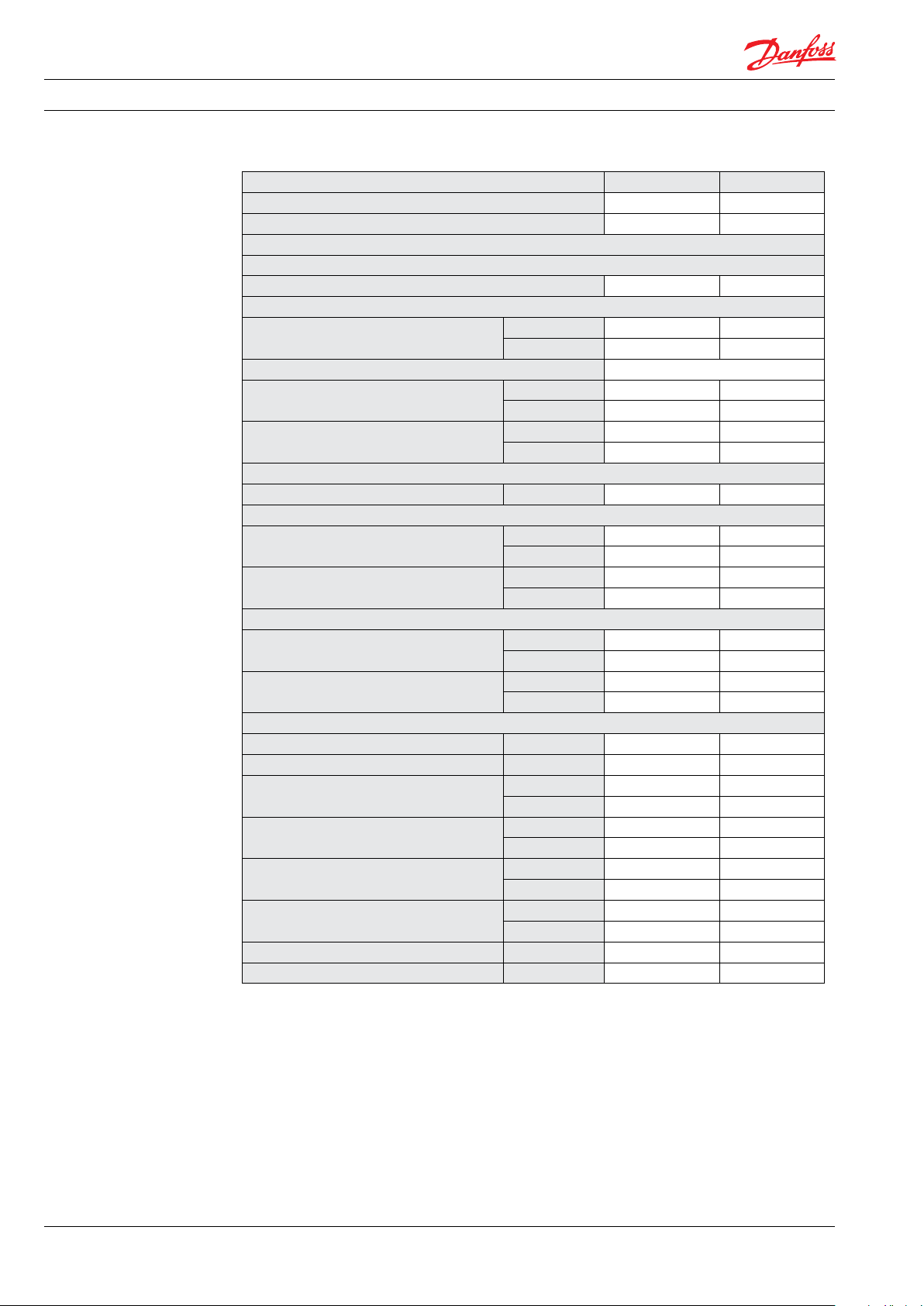
4.2 iSave with IEC motor
i
iSave size iSave 50 iSave 70
Code number (vertical) 180F7038 180F7040
Code number (horizontal) 180F7023 180F7025
Pressure, Speed, Flow, Temperature and Torwue are identical with 180F7020 and 180F7021
Efficiency
Efficiency at max. speed at 60 barg (871 psig) % 93.7 92.4
Technical specifications
Media temperature
Filtration requirements (nominal)
Weight (dry) vertical/horizontal
Weight (operation with water) vertical/
horizontal
Noise
Sound pressure level L
Footprint
Footprint (vertical position)
Footprint (horizontal position)
Torque data
Max. allowable working torque
Max. starting torque (stick/slip)
Motor data
Nominal speed rpm 985 985
Rated current at 400V A 37 37
Motor size
Frame size
Rated motor torque at nominal speed
Rated motor ambient temperature
Motor insulation Class B B
Motor degrees of protection IP 55 55
5)
°C 2-35 2-35
°F 36-95 36-95
6)
3 micron melt-blown
kg 441/463 441/463
lb 972/1021 972/1021
kg 470/471 470/471
lb 1036/1038 1036/1038
2)
PA
1 m
3)
dB(A) 83 86
m² 0.44 0.44
foot² 4.71 4.71
3)
m² 0.76 0.76
foot² 8.14 8.14
Nm 170 177
lbf-ft 125 130.5
Nm 180 180
lbf-ft 132 132
kW 18. 5 18.5
HP 30.0 30.0
IEC 200 L 200 L
Poles 6 6
Nm 177 177
lbf-ft 130.5 130.5
4)
°C 40 40
°F 104 104
28
2)
A-weighted sound pressure level at 1 m from the ERD
unit surfaces (reference box) acc. to EN ISO 20361
section 6.2. The noise measurement are performed
acc. to EN ISO 3744:2010 on an ERD with motor
(motor pump unit) from min. to max. pressure and
speed.
3
Area covered with recommended IE3 motor
configurations (excl. of space to service the ERD)
4)
For higher temperature, contact Danfoss.
5)
Dependent on NaCI concentation.
180R9357 | AQ265943679828en-001001 IOM iSave 50 - 70 | 02.2022
)
6)
Please see section 7.4 Filtration
7)
Typical efficiency for pressure exchanger, ..
booster pump, electrical motor and VFD at 3
barg differential pressure after a system has ...
been commissioned and run in.
Page 29

Data sheet | iSave 50 and iSave 70
4.3 iSave with NEMA motor
iSave size iSave 50 iSave 70
Code number (vertical) 180U0062 180U0064
Code number (horizontal) 180U0003 180U0005
Pressure, Speed, Flow, Temperatue and Torque are identical with 180F7020 180 F7021
Efficiency
Efficiency at max. speed at 60 barg (871 psig)
Technical specifications
Media temperature
Filtration requirements (nominal)
Weight (dry) vertical/horizontal
Weight (operation with water) vertical/
horizontal
Noise
Sound pressure level L
Footprint
Footprint (vertical position)
Footprint (horizontal position)
Torque data
Max. allowable working torque
Max. starting torque (stick/slip)
Motor data
Nominal speed rpm 118 0 118 0
Rated current at 400V A 36.2 36.2
Motor size
Frame size
Rated motor torque at nominal speed
Rated motor ambient temperature
Motor insulation Class B B
Motor degrees of protection IP 55 55
2)
A-weighted sound pressure level at 1 m from the ERD
unit surfaces (reference box) acc. to EN ISO 20361
section 6.2. The noise measurement are performed
acc. to EN ISO 3744:2010 on an ERD with motor
(motor pump unit) from min. to max. pressure and
speed.
3
Area covered with recommended IE3 motor
configurations (excl. of space to service the ERD)
4)
For higher temperature, contact Danfoss.
5)
Dependent on NaCI concentation.
7)
% 93.7 92.4
5
)
6)
°C 2-35 2-35
°F 36-95 36-95
3 micron melt-blown
kg 484/506 484/506
lb 10 67/1116 10 67/1116
kg 513/535 513/535
lb 1131/1179 1131/ 1179
2)
PA
1 m
3)
dB(A) 83 86
m² 0.44 0.44
foot² 4.71 4.71
3)
m² 0.76 0.76
foot² 8.14 8.14
Nm 170 177
lbf-ft 125 130.5
Nm 18 0 180
lbf-ft 132 132
kW 22.5 22.5
HP 30.0 30.0
NEMA 324/6T 324/6T
Poles 6 6
Nm 179 179
lbf-ft 132 132
4)
°C 40 40
°F 104 104
6)
Please see section 7.4 Filtration
7)
Typical efficiency for pressure exchanger, ..
booster pump, electrical motor and VFD at 3
barg differential pressure after a system has ...
been commissioned and run in.
)
180R9357 | AQ265943679828en-001001 IOM iSave 50 - 70 | 02.2022
29
Page 30

Data sheet | iSave 50 and iSave 70
0
10
20
30
40
50
60
525 650
Flow [GPM]
Flow [m
3
/h]
Motor speed [rpm]
Flow curve iSave50®
5 bar
2
bar
220
176
0,0
10,0
20,0
30,0
40,0
50,0
60,0
70,0
80,0
625 875
Flow [GPM]
Flow [m
3
/h]
Motor speed [rpm]
Flow curve iSave70®
2
bar
5 bar
220
308
5. Performance curves 5.1 Flow at different rpm
The diagram shows that the HP flow can be
changed by changing the rotation speed of the
iSave. The flow/rpm ratio is constant, the
required flow is obtainable by changing the
rotation speed to a required value.
5.2 iSave 50 flow curves
For accurate data and advise, please contact
Danfoss High Pressure Pumps.
The iSave is delivered with a 3.1 performance
certificate according to EN10204.
5.3 iSave 70 flow curves
30
180R9357 | AQ265943679828en-001001 IOM iSave 50 - 70 | 02.2022
Page 31

Data sheet | iSave 50 and iSave 70
5.4 Torque curve for iSave 50 and iSave 70
Below curve illustrates typical values.
Torque [Nm]
200
180
160
140
120
100
80
60
40
Torque on iSave50 and iSave70
Starting torque
delta-P: 5 bar
delta-P: 4 bar
delta-P: 3 bar
delta-P: 2 bar
delta-P: 1 bar
20
0
5.5 Mixing curve
525 645 765 875
Motor speed [rpm]
Volumetric mixing versus flushing
14,0
12,0
10,0
8,0
6,0
Volumetric mixing [%]
4,0
2,0
0,0
-10 -5 0 5 10
Flush ratio (larger than 0 means overflush) [%]
180R9357 | AQ265943679828en-001001 IOM iSave 50 - 70 | 02.2022
31
Page 32

Data sheet | iSave 50 and iSave 70
6. Temperature and
corrosion
6.1 Operation
The chart below illustrates the corrosive
resistance of different types of stainless steel
related to NaCl concentration and temperature.
All critical parts of the iSave is made of
Super Duplex 1.4410/UNS 32 750 or Duplex
1.4462/UNS 32803.
º
80
C
Duplex
70
60
50
316L
40
30
20
100
1000
160 1600
Always flush the iSave with fresh water at
operation stop in order to minimize the risk of
crevice corrosion.
Super Duplex
-
10 000
16000
100 000
160000
CI
ppm
NaCI
ppm
7. Installation
7.1 Operation and mounting 7.2 Horizontal mount
The iSave 50 and iSave 70 can be mounted
horizontally and vertically. When mounted
vertically, the electric motor must be placed at
the top of the iSave
The iSave is delivered with a standard port
orientation. The port orientation can be changed
by the customer by rotating the combined iSave
and bell housing around the center of the motor
shaft.
32
180R9357 | AQ265943679828en-001001 IOM iSave 50 - 70 | 02.2022
Page 33

Data sheet | iSave 50 and iSave 70
See example below on how to mount the pump
and connect it to an electrical motor.
A: Flexible coupling
B: Bell housing
C: Motor shaft
7.3 Connection to inlet or discharge ports:
• When using hard piping, it is important to
follow the Guideline 180R9367 - Pipe
connection.
• When using flexible hoses, it is recommened
to use Hose Whip Restraint. Also follow the
guideline 180R9084 - Right and Wrong Hose
assembly.
Note: Any axial and radial load on the shaft
must be avoided.
min. 3 - 5 mm air space
A B C
7.4 Filtration
High quality water extends the service life of the
whole system.
Water to the iSave must be filtered to 3 μm
nominal, using melt-blown depth filter with
good end sealings. Consult Danfoss for correct
choice of filter.
It is important with selection of a proper filter
and filter housing to ensure good cartridge end
sealing.
If there is a high risk of water by-pass it is
recommended to use a second stage filter
solution.
7.5 Noise
Since the iSave is mounted on a bell housing and
electric motor, the noise level should be
determined for a complete system. To minimize
vibrations and noise throughout the system, it is
improtant that a horizontal iSave unit is mounted
correctly on a frame with dampeners.
Rigid designs with metal pipes cause vibration
and noise. It is therefore recommended to use
high-pressure flexible hoses between the hard
piping in the RO-plant and the iSave or to used
multiple connections with Victaulic clamps
where possible.
The noise level is influenced by:
Speed:
• High rpm makes more fluid/structure-borne
pulsations/vibrations than low rpm due to
higher frequency.
180R9357 | AQ265943679828en-001001 IOM iSave 50 - 70 | 02.2022
As the various filters on the market differ greatly,
Danfoss High Pressure Pumps recommends
using cartridges with consistent, reliable
performance and high efficiency and where
fibres are blown continuously onto a central
support core. High Pressure Pumps does not
recommend cartridges requiring any type of
binders or resins.
Filters can be purchased from Danfoss
High Pressure Pumps. For more information on
the importance of proper filtration, please
consult our publication “Filtration” (code number
521B1009), which also will provide you with an
explanation of filtration definitions and a
guidance on how to select the right filter.
Pressure:
• High pressure makes more noise than low
pressure.
Mounting:
• Rigid mounting makes more noise than
flexible mounting due to structure-borne
vibrations.
Connections to iSave:
• Pipes connected directly to the iSave make
more noise than flexible hoses due to
structure-borne vibrations.
• Variable frequency drives (VFD):
Motors regulated by VFDs can increase noise
level if the VFD does not have the right
settings.
33
Page 34

Data sheet | iSave 50 and iSave 70
7.5 RO systems with an iSave
VFD
22
M
4
2
26
Media filter
A
B C
Filter
3 micron
nominel
PI
Fresh water
permeate flush
Filter
10 micron
absolut
PI
F
*
12
PI
PS
21
24
19
*
Second stage filter: If recommended housing des ign and cartridges are not used, a second stage filt er is required
3
LP in
PI
PS
F
1
HP out
11
M
4
26
iSave
HP in
M
VFD
23 23
25
18
25
18
HP out
HP in
M
VFD
VFD
5
PI
PS
13
14
PS
PI
6
7
20
F
22
Full flow
cleaning/CIP
1011
PI
15
17
Permeate
F
Flowmeter
8
9
16
28
CIP
27
Drain
Explanation of P&ID setup
D. Inlet flow control and mixing:
A. Inlet filter:
Place inlet filters on LP string in front of the
iSave (11). Please see Guide line 521B1009 on
Filtration.
To balance LP flow up against HP flow on the
iSave and control mixing, place a
flowmeter on low-pressure inlet (12) or low
pressure outlet (20) of the iSave.
If recommended housing design and
cartridges are not used, a second stage
filter is required, see above (*).
Thoroughly clean pipes and flush system
prior to start-up.
E. Outlet pressure control:
In order to control the inlet pressure needed a
back pressure valve (15) must be installed in
the common outlet pipe from the iSaves. The
valve should be designed to control flow.
B. Inlet pressure:
Must assure that iSave is running according to
specifications. Refer to iSave data sheet.
It is recommended to use a manual valve with
lock function or an automatic controlled
valve.
Required: Must assure min. pressure to avoid
cavitation.
Recommended: Must assure max. pressure to
avoid hydraulic and mechanical overload.
(13) used for iSave 21 and iSave 40.
(24) used for iSave 50 and iSave 70.
F. Variable speed and overload protection:
Install a VFD to control the speed of the iSave
and protect it against mechanical overload.
See instruction 180R9372 for guidance of VFD
settings.
C. Piping and hoses:
Dimension the piping to obtain minimum
G. LP discharge flow control:
See “E”.
pressure loss (large flow, minimum pipe
length, minimum number of bends/
connections and fittings to prevent pressure
loss and flow turbulence). Use flexible hoses
to minimize vibrations and noise. Please
consult the Danfoss Hoses and Hose Fittings
H. Air venting:
Install an air bleed valve (8) on the highest
point of the high-pressure piping to ensure
the air is purged from the system before
startup.
data sheet (521B0909 ) and Right and wrong
Hose assembly (180R9084) for guidance.
34
180R9357 | AQ265943679828en-001001 IOM iSave 50 - 70 | 02.2022
Page 35

Data sheet | iSave 50 and iSave 70
I. Pressure relief (high pressure):
The pressure relief valve (6) protects the whole
system against pressure overload and relieves
the water if the pressure exceeds the maximum set pressure. If the high-pressure pump
is a positive displacement pump, the pump
can built up a very high pressure that will
exceed mechanical strength of the membrane
housing, pipes and other accessories. When
using Danfoss APP pumps with Danfoss VCM
check valves, it is recommended to place a
pressure relief valve or pressure safety valve as
illustrated. In case the Danfoss check valves
are not used, the valve must be placed
between pump and check valve (See
180R9371, Design Guide Pressure saftey valve
in seawater RO sytem for more details).
J. Pressure relief (low pressure):
The pressure relief valve or pressure safety
valve (19) protects the low-pressure pipes
against pressure overload and relieves the
water if the pressure exceeds the maximum
allowable pressure.
For a more eleborate description of the P&ID
setup, please consult the Danfoss Design Guide
Piping & Instrumentation Diagram (P&ID)
(180R9370) or contact Danfoss.
The iSave 50 and iSave 70 can be mounted in
parallel. For more information, please see
“Design Guide Parallel-coupled APP and iSave”
-180R9354 or contact Danfoss.
180R9357 | AQ265943679828en-001001 IOM iSave 50 - 70 | 02.2022
35
Page 36

Data sheet | iSave 50 and iSave 70
8. Dimensions and
connections
8.1 iSave 50-70
without electric motor
36
180R9357 | AQ265943679828en-001001 IOM iSave 50 - 70 | 02.2022
Page 37

Data sheet | iSave 50 and iSave 70
8.2 iSave 50-70 with with IE3 motor 18.5 kW
on base frame vertical_front mounted
180R9357 | AQ265943679828en-001001 IOM iSave 50 - 70 | 02.2022
37
Page 38

Data sheet | iSave 50 and iSave 70
8.3 iSave 50-70 with with IE3 motor 18.5 kW
on base frame vertical_back mounted
38
180R9357 | AQ265943679828en-001001 IOM iSave 50 - 70 | 02.2022
Page 39

Data sheet | iSave 50 and iSave 70
8.4 iSave 50-70
with with IE3 motor 18.5 kW
on base frame horizontal
180R9357 | AQ265943679828en-001001 IOM iSave 50 - 70 | 02.2022
39
Page 40

Data sheet | iSave 50 and iSave 70
8.4 iSave 50-70 with NEMA motor 30 HP
on base frame vertical - front mounted
180R9357 | AQ265943679828en-001001 IOM iSave 50 - 70 | 02.2022
40
Page 41

Data sheet | iSave 50 and iSave 70
8.5 iSave 50-70 with NEMA motor 30 HP
on base frame vertical - back mounted
180R9357 | AQ265943679828en-001001 IOM iSave 50 - 70 | 02.2022
41
Page 42

Data sheet | iSave 50 and iSave 70
8.5 iSave 50-70
with NEMA motor 30 HP
on base frame horizontal
42
180R9357 | AQ265943679828en-001001 IOM iSave 50 - 70 | 02.2022
Page 43

Data sheet | iSave 50 and iSave 70
9. Service 9.3 Maintenance
9.1 Warranty
The Danfoss iSave is designed for long operation,
low maintenance and reduced lifecycle costs.
Periodic inspections are required to ensure worn
parts (if any), are replaced in due time. Opera-
tional conditions such as water quality should be
Provided that the iSave has been running
according to the Danfoss specifications, Danfoss
guarantees one year service-free operation,
taken into consideration when determining the
frequency of the inspections. Danfoss recom-
mends yearly inspections.
however, max. 18 months from date of
production.
It is recommended to order the purpose-
designed tool kit.
9.2 Operational conditions of concern
Particular attention should be paid to the
following factors to avoid increased wear and
spare parts costs:
9.4 Repair assistance
In case of irregular function of the Danfoss RO
components, please contact Danfoss High
Pressure Pumps.
- Insufficient filtration
- Insufficient bleeding and venting
- Running at speeds outside specificat
tions
- Wrong direction of rotation
- Insuffi cien t flushing or pe rio ds of s tan ds till with
sea water inside the iSave.
10. Accessories
Description Typ e Code no.
11. Useful documents
3” Inlet hose kit - 2 m (79”) 6 barg (87 psig) 3” Victaulic, style 77 180Z0144
3” Outlet hose - 1 m (39.4”) 80 barg (1160 psig) 3” Victaulic, style 77 180Z0 611
3” Outlet hose - 1.79 m (70.0”) 80 barg (1160 psig) 3” Victaulic, style 77 180Z0612
Coupling iSave 50 - iSave 70 Softex 55H7-32H7 180Z4003
Base plate horizontal IEC200/NEMA324TC 180Z4007
Base plate vertical IEC200/NEMA324TC 180Z4025
Literature number Description
180R9213 Start and stop of the SWRO with iSave
180 R9214 Membrane cleaning of the RO system with the iSave
180R9354 Parallel coupled APP and iSave
180R9367 Pipe connections
180R9371 Pressure safety valve in the SWRO system
180R9372 APP and iSave overload protection
180R9370 Review sheet P&ID
521B1009 Filtration
iSave selection tool (hpp.danfoss.com)
180R9357 | AQ265943679828en-001001 IOM iSave 50 - 70 | 02.2022
43
Page 44

Danfoss A/S
High Pressure Pumps
DK-6430 Nordborg
Denmark
Danfoss ca n accept no respons ibility for pos sible errors in ca talogues, bro chures and other pr inted material. Da nfoss reserve s the right to alter its p roducts with out notice.
This also a pplies to produc ts already on ord er provided that su ch alterations ca n be made without su bsequential cha nges being nece ssary in speci fications alread y agreed.
All trade marks in this mate rial are proper ty of the respec tive companies . Danfoss and the Danf oss logotyp e are trademark s of Danfoss A/S. Al l rights reserv ed.
© Danfoss | DCS (IM) | 2021.04
AI264763692435en-000901 | Data sheet iSave 50-70 | UK | 44
Page 45

Design guide
iSave Energy Recovery Device
Start and stop of the SWRO with iSave
hpp.danfoss.com
Page 46

Design guide Start and stop of the SWRO with iSave unit
Table of Contents Prior to start-up................................................................................................................................................................47
Starting up the system...................................................................................................................................................48
Daily system shutdown.................................................................................................................................................48
More than one day system shut down......................................................................................................................49
46
180R9357 | AQ265943679828en-001001 IOM iSave 50 - 70 | 02.2022
Page 47

Design guide Start and stop of the SWRO with iSave unit
Below procedures are general guidelines for the
start-up and shut-down functions of SWROsystems with the Danfoss iSave Energy Recovery
Device.
Procedure details may differ depending on the
system design.
The numbers marked in () refer to the diagram
on page 5.
iSave can be both a single iSave and multiple
iSaves in parallel.
General SWRO system understanding with
ISave
• Basically the permeate flow is the same as the
flow from the high-pressure pump.
• The HP concentrate flow into iSave HP-in and
HP seawater-out is determined by the rpm of
the iSave.
• The iSave (s) HP flow determines the recovery
rate (higher rpm on the iSave gives lower
recovery rate and vice versa).
• Flow on the low-pressure side of the iSave is
determined by feed pump and the pressure
control valve LP-out (15) (not by the rpm of
the iSave).
• The flow on the low-pressure side must be at
least the same as on the high-pressure side
of the iSave (LP in flow = HP in flow; this is
called balanced flow).
• Continuously operation:
• To minimize mixing, the flow on the
low-pressure side can be adjusted up to 10%
higher than the high-pressure flow with the
limitation that the flow rate at LP inlet may not
exceed 70 m³/h.
Prior to start-up
High quality water extends the service life of the
whole system.
Both the APP pump and iSave are sensitive to
hard particles.
Before connecting any APP pump or iSave to
a piping system ALL pipes must be thorough
flushed with high quality pre-filtered water or
mechanical cleaned.
1. Install all filter cartridges in the system.
2. With the iSave(s) and APP pump(s) discon-
nected from the piping, the system must be
flushed in order to remove possible
impurities from the system (pipes, hoses,
membranes etc.).
Flushing must run until the system can be
ensured clean.
3. Connect the iSave(s) and APP pump(s) to
the pipework. The iSave(s) and APP pump(s)
are now ready for start-up.
Starting up the system
1. Make sure that all valves are set in normal
operating positions.
2. Start the seawater supply pump (A).
3. Make sure all pipework is flushed with water.
Vent all air from the system through air valve
(8) and iSave unit (11). After venting, close
valve (8).
At initial start-up also bleed the iSave(s) and
APP pump(s).
180R9357 | AQ265943679828en-001001 IOM iSave 50 - 70 | 02.2022
47
Page 48

Design guide Start and stop of the SWRO with iSave unit
4. Start the iSave(s).
In general: Only start the iSaves when the
pressure ”HP in” (10) is below 20 barg/290
psig. Always start the iSave unit before the
high-pressure pump is started.
There are in principle two ways to start multi
ple iSaves:
- Slowly ramp up all the iSaves at the same
time.
- Slowly ramp up one by one.
Starting sequence - one by one:
a) Start iSave #1.
b) After 5 sec. start iSave #2.
c) In a sequence of 5 sec. start the
remaining iSaves.
Comments:
- Ramp up time on iSaves is set between
10 –15 sec.
Starting sequence - Start all iSaves at the
same time.
Comments:
- Ramp up time on iSaves is set between
10 –15 sec.
If the pressure (10) at ”HP in” drops below
3 barg/43.5 psig, the sound will change of
the iSave. This is due to cavitation. ”HP in”
pressure at 3 barg/43.5 psig is acceptable
for less than 10 min. within a period of 6
hours. Run the iSave at its min
allowable speed during this period to
reduce cavitation.
“LP-out” pressure (14) is below 1 barg/
14.5 psig, adjust the flow by raising the
flow from the seawater supply pump (A).
3. If the “LP-in” flow (12) is too high, reduce
flow by closing the pressure control
valve (15) or the flow from the seawater
supply pump (A).
10. For iSave 50 and iSave 70:
Check the low pressure flow rates (12), and if
required, adjust flow with valve (15) to
achieve balanced flow to the iSave(s).
1. If the “LP-in” flow (12) is too low and the
“LP-in” pressure (21) is higher
than 2 barg/29 psig, increase flow and
decrease pressure by opening the
pressure control valve (15).
2. If the “LP-in” flow (12) is too low and the
“LP-in” pressure (21) is below 2 barg/
29 psig, adjust the flow by raising the
flow from the seawater supply pump
(A).
3. If the “LP-in” flow (12) is too high, reduce
flow by closing the pressure control
valve (15) or the flow from the seawater
supply pump (A).
Daily system shutdown
1. The system is running in normal operation
and producing permeate flow.
2. Stop the high-pressure pump (4).
5. With a pressure control valve (15), adjust the
back pressure of the “LP-out” to fulfill the
minimum presure requested in the Data
sheet. (May only be necessary at initial start
up).
6. An “over flush” of the iSave can be done to
bleed any remaining air from the system.
Flush over a period of minimum 2 minutes.
7. Adjust the speed of the iSave unit to desired
flow (rpm). The speed is controlled by a VFD.
8. Start the high-pressure pump(s) (4), and the
system pressure (5) will rise until the
permeate flow (17) almost equals the flow (2)
from the high-pressure pump.
9. For iSave 21 and iSave 40:
Check the low pressure flow rates (12), and if
required, adjust flow with valve (15) to
achieve balanced flow to the iSave(s).
1. If the “LP-in” flow (12) is too low and the
“LP-out” pressure (14) is higher
than 1 barg/14.5 psig, increase flow and
decrease pressure by opening the
pressure control valve (15).
2. If the “LP-in” flow (12) is too low and the
3. Keep the iSave(s) (11) running until the
TDS in the high-pressure line is equal to the
TDS in the low-pressure line.
NB! If the pressure (10) at “HP in” drops
below 3 barg/43.5 psig, the sound will
change of the iSave. This is due to
cavitation. “HP in” pressure at
3 barg/43.5 psig is acceptable for less
than 10 minutes within a period of 6
hours. Run the iSave at its min
allowable speed during this period to
reduce cavitation.
4. Stop the iSave(s)(11).
5. Stop the seawater supply pump (A).
48
180R9357 | AQ265943679828en-001001 IOM iSave 50 - 70 | 02.2022
Page 49

Design guide Start and stop of the SWRO with iSave unit
More than one day system shutdown
1. Run the “daily system shutdown” procedure.
2. Supply permeate water to the SWRO system
by using fresh water/permeate flush
connection..
3. When the pressure ”HP in” (10) is below 20
barg/ 290 psig start the iSave(s).
NB! If the pressure (10) in “HP in” drops
below 3 barg/43.5 psig, the sound will
change of the iSave. This is due to
cavitation. “HP in” pressure at 3 barg/43.5
psig is acceptable for less than 10 minutes
within a period of 6 hours. Run the iSave
at its minimum allowable speed during
this period to reduce cavitation.
4. Start the APP pump(s) in a period of 5 sec. by
using normal ramp-up settings.
5. Stop the APP pump(s) after 5 sec.
6. Run the iSave(s) until the TDS in the high-
pressure line is equal to the TDS in the low-
pressure line.
7. Stop iSave(s) and permeate water supply.
VFD
22
M
4
2
26
Media filter
A
B C
Filter
3 micron
nominel
PI
Fresh water
permeate flush
Filter
10 micron
absolut
PI
F
*
12
PI
PS
21
24
19
3
PI
PS
F
1
LP in
HP out
11
M
4
26
iSave
HP in
M
VFD
23 23
25
18
25
18
HP out
HP in
M
VFD
VFD
5
PI
PS
13
14
PS
PI
6
7
20
F
22
Full flow
cleaning/CIP
1011
PI
15
17
Permeate
F
Flowmeter
8
9
16
28
CIP
27
Drain
180R9357 | AQ265943679828en-001001 IOM iSave 50 - 70 | 02.2022
49
Page 50

© Danfoss | DCS (im) | 2020.01
180R9213 | 521B1164 | DKCFN.PI.003.F8.02 | 50
Page 51

Design guide
Energy Recovery Device
iSave
Membrane cleaning of RO-system
hpp.danfoss.com
Page 52

Design guide | Membrane cleaning of the RO-system with iSave ERD
Table of Contents Membrane cleaning ...............................................................................................................................................................53
P&ID No.1 ....................................................................................................................................................................................54
P&ID No. 2 ..................................................................................................................................................................................55
52
180R9357 | AQ265943679828en-001001 IOM iSave 50 - 70 | 02.2022
Page 53

Design guide | Membrane cleaning of the RO-system with iSave ERD
Below procedures are general guidelines for
the membrane cleaning of SWRO-systems with
the Danfoss iSave. Procedure details may differ
depending on the system design.
The numbers marked in () refer to the
diagram’s below.
The purpose of membrane cleaning is to reduce
scaling and fouling in the membranes. For optimal performance specific chemicals are required,
depending on the cause of the contamination.
After chemical treatment the system must be
flushed with fresh water. The flushing water,
coming out of the membranes, may consist of a
large amount of suspended inorganic particles. It
is important to assure that these particles are not
fed into the iSave(s) or pump(s).
NB! It is recommended to disconnect the
piping from the “HP in” of the iSave and flush
the contaminated water from the membranes
directly to drain. By disconnecting the pipes
there will be no accumulation of
contaminations in the HP-piping and
HP-valves. See P&ID no 2.
Membrane cleaning
The procedures below are based on Dow’s
Cleaning and Sanitization: Cleaning steps
described in Dow’s Form No. 609-02090-1005.
Other procedure may be used depending on the
membranes used.
Below procedure is according P&ID no 1.
1. Stop the high-pressure pump(s) (4), and stop
the iSave(s) (11).
2. Stop the seawater supply pump (A).
3. Close valve (9 and 27) and open valve (16 and
28), and feed cleaning solution through valve
(7).
4. Pump mixed cleaning solutions to the vessel
at conditions of low flow rate and low pressure
to displace the process water. Use only
enough pressure to compensate for the
pressure drop from feed to concentrate.
The pressure should be low enough that
essentially no or little permeate is produced.
A low pressure minimizes re-deposition of
dirt on the membrane. Dump the brine/
concentrate to prevent dilution of the
cleaning solution.
180R9357 | AQ265943679828en-001001 IOM iSave 50 - 70 | 02.2022
5. Recycle: After the process water is displaced,
cleaning solution will be present in the
concentrate/ brine stream. Recycle the
cleaning solution from the piping to the
cleaning solution tank.
6. Turn of the pump and allow the elements
to soak.
53
Page 54

Design guide | Membrane cleaning of the RO-system with iSave ERD
7. Feed the cleaning solution at high flow into
the “full flow cleaning” adapter (7). The high
flow rate flushes out the foulants removed
from the membrane surface by the cleaning.
8. Flush RO permeate or deionised water into
the “full flow cleaning” adapter (7).
Flush out the cleaning solution.
It is essential that the water used for the final
pre-flush is pre-filtered to a level described
in the datasheet.
P&ID no. 1
4
2
26
Media filter
A
B C
Filter
3 micron
nominel
PI
Fresh water
permeate flush
10 micron
absolut
PI
F
*
PI
PS
21
24
19
3
Filter
PI
PS
F
1
12
LP in
HP out
11
iSave
HP in
M
VFD
23 23
4
26
9. Open valve (9) and continue flushing.
The iSave(s) may start to rotate backward –
this is OK.
10. When flushing is finalised – assure that no
foulants remain in the piping or valve (9).
11. Close the high pressure “full flow cleaning”
valve (7) and close valve (16 and 28).
12. Open valve (27)
VFD
22
M
25
18
M
25
18
HP out
HP in
M
VFD
VFD
22
5
PI
6
PS
Flowmeter
Full flow
cleaning/CIP
7
1011
9
PI
13
14
PS
PI
15
20
F
8
16
28
27
Drain
17
Permeate
F
CIP
*
Second stage filter: If recommended housing design an d cartridges are not used, a second stage filter is required
Below procedure is according P&ID no 2.
1. Stop the high-pressure pump(s) (4), and stop
the iSave (11).
2. Stop the seawater supply pump (A).
3. Disconnect pipe in joint (9) and connect the
pipe to low pressure “Full flow cleaning”
joint (16).
4. Plug pipe in joint (9).
5. Close valve (27) and open valve (28)
6. Pump mixed cleaning solutions through valve
(7) to the vessel at conditions of low flow rate
and low pressure to displace the process
water. Use only enough pressure to
compensate for the pressure drop from feed
to concentrate.
The pressure should be low enough that
essentially no or little permeate is produced.
A low pressure minimizes re-deposition of dirt
on the membrane. Dump the brine/
concentrate to prevent dilution of the
cleaning solution.
7. Recycle: After the process water is displaced,
cleaning solution will be present in the
concentrate stream. Recycle the cleaning
solution from the piping to the cleaning
solution tank.
8. Turn of the pump and allow the elements to
soak.
9. Feed the cleaning solution at high flow into
the “full flow cleaning” adapter (7) on the
feed side of the membrane. The high flow rate
flushes out the foulants removed from the
membrane surface by the cleaning.
54
180R9357 | AQ265943679828en-001001 IOM iSave 50 - 70 | 02.2022
Page 55

Design guide | Membrane cleaning of the RO-system with iSave ERD
P&ID no. 2
10. Flush RO permeate or deionised water into
the “full flow cleaning” adapter (7) on the
feed side of the membrane. Flush out the
cleaning solution.
It is essential that the water used for the final
pre-flush is pre-filtered to a level described in
the datasheet.
M
4
2
26
Media filter
A
B C
Filter
3 micron
nominel
PI
PI
*
PI
PS
21
Fresh water
permeate flush
24
19
3
Filter
PI
10 micron
PS
absolut
F
1
F
12
LP in
HP out
11
HP in
M
VFD
23 23
26
iSave
18
M
4
18
M
VFD
11. When flushing is finalised – Close the high
pressure “full flow cleaning” valve (7) and
close valve (28).
12. Connect the high pressure pipe to joint (9)
again.
VFD
22
VFD
25
25
HP out
HP in
5
PI
PS
PS14PI
22
6
Full flow
cleaning/CIP
7
1011
PI
9
13
15
20
F
Flowmeter
8
16
Drain
17
Permeate
F
28
CIP
v
27
*
Second stage filter: If recommended housing design and car tridges are not used, a second stage filter is required
VFD
22
M
4
2
26
Media filter
A
B C
Filter
3 micron
nominel
PI
Fresh water
permeate flush
10 micron
PI
F
*
PI
PS
21
24
19
*
Second stage filter: If recommended housing design and car tridges are not used, a second stage filter is required
3
Filter
PI
PS
absolut
F
1
12
LP in
HP out
11
HP in
M
VFD
23 23
4
26
iSave
25
18
M
25
18
HP out
HP in
M
VFD
VFD
22
5
PI
6
PS
Full flow
cleaning/CIP
7
1011
PI
9
13
15
20
PS14PI
F
Flowmeter
8
16
Drain
17
Permeate
F
28
CIP
27
180R9357 | AQ265943679828en-001001 IOM iSave 50 - 70 | 02.2022
55
Page 56
© Danfoss | DCS (im) | 2017.09
521B1165 | DKCFN.PI.00.G6.02 | 56
Page 57

Design Guide
APP pumps and iSave®
overload protection
hpp.danfoss.com
ro-solutions.com
Page 58

Design Guide | APP and iSave overload protection
Table of Contents Table of Contents
1. Introduction ...........................................................................58
2. APP pump and iSave overload protection...............................................59
2.1 Maximum torque ......................................................................59
3. Standard preferred settings ............................................................60
3.1 VLT FC 202 and VLT FC 302..............................................................60
4. Examples of VLT overload limit settings.................................................61
5. APP and iSave maximum load and speed limit..........................................62
5.1 APP pumps ............................................................................62
5.2 iSave energy recovery device ...........................................................63
5.3 Time delay before start.................................................................64
1. Introduction
This document shows what to consider when
programming a VFD that can protect the APP
pump and the iSave against overloads. It also
shows how to program the Danfoss VLT FC 202
and FC 302 in connection with the APP pump
and iSave.
Similar functions need to be available on other
VFD brands.
There are principal two choiches that can be
made when selecting the torque limits for the
pump and iSave.
1. Protecting the pump or iSave against
maximum allowable load, means maximum
torque at maximum pressure. This choice
may not give the possibility to detect additional critical torque caused by wear of
internal parts. See graph in example #1 in
chapter 2.1.
2. Protecting the pump or iSave against significant change in actual load. This choice
gives you the possibility to detect additional critical torque caused by wear of internal
parts. This means the torque limit typical
will b set lower than maximum Allowable
Operating Torque. See graph in example #2
in chapter 2.1.
Danfoss strongly recommend to use the
possibility to detect significant change
in actual load.
58
180R9357 | AQ265943679828en-001001 IOM iSave 50 - 70 | 02.2022
Page 59

Design Guide | APP and iSave overload protection
0
20
40
60
80
100
120
140
160
0 10 20 30 40 50 60 70 80 90 100 100 100 100 100
Percentofmaxload
Percentofdesignspeed
LoadProtection
VFDsetting:Accordingtomaximumallowableoperatingtorque
Torque
Maxstartingtorque
30sec
20%overload
30sec
20%overload
Maxallowableoperatingtorque
0
20
40
60
80
100
120
140
160
0 10 20 30 40 50 60 70 80 90 100 100 100 100 100
Percentofmaxload
Percentofdesignspeed
LoadProtection
VFDsetting:Accordingtoactualload
Torque
Maxstartingtorque
30sec
20%overload
30sec
20%overload
MaximumOperatingtorque
Maximumallowableoperatingtorque
2. APP pump and iSave
overload protection
When protecting the pump and iSave against
overload both the maximum torque and
maximum pressure must be taken into
account.
- Maximum allowable operation torque is the
maximum torque the product can handle in
normal operation.
- Maximum allowable operation torque is the
maximum torque the product need in a
specificl operation.
Example #1
2.1 Maximum torque
Start up:
• Ramp up speed from 0 to set-point
• The starting torque must not exceed maximum Starting Torque according to chapter 5.
Ongoing operating:
• Continuously the torque must not exceed
120% of maximum Allowable Operating
Torque for more than 30 sec.
• Periodically the torque can for a very short
time go up to maximum Starting torque.
Example #2
180R9357 | AQ265943679828en-001001 IOM iSave 50 - 70 | 02.2022
59
Page 60

Design Guide | APP and iSave overload protection
3. Standard preferred
settings
3.1 VLT FC 202 and VLT FC 302
For detailed information on how to program a
VLT FC 202 or FC 302 we refer to the “Program-
To calculate setting for parameter 4-16 and 4-18
please contact Danfoss.
ming Guide VLT Aqua Drive FC 202 and FC 302”.
vlt-drives.danfoss.com
Programming VLT:
Parameter 0-01 “Language” Set language
Parameter 0-02 “Motor speed unit” Set to rpm
Parameter 0-20 “LCD Display” Choose rom, Amp, kW, Hz, Torque
Parameter 1-03 “Torque characteristic” Set to 0 (Constant torque)
Parameter 1-06 “Clockwise direction” Set to inverse (Clockwise)
Parameter 1-20 “Motor power kW” According to motor name plate
Parameter 1-22 “Motor voltage” According to motor name plate
Parameter 1-23 “Motor frequency” According to motor name plate
Parameter 1-24 “Motor current” According to motor name plate
Parameter 1-25 “Motor nominel speed” Rpm according to name plate
Parameter 1-29 “Automatic motor adaption
AMA”
Run full AMA. (Remember to fuse terminals 12 and 27. Push hand on. Remove fuse
after AMA)
Parameter 1-71 “Start delay” Set in sec. (See chapter 5.3)
Parameter 1-72 “Start function” Set to 0. (DC hold/delay/time)
Parameter 2-00 “DC hold current” Set in % (please contact Danfoss or see
chapter 5.2 for iSave)
Parameter 3-02 “Minimum reference” Set to 0
Parameter 3-03 “Maximum reference” Set needed rpm. For application
Parameter 3-41 “Ramp 1. Ramp up time” Motor ramp up time.
Pump: 10-60 sec. = 1 barg/sec.
iSave: 10.15 sec.
Parameter 3-42 “Ramp 1. Ramp down time” Motor ramp down time.
Pump: 10-60 sec. = 1 barg/sec.
iSave: 10-15 sec.
Parameter 4-11 “Motor speed low limit” Set low limit [rpm] for product according
to chapter 5
Parameter 4-13 “Motor speed high limit” Set max. limit [rpm] for product according
to chapter 5
Parameter 4-19 “Max. output frequency” [Hz] Set max. output for product
Torque limit
Parameter 4-16 “Torque limit motor mode” Set in [%] (please contact Danfoss or see
chapter 5.2 for iSave)
Parameter 14-25 “Trip delay at torque limit” Set to 30 sec.
Current limit
Parameter 4-18 “Current limit” Set in [%] (Par. 4-18 must always be larger
or equal to Par. 4-16), (please contact
Danfoss or see chapter 5.2 for iSave)
60
180R9357 | AQ265943679828en-001001 IOM iSave 50 - 70 | 02.2022
Page 61

Design Guide | APP and iSave overload protection
4. Examples of VLT
overload limit settings
Below is two examples of how to calculate the
torque limit settings for an APP pump.
All calculations are made in the Danfoss HPP
calculation tool (please contact Danfoss HPP for
help).
Example 1:
Settings are made according to actual operating
pressure (see graph #2 in chapeter 2.1).
• 77 m³/h and 60 barg max. operating pressure
• Design pressure 60 barg
√ Calculated operating torque: 934 Nm at 1,490
rpm and 60 barg.
√ Selected motor:
• 160 kW, 4 pole
• Efficiency: 95.8%
• Power factor (cosφ): 0.87
• Power supply: 400 [V]
• Rated speed: 1,490 rpm
• Max. current: 275 [A]
• Max. operating torque: 1,026 Nm
√ Calculate torque at 20% higher than
934 Nm = > 1,121 Nm
Parameter 4-16 setting = 107%
√ Calculate starting torque at 40% higher than
934 Nm = > 1,308 Nm
Parameter 4-18 setting = 121%
√ Calculated DC-hold: Parameter 2-00 is 49%
√ Selected delay before start
Parameter 1-71 is 4
(see chapter 5.3)
√ Trip delay torque limit:
Parameter 14-25 is 30 sec.
√ Calculated starting current: 334 [A]
√ Calculated operating current at 60 barg:
257 [A]
Example 2:
Settings are made according to maximum
allowable operating pressure (see graph #1 in
chapter 2.1)
• 77 m³/h and 60 barg max. operating pressure
• Design pressure 80 barg
√ Calculated maximum operating torque:
1,246 Nm at 1,490 rpm and 80 barg.
√ Calculated operatin torque: 934 Nm at 1,490
rpm and 60 barg.
√ Selected motor:
• 200 kW, 4 pole
• Efficiency: 96%
• Power factor (cosφ): 0.88
• Power supply: 400 [V]
• Rated speed: 1,490 rpm
• Max. current: 340 [A]
• Max. operating torque: 1,282 Nm
√ Calculate torque at 20% higher than
934 Nm = > 1,121 Nm
Parameter 4-16 setting = 90%
√ Calculate starting torque at 40% higher than
934 Nm = > 1,308 Nm
Parameter 4-18 setting = 102%
√ Calculated DC-hold:
Parameter 2-00 is 47%
√ Selected delay before start
Parameter 1-71 is 4.5
√ Trip delay torque limit:
Parameter 14-25 is 30 sec.
√ Calculated starting current: 345 [A]
√ Calculated operating current at 60 barg:
271 [A]
180R9357 | AQ265943679828en-001001 IOM iSave 50 - 70 | 02.2022
61
Page 62

Design Guide | APP and iSave overload protection
5. APP and iSave
5.1 APP pumps
maximum load and
speed limit
APP pump
Code
number
Max. starting
torque
Use without
VFD control
Max. starting
torque
Use in Parameter
4-18
Max. allowable
operating torque
Use in Parameter
4-16
Max. allowable
operating
pressure
Operational
speed (min.)
Parameter
4-11
Operational
speed (max.)
Parameter
4-13
APP 86/1700 180B7802 1700 [Nm] 1155 [Nm] 1111 [N m] 70 barg 700 rpm 170 0 rpm
APP 78/1500 180B7800 1700 [Nm 1700 [Nm] 1246 [Nm] 80 barg 700 rpm 1500 rpm
APP 65/1500 180B7803 1700 [Nm 1541 [Nm] 1101 [Nm] 80 barg 700 rpm 1500 rpm
APP 53/1500 180B7801 1700 [Nm 1205 [Nm] 861 [Nm] 80 barg 700 rpm 150 0 rpm
APP 43/1700 180B3072 851 [Nm] 764 [Nm] 546 [Nm] 70 barg 700 rpm 170 0 rpm
APP 38/1500 180B3071 851 [Nm] 851 [Nm] 608 [Nm] 80 barg 700 rpm 1500 rpm
APP 30/1200 180B3060 851 [Nm] 851 [Nm] 608 [Nm] 80 barg 700 rpm 120 0 rpm
APP 30/1500 180B3062 851 [Nm] 699 [Nm] 499 [Nm] 80 barg 700 rpm 150 0 rp m
APP 26/1200 180B3056 851 [Nm] 738 [Nm] 527 [Nm] 80 barg 700 rpm 120 0 rpm
APP 26/1500 180B3057 851 [Nm] 596 [Nm] 426 [Nm] 80 barg 700 rpm 1500 rpm
APP 24/1200 180B3054 851 [Nm] 685 [Nm] 489 [Nm] 80 barg 700 rpm 120 0 rpm
APP 24/1500 180B3055 851 [Nm] 543 [Nm] 388 [Nm] 80 barg 700 rpm 1500 rpm
APP 21/1200 180B3051 851 [Nm] 585 [Nm] 418 [Nm] 80 barg 700 rpm 120 0 rpm
APP 21/1500 180B3052 851 [Nm] 497 [Nm] 355 [Nm] 80 barg 700 rpm 150 0 rpm
APP 22/1200 180B3257 596 [Nm] 596 [Nm] 426 [Nm] 80 barg 700 rpm 120 0 rpm
APP 22/1500 180B3253 596 [Nm] 427 [Nm] 305 [Nm] 70 barg 700 rpm 150 0 rpm
APP 19/1200 180B3256 596 [Nm] 521 [Nm] 372 [Nm] 80 barg 700 rpm 1200 rp m
APP 19/1500 180B3252 596 [Nm] 368 [Nm] 263 [Nm] 70 barg 700 rpm 1500 rpm
APP 17/1200 180B3255 596 [Nm] 480 [Nm] 343 [Nm] 80 barg 700 rpm 120 0 rpm
APP 17/1500 180B3251 596 [Nm] 328 [Nm] 234 [Nm] 70 barg 700 rpm 1500 rpm
APP 16/1200 180B3254 596 [Nm] 442 [Nm] 316 [Nm] 80 barg 700 rpm 1200 rpm
APP 16/1500 180B3250 596 [Nm] 312 [Nm] 223 [Nm] 70 barg 700 rpm 150 0 rpm
APP 13/1200 180B3214 384 [Nm] 384 [Nm] 274 [Nm] 80 barg 700 rpm 120 0 rp m
APP 13/1500 180B3213 384 [Nm] 286 [Nm] 204 [Nm] 70 barg 700 rpm 1500 rpm
APP 11/1200 180B3212 384 [Nm] 321 [Nm] 229 [Nm] 80 barg 700 rpm 1200 rp m
APP 11/1500 18 0B 3211 384 [Nm] 232 [Nm] 166 [Nm] 70 barg 700 rpm 150 0 rpm
62
180R9357 | AQ265943679828en-001001 IOM iSave 50 - 70 | 02.2022
Page 63
Design Guide | APP and iSave overload protection
5.2 iSave energy recovery device
iSave iSave 21 Plus iSave 21 Plus iSave 40 iSave 40 iSave 40
Code number 180F7016
180F7000
2)
180F7017
180F7001
180F7003
Motor 5.5 kW IEC 7.5 kW IEC 11 kW IEC 15 kW IEC 20 HP NEMA
Max. allowable operating
differential pressure
Max. allowable operating
torque
3 barg 5 barg 5 barg 5 barg 5 barg
36 Nm 49 Nm 102 Nm 102 Nm 102 Nm
Max. starting torque 50 Nm 50 Nm 150 Nm 150 Nm 150 Nm
Delay before start
Parameter 1-71
DC hold
Parameter 2-00
Max. starting torque
Parameter 4-18
Max. allowable operating
torque Parameter 4-16
Operational speed (Min.)
Parameter 4-11
Operational speed (Max.)
Parameter 4-13
Delay torque limit
Parameter 14-25
0.4 sec. 0.7 sec. 0.8 sec. 1.1 sec. 1.1 sec.
54% 54% 61% 59% 53%
129 % 114 % 125% 89% 117%
114% 102% 108% 101% 100%
500 500 600 600 600
150 0 1500 1200 1200 1200
30 sec. 30 sec. 30 sec. 30 sec. 30 sec.
180F7004
180F7005
18 0F 011N20 6H
18 0F 011N20 6V
iSave iSave 50 iSave 50 iSave 70 iSave 70
Code number 180F7022 NA 180F7024 NA
Motor 18.5 kW IEC 30 HP NEMA 18.5 kW IEC 30HP NEMA
Max. allowable operating
differential pressure
Max. allowable operating
torque
5 barg 5 barg 5 barg 5 barg
170 Nm 170 Nm 180 Nm
1)
179 Nm
1)
Max. starting torque 180 Nm 180 Nm 180 Nm 180 Nm
Delay before start
Parameter 1-71
DC hold
Parameter 2-00
Max. starting torque
Parameter 4-18
Max. allowable operating
torque Parameter 4-16
Operational speed (Min.)
Parameter 4-11
Operational speed (Max.)
Parameter 4-13
Delay torque limit
Parameter 14-25
1.3 sec. 1.5 sec. 1.3 sec. 1.5 sec.
59% 56% 59% 56%
109 % 110% 113% 114%
109% 110 % 113% 114%
525 525 625 625
650 650 875 875
30 sec. 30 sec. 30 sec. 30 sec.
1)
Maximum torque the electric motor is able to operate with
2)
iSave 21 old version
180R9357 | AQ265943679828en-001001 IOM iSave 50 - 70 | 02.2022
63
Page 64

Design Guide | APP and iSave overload protection
5.3 Time delay before start
64
180R9357 | AQ265943679828en-001001 IOM iSave 50 - 70 | 02.2022
Page 65

Design Guide | APP and iSave overload protection
180R9357 | AQ265943679828en-001001 IOM iSave 50 - 70 | 02.2022
65
Page 66

© Danfoss | DCS (im) | 2018.08
180R9372 | 521B1412 | DKCFN.PI.003.O2.02 | 66
Page 67

Instruction
Instruction
Right and wrong
Right and wrong
Hose assembly routing tips
Hose assembly routing tips
danfoss.high-pressurepumps.com
hpp.danfoss.com
Page 68

Instruction | Right and wrong - Hose assembly routing tips
HOSES & HOSE COUPLINGS
GS-HYDRO PRODUCT CATALOGUE
Assembly and installation
When hose installation is straight, allow enough slack in hose
line to provide for length changes which will occur when pres-
sure is applied.
Prevent twisting and distortion by bending hose in same plane as
the motion of the boss to which hose is connected.
User proper angle adaptors to avoid sharp twist or bend in hose. Adequate hose length is necessary to distribute movement on
flexing applications and to avoid abrasion.
When radius is below the required minimum, use an angle adap-
tor to avoid sharp bends.
Avoid twisting of hose lines bent in two planes by clamping hose
at change of plane.
Hose assembly routing tips
HOSES & HOSE COUPLINGS
GS-HYDRO PRODUCT CATALOGUE
Assembly and installation
When hose installation is straight, allow enough slack in hose
line to provide for length changes which will occur when pres-
sure is applied.
Prevent twisting and distortion by bending hose in same plane as
the motion of the boss to which hose is connected.
Avoid twisting of hose lines bent in two planes by clamping hose
at change of plane.
Hose assembly routing tips
HIGH
PRESSURE
NO
PRESSURE
Correct hose installation is essential for safe and
satisfactory performance. The size of the hoses
impacts the installation recommendations. This
manual has therefore been split in recommendation for hoses up to 2” and recommendation
larger than 2”.
1. Hoses up to 2” When installing hoses, avoid twisting the hose as
the hose will try to straighten under pressure.
MIN. 10°
Always provide some angle on straight
hose installations, this reduces forces
and ensures that hose is only bending i
one direction. The Hose must have some
slack to compensate for hose length
variations.
Hose routing tips:
Danfoss recommends installing hose whip
restraints whenever your pressurized hose
assemblies are in proximity to personnel or
crucial equipment.
Check with these examples when installing
your hoses.
This can cause hose failure via hose blowout
from the fitting and/or hose burst at the point of
strain.
WRONG
RIGHT
When radius is below the required minimum, use an angle adap-
tor to avoid sharp bends.
At radius below required minimum, angle
adapters should be used to prevent sharp
hose bends.
NO
PRESSURE
To allow the hose to expand when
pressurized, clamps should not be used at
bends. If possible, do not clamp high and
low pressure lines together.
HIGH
PRESSURE
WRONG
RIGHT
Use proper angle adapters to avoid sharp twist
or bend of hose.
68
180R9357 | AQ265943679828en-001001 IOM iSave 50 - 70 | 02.2022
Page 69

Instruction | Right and wrong - Hose assembly routing tips
WRONG
WRONG RIGHT
To prevent hose collapse and flow restriction,
hose bend radii should be kept as large as
possible. Tight bends can also compromise
the hose reinforcement and cause premature
hose failure. Refer to hose specification table
on page 6 for minimum bend radii.
RIGHT
180R9357 | AQ265943679828en-001001 IOM iSave 50 - 70 | 02.2022
69
Page 70

Instruction | Right and wrong - Hose assembly routing tips
2. Hoses larger than 2”
Whenever possible, high pressure hoses should
always be connected directly to Danfoss provided adapters and check valves. Elbows and
distance pipes should be avoided to prevent
excessive side loads.
MIN. 10°
Always provide some slack on straight hose installations. This compensates for hose length
variations with differences in internal fluid
pressures. A small angle will reduce the forces
from the hose and allow the hose to bend
when pressurized.
Danfoss 3” HP hoses are nylon reinforced; when
using hoses that are not steel reinforced the
connected items must be grounded to avoid
electrical stray currents.
EXPANSION
EXPANSION
EXPANSION
Flexing a metal hose in two separate planes of
movement will torque the hose assembly.
Always install the metal hose assembly so
that flexing occurs in one plan only and this
is the same plane in which bending occurs. If
multiple planes of motion are required use a
dog leg assembly.
The installation should allow a straight
distance S before bending the hose. Not
doing so may compromise the hose
reinforcement and cause hose failure.
Max. bending angle and distance S can be
found in table 1 on page 6.
WRONG
RIGHT
Hoses should not be twisted and should
only have one bend.
180R9357 | AQ265943679828en-001001 IOM iSave 50 - 70 | 02.2022
70
Page 71
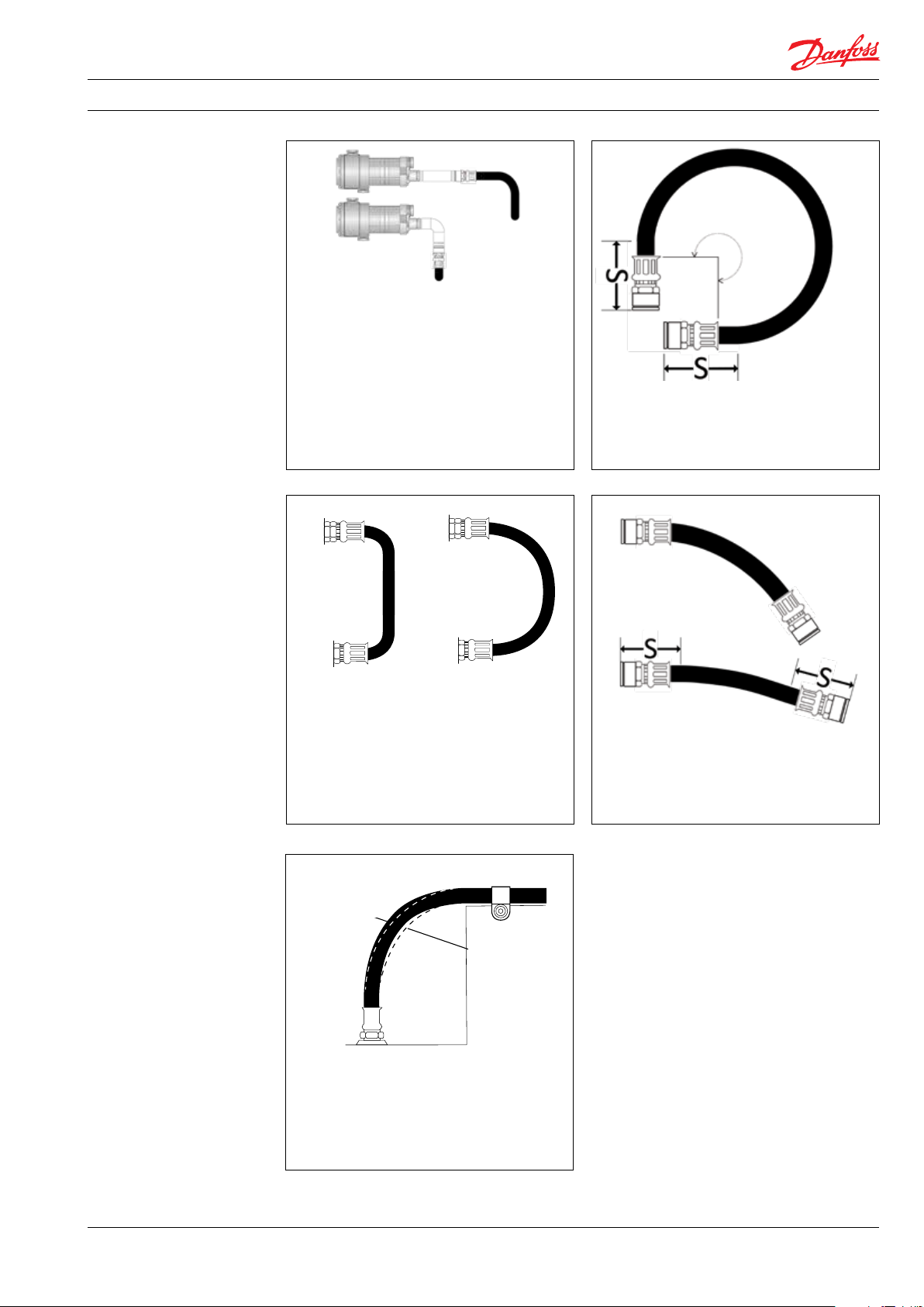
Instruction | Right and wrong - Hose assembly routing tips
The use of pipe or fittings between pump
and iSave connectors and hoses should
be avoided. Such configurations can apply
excessive loads on the connectors and can
cause connector and/or connector bolt
failure. If this cannot be avoided, the piping
system must be protected by either hose
whip restraints mounted directly to the
frame or the hard piping must be fixed relative to any pump/iSave movements.
MAX.
BENDING
ANGLE
If hose is bent, ensure max. bending angle
and distance S from each connector (see
table 1 on page 5).
WRONG
WRONG RIGHT
To prevent hose collapse and flow restriction,
hose bend radii should be kept as large as
possible. Tight bends can also compromise
the hose reinforcement and cause premature
hose failure. Refer to hose specification table
on page 6 for minimum bend radii.
NO
NO
PRESSURE
PRESSURE
RIGHT
HIGH
HIGH
PRESSURE
PRESSURE
WRONG
RIGHT
The hose must have a distance S before
bending starts.
To allow the hose to expand when
pressurized, clamps should not be used at
bends. If possible, do not clamp high and
low pressure lines together.
180R9357 | AQ265943679828en-001001 IOM iSave 50 - 70 | 02.2022
71
Page 72

Instruction | Right and wrong - Hose assembly routing tips
S
3. Hose specification
table
High pressure hoses
Code
number
180Z0228
connection
material
EN 1.4410
Pipe
Pipe connection
[A]
1.5" Vic. OGS Super duplex
1
Hose size
Inner
diameter
25.4 mm (1.0") 0.66 m (26") 152 mm (6.08"), max. 90° 79 mm (3.11”)
Hose length
ISO 1436
[B]
Bending radius S
180Z0229 1.5" Vic. OGS
180Z0167
180Z0140
180Z0263 2.5" Vic. OGS
180Z0280
180Z0619
180Z0618
180Z0612
18 0Z0611
180Z1000
180Z1001
Low pressure hoses
180Z0298 2.0” Vic. OGS
180Z0144 3.0” Vic. OGS
1.5" Vic. OGS Super duplex
2.0" Vic. OGS Super duplex
2.5" Vic. OGS Super duplex
2.5" Vic. OGS Super duplex
2.5" Vic. OGS Super duplex
3.0" Vic. OGS Super duplex
3.0" Vic. OGS Super duplex
3.0" Vic. OGS Super duplex
3.0" Vic. OGS Super duplex
Super duplex
EN 1.4410
EN 1.4410
EN 1.4410
)
Super duplex
EN 1.4410
EN 1.4410
EN 1.4410
EN 1.4410
EN 1.4410
EN 1.4410
EN 1.4410
EN 1.4410
Super duplex
EN 1.4410
Super duplex
EN 1.4410
25.4 mm (1.0")
38.0 mm (1.5") 1.16 m (45.7") 250 mm (9.84"), max. 180° 85 mm (3.35”)
50 mm (2.0") 1.25 m (49") 630 mm (24.8"), max. 90° 115 mm (4.53”)
50 mm (2.0") 1.78 m (70") 630 mm (24.8"), max. 180° 115 mm (4.53”)
50 mm (2.0") 1.00 m (39.4") 630 mm (24.8"), max. 90° 115 mm (4.53”)
65 mm (2.5") 1.78 m (70") 200 mm (7.87"), max. 270° 150 mm (5.90”)
65 mm (2.5")
76 mm (3.0") 1.79 m (70.5") 250 mm (9.84"), max. 270° 150 mm (5.90”)
76 mm (3.0") 1.00 m (39.4") 250 mm (9.84"), max. 90° 150 mm (5.90”)
76 mm (3.0") 1,25 m (49") 250 mm (9.84"), max. 180° 150 mm (5.90”)
76 mm (3.0") 1,6 m (63") 250 mm (9.84"), max. 180° 150 mm (5.90”)
1.16 m (45.7")
1.00 m
(9.4")
2.0 m
(79”)
2.0 m
(79”)
152 mm (6.08"), max. 180° 79 mm (3.11”)
200 mm (7.87"), max. 90° 150 mm (5.90”)
1)
The installation instuction for Style 77DX is located in the Victaulic document I-100 Field Installation Handbook (htpp://static.victaulic.com)
O. D.
r
α
S
180R9357 | AQ265943679828en-001001 IOM iSave 50 - 70 | 02.2022
When using flexible hoses, it is
recommened to use Hose Whip Restraint.
72
Page 73

Instruction | Right and wrong - Hose assembly routing tips
180R9357 | AQ265943679828en-001001 IOM iSave 50 - 70 | 02.2022
73
Page 74

© Danfoss | DCS (im) | 2019.05
180R9084 | 521B0540 | DKCFN.PI.000.D7.02 | 74
Page 75

Parts list
Energy recovery device
iSave 50 - 70
hpp.danfoss. com
Page 76

Parts list | Energy recovery device iSave 50-70
Table of Contents
Contents
1. General..................................................................................................................................................... 76
2. Parts list iSave 50-70............................................................................................................................ 77
3. Exploded view iSave 50-70 ...................................................................................... .......................79
4. Assembly unit iSave 50-70 Vertical mounting............................................................................... 80
5. Assembly unit drawing iSave 50-70 Vertitical mounting............................................................ 81
6. Assembly unit iSave 50-70 Horizontal mounting....................................................... ..................82
7. Assembly unit drawing iSave 50-70 Horizontal mounting........................................................ 83
8. Tool set iSave 50-70............................................................................................................................... 84
1. General
76 © Danfoss | DCS (im) | 2022.02
The parts list provides an overview of th content
of the various service kits for the iSave 50-70 as
well as exploded view of the iSave.
180R9357 | AQ265943679828en-001001 IOM iSave 50 - 70
Page 77

Parts list | Energy recovery device iSave 50-70
2. Parts list
iSave 50-70
Pos. Q ty. Description Material
1 4 Screw M8 AISI 316 X X
2 1 Cover Super Duplex
3 1 O-ring NBR X X
4 1 Shaft seal Ø35 NBR/hasteloy X
5 15 Screw M12 AISI 316 X
6 2 Bleeding plug G1/4" Super Duplex
7 2 O-ring NBR X
8 1 Ass. Motor flange Super Duplex/PEEK
10 2 O-ring NBR X
11 2 Rotor stop mashined PEEK X
12 2 O-ring NBR X
13 2 Side plate Ceramic X
14 2 O-ring NBR X
15 2 Rotor element Ceramic X
16 2 O -ring NBR X
17 1 Rotor Super Duplex
18 8 Vane PEEK/Super Duplex X
19 8 Pin PEEK X
20 1 Key AISI 316 X
21 1 Stator Super Duplex
22 4 Pin AISI 316 X
23 1 O-ring NBR X
24 1 3" Vic. Connector, HP Out Super Duplex
25 8 Screw M8 AISI 316 X
26 1 Intermediate flange Super Duplex/PEEK
27 15 Screw M12 AISI 316 X
28 1 O-ring NBR X
29 1 3" Vic. Connector, LP In Super Duplex
30 1 Lifting eye M12 AISI 316
31 4 Screw M8 AISI 316 X
101 2 O-ring NBR X
102 4 Clips for retainer plate PEEK X
103 4 Pin Duplex X
104 1 Port plate (Feed) PEEK/Super Duplex X X
105 2 Valve plate Super Duplex X
106 16 Back-up ring PTFE X
107 16 O -ring NBR X
180 F4133
Shaft Seal Kit iSave 50 -70
180 F4132
Screw and Seal Kit iSave 50 -70
180 F4134
Coupling K it iSave 50-70
180 F4135
Port Plate K it PE iSave 50
180 F4136
Port Plate K it PE iSave 70
180 F4137
Vane Kit iSave 50 -70
180 F4138
Valve Plate Kit PE iSave 50-70
180 F4139
Rotor/side plade Kit iSave 50 -70
Note: Danfoss reccommends always to use seals and screw kit for inspection and repair.
© Danfoss | DCS (im) | 2021.04
180R9357 | AQ265943679828en-000901 IOM iSave 50 - 70
77
|
Page 78

Parts list | Energy recovery device iSave 50-70
2. Parts list cont.
iSave 50-70
Pos. Q ty. Description Material
108 1 Spring stop Super Duplex
109 12 Compression spring Hastelloy C276 X
110 1 O-ring NBR X
111 1 Cylinder barrel Super Duplex
112 1 Port plate (Brine) PEEK/Super Duplex X X
113 2 Pin AISI 316 X
114 1 Housing Duplex
115 6 Stud bolt M12 Duplex
116 6 Wash er M12 AISI 316 X
117 6 Nut AISI 316 X
118 1 Portflange Super Duplex
119 2 O-ring NBR X
120 4 Screw M8 AISI 316 X
121 1 3" Vic. connector LP Out Super Duplex
122 6 Screw M8 AISI 316 X
123 1 3" Vic. connector HP IN Super Duplex
124 1 Lifting eye M12 AISI 316
125 3 O-ring NBR X
126 3 Bleeding plug G1/4" Super Duplex X
203 2 Coupling Super Duplex X
204 1 So ftex 38/45 Hytrel X
205 4 Pin Duplex X
206 8 Screw M8 Super Duplex X
1 Service instruction X X X X X X X X
180 F4133
Shaft Seal Kit iSave 50 -70
180 F4132
Screw and Seal Kit iSave 50 -70
180 F4134
Coupling K it iSave 50-70
180 F4135
Port Plate K it PE iSave 50
180 F4136
Port Plate K it PE iSave 70
180 F4137
Vane Kit iSave 50 -70
180 F4138
Valve Plate Kit PE iSave 50-70
180 F4139
Rotor/side plade Kit iSave 50 -70
Note: Danfoss reccommends always to use seals and screw kit for inspection and repair.
78 © Danfoss | DCS (im) | 2022.02
180R9357 | AQ265943679828en-001001 IOM iSave 50 - 70
Page 79

Parts list | Energy recovery device iSave 50-70
3. Exploded view
iSave 50-70
© Danfoss | DCS (im) | 2021.04
180R9357 | AQ265943679828en-000901 IOM iSave 50 - 70
79
|
Page 80

Parts list | Energy recovery device iSave 50-70
4. Assembly unit
iSave 50-70
Vertical mounting
iSave 50-70 Assembly Unit - Vertical mounting IEC NEMA
Pos. Qty. Description Code No. Code No.
iSave 50, Vertical, IEC200L, 18.5 kW 180F7022
iSave 50, Vertical, NEMA324/6T, 30HP 180U0004
iSave 70, Vertical, IEC200L, 18.5 kW 180F7024
iSave 70, Vertical, NEMA324/6T, 30HP 180U0006
iSave 50-70 without motor
1 1 iSave 50 180F7020
1 1 iSave 70 180F7021
Motor
2 1 Motor 18.5 kW IEC200 6-pole 3x400 V IE3 180Z0530
2 1 Motor 324TC 30 HP 3PH 1200 230/460/380 180U2370
5 4 Screw (not inluded in kit)
6 4 Washer (not included in kit)
iSave 50 - 70 coupling kit 180Z4003 180U2309
3 1 Bell housing X X
4 1 Coupling X X
22 4 Screw M12 X X
23 4 Washer M12 X X
24 1 Grommet sealing X X
Base frame vertical 180Z4025
12 1 Base frame X X
13 2 Bracket, long X X
14 2 Bracket, short X X
15 4 Screw M12 X X
16 8 Washer M12 X X
17 4 Nut M12 X X
18 4 Screw M10 X X
19 16 Washer Ø10.5 X X
20 4 Nut M10 X X
21 8 Screw M10 X X
80 © Danfoss | DCS (im) | 2022.02
180R9357 | AQ265943679828en-001001 IOM iSave 50 - 70
Page 81

Parts list | Energy recovery device iSave 50-70
5. Assembly unit drawing
iSave 50-70
Vertical mounting
© Danfoss | DCS (im) | 2021.04
180R9357 | AQ265943679828en-000901 IOM iSave 50 - 70
81
|
Page 82

Parts list | Energy recovery device iSave 50-70
6. Assembly unit
iSave 50-70
Horizontal mounting
iSave 50-70 Assembly Unit - Horizontal mounting IEC NEMA
Pos. Qty. Description Code No. Code No.
iSave 50, Horizontak, IEC200L, 18.5 kW 180F7023
iSave 50, Horizontal, NEMA324/6T, 30HP 180U0003
iSave 70, Horizontal, IEC200L, 18.5 kW 180F7025
iSave 70, Horizontal, NEMA324/6T, 30HP 180U0005
iSave 50-70 without motor
1 1 iSave 50 180F7020
1 1 iSave 70 180F7021
Motor
2 1 Motor 18.5 kW IEC200 6-pole 3x400 V IE3 180Z0530
2 1 Motor 324TC 30 HP 3PH 1200 230/460/380 180U2370
5 4 Screw (not inluded in kit)
6 4 Washer (not included in kit)
iSave 50 - 70 coupling kit 180Z4003 180U2309
3 1 Bell housing X X
4 1 Coupling X X
22 4 Screw M12 X X
23 4 Washer M12 X X
24 1 Grommet sealing X X
Base frame horizontal 180Z4007
12 1 Base frame X X
13 1 Bracket, support X X
14 1 Bracket, service X X
15 10 Screw M10 X X
16 16 Washer Ø10 X X
17 4 Nut M10 X X
18 8 Washer Ø17 X X
19 4 Screw M16 X X
20 4 Nut M16 X X
21 2 Screw M10 X X
82 © Danfoss | DCS (im) | 2022.02
180R9357 | AQ265943679828en-001001 IOM iSave 50 - 70
Page 83

Parts list | Energy recovery device iSave 50-70
7. Assembly unit drawing
iSave 50-70
Horizontal mounting
© Danfoss | DCS (im) | 2021.04
180R9357 | AQ265943679828en-000901 IOM iSave 50 - 70
83
|
Page 84

Parts list | Energy recovery device iSave 50-70
8. Tool set
iSave 50-70
Qty. Designation
1 Back-up ring tool x
2 Bushing for valve plate x
2 M6 screw x
2 Washer M6 x
2 Nut M6 x
2 M16 washer x
2 M8 screw x
1 M8 lifting eye x
1 Shaft seal tool x
1 24 mm crow foot socket x
1 19 mm socket x
1 3/8” extension x
1 Torque wrench 3/8” x
1 4 mm Allen key x
2 Screw driver x
1 10 mm HEX socket x
1 6 mm HEX socket x
1 Nylon hammer x
1 10 mm fork wrench x
1 Screw driver x
1 16 mm socket x
1 Service instruction x
180F4140 iSave 50-70 Tool kit
84 © Danfoss | DCS (im) | 2022.02
180R9357 | AQ265943679828en-001001 IOM iSave 50 - 70
Page 85

Parts list | Energy recovery device iSave 50-70
© Danfoss | DCS (im) | 2021.04
180R9357 | AQ265943679828en-000901 IOM iSave 50 - 70
85
|
Page 86

86 | © Danfoss | DCS (im) | 2021.03
180R9392_AX299849991270en-000701
Page 87

Electric Motors
Motor Manual
hoyermotors.com
Page 88

Motor
Manual
General
This manual concerns the following types of standard
induction motors from Hoyer:
HMA3, HMC3, HMA2, HMC2, HMD, HMT, MS, Y2E1, Y2E2, YDT
These motors are manufactured in accordance with IEC/EN
60034-4 and IEC/EN 60072.
Motors are rated for the ambient temperature range -20°C to
+40°C and site altitudes ≤1000 m above sea level.
Low-voltage motors are components for installation in
machinery. They are CE marked according to the Low Voltage
Directive 2014/35/EU.
Motors not fulfilling the IE3 efficiency level must be equipped
with a variable speed drive when used in EU.
Transport and storage
Check the motor for external damage immediately upon
receipt and, if found, inform the forwarding agent right away.
Check all rating plate data, and compare it with the
requirement of the motor.
Turn the shaft by hand to check free rotation, remove
transport locking if used.
Transport locking must be used again for internal transport
also. It is also important that transport locking is used when
motors are transported mounted on equipment.
All motors should be stored indoors, in dry, vibration- and
dust-free conditions.
Lifting eyebolts must be tightened before use. Damaged
eyebolts must not be used, check before use. Lifting eyes at
motor must not be used to lift the motor when it is attached
to other equipment.
Before commissioning, measure the insulation impedance. If
values are ≤ 10MΩ at 25°C, the winding must be oven dried.
The insulation resistance reference is halved for each 20°C
rise in motor temperature.
It is recommended that shafts are rotated periodically by
hand to prevent grease migration.
etc.) using suitable tools, never hit the drive components
with a hammer as this will cause damage to the bearing.
The motor are balancing with half key, ensure that the drive
components are also the same.
Correct alignment is essential to avoid bearing, vibration and
shaft failure.
Use appropriate methods for alignment.
Re-check the alignment after the final tightening of the bolts
or studs.
Check that drain holes and plugs face downwards. We
recommend opening the drain hole for motors placed
outdoors and not running 24 hours / day, so that the motor
can breathe, thus ensuring a dry motor.
Electrical connection
Work is only permitted to be carried out by qualified
specialists and must to be carried out in accordance with
local regulations.
Before work commences, ensure that all power is switched
off and cannot be switched on again. This also applies to the
auxiliary power circuits, e.g. anti-condense heaters.
Check that supply voltage and frequency are the same as
rated data.
Motors can be used with a supply deviation of ± 5% voltage
and ± 2% frequency, according to IEC60034-1.
Connection diagrams for main supply and accessory as PTC
or heater are located inside the terminal box.
Connections must be made in such a way as to ensure that
a permanently safe electrical connection is maintained, both
for the main supply and the earth connection.
We recommend that crimped connections are made in
accordance with IEC 60352-2.
Tightening torques for terminal board screws:
Thread M5 M6 M8 M10 M12 M16 M20 M24
T.(Nm) 2.5 3.5 7 12 18 35 55 80
Installation
The motor must be fixed on a stable, clear and flat foundation.
It must be sufficiently rigid to withstand possible short
circuit forces.
It is important to ensure that the mounting conditions do
not cause resonance with the rotational frequency and the
doubled supply frequency.
Only mount or remove drive components (pulley, coupling,
88
180R9357 | AQ265943679828en-001001 IOM iSave 50 - 70 | 02.2022
Ensure that the terminal box is clean and dry.
Unused glands must be closed with blind caps.
Check the terminal box gasket before it is remounted.
Maintenance
Inspect the motor at regular intervals, keep it clean and
ensure free ventilation air flow, check the condition of shaft
seals and replace if necessary. Both electrical and mechanical
Page 89

Motor
Manual
connections must be checked and tightened if necessary.
Bearing size and type are specified on the rating plate. Motor
types HMA3 and HMC3 is as standard with lifetime greased
bearings in motors size ≤180 for cast iron and size ≤132 for
aluminium. Motor types HMA2 and HMC2 is as standard
with lifetime greased bearing in motors size ≤225.
Motor types MS and Y2E is as standard with lifetime greased
bearing in motors size ≤160.
Typical duty hours for lifetime lubricated bearings.
Frame size Poles Typical lifetime
56 - 160 2 - 8 40,000h
180 2 35,000h
200 2 27,000h
225 2 23,000h
180 - 225 4 - 8 40,000h
Motors with a re-greasing system must be lubricated with
high quality lithium complex grease, NLGI grade 2 or 3, with
a temperature range of between -40°C to +150°C.
Motors are normal fitted with a data plate with greasing
information; if it is missing use the following re-greasing
intervals.
Frame
size
160 20 4200 7000 8500 8500
180 20 4200 7000 8500 8500
200 25 3100 6500 8500 8500
225 25 3100 6500 8500 8500
250 35 2000 6000 7000 7000
280 35 2000 6000 7000 7000
315 50 1500 5500 6500 6500
355 60 1000 4000 5000 6000
400 80 800 3000 4000 6000
Grease
(g)
2 pole
(h)
4 pole
(h)
6 pole
(h)
8 pole
(h)
Grease the motor while running, open the grease outlet plug
and let the motor run 1-2 hours before the outlet grease plug
is closed again.
Grease the motor for the first time during commissioning.
The following applies in general for both lifetime lubricated
and re-lubricated bearings:
At 60Hz the time will be reduced by app. 20%.
Data for vertically mounted motors are half of the above
values.
The table values are based on an ambient temperature of
25°C. The values must be halved for every 15K increase in
bearing temperature.
Higher speed operations, e.g. frequency converter drive will
require shorter greasing intervals. Typically, doubling the
speed will reduce the values by 50%.
Special note for Atex Zone 22 and nA motors
Designation of motor according to IEC standard:
II 3D Ex tc IIIB T120°C
II 3G Ex nA IIC T3
The hazardous 3-phase asynchronous motors are in
accordance with International standard IEC 60079-31 and
IEC 60079-15.
Only one electrical installation may be installed in one
specified area (zone).
Only certificated cable glands may be used. Unused glands
must be closed.
Connections must be made in such a way as to ensure that
a permanently safe electrical connection is maintained, both
for the main supply and earth connection.
Installations must be in accordance with actual standards
for installation in hazardours area.
It is recommended that the IEC standard is followed according
to temperature and dust on the motor surface.
The use of motors with so much surface dust that the motor
temperature increases is not permitted.
Regularly cleaning is recommended.
The radial shaft sealing ring is part of the ATEX certification.
It is important that the ring is always intact.
The shaft sealing must be regularly checked, and if dry it
must be lubricated. It is recommended that the seal is relubricated regularly.
Always use the original seal ring when replaced.
Replacing bearings also means replacing the seals.
All machines must be inspected regularly for mechanical
damage.
The user is responsible for changing parts in accordance
with the lifetime of parts, in particular:
bearings, grease and lubrication of shaft sealing.
Maintenance, repairs and replacement on this type must
only be carried out by qualified specialists.
180R9357 | AQ265943679828en-001001 IOM iSave 50 - 70 | 02.2022
3
89
Page 90

Connection diagram
Anschlußdiagram
Anslutningdiagramm
Forbindelsesdiagram
Aansluitdiagram
Connection
Conexión
Collegamento
Schemat polacsen
90
180R9357 | AQ265943679828en-001001 IOM iSave 50 - 70 | 02.2022
Page 91

180R9357 | AQ265943679828en-001001 IOM iSave 50 - 70 | 02.2022
91
Page 92

Hoyer Motors, Motor Manual, April 2019
Head Offices
Over Hadstenvej 42 · DK-8370 Hadsten
T +45 86 98 21 11 · F +45 86 98 17 79
hoyermotors@hoyermotors.com
19 Jingwu Middle Road · Beilun District
T +86 574 26 28 15 77 · F + 86 574 2628 1573
hoyermotors@hoyermotors.cn
Important notice.
Denmark
CVR no. 17 63 06 95
hoyermotors.com
China
Ningbo 315821 · Zhejiang
hoyermotors.cn
Text and data in this catalogue are not binding and we reserve the right to implement changes without further notice.
Branch Offices
Germany
Landsberger Straße 155 · 80687 München
T +49 89 700 88 235 · F +49 89 543 56 333
germany@hoyermotors.com
hoyermotors.com
Sweden
Liljeholmsstranden 5 · PO box 44017
SE-100 73 Stockholm
T +46 8 446 877 13
sweden@hoyermotors.com
hoyermotors.com
Vasteland 78 · 3011 BN, Rotterdam
Benelux
Tel. +31 10 420 35 20 · Fax.+31 10 420 44 51
benelux@hoyermotors.com
hoyermotors.com
Korea
302ho · Code square · 3150-1 · Daejeo 2-dong
Gangseo-gu · Busan · Korea
T +82 51 996 0251 · F +82 51 996 0252
korea@hoyermotors.com
hoyermotors.com
92
180R9357 | AQ265943679828en-001001 IOM iSave 50 - 70 | 02.2022
 Loading...