

Page 1
Service guide
Instruction
Energy recovery device
iSave 40
Disassembling and assembling
Disassembling and assembling
iSave 40
hpp.danfoss.com
ro-solutions.com
Page 2
Service guide | Disassembling and assembling iSave 40
Table of Contents
1. General information.....................................................................2
2. Disconnect the iSave from electric motor ................................................3
3. Disassembling the booster pump .......................................................5
4. Assembling the booster pump ..........................................................8
5. Disassembling the pressure exchanger .................................................13
6. Assembling the pressure exchanger . . . . . . . . . . . . . . . . . . . . . . . . . . . . . . . . . . . . . . . . . . . . . . . . . . . . 15
7. Assembling the cylinder drum in pressure exchanger ...................................19
8. Changing spring in the rotor ...........................................................20
8.1 Disassembling .........................................................................20
9. Exploded view vane pump .............................................................21
10. Exploded viewpressure exchanger .....................................................22
11. Exploded view iSave ...................................................................23
12. Exploded view iSave on baseplate, horizontal ...........................................24
13. Exploded view iSave on foot, vertical ...................................................25
1. General information
This document illustrates instructions for
disassembling and assembling the iSave 40.
To understand the design of the iSave, see
exploded views starting on page 21.
Always use suitable lifting equipment.
Important!
It is essential that the iSave is serviced in
conditions of absolute cleanliness.
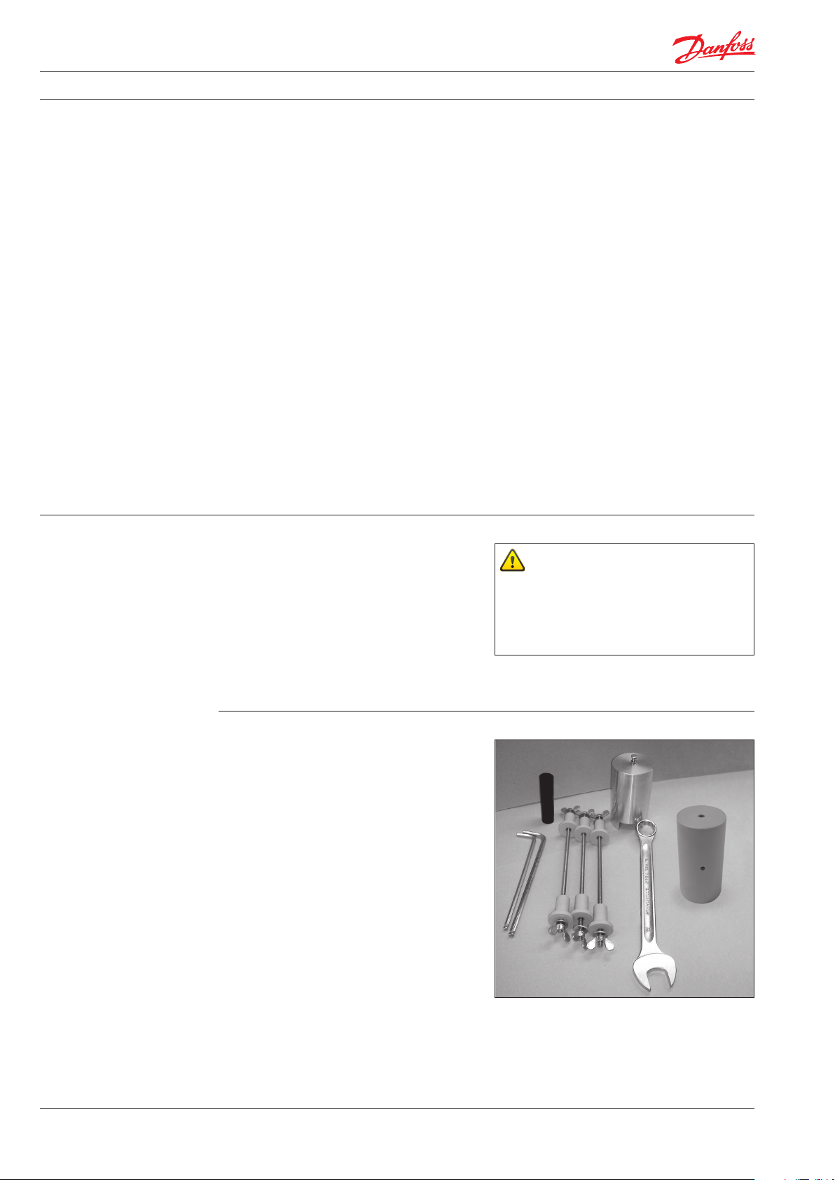
Tools needed to disassemble the iSave:
Parts included in tool set (180F4112):
• 6 mm and 8 mm allen key
• C-wrench 24 mm
• 1 M6 bolt and nut
• Handel for rotor assembly
• Tool for shaft seal assembly
• Tool for retainer assembly
• 3 press bolt-set for valve plate assembly
Parts not included in tool set:
• 2 screwdrivers
• Torque wrench 10-60 Nm
• The weight of the iSave, including
electric motor, is about 260 kg (573 lb).
• The weight of the pressure exchanger
alone is about 75 kg (165 lb).
• The weight of the booster pump
alone is about 50 kg (110 lb).
To prevent cold welding, lubricate threads of the
screws with PTFE lubrication type and screw
them into the component and tighten by hand.
2
180R9242 | AX073186502910 en-000701 | 01.2022
Page 3
Instruction Disassembling and assembling iSave 40
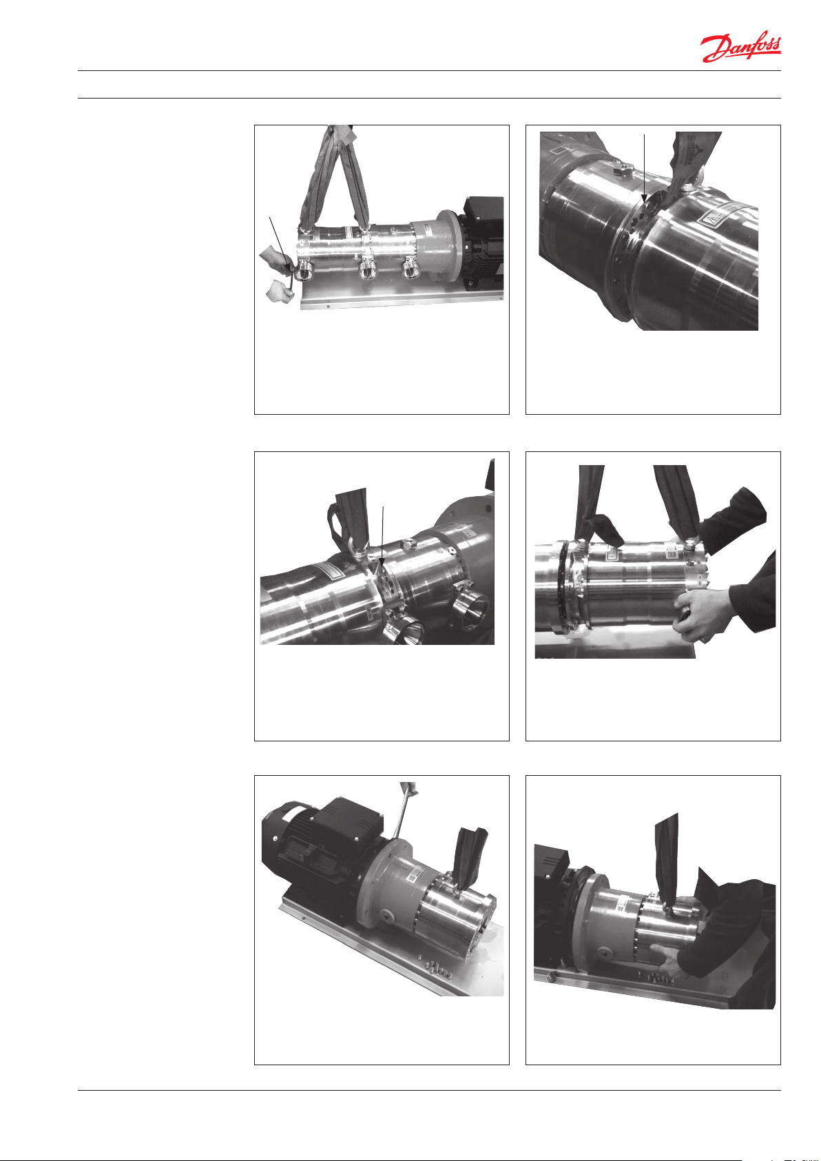
2. Disconnect the iSave
from electric motor
1. Apply a light lifting force on the pressure
exchanger and disconnect the support
bracket between the pressure exchanger
and base plate.
3. Unscrew the 2 upper bolts.
2. Unscrew 10 bolts in the adapter flange
between booster pump and pressure
exchanger. Leave the 2 upper bolts
tighten.
4. Carefully pull and lift the pressure
exchanger from the booster pump.
5. To disconnect the bell housing, unscrew
the 4 bolts on the electric motor.
180R9242 / 521B1213 / DKCFN.PI.003.R2.02 / 09.2013
6. Carefully pull and lift the booster pump
from the electric motor.
3
Page 4
Service guide | Disassembling and assembling iSave 40
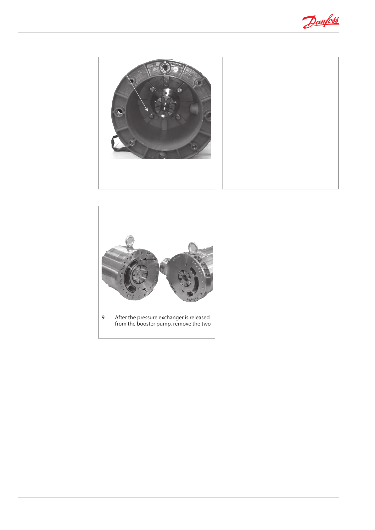
7. Disassemble the bell housing from the
booster pump by unscrewing the 4 bolts
in the bell housing.
9. After the pressure exchanger is released
from the booster pump, remove the two
guide pins.
8. It is also possible to disconnect the
complete unit from the motor first. In this
case, please follow step 1, 5, 6 and 7
afterwards.
4
180R9242 | AX073186502910 en-000701 | 01.2022
Page 5
Service guide | Disassembling and assembling iSave 40
3. Disassembling the
booster pump
M8x20 bolts marked A4
If flange cannot be removed easily, use two
M8 bolts.
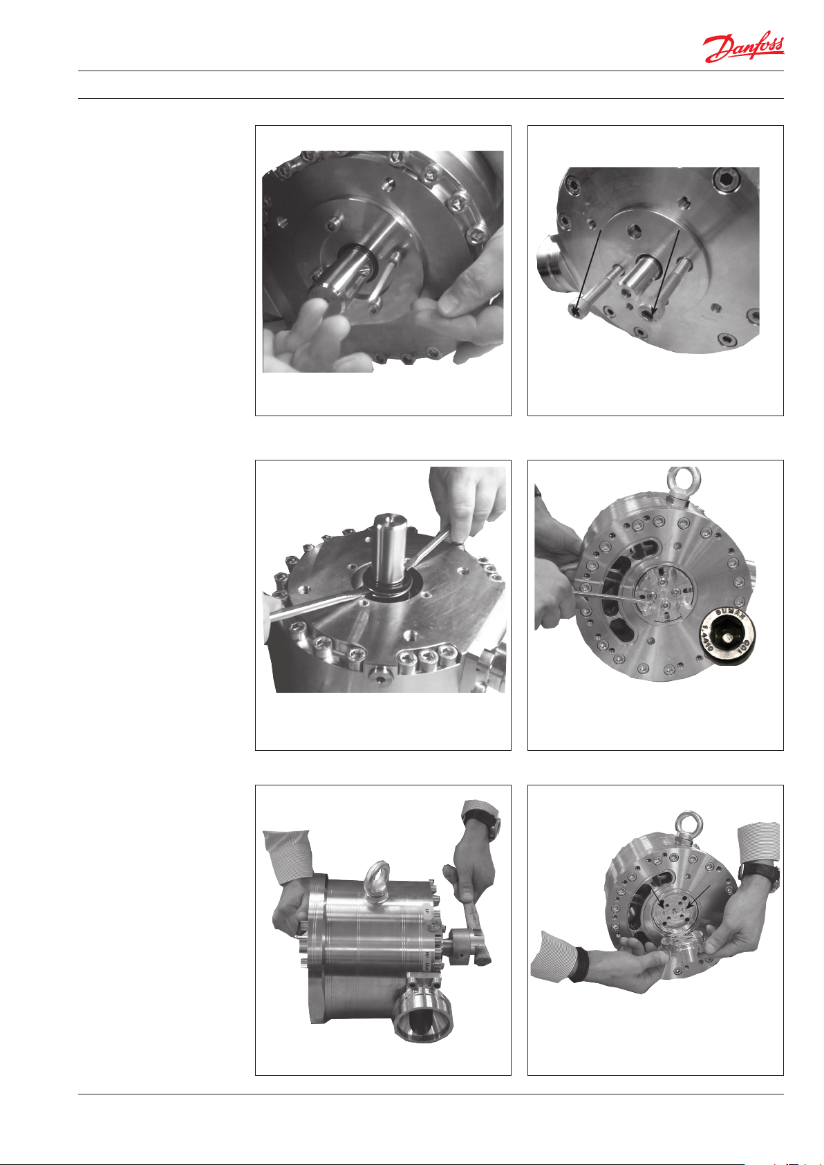
1. Disassemble the flange for shaft seal.
3. If coupling has to be changed, follow the
next two steps.
4 x special M8x20 bolts
marked 1.4410
2. Wet the shaft seal first with clean filtered
water. Carefully lift the shaft seal by using
2 screwdrivers.
4. Unscrew the four special M8x20 bolts
marked 1.4410. Use a hammer handle at
the opposite end to prevent the shaft from
turning.
5. Remove coupling and the two pins.
180R9242 | AX073186502910 en-000701 | 01.2022
5
Page 6
Service guide | Disassembling and assembling iSave 40
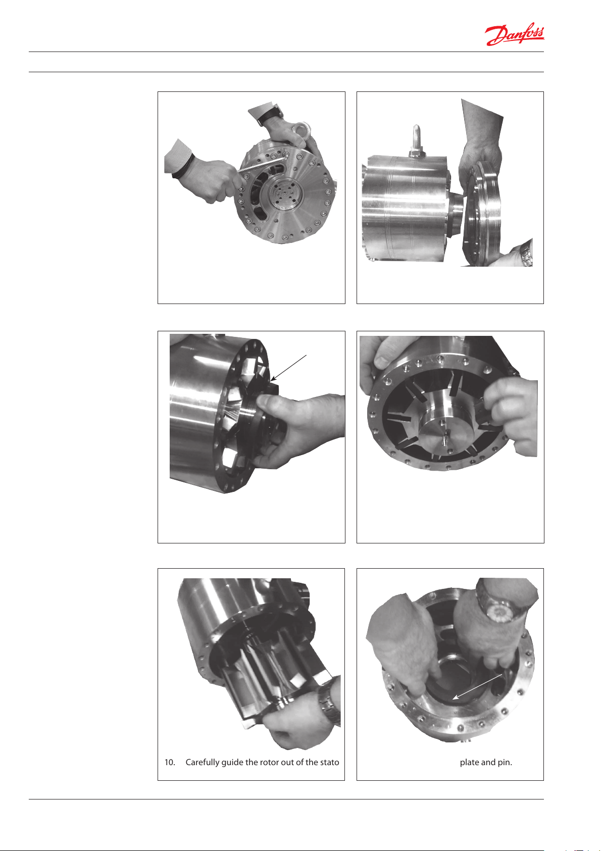
6. Loosen all the bolts in the adapter flange. 7. Carefully disassemble adapter flange and
port plate from the stator ring.
9. Remove the 8 vanes.8. Remove the sealing plate.
10. Carefully guide the rotor out of the stator. 11. Remove the sealing plate and pin.
6
180R9242 | AX073186502910 en-000701 | 01.2022
Page 7
Service guide | Disassembling and assembling iSave 40
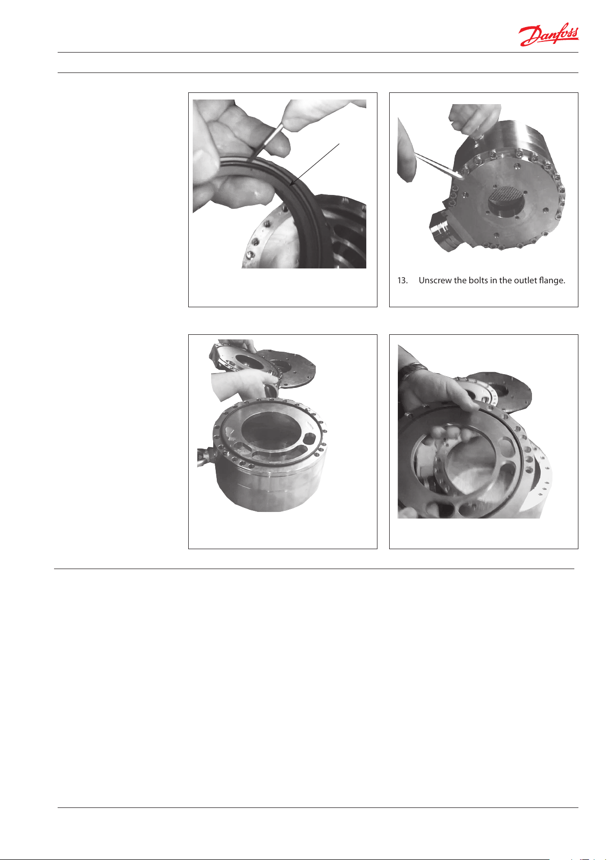
12. Remove the O-ring from the sealing
13. Unscrew the bolts in the outlet flange.
plate.
14. Remove the HP outlet flange. 15. Remove the port flange.
180R9242 | AX073186502910 en-000701 | 01.2022
7
Page 8
Service guide | Disassembling and assembling iSave 40
4. Assembling the
booster pump WARNING:
Do not use silicone when assembling the
iSave. Do not reuse disassembled O-rings;
they might be damaged. Always use new
O-rings.
Important:
It is essential that the pump is serviced in
conditions of absolute cleanliness. All parts
must be absolutely clean before mounting.
Lubrication:
• To prevent seizing-up, lubricate all threads
with PTFE lubrication type.
• It is important to lubricate ALL parts to be
assembled with clean filtered water
(Especially all PEEK parts).
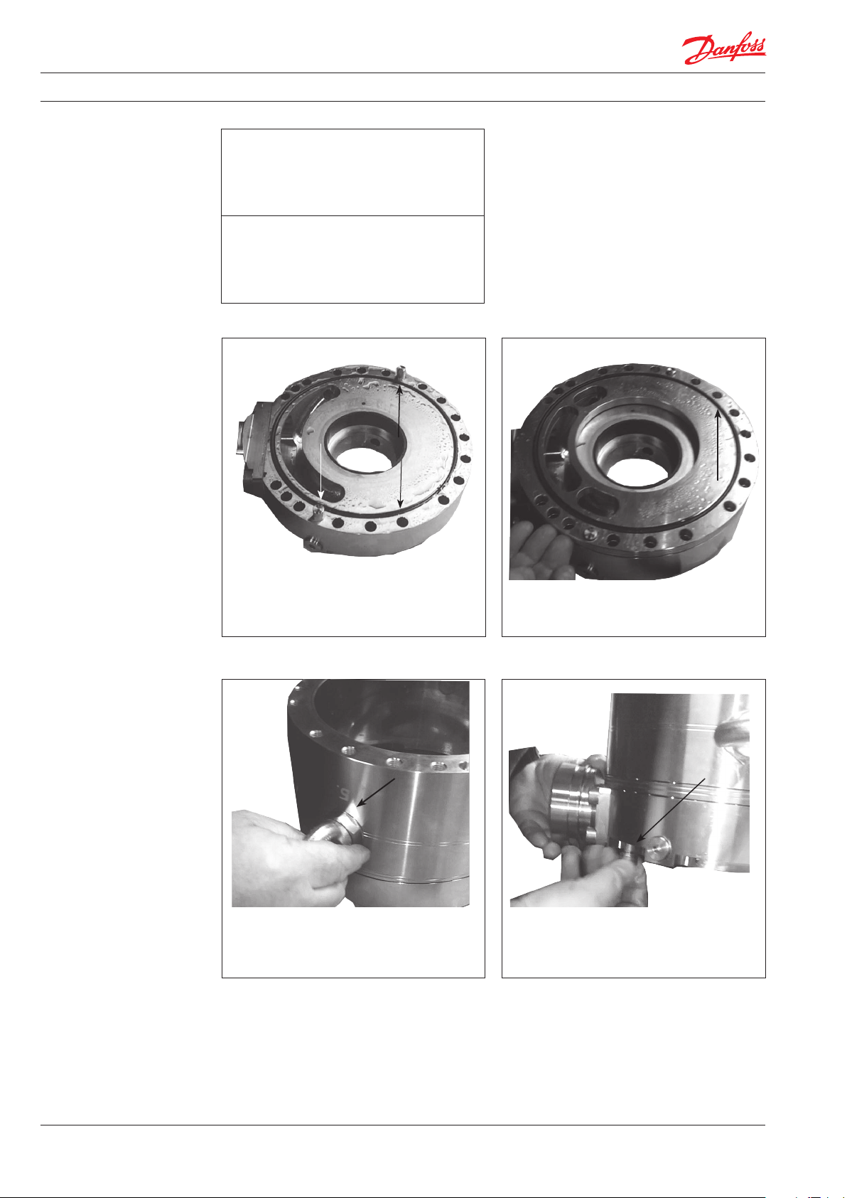
1. Place the HP outlet flange on the desk
and mount the O-ring and 2 pins.
3. Turn the stator with the two holes for the
lifting eye closest to the port plate and
position the stator on the 2 pins.
2. Align the port plate-out on the two pins
and mount the O-ring on the port plate.
4. From down side up and by hand, screw in
two bolts in the stator.
8
180R9242 | AX073186502910 en-000701 | 01.2022
Page 9

Service guide | Disassembling and assembling iSave 40
5. Tighten the bolts by using an allen key.
6. Tilt the flange and stator; assemble and
screw in the rest of the bolts in the flange.
Tighten bolts to a torque of 60 ±6 Nm.
7. Assemble and position the two pins in the
pin holes.
9. Mount the O-ring in the sealing plate and
guide pin in flange.
It is important to lubricate to ensure the
O-ring does not drop out.
180R9242 | AX073186502910 en-000701 | 01.2022
9
Page 10

Service guide | Disassembling and assembling iSave 40
10. Position the sealing plate on the guide
pin.
Ensure correct choice of sealing plate.
Only one sealing plate fits the guide pin.
12. By using the handle tool provided, carefully
lever the rotor into the stator.
11. Position the 8 pins in the rotor. 2 pins in
each hole.
13. Fit the 8 vanes into each slot. Notice vane
position. Place the straight site of the
vane onto the pin with the mark down
ward.
No mark on
this side
14. Orient the vanes with correct end into
rotor. See the arrow below.
10
180R9242 | AX073186502910 en-000701 | 01.2022
15. Assemble the new O-ring on the adapter
flange.
Page 11

Service guide | Disassembling and assembling iSave 40
16. Assemble the new O-ring on the port
plate-in.
18. Assemble the new O-ring on the correct
sealing plate.
It is important to lubricate to ensure the
O-ring does not drop out.
17. Position the port flange in on the adapter
flange and position the two guide pins.
19. Position the guide pin in the adapter
flange.
20. Position the sealing plate over the guide
pin.
180R9242 | AX073186502910 en-000701 | 01.2022
21. Carefully position the adapter flange
assembly into the two guide pin holes.
11
Page 12

Service guide | Disassembling and assembling iSave 40
22. Mount two bolts in the adapter flange. 23. Mount all bolts in the adapter flange.
Tighten the bolts to a torque of 60±6 Nm.
24. Turn the pump with shaft upwards.
Lubricate the shaft and shaft seal with
clean filtered water. Mount the shaft seal
with the carbon ring upwards.
26. Lubricate and press new ceramic ring into
the shaft seal cover by using the press
bush tool.
WARNING:
Ensure that the face with rubber seal is
positioned against shoulder in shaft seal
flange.
25. Using the shaft tool provided, carefully
press down the shaft seal to the shoulder
of the shaft.
M8x20 bolts marked A4
27. Mount a new O-ring on the flange for
shaft seal and assemble the minor flange
on top of the flange. Tighten M8x20 bolts
marked A4 to a torque of 30 ±3 Nm.
12
180R9242 | AX073186502910 en-000701 | 01.2022
Page 13

Service guide | Disassembling and assembling iSave 40
4 x special M8x20 bolts
marked 1.4410
5. Disassembling the
pressure exchanger
28. Mount the two pins and the coupling
part.
3 x special M8x20 bolts
marked 1.4410
1. Unscrew the 3 special M8x20 bolts marked
1.4410.
29. Mount the four special M8x20 bolts
marked 1.4410 and tighten them to a
torque of 35 ±3.5 Nm.
2. Remove coupling and the 3 pins.
3. Unscrew all the bolts. 4. Carefully lever the flange and port plate
from the casing.
180R9242 | AX073186502910 en-000701 | 01.2022
13
Page 14

Service guide | Disassembling and assembling iSave 40
5. Carefully take the cylinder barrel assem bly out of the casing.
6. Remove port plate and the two pins.
7. Carefully lever the 2 valve plate assembly
free with help from 2 screwdrivers.
14
180R9242 | AX073186502910 en-000701 | 01.2022
Page 15

Service guide | Disassembling and assembling iSave 40
6. Assembling the
pressure exchanger
WARNING:
Do not use silicone when assembling the
iSave. Do not reuse disassembled O-rings;
they might be damaged. Always use new
O-rings.
Important:
It is essential that the pump is serviced in
conditions of absolute cleanliness. All parts
must be absolutely clean before mounting.
Lubrication:
• To prevent seizing-up, lubricate all threads
with PTFE lubrication type.
• It is important to lubricate ALL parts to be
assembled with clean filtered water
(Especially all PEEK parts).
Assembling cylinder barrel in pressure
exchanger, see page 19.
Follow step 1-3 if LP in flange has been disassembled from casing.
1. Assemble the O-ring on the LP in port
flange.
M8x20 bolts marked A4
3. Position the LP in flange on the guide pin
and assemble all the bolts into the casing.
Tighten the bolts to a torque of 30 ±3 Nm.
2. Position the guide pin into the casing.
4. Turn the assembly and position the two
guide pins in the flange inside the casing.
180R9242 | AX073186502910 en-000701 | 01.2022
15
Page 16

Service guide | Disassembling and assembling iSave 40
5. Position the port plate on the flange
using the two guide pins as guide. Only
one port plate fits.
7. Carefully guide the cylinder barrel into the
flange bearing.
6. Mount the provided M6 threaded rod into
the shaft of the cylinder barrel.
8. Assemble the O-ring on the HP/LP flange
and position the two guide pins into the
flange.
9. Position the port plate on the HP/LP
10. Position the guide pin into the casing.
flange using the two guide pins as guide.
Only one port plate fits.
16
180R9242 | AX073186502910 en-000701 | 01.2022
Page 17

Service guide | Disassembling and assembling iSave 40
11. Carefully position the flange assembly
onto the guide pin in the casing.
12. Carefully assemble a bolt into the casing
to ensure that flange assembly stays in
place.
13. Assemble all the bolts and tighten them to
a torque of 30 ±3 Nm.
4 x special M8x20 bolts
marked 1.4410
15. Tighten four special M8x20 bolts marked
1.4410 to a torque of 35 ±3,5 Nm.
180R9242 | AX073186502910 en-000701 | 01.2022
14. Mount the 3 pins in shaft and place the
coupling part.
16. Assemble booster pump and pressure
exchanger. Mount the two guide pins
and coupling spacer.
17
Page 18

Service guide | Disassembling and assembling iSave 40
17. Tighten bolts to a torque of 60 ±6 Nm.
7. Assembling the
cylinder barrol in
pressure exchanger
O-ring
Back-up ring
The shaft is normally not a wear part and can
only be changed by Danfoss.
1. Assemble back-up rings and O-rings on
the valve plates. Back-up rings first.
2. Lubricate the O-rings and back-up rings
with clean filtered water and position the
two valve plates into the rotor ends.
3. Using the tools provided gently screw in
the valve plates.
4. Check the distance between the two valve
plates and the cylinder barrel. Adjust the
distance if necessary.
18
180R9242 | AX073186502910 en-000701 | 01.2022
Page 19

Service guide | Disassembling and assembling iSave 40
Small shaft diameter: No distance. Large shaft diameter: Distance 4-5 mm.
8. Changing springs in
the pressure exchange
rotor.
It is basically not necessary to change the
springs in the rotor. If needed, follow the
guidelines below:
8.1 Disassembling
Using the tool provided, press down the
retainer and remove/cut the O-ring, and
remove retainer. 1. Replace springs in the rotor.
180R9242 | AX073186502910 en-000701 | 01.2022
19
Page 20

Service guide | Disassembling and assembling iSave 40
2. Assemble the retainer over the springs. 3. Assemble the O-ring over the retainer.
4. Using the tool provided, press down the
retainer by tightening the nut until the
O-ring is placed in the recess.
5. Carefully lever the bolt and tool assembly
and check the O-ring assembly.
20
180R9242 | AX073186502910 en-000701 | 01.2022
Page 21

Service guide | Disassembling and assembling iSave 40
9. Exploded view
vane pump
M8x20 Bolts marked A4
180R9242 | AX073186502910 en-000701 | 01.2022
21
Page 22

Service guide | Disassembling and assembling iSave 40
10. Exploded view
pressure exchanger
22
M8x20
bolts
marked A4
180R9242 | AX073186502910 en-000701 | 01.2022
Page 23

Service guide | Disassembling and assembling iSave 40
11. Exploded view iSave
Special M8x20
bolts marked
1.4410
180R9242 | AX073186502910 en-000701 | 01.2022
23
Page 24

Service guide | Disassembling and assembling iSave 40
12. Exploded view
iSave on base plate,
horizontal
24
180R9242 | AX073186502910 en-000701 | 01.2022
Page 25

Service guide | Disassembling and assembling iSave 40
13. Exploded view
iSave on foot, vertical
180R9242 | AX073186502910 en-000701 | 01.2022
25
Page 26

Service guide | Disassembling and assembling iSave 40
26
180R9242 | AX073186502910 en-000701 | 01.2022
Page 27

Service guide | Disassembling and assembling iSave 40
180R9242 | AX073186502910 en-000701 | 01.2022
27
Page 28

© Danfoss | DCS (im) | 2022.01
180R9242 | AX073186502910 en-000701 | 28
 Loading...