

Data sheet
Data sheet
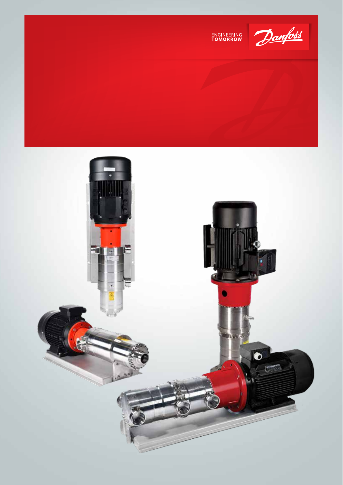
Energy Recovery Device
Energy Recovery Device
iSave 21 Plus / iSave 40
iSave 21-40
Body textBody textBody textBody text
www.danfoss.com
www.iSave.danfoss.com
hpp.danfoss.com

Data sheet | Energy Recovery Device | iSave 21 Plus and iSave 40
Table of Contents Contents
1. General information.....................................................................3
1.1 iSave 21 Plus ............................................................................3
1.2 iSave 40.................................................................................4
2. Benefits.................................................................................4
3. Technical data ..........................................................................5
3.1 iSave without motor ....................................................................5
3.2 iSave with IEC motor ....................................................................6
3.3 iSave with NEMA motor (can only be ordered through Danfoss US) .......................7
4. Flow at different rpm....................................................................8
5. Corrosion...............................................................................8
5.1 Operation...............................................................................8
6. Noise level..............................................................................9
7. Filtration................................................................................9
8. iSave drawings .........................................................................10
8.1 Assembled iSave 21 Plus and iSave 40 without electric motor ...........................10
8.2 Assembled iSave 21 Plus and iSave 40 with IEC electric motor ...........................12
8.3 Assembled iSave 21 Plus and iSave 40 with NEMA motor ................................18
9. Installation.............................................................................22
10. RO systems with an iSave...............................................................23
11. Performance curves....................................................................24
11.1 Performance and torque curves iSave 21 Plus ...........................................24
11.2 Performance and torque curves iSave 40................................................26
12. Service.................................................................................28
12.1 Warranty...............................................................................28
12.2 Maintenance...........................................................................28
12.3 R epair .................................................................................28
I
2
521B14 64 | DKCFN.PD.003.4B.02 | 2018 .05
Data sheet | Energy Recovery Device | iSave 21 Plus and iSave 40
1. General information
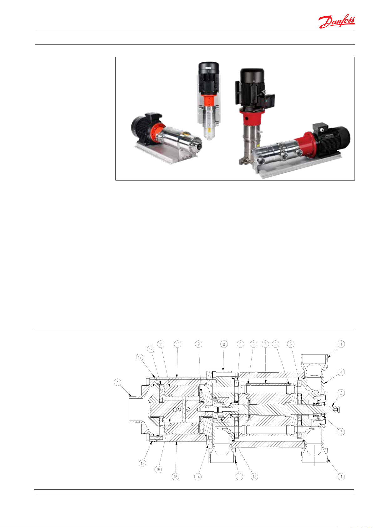
iSave 21 Plus
iSave 40
1. 2” Victaulic connections
2. Shaft
3. Low pressure shaft seal
4. Port flange
5. Port plate
6. Valve plate
7. Cylinder drum
8. Port flange
9. Port plate
10. Pins
11. Vane s
12. Port plate
13. Coupling
14. Adapter flange
15. Rotor
16. Stator
17. Port flange
18. Outlet flange
The iSave 21 Plus and iSave 40 consists of an
isobaric pressure exchanger, a high-pressure
positive displacement booster pump and an
electric motor.
The isobaric pressure exchangers are based on
the technology used in the Danfoss APP pumps,
and the high-pressure booster pumps are based
on the vane pump principle enabling a very light
and compact design. The design of iSave 21 Plus
and iSave 40 ensures lubrication of the moving
parts by the fluid itself.
All parts included in the iSave 21 Plus and iSave
40 are designed to provide long service life with
a constant high efficiency and minimum service
required.
1.1 iSave 21 Plus
The vane pumps are fixed displacement pumps
in which the flow is proportional to the number
of revolutions of the driving shaft – enabling flow
control.
The electric motor provides speed control of
both the pressure exchanger and the highpressure booster pump on the same shaft
– preventing overspin/overflushing.
The iSaves need a VFD that allows the motor to
apply a constant torque from low speed to
maximum speed.
The sectional drawings below illustrate the main
components of the iSave 21 Plus and iSave 40,
respectively
521B14 64 | DKCFN.PD.003.4B.02 | 2018 .05
3
Data sheet | Energy Recovery Device | iSave 21 Plus and iSave 40
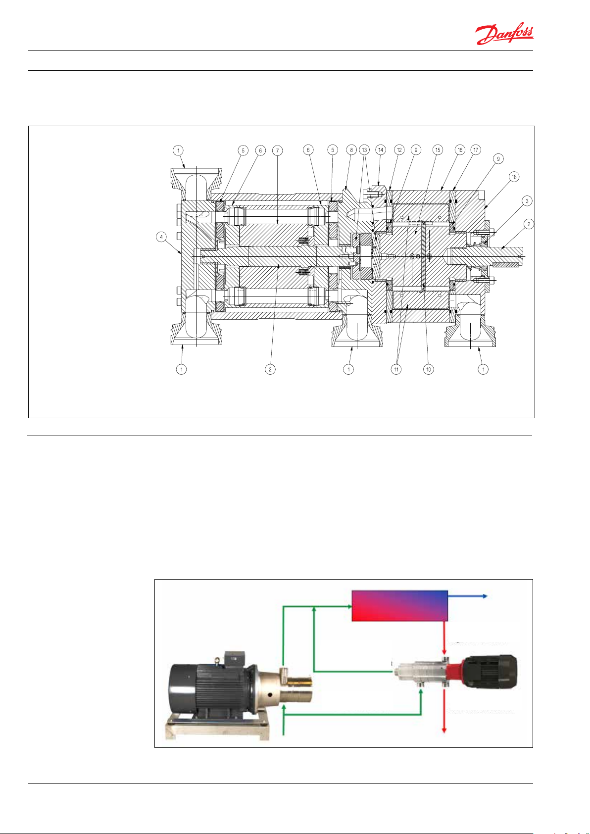
1.2 iSave 40
1. 3” Victaulic connections
2. Shaft
3. Low pressure shaft seal
4. Port flange
5. Port plate
6. Valve plate
7. Cylinder barrel
8. Port flange
9. Sealing plate
10. Pins
11. Vane s
12.Port plate
13. Coupling
14. Adapter flange
15. Rotor
16. Stator
17. Port plate
18. Outlet flange
2. Benefits
• One of the smallest and lightest energy recovery
devices on the market
• Few components
• High efficiency
• No need for high-pressure flow meters
• No expensive high-pressure mechanical seal
• No risk of over spin/over flushing
• Easy modular service
• All parts of the device are made of high
corrosion-resistant materials e.g. Super Duplex
(HP)
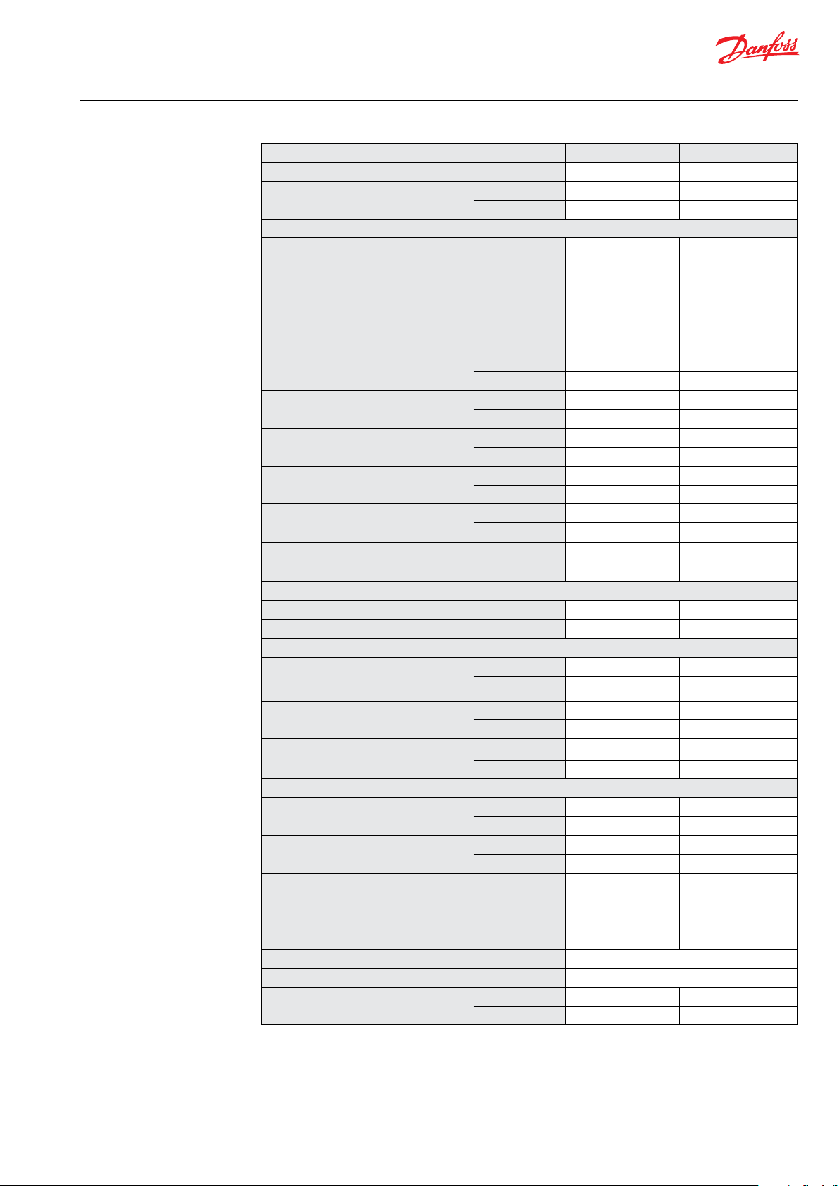
High-pressure outlet
(LP)
Low-pressure inlet
(HP)
High-pressure inlet
(LP)
Low-pressure outlet
4
521B14 64 | DKCFN.PD.003.4B.02 | 2018 .05
Data sheet | Energy Recovery Device | iSave 21 Plus and iSave 40
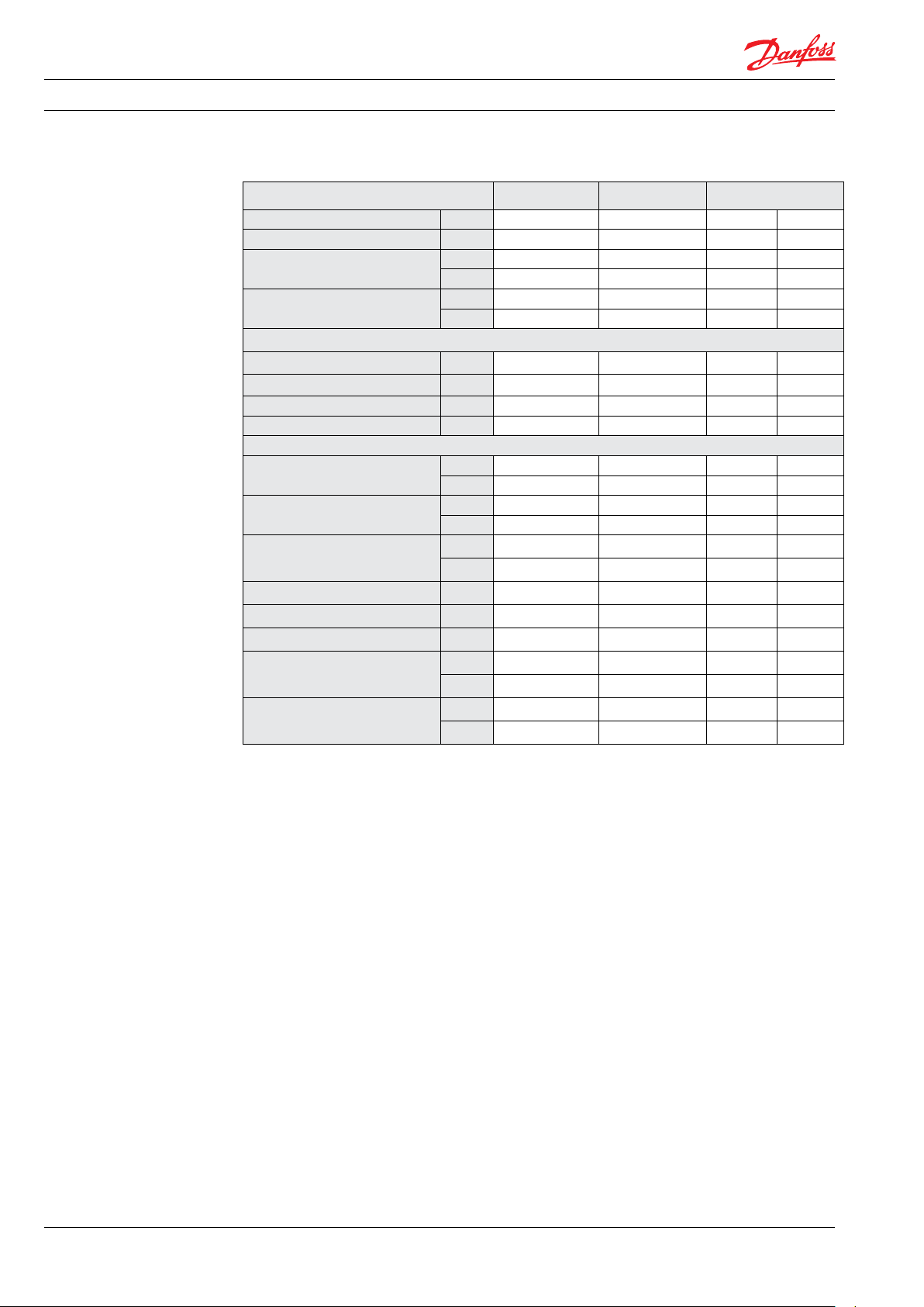
3. Technical data 3.1 iSave without motor
iSave size iSave 21 Plus iSave 40
Code number 180F7015 18 0F 7011
Geometric displacement
Pressure
Differential pressure HP in - HP out max.
HP max. outlet pressure
HP min. inlet pressure
HP max. inlet pressure
HP inlet min. pressure,
intermittent
2) 3)
LP inlet max. pressure
LP inlet max. pressure intermittent
LP outlet min. pressure
LP differential LP in - out at HP max. flow
Speed
Min. speed rpm 500 600
Max. speed rpm 1500 120 0
Typical flow
HP outlet flow range
4)
at max. differential pressure
Lubrication flow at 60 barg (871 psig) max.
LP inlet max. flow
Torque
Torque at max. differential pressure
operation
1)
Max. starting torque (stick/slip)
Media temperature
5)
Ambient temperature
Filtration requirements (nominal)
Salinity increase at membrane at 40% recover y rate 2-3 %
Weight
1)
Continuous torque a bove max. differential pre ssure
will reduce the lifetime of the iSave.
2)
Pressure can reach this pressure level at start-up
and permeate flush.
3)
Intermittent pressure is acceptable for less than 10
521B14 64 | DKCFN.PD.003.4B.02 | 2018 .05
1)
3)
6)
cm³/rev 273 626
In³/rev 16.7 38.2
bar 5 5
psi 72.5 72.5
barg 83 83
psig 120 0 120 0
barg 15 20
psig 217 290
barg 83 83
psig 120 0 120 0
barg 3 3
psig 44 44
barg 5 5
psig 72 72
barg 10 10
psig 145 145
barg 1 1
psig 14. 5 14.5
bar 0.9 1.2
psi 13 17.5
m³/h 6-22 21- 41
gpm 26-96 92-180 .5
m³/h 0.4 0.8
gpm 1.8 3.5
m³/h 33 67
gpm 145 295
Nm 49 102
lbf-ft 36 75
Nm 50 150
lbf-ft 37 110
o
C 2-40 2-40
o
F 36 -122 36 -122
o
C 0-50 0-50
o
F 32-104 32-10 4
3 micron melt-blow
kg 47 123
lb 103 271
minutes within a period of 6 hours.
4)
Typical average flow at 60 bar.
5)
Dependent on NaCI concentation.
6)
Please see section 7. filtration.
5
Data sheet | Energy Recovery Device | iSave 21 Plus and iSave 40
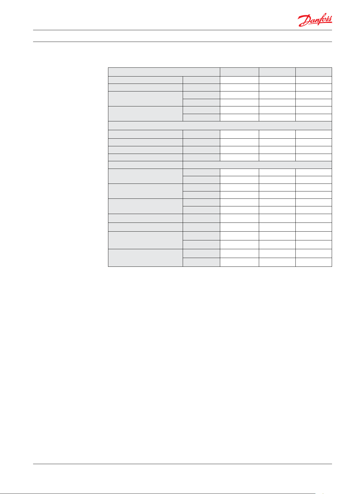
3.2 iSave with IEC motor
iSave iSave 21 Plus A)iSave 21 Plus iSave 40
Code number horizontal 180F7016 180F7017 180F7001 180F700 4
Code number vertical 180F7016 18 0F7017 180F7003 180F7005
Motor size IEC version IEC 400 V,
1)
50 Hz
Frame size
Motor data
Nominal speed rpm 1450 1450 970 970
Min. speed at 400 V rpm 500
Max. speed at 400 V rpm 1500 150 0
Rated current at 400 V A 11 15.2 22 30
Torque
Motor torque at norminal speed
Motor torque at min. speed
3)
Motor ambient temperature, max.
Motor insulation Class B B B B
Motor degrees of protection IP 55 55 55 55
Sound pressure level max.
6)
Weight
Footprint (horizontal/vertical)
kW 5.5 7.5 11 15
HP 7. 5 10 15 20
IEC 132 S 132 M 160 L 180 L
pole 4 4 6 6
Nm 36 49
3) 4)
lbf-ft 26.5 36 80 107.7
Nm 27 36 95 129
lbf-ft 20 27 70 95
o
C 40 40 40 40
o
F
dB(A) 78 79 84 84
kg 105 116 254 305
lb 231 255 560 672
m² 0.31 0.32 0.5/0.16 0.54/0.17
foot² 3.34 3.45 5.38/1.72 5.81/1.83
2)
500 600 600
3)
110 0 120 0
5)
108 14 6
12
2
122 122 12
2
A)
Differential pressure HP in - HP out max. is limited
to 3 bar [44 psi]
1)
Three-phase-asynchronous-motor according to
DIN-IEC and VDE 0530 standards.
• Voltage and frequency according to IEC 38
• The motors are fitted with a rating plate in
multi-tension: 380-420 V / 660-720 V, 50 Hz or
440-480 V, 60 Hz
• Tolerance ± 5% according to VDE 0530
• Standard coating according to IEC 60721-2-1
2)
If voltage is below 400 V we recommend to use
another size of electric motor.
Please contact Danfoss High Pressure Pumps for
further information.
3)
Torque load for iSave and motor see diagram on
page 23 and 25.
4)
Due to iner tia and stick-slip frictio n of the iSave, the
torque may exceed the maximum allowable
operation torque for the iSave when it is taken into
use and/ or speed is ramped up from zero to
maximum. A VFD or a soft starter must be used for
ramp up.
5)
The starting torque must not exceed the values
stated under “Max. starting torque (stick/slip)”. The
VFD must be able to deliver 140% start torque. The
Danfoss VFD type FC 301 and FC 302 can be used.
For advice on VFD settings, please consult our
relevant guideline or contact Danfoss.
6)
A-weighted sound pressure level at 1 meter from
the pump unit surfaces (reference box) acc. to EN
ISO 20361 section 6.2. The noise measurements are
performed acc. to EN ISO 3744:2010 on ERD with
motor (motor-pump unit) at max. pressure and
speed.
6
521B14 64 | DKCFN.PD.003.4B.02 | 2018 .05
Data sheet | Energy Recovery Device | iSave 21 Plus and iSave 40
3.3 iSave with NEMA motor (can only be ordered through Danfoss US)
iSave iSave 21 Plus A)iSave 21 Plus iSave 40
Code number horizontal 180U0013 180U0052 180U0012
Code number vertical 180U0013 180U0052 180U0002
Motor size NEMA version
1)
High efficiency 460 V, 60 Hz
Frame size
Motor data
Nominal speed rpm
Min. speed continuous at 400 V rpm 500 500 600
Max. speed continuous at 400 V rpm 150 0 1500 120 0
Motor rated current 460 V A 12.4 18 24.2
Torque
Motor torque
Motor torque at min. speed
at norminal speed
4)
Motor ambient temperature, max.
3,300 feet above sea level
Motor degrees of protection IP 55 55 55
Sound pressure level max.
6)
Weight
Footprint (horizontal/vertical)
A)
Differential pressure HP in - HP out max. is limited
to 3 bar [44 psi]
kW 7.5 11 15
HP 10 15 20
NEMA 215TC 254 286TC
pole 4 4 6
Nm 40 59.7 119
3) 4)
(lbf-ft) 29.4 44
Nm 20 31 95
(lbf-ft) 14. 7 23 70
o
C 40 40 40
o
(
F)
dB(A) 78 79
kg 152 206 324
(lb) 335 454 715
m² 0.38 0.45/0.16 0.65/0.23
foot² 4.09 4. 85/1.72 7.0/2.48
2)
1760 1765 117 5
122 122 122
*)
Tested with IEC motor
5)
88.2
*)
84
1)
Three-phase-asynchronous-motor according to
NEMA MG-1 and UL 1004-1 standards.
• Insulation class F, service factor 1.25.
• Fan-cooled TEFC (IC411). Voltage and frequency
according to NEMA MG-1 part 12.
• The motors are fitted with a rating plate 230 /
460 V, 60 Hz.
• Plus or minus 10% of rated voltage, with rated
frequency. Standard coating according to
motor supplier specifications.
2)
Max. speed for iSave 21 is 1500 rpm.
3)
Torque load for iSave and motor see diagramme on
page 23 and 25.
4)
Due to inertia and stick-slip friction of the iSave, the
torque may exceed the maximum allowable
operation torque for the iSave when it is taken into
use and/ or speed is ramped up from zero to
maximum. A VFD or a soft starter must be used for
ramp up.
5)
The starting torque must not exceed the values
stated under “Max. starting torque (stick/slip)”. The
VFD must be able to deliver 140% start torque. The
Danfoss VFD type FC 301 and FC 302 can be used.
For advice on VFD settings, please consult our
relevant guideline or contact Danfoss.
6)
A-weighted sound pressure level at 1 meter from
the pump unit surfaces (reference box) acc. to EN
ISO 20361 section 6.2. The noise measurements are
performed acc. to EN ISO 3744:2010 on ERD with
motor (motor-pump unit) at max. pressure and
speed.
521B14 64 | DKCFN.PD.003.4B.02 | 2018 .05
7
Data sheet | Energy Recovery Device | iSave 21 Plus and iSave 40
ppm
iSave 21 Plus
iSave 40
0
22
44
66
88
110
132
154
176
198
0
5
10
15
20
25
30
35
40
45
500 600 700 800 900 1000 1100 1200 1300 1400 1500
gpm
m3/h
rpm
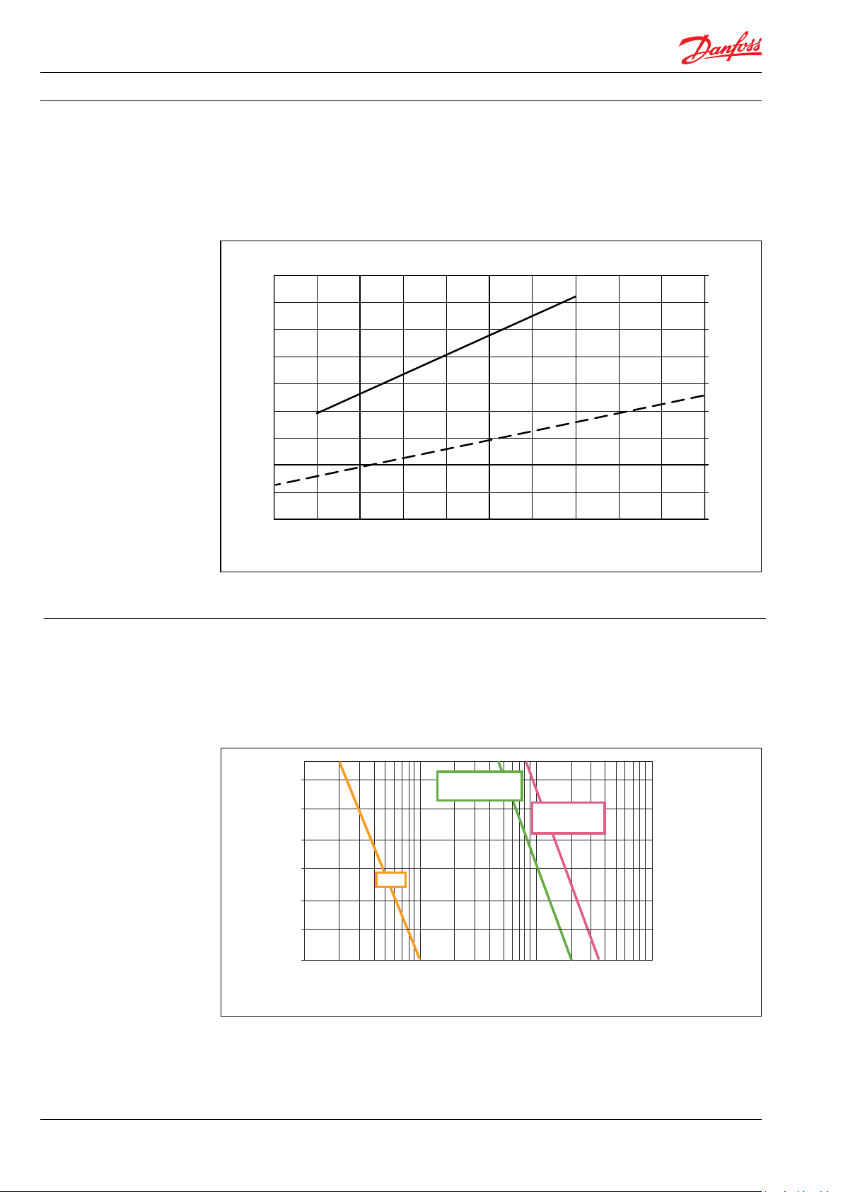
Flow at HP out vs. rpm
4. Flow at different rpm The diagram shows that the HP flow can be
changed by changing the rotation speed of the
iSave. The flow/rpm ratio is constant, the
required flow is obtainable by changing the
rotation speed to a required value.
For accurate data please use our selection tool
which is available on our website:
www.isave.danfoss.com
The iSave is delivered with a 3.1 performance
certificate according to EN10204.
5. Corrosion
5.1 Operation
The chart below illustrates the corrosive
resistance of different types of stainless steel
related to NaCl concentration and temperature.
All critical parts of the iSave is made of
Super Duplex 1.4410/UNS 32 750 or Duplex
1.4462/UNS 32803.
º
80
C
70
60
50
40
316L
30
20
100
160 1600
1000
Always flush the iSave with fresh water at
operation stop in order to minimize the risk of
crevice corrosion.
Duplex
Super Duplex
10 000
16000
100 000
160000
CI
ppm
NaCI
-
8
521B14 64 | DKCFN.PD.003.4B.02 | 2018 .05
Data sheet | Energy Recovery Device | iSave 21 Plus and iSave 40
6. Noise level The noise level for the iSaves is measured at max.
speed, a pressure of 80 barg and a booster
pressure of 5 bar. Since the iSave is mounted on a
bell housing and electric motor, the noise level
can only be determined for the complete unit
(system).
It is therefore important that a horizontal iSave
unit is mounted correctly on a frame with
dampeners to minimize vibrations and noise.
We recommend to mount a vertical iSave directly
to the floor with bolts. It is also strongly recommended to use high-pressure flexible hoses
between the hard piping in the RO-plant and the
iSave or to use multiple connections with
Victaulic clamps.
The noise level is influenced by:
Speed:
• High rpm makes more fluid/structure-borne
pulsations/vibrations than low rpm due to
higher frequency.
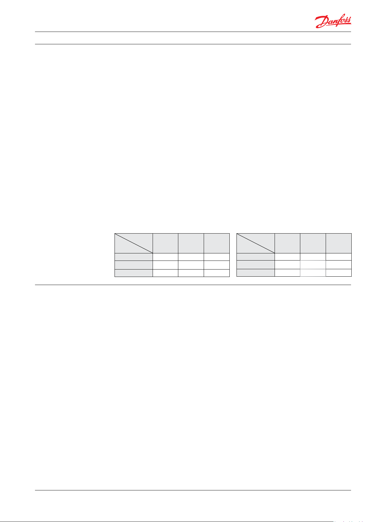
Noise level (dB(A) measured for the iSave 21 Plus and 40 at different speed and system pressure.
Booster pressure 3 bar.
iSave 21 Plus iSave 40
barg/psig
rpm
500 60 62 68
1000 69 72 74
150 0 77 78 78
20/290 60/870 80/1160
Pressure:
• High pressure makes more noise than low
pressure.
Mounting:
• Rigid mounting makes more noise than
flexible mounting due to structure-borne
vibrations.
Connections to iSave:
• Pipes connected directly to the iSave make
more noise than flexible hoses due to
structure-borne vibrations.
• Variable frequency drives (VFD):
Motors regulated by VFDs can increase noise
level if the VFD does not have the right
settings.
barg/psig
rpm
800 73 77 78
1000 76 79 81
120 0 78 82 84
30/435 60/870 80/1160
7. Filtration
It is important that the incoming water is filtered
properly to ensure optimum service life. A true
graded density, melt-blown depth filter cartridge
rated at 3 μm is therefore recommended.
It is important with selection of a proper filter
housing to ensure good cartridge end sealing.
If there is a high risk of water by-pass it is
recommended to use a second stage filter
solution.
As the various filters on the market differ greatly,
Danfoss High Pressure Pumps recommends
using cartridges with consistent, reliable
performance and high efficiency and where
fibres are blown continuously onto a central
support core. High Pressure Pumps does not
recommend cartridges requiring any type of
binders or resins.
Filters can be purchased from Danfoss
High Pressure Pumps. Please see section 10.0,
“RO systems with an iSave”, for installation of
filter. For more information on the importance of
proper filtration, please consult our publication
“Filtration” (code number 521B1009), which also
will provide you with an explanation of filtration
definitions and a guidance on how to select the
right filter.
521B14 64 | DKCFN.PD.003.4B.02 | 2018 .05
9
 Loading...