

isave.danfoss.com
Service instruction
Disassembling and assembling
iSave 21
MAKING MODERN LIVING POSSIBLE
Tel:+44(0)1706869777
E‐mail:sales@desal.co.uk
Web:www.desal.co.uk
Service instruction Disassembling and assembling iSave 21
2
180R9219 / 521B1171 / DKCFN.PI.0 03.K3.02 / 11.2013
1. General introduction....................................................................2
2. Disassembling the iSave.................................................................3
3. Disassembling the pressure exchanger ..................................................4
4. Assembling the pressure exchanger . . . . . . . . . . . . . . . . . . . . . . . . . . . . . . . . . . . . . . . . . . . . . . . . . . . . .6
5. Disassambling the vane pump..........................................................12
6. Assembling the vane pump ............................................................13
7. Assembling the iSave ..................................................................17
8. Exploded view vane pump ...................................................... 18
9. Exploded view pressure exchanger............................................... 19
10. Exploded view iSave ...................................................................20
Table of Contents
This document covers the instructions for
disassembling and assembling the iSave 21.
Important: It is essential that the iSave is
serviced in conditions of absolute cleanliness.
For a better understanding of the iSave, please
see the exploded view in item 8, 9 and 10.
The weight of the iSave is 65 kg / 143 lb
and it must be lifted with suitable lifting
equipment.
The weight of the pressure exchanger alone is
28 kg / 62 lb.
It is essential that the iSave is serviced in
conditions of absolute cleanliness
To prevent cold welding, lubricate threads of
screws with grease screw them into the component and tighten them by the hand. Use PTFE
lubrication type.
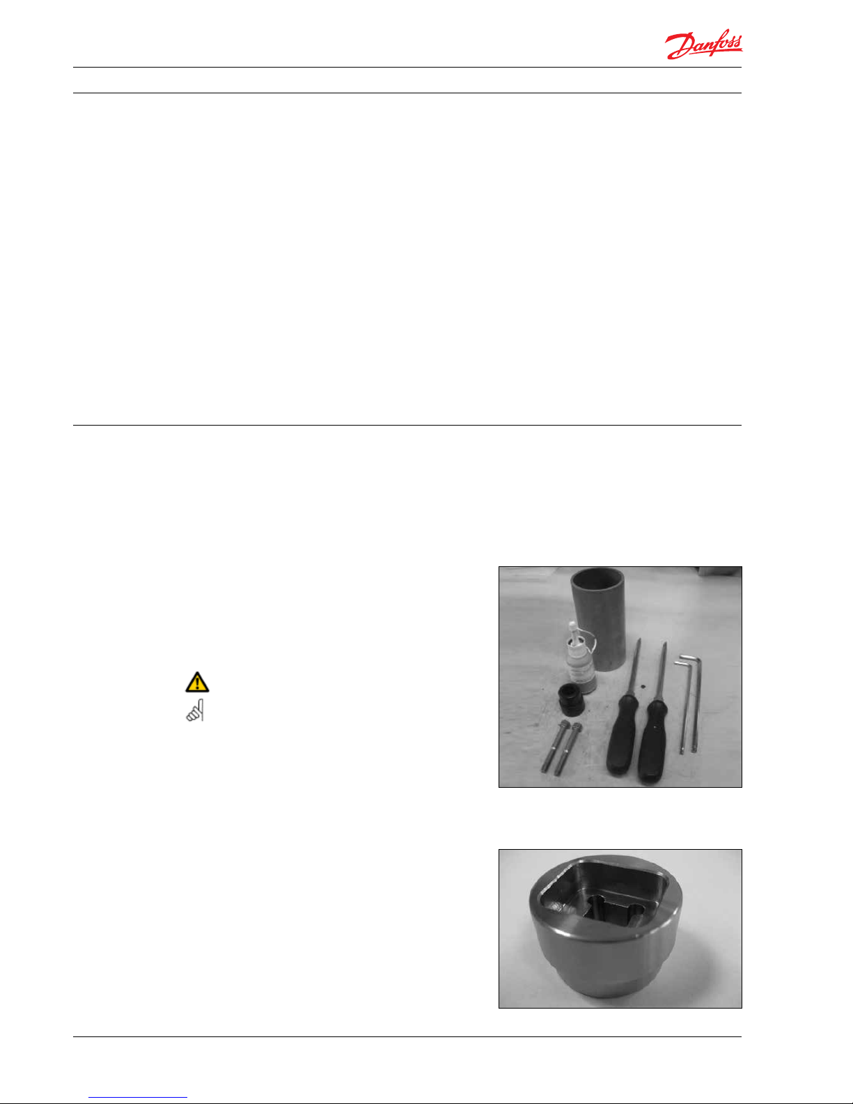
Tools needed for disassembling the iSave:
- 6 mm and 8 mm allen key
- 2 screwdrivers
- 2 M8 bolts
- Plastic tube
- Plastic tool for shaft seal assembly
- Loctite 270
Torque wrench with special socket
Code no. 180Z0610
1. General Introduction
Service instruction Disassembling and assembling iSave 21
3
180R9219 / 521B1171 / DKCFN.PI.0 03.K3.02 / 11.2013
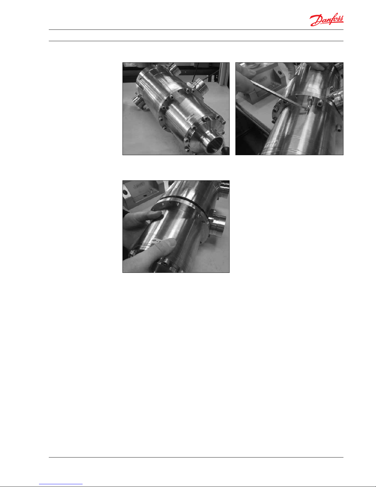
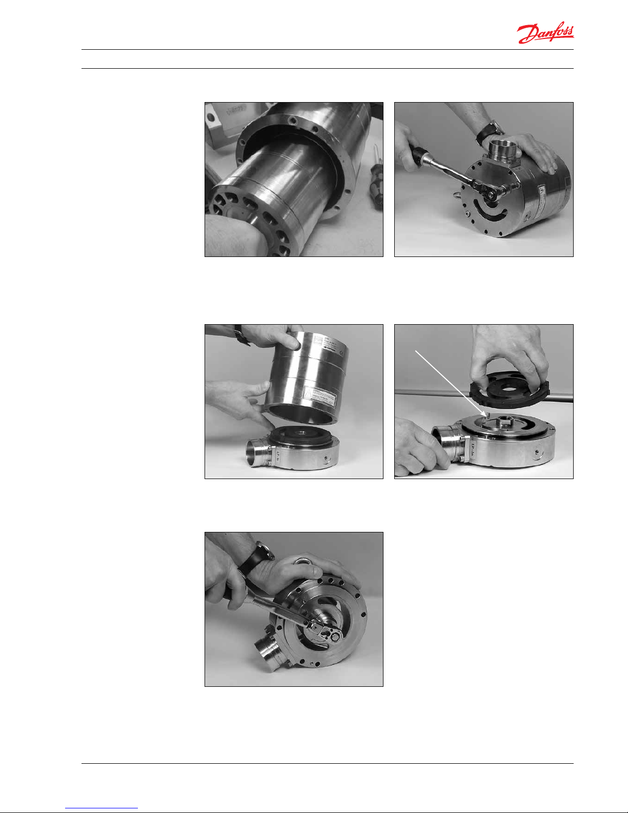
2. Disassembling
the iSave
1. Place the iSave on a clean table.
3. Remove the vane pump.
2. Unscrew the bolts in the ange.
Service instruction Disassembling and assembling iSave 21
4
180R9219 / 521B1171 / DKCFN.PI.0 03.K3.02 / 11.2013
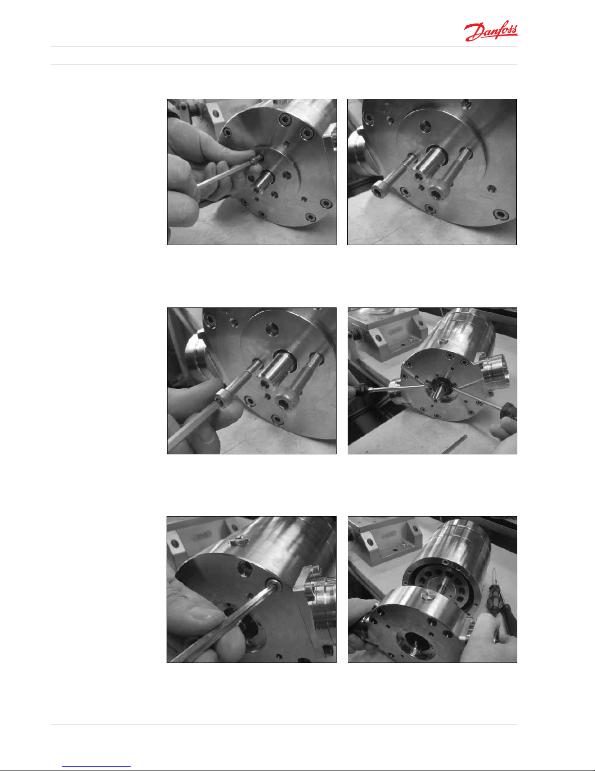
3. Disassembling the
pressure exchanger
1. Unscrew the bolts in the ange.
3. Gently push out the ange.
2. Screw in the two M8 bolts.
4. Wet the shaft and shaft seal with clean
ltered water. Gently lever the shaft
assembly free using 2 screwdrivers.
5. Unscrew the bolts in the ange. 6. Gently remove the ange.
Note: Loose parts on the inside of the ange.
Service instruction Disassembling and assembling iSave 21
5
180R9219 / 521B1171 / DKCFN.PI.0 03.K3.02 / 11.2013
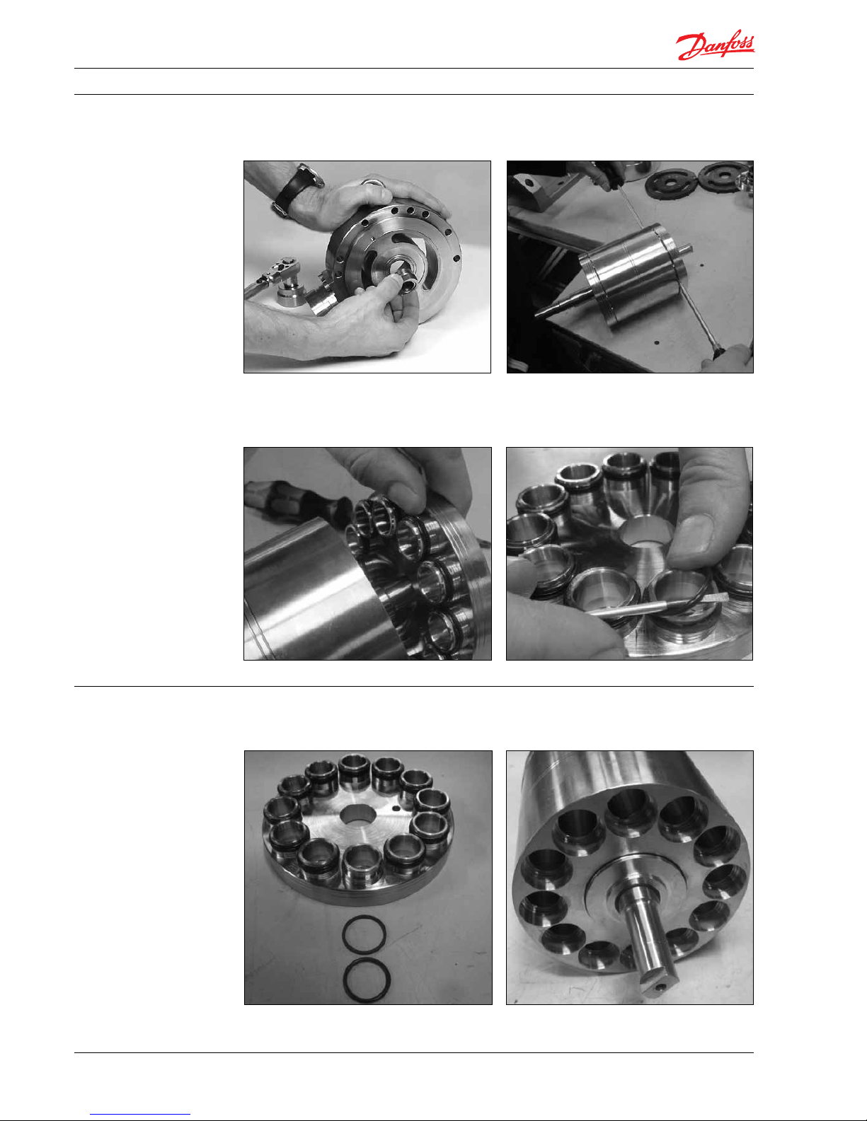
7. Gently remove the cylinder barrel.
9. Gently remove the housing.
Note: Loose parts on the inside of the ange.
8. Unscrew the bolts in the ange.
10. Remove port plate and pin.
Pin
11. Unscrew high-pressure bearing using a
special socket.
Service instruction Disassembling and assembling iSave 21
6
180R9219 / 521B1171 / DKCFN.PI.0 03.K3.02 / 11.2013
13. Remove the high-pressure bearing. 14. Gently lift the valve plate assembly free
with the aid of the screwdrivers.
15. Gently remove both valve plates. 16. Replace the O-rings and the back-up rings
on the valve plate.
4. Assembling the
pressure exchanger
2. Lubricate all the bores in the cylinder barrel
with grease and clean ltered water.
1. Mount the new back-up rings on the valve
plate rst and then the new O-rings.

Service instruction Disassembling and assembling iSave 21
7
180R9219 / 521B1171 / DKCFN.PI.0 03.K3.02 / 11.2013
18. Adjust the distance between the cylinder
drum and the secon d valve plate.
The distance must be about 4-6 mm.
This is not critical.
3. Gently press, by hand, the rst valve plate
onto the cylinder barrel.
Note: don’t scratch the valve plate when
placing it on the plastic tube.
4. Gently press, by hand, the second valve
plate onto the cylinder barrel by placing it
on the plastic tube.
Note: don’t scratch the valve plate when
placing it on the plastic tube.
The distance must be about 4-6 mm.
This is not critical.
5. Adjust the distance between the cylinder barrel
and the second valve plate (short shaft end).

Service instruction Disassembling and assembling iSave 21
8
180R9219 / 521B1171 / DKCFN.PI.0 03.K3.02 / 11.2013
7. Tighten the high-pressure bearing using
special socket and torque wrench with
70Nm±7
6. Mount the high-pressure bearing
8. Remove old O-ring with a new one 9. Position the housing over the guide pin
10. Mount all bolts in the ange and tighten
them all with 30Nm±3
11

Service instruction Disassembling and assembling iSave 21
9
180R9219 / 521B1171 / DKCFN.PI.0 03.K3.02 / 11.2013
11. Fit the guide pin in the ange.
13. Position the port plate over the guide pin.
Note: Make sure that the guide pin is located
in the locating hole in the port plate.
There are two dierent port plates in the iSave. One of them can be mounted on both anges in
the pressure exchanger. Make sure that they are assembled on the right ange.
12. Location hole in port plate.
14. Gently guide the cylinder barrel into the
bearing in the ange.
16. Wrong! large center hole.15. Check the next port plate is correct.
Correct small
center hole
Wrong! large
center hole

Service instruction Disassembling and assembling iSave 21
10
180R9219 / 521B1171 / DKCFN.PI.0 03.K3.02 / 11.2013
21. Mount all bolts in the ange and tighten
them to a torque of 30 Nm ± 3 Nm.
20. Position the port ange over the guide pin.
22. Wet the shaft seal with clean ltered water.
Do not use silicone grease.
Fit the shaft seal with the carbon surface upward.
17. Position the port plate over the guide pin.
19. Change the O-ring in the ange and
position the guide pin.
O-ring
Guide pin
18 Check that the port plate ts the center
bearing and the guide pin.

Service instruction Disassembling and assembling iSave 21
11
180R9219 / 521B1171 / DKCFN.PI.0 03.K3.02 / 11.2013
23. Shaft seal NOT mounted correct.
The rubber seal face must turn into the ange.
25. Shaft seal in right position:
24. Using the plastic assembly tool provided,
large diameter rst, press the seal home
against the shoulder, by hand.
Be careful not to damage the carbon seal face
on the shaft seal.
26. Remove the old ceramic ring from the
ange. Position the O-ring on the seal ange.
27. Push the new ceramic ring into the ange
using plastic tool provided. Make sure the
face with the rubber seal is positioned
against the shoulder in the ange.
Before assembly wet the parts with clean
ltered water.
28. Position the ange and the bolts. Tighten
the 4 bolts with 12 Nm ±1.2 N m.

Service instruction Disassembling and assembling iSave 21
12
180R9219 / 521B1171 / DKCFN.PI.0 03.K3.02 / 11.2013
1. Gently adjust the spanner wrench around
the coupling and use it as back stop.
3. Remove all bolts in the HP out connection
ange.
2. Unscrew the bolt in the middle of the
coupling and remove the coupling.
4. Remove the ange.
5. Disassambling the
vane pump
5. Remove side plate and pin

Service instruction Disassembling and assembling iSave 21
13
180R9219 / 521B1171 / DKCFN.PI.0 03.K3.02 / 11.2013
7. Gently remove the rotor.
Note: Loose parts inside the rotor.
6. Side plate removed.
8. Remove vanes.
1. Position the guide pin.
9. Gently remove side plate.
2. Location hole in the side plate:
6. Assembling the
vane pump

Service instruction Disassembling and assembling iSave 21
14
180R9219 / 521B1171 / DKCFN.PI.0 03.K3.02 / 11.2013
4. Place the 4 pins in the rotor.3. Position the side plate over the guide pin.
Note: Make sure that the guide pin is located
in the locating hole in the port plate. See #2
5. Gently place the rotor in the bearing.
7. Check that all vanes are positioned
correctly.
6. Position the 8 vanes in the rotor.
The pins may be moved by using a
screwdriver.

Service instruction Disassembling and assembling iSave 21
15
180R9219 / 521B1171 / DKCFN.PI.0 03.K3.02 / 11.2013
10. Position the side plate over the guide pin.
9. Replace the O-ring on the ange and wet
the ange properly with clean ltered water.
11. Make sure that the guide pin is located in the
locating hole in the side plate. See #10.
13. Make sure that the guide pin is located in
the location hole.
12. Fit the ange into both the bearing in the
ange and the location pin in the stator.
8. One vane is NOT positioned correctly.

Service instruction Disassembling and assembling iSave 21
16
180R9219 / 521B1171 / DKCFN.PI.0 03.K3.02 / 11.2013
14. Change the O-ring in the HP out
connection ange.
16. Fit the coupling into the pump.
Glue the threat on the bolt with “Loctite
270” and tighten the bolt with 10 Nm±1 Nm.
17. Change the two O-rings in the ange.
15. Bolt the ange onto the vane pump.
Tighten the bolt with 30 Nm ±3 Nm.

Service instruction Disassembling and assembling iSave 21
17
180R9219 / 521B1171 / DKCFN.PI.0 03.K3.02 / 11.2013
1. Fit the steel coupling onto the shaft of the
pressure exchanger.
3. Orient both the steel coupling and the
2 guide holes on the vane pump to t into
the pressure exchanger.
2. Fit the polymer coupling on the steel
coupling.
4. Mount the bolts into the ange and tighten
them with 30 Nm ±3 Nm.
7. Assembling the
iSave

Service instruction Disassembling and assembling iSave 21
18
180R9219 / 521B1171 / DKCFN.PI.0 03.K3.02 / 11.2013
8. Exploded view
vane pump

Service instruction Disassembling and assembling iSave 21
19
180R9219 / 521B1171 / DKCFN.PI.0 03.K3.02 / 11.2013
9. Exploded view
pressure exchanger

Service instruction Disassembling and assembling iSave 21
20
180R9219 / 521B1171 / DKCFN.PI.0 03.K3.02 / 11.2013
10. Exploded view iSave

Service instruction Disassembling and assembling iSave 21
21
180R9219 / 521B1171 / DKCFN.PI.0 03.K3.02 / 11.2013

Service instruction Disassembling and assembling iSave 21
22
180R9219 / 521B1171 / DKCFN.PI.0 03.K3.02 / 11.2013
Danfoss ca n accept no responsi bility for poss ible errors in ca talogues, bro chures and other pr inted material. D anfoss reserve s the right to alter it s products wit hout notice.
This also ap plies to produc ts already on orde r provided that su ch alterations ca n be made without su bsequential cha nges being nece ssary in speci cations alread y agreed.
All trade marks in this mater ial are proper ty of the respec tive companies . Danfoss and the Danf oss logotyp e are trademark s of Danfoss A/S. Al l rights reser ved.
Danfoss A/S
High Pressure Pumps
DK-6430 Nordborg
Denmark
 Loading...