

Design guide
Energy Recovery Device
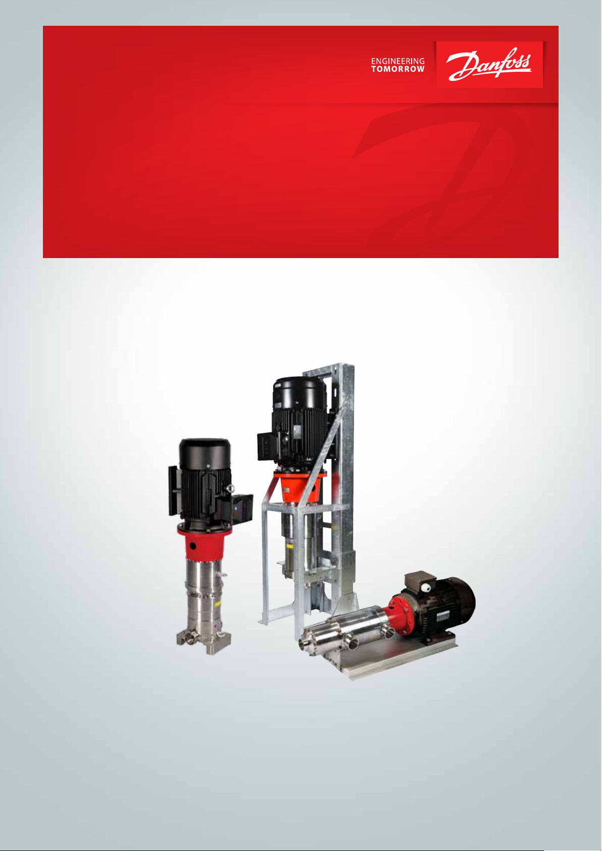
iSave
Membrane cleaning of RO-system
hpp.danfoss.com

Design guide Membrane cleaning of the RO-system with iSave ERD
Table of Contents Membrane cleaning ................................................................................................................................................................. 3
Starting up the system ............................................................................................................................................................ 4
Starting up the system ............................................................................................................................................................ 5
2
180R9214 / 521B1165 / DKCFN.PI.003.G6.02 / 09.2017

Design guide Membrane cleaning of the RO-system with iSave ERD
Below procedures are general guidelines for
the membrane cleaning of SWRO-systems with
the Danfoss iSave. Procedure details may differ
depending on the system design.
The numbers marked in () refer to the
diagram’s below.
The purpose of membrane cleaning is to reduce
scaling and fouling in the membranes. For optimal performance specific chemicals are required,
depending on the cause of the contamination.
After chemical treatment the system must be
flushed with fresh water. The flushing water,
coming out of the membranes, may consist of a
large amount of suspended inorganic particles. It
is important to assure that these particles are not
fed into the iSave(s) or pump(s).
NB! It is recommended to disconnect the
piping from the “HP in” of the iSave and flush
the contaminated water from the membranes
directly to drain. By disconnecting the pipes
there will be no accumulation of
contaminations in the HP-piping and
HP-valves. See P&ID no 2.
Membrane cleaning
The procedures below are based on Dow’s
Cleaning and Sanitization: Cleaning steps
described in Dow’s Form No. 609-02090-1005.
Other procedure may be used depending on the
membranes used.
Below procedure is according P&ID no 1.
1. Stop the high-pressure pump(s) (4), and stop
the iSave(s) (11).
2. Stop the seawater supply pump (A).
3. Close valve (9 and 27) and open valve (16 and
28), and feed cleaning solution through valve
(7).
4. Pump mixed cleaning solutions to the vessel
at conditions of low flow rate and low pressure
to displace the process water. Use only
enough pressure to compensate for the
pressure drop from feed to concentrate.
The pressure should be low enough that
essentially no or little permeate is produced.
A low pressure minimizes re-deposition of
dirt on the membrane. Dump the brine/
concentrate to prevent dilution of the
cleaning solution.
180R9214 / 521B1165 / DKCFN.PI.003.G6.02 / 09.2017
5. Recycle: After the process water is displaced,
cleaning solution will be present in the
concentrate/ brine stream. Recycle the
cleaning solution from the piping to the
cleaning solution tank.
6. Turn of the pump and allow the elements
to soak.
3

Design guide Membrane cleaning of the RO-system with iSave ERD
7. Feed the cleaning solution at high flow into
the “full flow cleaning” adapter (7). The high
flow rate flushes out the foulants removed
from the membrane surface by the cleaning.
8. Flush RO permeate or deionised water into
the “full flow cleaning” adapter (7).
Flush out the cleaning solution.
It is essential that the water used for the final
pre-flush is pre-filtered to a level described
in the datasheet.
P&ID no. 1
4
2
26
Media filter
A
B C
Filter
3 micron
nominel
PI
Fresh water
permeate flush
10 micron
absolut
PI
F
*
PI
PS
21
24
19
3
Filter
PI
PS
F
1
12
LP in
HP out
11
iSave
HP in
M
VFD
23 23
4
26
9. Open valve (9) and continue flushing.
The iSave(s) may start to rotate backward –
this is OK.
10. When flushing is finalised – assure that no
foulants remain in the piping or valve (9).
11. Close the high pressure “full flow cleaning”
valve (7) and close valve (16 and 28).
12. Open valve (27)
VFD
22
M
25
18
M
25
18
HP out
HP in
M
VFD
VFD
22
5
PI
6
PS
Flowmeter
Full flow
cleaning/CIP
7
1011
9
PI
13
14
PS
PI
15
20
F
8
16
28
27
Drain
17
Permeate
F
CIP
*
Second stage filter: If recommended housing design an d cartridges are not used, a second stage filter is required
Below procedure is according P&ID no 2.
1. Stop the high-pressure pump(s) (4), and stop
the iSave (11).
2. Stop the seawater supply pump (A).
3. Disconnect pipe in joint (9) and connect the
pipe to low pressure “Full flow cleaning”
joint (16).
4. Plug pipe in joint (9).
5. Close valve (27) and open valve (28)
6. Pump mixed cleaning solutions through valve
(7) to the vessel at conditions of low flow rate
and low pressure to displace the process
water. Use only enough pressure to
compensate for the pressure drop from feed
to concentrate.
The pressure should be low enough that
essentially no or little permeate is produced.
A low pressure minimizes re-deposition of dirt
on the membrane. Dump the brine/
concentrate to prevent dilution of the
cleaning solution.
7. Recycle: After the process water is displaced,
cleaning solution will be present in the
concentrate stream. Recycle the cleaning
solution from the piping to the cleaning
solution tank.
8. Turn of the pump and allow the elements to
soak.
9. Feed the cleaning solution at high flow into
the “full flow cleaning” adapter (7) on the
feed side of the membrane. The high flow rate
flushes out the foulants removed from the
membrane surface by the cleaning.
4
180R9214 / 521B1165 / DKCFN.PI.003.G6.02 / 09.2017

Design guide Membrane cleaning of the RO-system with iSave ERD
P&ID no. 2
10. Flush RO permeate or deionised water into
the “full flow cleaning” adapter (7) on the
feed side of the membrane. Flush out the
cleaning solution.
It is essential that the water used for the final
pre-flush is pre-filtered to a level described in
the datasheet.
M
4
2
26
Media filter
A
B C
Filter
3 micron
nominel
PI
PI
*
PI
PS
21
Fresh water
permeate flush
24
19
3
Filter
PI
10 micron
PS
absolut
F
1
F
12
LP in
HP out
11
HP in
M
VFD
23 23
26
iSave
18
M
4
18
M
VFD
11. When flushing is finalised – Close the high
pressure “full flow cleaning” valve (7) and
close valve (28).
12. Connect the high pressure pipe to joint (9)
again.
VFD
22
VFD
25
25
HP out
HP in
5
PI
PS
22
6
Full flow
cleaning/CIP
7
1011
PI
9
13
15
20
PS14PI
F
Flowmeter
8
16
Drain
17
Permeate
F
28
CIP
v
27
*
Second stage filter: If recommended housing design and car tridges are not used, a second stage filter is required
VFD
22
M
4
2
26
Media filter
A
B C
Filter
3 micron
nominel
PI
PI
*
PI
PS
21
Fresh water
permeate flush
24
19
*
Second stage filter: If recommended housing design and car tridges are not used, a second stage filter is required
3
Filter
PI
10 micron
PS
absolut
F
1
F
12
LP in
HP out
11
HP in
M
VFD
23 23
4
26
iSave
25
18
M
25
18
HP out
HP in
M
VFD
VFD
22
5
PI
6
PS
Full flow
cleaning/CIP
7
1011
PI
9
13
15
20
PS14PI
F
Flowmeter
8
16
Drain
17
Permeate
F
28
CIP
27
180R9214 / 521B1165 / DKCFN.PI.003.G6.02 / 09.2017
5

Danfoss A/S
High Pressure Pumps
Nordborgvej 81
SK-6430 Nordborg
Denmark
© Danfoss | DCS (im) | 2017.09
521B1165 | DKCFN.PI.00.G6.02 | 6
 Loading...