

Page 1
User Guide
Intelligent Purging System (IPS 8)
Ammonia
230 V AC, 60 Hz
Info for UK customers only
Danfoss Ltd. Oxford Road, UB9
4LH Denham, UK
Other IPS 8 User Guide languages
ir.danfoss.com
ir.danfoss.com148R9653
Page 2

User Guide | Intelligent Purging System (IPS 8) Ammonia
Contents
Legal notice ...................................................................................................................................................................................................................3
Technical data ..............................................................................................................................................................................................................4
Ordering ..........................................................................................................................................................................................................................4
Introduction ..................................................................................................................................................................................................................5
Features ...........................................................................................................................................................................................................................5
Working principle .....................................................................................................................................................................................................6
Working cycle ..............................................................................................................................................................................................................7
Air traps ............................................................................................................................................................................................................................8
Connection locations ..............................................................................................................................................................................................9
Connection points ................................................................................................................................................................................................. 11
Installation ..................................................................................................................................................................................................................12
Electrical wiring ...................................................................................................................................................................................................... 14
Light Indicators ........................................................................................................................................................................................................ 16
Quick Startup ............................................................................................................................................................................................................ 17
General display.........................................................................................................................................................................................................17
Configuring using the LCD ...............................................................................................................................................................................18
Modbus RTU .............................................................................................................................................................................................................. 20
Maintenance/Service/Disposal ......................................................................................................................................................................27
2 | BC344024774466en-000401
© Danfoss | DCS (ms) | 2021.04
Page 3
User Guide | Intelligent Purging System (IPS 8) Ammonia
Legal notice This product information is a part of the documentation for the Danfoss scope of delivery and serves
as product presentation and customer advisory service. It contains important information and
technical data regarding the product.
This product information should be supplemented with the information about the industrial safety
and health related regulations at the site of installation of the product. The regulations vary from
place to place as a result of the statutory regulations applicable at the site of installation and are
therefore not considered in this product information.
In addition to this product information and the accident prevention regulations applicable for the
respective country and area where the product is used, the technical regulations for safe and
professional work must also be observed.
This product information has been written in good faith. However, Danfoss cannot be held responsible
for any errors that this document may contain or for their consequences.
Danfoss reserves the right to make technical changes during the course of further development of the
equipment covered by this product information.
Illustrations and drawings in this product information are simplified representations. As a result of
the improvements and changes, it is possible that the illustrations do not exactly match the current
development status. The technical data and dimensions are subject to change. No claims will be
accepted on the basis of them.
Danfoss A/S
6430 Nordborg
Denmark
CVR nr.: 20 16 57 15
Telephone: +45 7488 2222
Fax: +45 7449 0949
EU DECLARATION OF CONFORMITY
declares under our sole responsibility that the
Product category: Intelligent Purger System (Air Purger)
Type designation(s): IPS 8
Covered by this declaration is in conformity with the following directive(s), standard(s) or other normative
document(s), provided that the product is used in accordance with our instructions.
Machine Directive 2006/42/EC
EN 378-2:2016 Refrigerating systems and heat pumps - Safety and environmental requirements - Part 2: Design,
construction, testing, marking and documentation
IEC 60204-1:2018 Safety requirements for electrical equipment for measurement, control and laboratory use - Part 1:
General requirements
Pressure Equipment Directive 2014/68/EU (PED)
EN 378-2:2016 Refrigerating systems and heat pumps - Safety and environmental requirements - Part 2: Design,
construction, testing, marking and documentation
Ammonia side (R717): Category A4P3. Fluid group: 1. PS = 40 bar. TS: -40 C to 60 C
R452A side: Category 1. Fluid group: 2. PS = 28 bar. TS: -40 C to 60 C
Ambient temperature: -10 C to 43 C
Electromagnetic Compatibility Directive 2014/30/EU (EMC)
IEC 61000-6-2 Electromagnetic compatibility (EMC) - Part 6-2: Generic standards - Immunity standard for industrial
environments (IEC77/488/CDV:2015)
EN 61000-6-4 Electromagnetic compatibiliy (EMC) - Part 6-4: Generic standards - Emission standard for industrial
environments
Note: EMC test performed with cable length < 30m.
Date: YYYY.MM.DD
Place of issue:
Signature:
Danfoss only vouches for the correctness of the English version of this declaration. In the event of the declaration being translated into any other
language, the translator concerned shall be liable for the correctness of the translation
ID No: 084R9456
This doc. is managed by 500B0577
Issued by
Name: Su Cheong Ho
Title: Lead Design Engineer
Refrigeration & Air Conditioning Controls
Revision No: AA
Danfoss A/S
Date: YYYY.MM.DD
Place of issue:
Signature:
Approved by
Name: Behzad Parastar
Title: Product Manager
Page
1 of
1
© Danfoss | DCS (ms) | 2021.04
BC344024774466en-000401 | 3
Page 4
User Guide | Intelligent Purging System (IPS 8) Ammonia
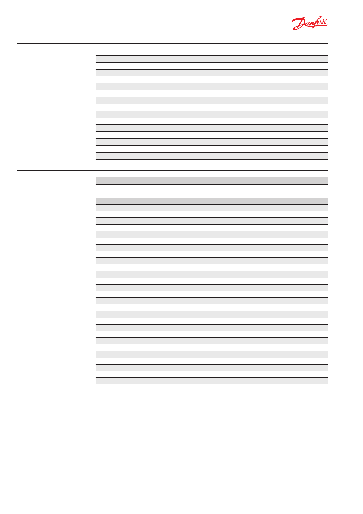
Technical data
Ordering
Supply voltage 230V AC, 1ph, 60Hz
Current 5.7 A (max. 6.5 A)
Power consumption max. 1.3 kW
Short-circuit current rating Icc 10kA
Temperature range ambient -10 °C to +43 °C (14 °F to 109 °F)
Temperature range transport/storage -30 °C to +60 °C (-22 °F to 140 °F)
Enclosure IP55
Weight max. 100 kg (221 lbs)
Dimensions (LxWxH) 1051 x 441 x 703 mm (41.4 x 17.4 x 27.7 inches)
Purger refrigerant R452A 900 gram (31.7 oz)
Max. operating pressure (PS) R452A 28 bar (406 psi)
System refrigerant R717
Min. operating pressure R717 6.5 bar (94 psi)
Max. operating pressure R717 40 bar (580 psi)
Operating temperature R717 -40 °C to +60 °C (-40 °F to 140 °F)
Unit
Danfoss Intelligent Purging System IPS 8 60Hz unit 084H5002
Accessories/Spare parts Accessory Spare part Code
Flange blind blank incl Bolts, nuts and Gaskets* x 084H5053
SV3 Float Valve x 027B2023
ICF 15-4 solenoid, DIN Butt weld 15mm ½ inch x 027L4543
ICF 15-4 solenoid, ANSI Socket weld 15mm ½ inch x 027L4538
ICF 15-4 solenoid, ANSI Butt weld 15mm ½ inch x 027L4602
Welding Flange incl Bolts, nuts and Gaskets x 084H5061
Purger solenoid kit (Armature, tube, Sealing, Orifice, Filter insert) x 084H5051
Solenoid coil, 24V DC for AKV x x 018F6757
PSU, 24V DC - optional for powering purge points x x 080Z0055
Restrictor, purge line x 084H5054
Compressor Cranck case heater x 084H5058
Condenser coil assy incl screws x 084H5059
Fan motor for condenser Incl fan grid and screws x 084H5060
Extraction Fan x 084H5056
Air grid with filter (1 piece) x 084H5057
Pre-programmed MCX 15 x 084H5052
Pressure transmitter evaporator, soldered (AKS 32R) x 060G3552
Compressor including Start relay box and Start and Run Capacitor x 123B2156
Compressor Hi-temp sensor x 084N2003
Expansion valve, R452A x 068U3881
Sight glass x 014-0191
Pressure transmitter - R717, Threaded, AKS2050 x 060G5750
Thermostat for crankcase heater control x 060L111166
Temperature sensor - R717, AKS 21M x 084N2003
Pressure switch for Fan x Contact Danfoss
Pressure safety switch x Contact Danfoss
* For closing system flange during system pressure testing
Code number
4 | BC344024774466en-000401
Note:
All Spare part items are parts already built into
the IPS 8 All accessories are not.
© Danfoss | DCS (ms) | 2021.04
Page 5

User Guide | Intelligent Purging System (IPS 8) Ammonia
Introduction
The Danfoss Intelligent Purging System (IPS 8)
is a stand-alone, self-contained purging unit
designed to remove non-condensable gases
(NC gases = air and other unwanted foreign
gases) from industrial ammonia refrigeration
systems.
The IPS control can handle up to 8 purge points
automatically.
The ingress of NC gases into a refrigeration
system is inevitable, regardless of the refrigerant,
pressures, or temperatures. NC gases in the
system will result in a decrease in system
efficiency, both in terms of an increase in power
consumption and reduced cooling capacity.
Due to having a different density than ammonia,
the ingressed air will accumulate in specific areas
of the system, where it can be removed using the
Danfoss IPS 8.
The accumulation areas are identified in the
Connection locations section, along with
recommended connection principles.
The purger unit is an electronically controlled,
self-contained R452A refrigerant system that runs
independent of the main ammonia system and
with only one flange connection to the ammonia
plant.
The flanged opening allows the ammonia gas/
NC gas mix access to the purger’s heat exchanger,
where it is split into ammonia condensate and NC
gases. The ammonia condensate is returned by
gravity to the main plant, while the NC gases are
purged to the atmosphere through e.g. a water
bath.
Through the flanged opening, the purger unit
has access to the parameters from the ammonia
plant required for full electronic control.
The unit runs automatically in 24-hour cycles,
checking for the presence of NC gases and, if
present, removes the NC gases.
To regain and retain the design capacity of the
main ammonia system and prevent future air
accumulation, it is highly recommended to install
the Danfoss IPS 8.
Features
• State-of-the-art electronically controlled unit
based on the Danfoss MCX controller platform
• Reduced power consumption of the ammonia
plant
• Automatic purging response to NC gases in the
refrigeration system
• Continuous and smart monitoring of
differential pressure between the system
refrigerant and the purger’s refrigerant
• Smart purging that minimizes refrigerant
(ammonia) release to the environment
• Self-contained unit operation, which functions
independently from the main plant
• An operation log for easy purging cycle data
monitoring
• Industry standard Modbus RTU
communication for remote monitoring and
system integration
• Reduced purging unit power consumption
compared to other units due to on-demand
operation only
• Self-diagnostics for both unit and system
operation to shut down in the event of
malfunctions
• Cost-effective installation with few mechanical
and electrical connections
• A fully brazed and leak-tested R452A cooling
system, minimizing leakage risks
• A plug-and-play stand-alone design, which
simplifies installation and commissioning while
reducing potential errors
• No need for advanced settings
• A compact and easy-to-handle design
• Patent pending on IPS 8
© Danfoss | DCS (ms) | 2021.04
BC344024774466en-000401 | 5
Page 6
User Guide | Intelligent Purging System (IPS 8) Ammonia
13
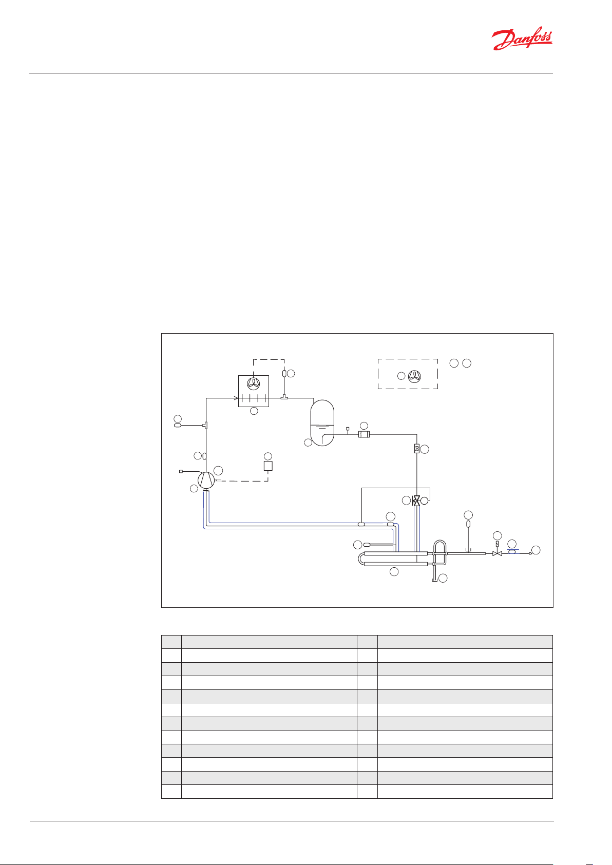
Working principle The Danfoss IPS 8 is factory-tested and ready to
use in ammonia plants with a condenser pressure
of more than 6,5 bar (94 psi). The purger is
charged with 900 gram (31.7 oz) of R452A.
Only 2 mechanical connections are needed for
the purger (see fig. 1). The flow of ammonia/NC
gases from the main plant is done through the
flange for ammonia (see 13 in Fig. 1 below), while
the NC gas purge is done through the blow-off
pipe after the purge restrictor (18).
Through the flange for ammonia (13), a mixture
of ammonia gas and NC gases enters the heat
exchanger (12) part of the purger.
The ammonia gas/NC gas mix is cooled down
below the condensing temperature of the
ammonia by the R452A circuit. At this point,
ammonia gas condenses and returns by gravity
to the ammonia plant whereas the NC gases
accumulate in the heat exchanger (12) for
subsequent purging.
7
By condensing the ammonia gas, a new
ammonia/NC gases mix is naturally pulled
through. This new mix is separated through a
continuous process.
As the NC gas concentration in the heat
exchanger (12) increases, the R452A heat
exchanger pressure and temperature will
simultaneously decrease.
The controller continuously monitors the R452A
heat exchanger pressure as well as ammonia
pressure and temperature. When the R452A
pressure reaches a predefined pressure difference
when compared with the ammonia pressure
(temperature) it prepares to purge the NC gases
through the solenoid valve (16). The blow-off
is activated by the solenoid (16) and through
appropriate piping/hosing, should be led into
a water bath. This process is recommended
to retain small amounts of ammonia (see
Installation section).
19 20
6
4
3
1a
1
Fig. 1 - Purger R452A lay-out
1 Compressor R452A 11 Expansion valve, R452A
1a Compressor Cranck case heater 12 Heat exchanger Ammonia/R452A
2 Thermostat for crankcase heater control 13 Welding Flange
3 Discharge temp sensor R452A 14 Pressure transmitter R452A
3a Suction temperature sensor R452A 15 Pressure transmitter R717
4 Pressure safety switch 16 Solenoid valve AKVA and coil
5 Condenser 17 NC temperature sensor R717
6 Extraction fan 18 Restrictor, purge line
7 Pressure switch for Fan 19 MCX 15 (Pre-programmed)
8 Receiver 20 PSU, 24V
9 Filter 900 gram (31.7 oz) R452A
10 Sight glass
5
9
8
2
3a
14
10
11
12
15
16
17
18
6 | BC344024774466en-000401
© Danfoss | DCS (ms) | 2021.04
Page 7
User Guide | Intelligent Purging System (IPS 8) Ammonia
Time
On
Off
Time
On
Off
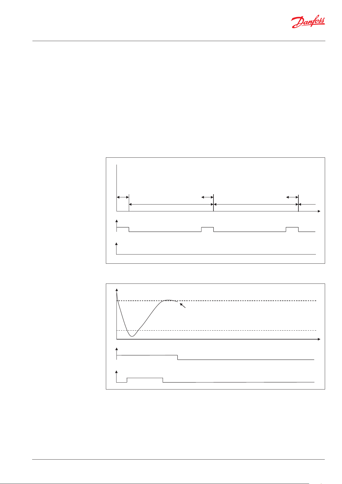
Working cycle The Danfoss IPS 8 operates in 24-hour cycles, of
which 45 minutes are dedicated to an R452A pull
down. At power on, the pull down is initiated
immediately. If no NC gases are detected during
the 45 minute pull down, the system will close
the solenoid valve at purge point 1 and open the
solenoid valve at point 2. After a cycle time of 24
hours/N (Number of purge points), the
compressor will pull down again condensing the
ammonia. After 24 hours, all purge points have
been vented one time.
To identify NC gases, the controller utilizes upper
and lower thresholds for R452A evaporating
temperature. If, during pull down, the
temperature continues decreasing and the lower
threshold is passed, the controller considers
Power on
Purger Pull down
(PDT): 45 min
Cycle (CST) *
this to be a high concentration of NC gases
and opens the purge solenoid valve. The purge
valve will stay open until sufficient condensing
ammonia is present to lift the R452A evaporating
temperature above the upper threshold.
The compressor will continue running and if the
temperature again decreases below the lower
threshold, a new purge will be performed. This
process will be repeated until the R452A heat
exchanger temperature stays above the lower
threshold for >45 minutes following the previous
closure of the purge valve.
Purger Pull down
(PDT): 45 min
Cycle (CST) *
Purger Pull down
(PDT): 45 min
Compressor
On
Off
Purge valve
Fig. 2 - Power on & Cycle at no NC gases present: CST (compressor start time) and PDT (pull down time) are configurable
* Cycle (CST) = 24 hours/N (number of purge points)
Upper Threshold (VClseT)
Non condensables has been purged
- new cycle starts *
Evaporator Temp. (Tsat452)
Compressor
On
Off
Purge valve
Lower Threshold (VClseT)
Fig. 3 - Purging procedure - Low R452A evap. temperature detected during PDT: Thresholds are configurable
* If low evaporator temperature is detected (passing lower threshold), the purging procedure will be repeated immediately
© Danfoss | DCS (ms) | 2021.04
BC344024774466en-000401 | 7
Page 8
User Guide | Intelligent Purging System (IPS 8) Ammonia
Air traps
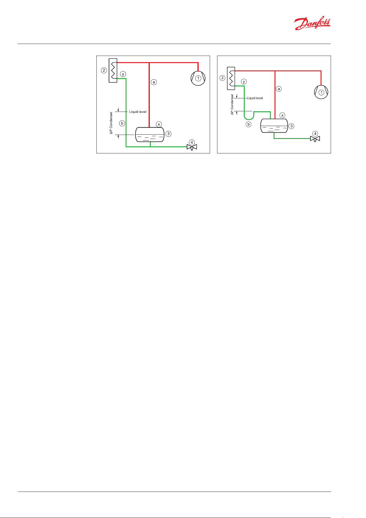
Fig. 4 Liquid level. Bottom connected receiver Fig. 5 Liquid level. Top connected receiver
For systems with low pressure liquid level control,
the correct condenser/ receiver installation is as
shown in Fig. 4 and Fig. 5.
The discharge gas from the compressor (1) is
led to the condenser (2) where it is condensed.
The receiver (3) holds the liquid until there is a
demand for liquid from the LP side, e.g., until the
expansion valve (4) opens. If the expansion valve
is closed, the liquid condensed in the condenser
will need to be stored in the receiver and the
level will increase. To ensure a free flow to the
receiver, the gas must be allowed to leave the
receiver; this process is accomplished through
the pressure equalizing line (a). The pressure
equalizing line makes the pressure in the receiver
the same as in the compressor discharge line.
The pressure in the condenser outlet is lower due
to the pressure loss in the condenser. Since the
condenser outlet pressure is lower than in the
receiver, it is therefore necessary to mount the
condenser higher than the receiver and allow for
a higher liquid level in the piping between the
condenser and the receiver (b).
The liquid column in the line (b) compensates for
the pressure difference between the condenser
outlet and the receiver.
Fig. 4 shows the liquid connection at the bottom
of the receiver.
If the liquid from the condenser is connected to
the top of the receiver (Fig. 5), a slightly different
arrangement must be made.
The liquid line (b) from the condenser to the
receiver will need to have a goose neck/liquid
trap to ensure that the liquid column is actually
established.
As air is heavier than ammonia gas, the air will
collect in two locations in this type of installation:
On top of the liquid in the receiver (x) and/or
on top of the liquid in the drop leg from the
condenser (y).
8 | BC344024774466en-000401
© Danfoss | DCS (ms) | 2021.04
Page 9

User Guide | Intelligent Purging System (IPS 8) Ammonia
Connection locations
Air purger installation in a low-pressure liquid level controlled installation
The correct locations for the air purger to be
connected to the ammonia plant are:
(See Fig. 6 and Fig. 7)
the condenser will be short-circuited.
The air purger must have its own liquid return
drop leg (c) connected in parallel with the
condenser’s drop legs (b).
- on top of the receiver or
- on top of the liquid in the drop leg from the
condenser.
When the purger is connected to the receiver
i.e. solenoid (px) open, the liquid level in the air
purgers drop leg (c) will be equal to the receiver
The air purger (5) is connected to the two purge
points through solenoid valves (px and py).
Note that only one solenoid should be open at
any given time, otherwise the liquid column in
liquid level (3); when the purger is connected to
the condenser outlet i.e. solenoid (py) open, the
liquid level will
be equal to the liquid level in the
condenser drop leg (b).
Fig. 6 Purger connections (px) & (py). Drain piping (c) must be vertical/downward slope
Alternatively, the air purger draining of liquid can
be achieved effectively through an HP float valve
(6) to the low pressure side (see Fig. 7).
© Danfoss | DCS (ms) | 2021.04
Fig. 7 Purger connections (px) & (py). Drain piping (c) must be vertical/downward slope
BC344024774466en-000401 | 9
Page 10
User Guide | Intelligent Purging System (IPS 8) Ammonia
Connection locations
(continued)
General
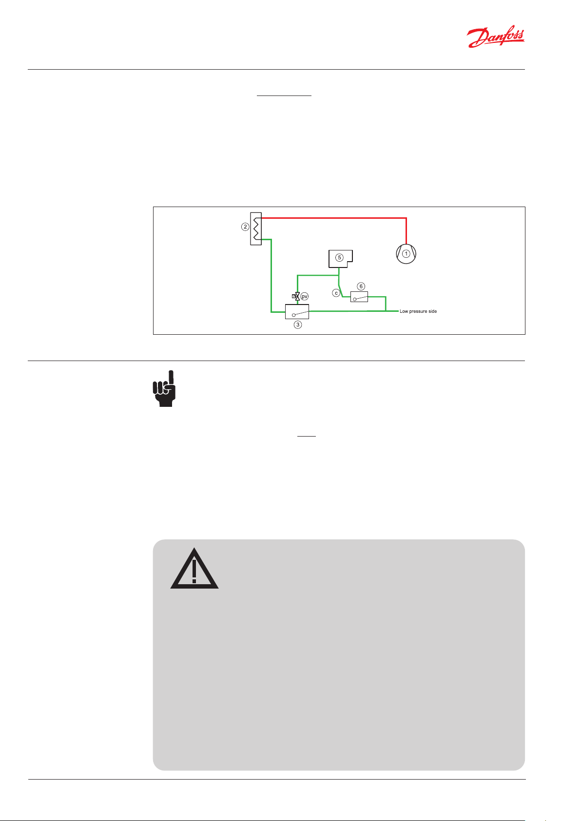
Air purger installation in a high-pressure liquid level controlled installation
For systems with a high-pressure liquid level
control, the air will collect in the float valve (3).
(See Fig. 8).
The compressor (1) supplies high-pressure gas to
the condenser (2), where it is condensed.
The float valve (3) will flash any liquid back to
the LP side. The air purger (5) must be connected
to the float valve through a solenoid valve (pv).
Fig. 8 Purger connections (pv). Drain Piping (c) must be vertical/downward slope
The air purger must always be mounted
above the highest liquid level to be able
to drain the ammonia condensed in it.
Otherwise, the air purger can flood and
potentially purge ammonia liquid.
The ammonia liquid condensed in the air purger
must be drained through drain pipe (c) to the LP
side via a float valve (6).
The purger liquid return leg (c) must
always be mounted vertically or at
minimum, with a downward slope.
The solenoid valves at the connection
points must never be activated at the
same time. Finalize purging at one
location before switching to the next.
Cod. 99000572
WARNING !
Follow the installation guide strictly during Purger installation.
Install the Purger unit in a location where the bottom flange level
and any gas inlet connection level is above any possible ammonia
liquid level.
Liquid drain piping from the purger must always have a downward
slope.
Install a shut off valve close to the bottom flange entrance to
enable removal of the unit and closing for high pressure ammonia
gas.
Connect proper resistant piping to the purging outlet pipe and
ensure the purged non-condensables are discharged into a water
bath of max. 200 liter.
10 | BC344024774466en-000401
© Danfoss | DCS (ms) | 2021.04
Page 11
User Guide | Intelligent Purging System (IPS 8) Ammonia
Connection points
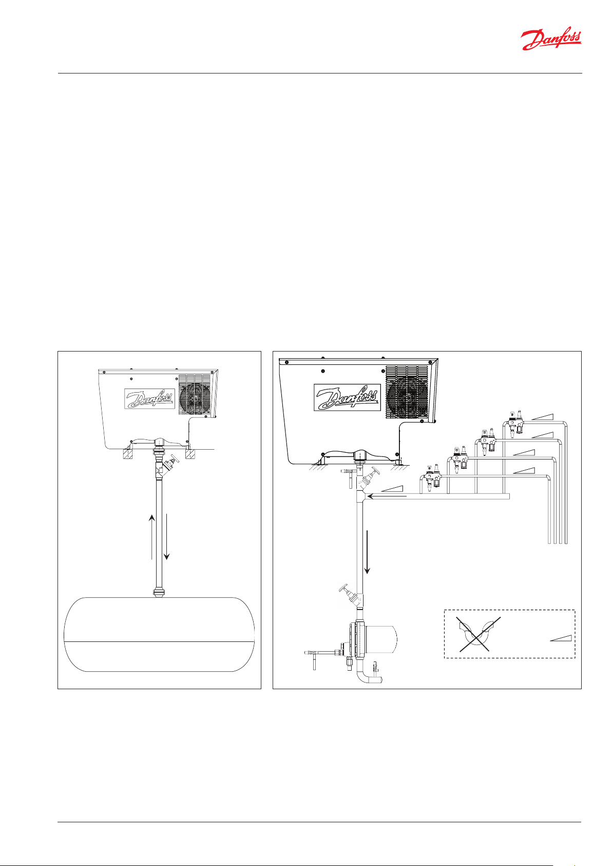
Multi-point purging
Single point purging setup is possible (Fig. 09) i.e.
no solenoid valves with the Danfoss IPS 8 unit.
This kind of installation should be installed as
shown in Fig. 9 i.e. above the receiver or using a
float valve. (See section on connection locations).
For single point purging as in Fig. 09, the setting
in the MCX for the number of valves to ‘0’ or
switch off the multi-purging functionality in the
general setup (y02).
As factory default, the Danfoss IPS 8 is configured
to handle 8 purge points. The correct amount of
purge points connected needs to be setup in the
MCX controller after power-up. Both power and
control wiring of the installed solenoid valves
coils should take place prior to first power up.
NEVER HAVE MORE THAN 1 PURGE POINT
OPEN AT A TIME.
Always close one purge valve before opening
the next.
This is done by turning the purger unit power
on (label y02) and entering the number of
actual purge points in the program. See section
“Programming/configuration”.
SVA
Ammonia Liquid
Ammonia gas + NC gases
Receiver
Liquid drain to Low
pressure side
Fig. 9 Single point purging from receiver Fig. 10 Multi-point purging from up to 8 purging points
SNV
SNV
SVA
NH₃ gas + NC gases
NH₃ bypass for
draining purger
Ammonia Liquid
SVA
SV3
SNV
ICF 15-4
Purge Points
- up to 8 points
Be aware of liquid traps
Where slope is
shown above, ensure
downward sloping
pipe flowing towards
purger drop leg.
© Danfoss | DCS (ms) | 2021.04
BC344024774466en-000401 | 11
Page 12
User Guide | Intelligent Purging System (IPS 8) Ammonia
* F
and ser
installed between 0,05 to 1,1 m (2 to 43 in)
above ser
Installation The Danfoss IPS 8 must be installed in
accordance with locations recommended in the
Connection locations and Connection points
sections of this document.
The unit has a protection rating of IP55 and may
be installed outside, in ambient temperature
ranges from from -10 °C to 43 °C / 14 °F to 109 °F).
Avoid installation in direct sunlight as this may
lead to excessive sunlight exposure and ambient
temperatures above allowed limits. For ambient
temperatures below -10 °C (14 °F) the air purger
must be installed in a heated and ventilated
area. The unit must be installed in a non-ATEX
atmosphere as the purger unit is not explosion proof.
The purger unit should be kept in an upright
position at all times - from receipt to final
installation.
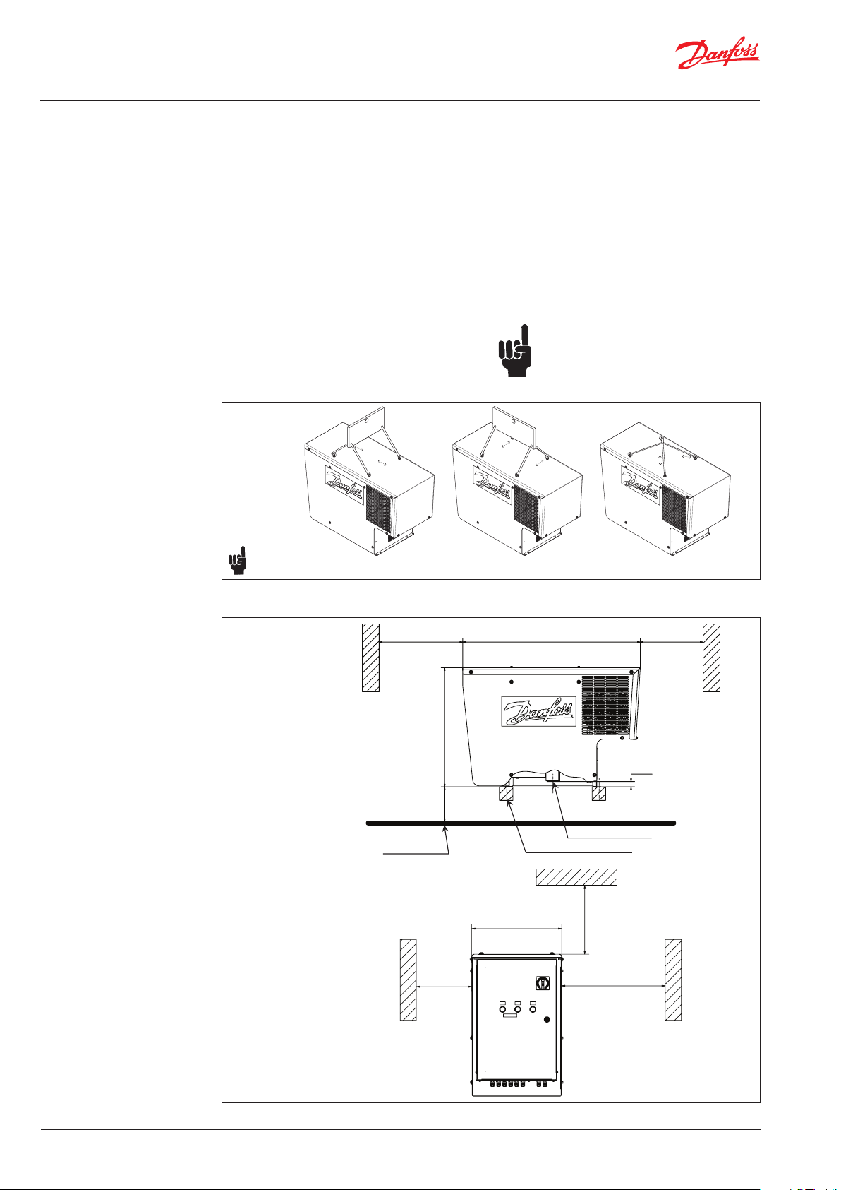
Lifting Procedure
.
All 4 lifting eyes must be positioned correctly, to match the actual used lifting gear
All 4 lifting eyes must be used
Fig. 11
Use all 4 lifting eyes and suitable lifting gear
during installation (unit weight = 100 kg/220 lbs).
Install the unit on an even horizontal base 0.05
to 1.1 meter (2 to 43 in) above a service platform
with sufficient support and allowing the purger
subframe to be bolted to the support (see
example in Fig. 12). Maintain recommended
distances in all directions (Fig. 12) to allow fan
cooling and servicing.
Always leave the unit off for at least 12 hours
from finished installation to first time power up.
It is important that the support
construction is level to ensure the
internal liquid trap is properly filled.
Angle to horizontal < 2 degrees
Min. 900 mm 1051 mm Min. 500 mm
or easy access to the main switch
* For easy access to the main switch
vicing, the Purger unit shall be
and servicing, the Purger unit shall be
installed between 0,05 to 1,1 m (2 to 43 in)
above service platform level.
vice platform level.
Service platform
703
32 mm
*
Flange for R717 access
Support for 100 kg/ 220 lbs
446 mm
Min. 300 mm
Min. 300 mm Min. 900 mm
12 | BC344024774466en-000401
Fig. 12 Installation dimensions
© Danfoss | DCS (ms) | 2021.04
Page 13
User Guide | Intelligent Purging System (IPS 8) Ammonia
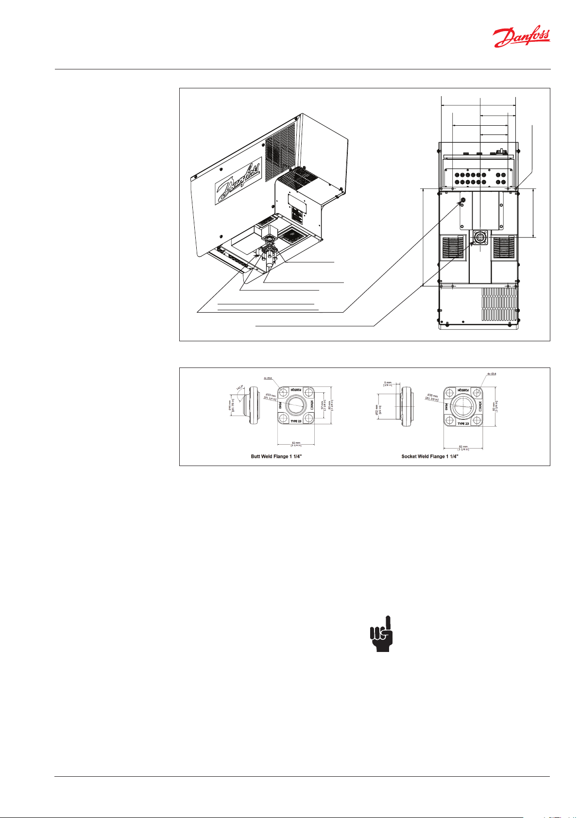
Installation (continued)
Purging pipe OD 17.2 for rubber hose to water bath
Do not unscrew restrictor inside pipe.
Risk of purging high NH₃ concentration
Fig. 13 Ammonia connection
Enclosed gasket
Enclosed bolts, Torque: 60 Nm
(44.3 ft lb) diagonal tension
Enclosed weld flange (fig. 14)
Flange for NH₃ connection. Remove rubber plug
547
416,4
198
310
155
8 x 11 mm (hole)
274
Fig. 14 Enclosed weld flange
1. Prepare the ammonia pipework with the weld
flange according to Fig. 13 and Fig. 14. The
main/drain piping should never be smaller
than inner diameter Ø37 mm (1.5 in).
2. Complete the supporting structure able to
carry 100 kg (221 lbs).
3. Lift the purger into position using the lifting
eyes on each side of the purger’s cabinet.
Remove the rubber plug from the flange
opening.
4. Connect the weld flange with the purger flange
using the enclosed flat gasket and tighten the
supplied 4 bolts diagonally to a torque of 60 Nm
(44.3 ft-lb).
5. Insert 4 bolts (not supplied) through the purger
frame and the support construction and tighten.
6. Perform a leak test to ensure an airtight
connection.
7. In the event the purger unit needs to be
dismantled please contact Danfoss for
instructions.
8. Correctly install a suitable pipe/hose from the
purge solenoid valve for blow-off of NC gases
in accordance with local or national
regulations.
9. Prepare an outside water tank with a maximum
of 200 liters (53 gal.) and ensure the piping
allows the purged gas to be immersed in the
water.
10. Regularly check the pH level of the tank’s
contents.
11. The pH level should never exceed 12.6.
Otherwise the water content must be renewed.
12. Dispose of concentrated waste water in
accordance
with to local/national regulations.
Note: Prior to replacing the water in the
water tank ensure that the purger is
switched off and the shut off valve at the
flanged purger inlet is closed. Leave the
unit in this condition for a period to allow
the remaining gas in the piping to be
dissolved/released.
Watch out for bubbles.
Establish a procedure for regular
checking the pH level and bubble
If continuous bubbles are observed
water tank during ‘‘stand by” (Green light
indicator) in normal operation, one or
more of the purge solenoid valves needs
repair or replacement.
pattern.
in the
© Danfoss | DCS (ms) | 2021.04
BC344024774466en-000401 | 13
Page 14

User Guide | Intelligent Purging System (IPS 8) Ammonia
Electrical wiring
The internal wiring of the purger is done at the
factory. Only the electrical wiring for the main
power supply, the purge point solenoids and
optional bus communication needs wiring on site.
It is highly recommended that all external cables
coming from the IPS 8 to the power supply and
to all purge point solenoids are protected by
metallic pipes.
WARNING
Electrical
hazards.
Authorized
personnel only.
STANDBY
RUN ERROR
PURGING
Fig. 15 Controller box external
Controller box cover can only be opened at key unlock and with the main switch off.
Note: Authorized personel only
ON/OFF Switch
Key Lock
Compressor/condenser
fan On/Off
Purge valve
ANALOG OUTPUT 5-6
AO5
DIGITAL INPUT 2
COM
DI 2
DI 2H
AO6
COM
DIGITAL INPUT 1DIGITAL OUTPUT 14
DIGITAL INPUT 3
COM
DI 3H
Compressor relay24V Converter
Main Power
230V 60 Hz
L
N
Earth
Main Switch
Solenoid valves
On/Off
MCX15B Controller
On/Off
AI3
AI1
AI2
DI 1
D1 H
COM
COM
NO 15
NO 14
NC 14
NC 15
DIGITAL OUTPUT 15
DIGITAL INPUT 4
DI 3
DI 4
COM
COM
DI 4H
DIGITAL INPUT 9-12
DIGITAL INPUT 5-8
DI 5
DI 9
DI 7
DI 6
DI 8
COM
DI 10
COM
5V+
ANALOG INPIT 1-6
DIGITAL INPUT 13-16
COM
DI 11
DI 12
COM
DI 13
DI 15
DI 14
DI 16
AI7
AI8
AI9
AI10
AI6
AI4
AI5
COM
5V+
COM
5V+
12V+
ANALOG INPUT 7-10
MCX
CAN RJ
DIGITAL INPUT 17-18
COM
COM
DI 17
DI 18
CAN
L
N
POWER
MCX15B Controller
14 | BC344024774466en-000401
Fig. 16 Controller box internal
Optional 24V DC
power supply for (8)
purge solenoids
(not included)
Output terminals for:
Up to 8 purge points
ICFD drain valve
© Danfoss | DCS (ms) | 2021.04
Page 15

User Guide | Intelligent Purging System (IPS 8) Ammonia
Electrical wiring
(continued)
230V AC
QS1
L
N
QM1 QM2
L/1
N/1
L/4
QM3
L/5
KL1 KL1
L/3
Crankcase
heater
GD1 GD2
24V DC
0V DC
Power supply
MCX15B
9
8
Power supply
Solenoid valves*
L/2
Press.
Switch
M1 M2 VR1
1 1 1
Compressor
Condenser
Fan
Extraction
air fan
TR
RC
*When using GD2 24V DC, remove 1-2 and 3-4 bridges between the terminals and connect power supply
Fig. 17 Power Supply
MCX15B OUTPUT
C 1
NO 1
N1
L 1
NO 2
C 3
C 2
NO 3
NO 4
5
C 4
C
C 6
NO 5
NO 6
C 7
NO 7
NO 8
C 9
C 8
NO 9
C 10
NO 10
NC 10
11
NO
C 12
NC 12
NO 12
C 13
NO 13
NC 13
C 14
NC 14
NO 14
C 15
NC 15
NO 15
C 11
NC 11
24V DC
12
345
Solenoid valve
0V DC
Fig. 18 Controller MCX15B Inputs and Outputs
8
6
7
10
11
12
13
Solenoid valve
Solenoid valve
Solenoid valve
Solenoid valve
System running
System running
System error
14
15
Solenoid valve
16
Solenoid valve
Solenoid valve
17
Solenoid valve
18
Solenoid valve
9
© Danfoss | DCS (ms) | 2021.04
BC344024774466en-000401 | 15
Page 16

User Guide | Intelligent Purging System (IPS 8) Ammonia
Electrical wiring
(continued)
24V DC 24V DC
0V DC 0V DC
6
AO
AO 5
COM
DI COM
DI 2DI 2HDI 3DI 3H
DI COM
Fig. 19 Controller MCX15B Inputs
Light Indicators
DI COM
KL1
Compressor
relay
26
DI 1
DI 4
DI 4H
Discharge
Temp. sensor
Suction
Temp. sensor
Temp.
sensor
Low
pressure
transmitter
High
pressure
transmitter
R717
XT1
ST1
212223
19
20
AI 1AI 2
L1
N 1
DI 1H
AO 1
AO 4
AO 2
AO 3
COM
AI 3
5V+
12V+
5V+
ST2
ST3
COM
BPL
AI 7
24
25
4
AI
AI 5
AI 6
COM
BPH
AI 8
AI 9
AI 10
5V+
MCX15B INPUT
DI COM
DI 5DI
6
DI 7
DI 9
COM
DI 8
DI 12
DI 10
COM
DI 11
DI 13
DI 14
DI 15
DI 16
COM
COM
DI 17
DI 18
COM
GND
D +
D +
GND
D -
D -
ON/OFF Switch
R120
CAN GND
CAN H
CAN L
CAN HIDCAN L
CAN GND
STANDBY RUN ERROR
Green
Yellow
light
PURGING
Red
light
light
Key Lock
Fig. 20
Lights ON Status
Compressor ONCompressor
OFF
Purge Valve ONPurge Valve
OFF
Green Stand by x x
Yellow Run x x
Green & Yellow Purging x x
Green & Yellow
& Red
Red
* The purger continuous purging until max running period (default 160 h) is reached and the purger compressor will stop
** The purger compressor stops when alarm occurs
Uninterupted Long time
purging (> 150 h)
Occurs when: Check list
of alarms description
x x*
(x**) x** x
Alarm
16 | BC344024774466en-000401
© Danfoss | DCS (ms) | 2021.04
Page 17

User Guide | Intelligent Purging System (IPS 8) Ammonia
Upper Threshold for Purge Valv
Log of purging events
Quick Startup
Navigation - built in MCX
controller
(Placed at the rear of the front
panel door)
R717 low Pres limit
Actual R717 Pres
Actual R452A Pres
Lower Threshold for Purge Valve
Actual R452A Temp
e
For the fastest possible system configuration after connecting all purge points to the IPS and following
first power up of the IPS, follow these simple instructions:
1. Navigate from the Main Menu to Login
2. Enter password '200'.
3. Choose 'Parameters'.
4. Choose 'Unit Config'
5. Choose 'Valve Settings'
6. Enter the amount of purge solenoid valves connected to the IPS.
After switching on the controller, a display
window will momentarily show the actual
software version, followed by the default main
While in operation mode, the Up/Down arrow
buttons lead the user to the status windows
described in Table 01 below.
operating window shown in Fig. 26.
Up
Down Enter
Compressor on Error/Alarm Purge valve open Purge point (1-8)
Esc
.
Not
Used
Main screen, current informaon on IPS status
Status of purging process and purging counters
Temperature and superheat status
Informaon on Purge points acvity
Fig. 21 - Default main window. Operating (start) mode. (Examples only)
Table 01 - Status windows
Purge Point percentage Distribution of the actual purging on the various purge points
Dis. temp. Actual R452A discharge temperature (°C)
Main Window default See above
Cycle info Acc. time Purge valve open (h)
Past events Last 7 purging events (min)
© Danfoss | DCS (ms) | 2021.04
BC344024774466en-000401 | 17
Page 18

User Guide | Intelligent Purging System (IPS 8) Ammonia
Configuring using the LCD
By pressing the main menu will show up with the options below
Table 02
Main menu navigation
Main Menu Submenu Submenu/status Submenu/status Min Max Default Description Label
Active alarms
Alarms
Login Password *** 200 N/A
Start
Parameters
Input/Output Input / Output Display & Config
Reset alarms Reset all actual alarms
Log history View log history
Clear log
history
Turn On Main swith ON
Turn Off Main swith OFF
Unit config
No alarm
up to 15 alarms
(see table
below)
Compressor
Limits settings
Up to 15 possible alarms listed by arrow up/down
Clear log history
0 sec 100 sec 20 sec SDT (Compressor start delay) CM2
5 min
180 min
24 hours
0 bar 5 bar 0.5 bar Comp Diff (Hysteresis min allowed ammonia pressure) CM5
0 bar 12 bar 6.5 bar Setpoint to start compressor CM1
2000
45 min PDT (Pull down time) CM3
min
2000
hours
min
768
1440
CST (Cycle time) CM4
min
160
PLT (Endless purging max time) VA5
hours
18 | BC344024774466en-000401
© Danfoss | DCS (ms) | 2021.04
Page 19

User Guide | Intelligent Purging System (IPS 8) Ammonia
Table 03
Occurring active alarms, possible reasons and recommended action
Label Parameter Name Description Possible Reason Recommended action
ALARMS
A01 General alarm Input from AI3 Leads to shut down of IPS 8 Fault in system connected to the DIO4 Input from AI3 Leads to shut down of IPS 9
E01 Temp Sensor Fault
E01 Temp Sensor Fault
E01 Temp Sensor Fault
E02 BPL Sensor Fault
E02 BPL Sensor Fault
E02 BPL Sensor Fault
E03 BPL Sensor Fault
E03 BPL Sensor Fault
E03 BPL Sensor Fault
E04 Low temperature
E05 High temperature
E05 High temperature Low R452a charge because of possible leak Locate and repair leak Evacuate Move the IPS to a lower ambient temperature
E06 Low pressure BPL Indicates too low R452a pressure Choked restrictor / wrong connection
E07 High pressure BPL Indicates too high R452a pressure R452s system pressure too high
E08 Low pressure BPH Indicates too low R717 pressure Closed stop valve
E09 High pressure BPH Indicates too high R717 pressure R717 system pressure too high Pressure is 24 bar
E10 System is OFF Indicates status of the main switch Main switch is OFF Switch ON the main switch
E11 Memory is full A memor y reset is required Memory is full from long time operation
E12 Totla purge time error
E13 Compressor ERROR
E14 Liquid alarm
E15 Memory wrong!
E16 Discharge sensor error Indicates no signal from temperature sensor
E17 Suction sensor error Indicates no signal from temperature sensor
All alarms except (*) activates red light on box outside
For alarms not resettable and/or cause not identified, please contact Danfoss
Level legend: 0 = Read view, 2 = Installer view (code 200) 3 = Danfoss Service view (Contact Danfoss)
Indicates no signal from temperature sensor
(R452a)
Indicates no signal from temperature sensor
(R452a)
Indicates no signal from temperature sensor
(R452a)
Indicates no signal from pressure transmitter
(R452a)
Indicates no signal from pressure transmitter
(R452a)
Indicates no signal from pressure transmitter
(R452a)
Indicates no signal from pressure transmitter
(R717)
Indicates no signal from pressure transmitter
(R717)
Indicates no signal from pressure transmitter
(R717)
Indicates too low ambient temperature
(<-10 °C)
Indicates too high ambient temperature
(>120 °C)
This occurs when PLT is activated System will
automatically restart when CST has expired
Indicates no status is being received from
relay KL01
Signal from the LLS that there is liquid in the
evaporator
Wrong counter values The unit will
automatically repair itself
Broken wire to R452a temperature sensor
Electrical supply failure supplying R452a
temperature sensor
Temperature measurement of the R452a line
is out of range
Broken wire to R452A pressure transmitter
Electrical supply failure to the R422a pressure
transmitter
Pressure measurement of the R452a line is out
of range
Broken wire to R717 pressure transmitter
Electrical supply failure to the R717 pressure
transmitter
Pressure measurement of the R717 line is out
of range
Too low ambient temperature Move the IPS to a higher ambient temperature
Too high ambient temperature Move the IPS to a lower ambient temperature
Restrictor is blocked Replace the restrictor
Possible broken wire from the MCX Repair broken wire from the MCX
Repair temperature sensor wire or replace
temperature sensor
Repair or replace power source
Compare temperature with another
temperature sensor reading and replace
temperature sensor if needed
Repair pressure transmitter wire or replace
pressure transmitter
Repair or replace power source
Compare pressure with another pressure
reading and replace pressure transmitter if
needed
Repair pressure transmitter wire or replace
pressure transmitter
Repair or replace power source
Compare pressure with another pressure
reading and replace pressure transmitter if
needed
Factory setting 0.3 bar, we can have several
problems: a) Restrictor is blocked (clean it).
b) Wrong piping and as addition ammonia is
draining, so check piping’s. c) Check SV float
a) Expansion valve is not working
b) To high ambient temperature (24 bar /54 ºC)
Purge points are blocked, or flange is blocked
with rubber plug
Clean MCX memory by means of finding
Parameters_UnitConfig_
© Danfoss | DCS (ms) | 2021.04
BC344024774466en-000401 | 19
Page 20

User Guide | Intelligent Purging System (IPS 8) Ammonia
Modbus RTU
Good Practice
The wiring of Modbus RTU (RS485) must be carried out in accordance with the standard ANSI/TIA/EIA-485-A-1998.
Galvanic separation shall be provided for segments crossing buildings.
Common ground shall be used for all devices on the same network inclusive router, gateways etc.
All bus connections in the cables are made with twisted pair wires.
The recommended cable type for this is AWG 22/0.32 mm². If used for longer distances please use a AWG 20/0.5mm² or AWG 18/0.75mm²
cable. The cables characteristic impedance shall be between 100 – 130Ω The capacitance between conductors shall be less than 100 pf
per meter.
Note: the length of the cables influence the communication speed used. Longer cable lengths mean lower baud rate should be used.
Maximum cable length allowed is 1200m.
Use a minimum 20 cm distance between 110V/230V/400V power line cables and bus cables.
Table 04
Modbus RTU Registers
Register Parameter Name Description
GENERAL > SETUP
3001 ON/OFF
3002 Activate Multipurger
3003
3007
3008
3009
3010 Password level 1
3011 Password level 2
3014 PDT
3015 CST
3016 PLT
Restore default
parameters
GENERAL > SERIAL
SETTINGS
Serial address (Modbus
and CAN)
Serial baudrate
(Modbus)
Serial settings
(Modbus)
GENERAL >
PASSWORD
UNIT CONFIG >
COMPRESSOR
0: Main switch off
1: Main switch on
Switch on/off
multipurging
functionality
0: No
1: Yes, switch on
multipurging
functionality
0: No
1: Yes, restore default
parameters
2 1 100 1 N/A RW 3/6 Short Yes
TThe rate at which
information is
transferred in the
RS485 communication
channel
0: 0
1: 12
2: 24
3: 48
4: 96
5: 144
6: 192
7: 288
8: 384
0: 8N1
1: 8E1
2: 8N2
password for user
level 1
password for user
level 2
Pull down time of
compressor
Delay between purge
cycles (single purge)
Alarm for endless
purging
User
Level
Min Value Max Value
2 0 1 1 Enum 1 RW 3/6 Short Yes
2 0 1 1 Enum 2 RW 3/6 Short Yes
2 0 1 0 Enum 2 RW 3/6 Short Yes
2 0 8 6 Enum 3 RW 3/6 Short Yes
2 0 2 1 Enum 4 RW 3/6 Short Yes
3 0 999 100 N/A RW 3/6 Short Yes
3 0 999 200 N/A RW 3/6 Short Yes
2 5 CM4 45 min RW 3/6 Short Yes
2 180 2000 1440 min RW 3/6 Short Yes
2 24 768 24 h RW 3/6 Short Yes
Default
Value
Unit/
Type
Read/
Write
Modbus
Function
Code
Modbus
Data Type
Persistent
Yes/No
20 | BC344024774466en-000401
© Danfoss | DCS (ms) | 2021.04
Page 21

User Guide | Intelligent Purging System (IPS 8) Ammonia
Register Parameter Name Description
3022 Max_PP
3034 Setpoint
3035 Tsh Setpoint for superheat 2 5,0 40,0 15 °C R/W 3/6 Short Yes
1859 Reset Alarms Reset alarm 0 0 2 0 N/A R/W 3/6 Short Yes
8101 SystemOnOff
8102 ValveStatus
8103 CompressorStatus
8104 ALARActive
8105 PressTotemp
8106 ValveCount
8108 ComprTime
8110 COmprStartAfter
9901
8112 ValveHour
8114 StatusKL
8115 WaringCompr
8116 ValveSetpoint
8117 ValveClose
8119 Event1
8121 Event2
UNIT CONFIG >
VALVE SETTINGS
UNIT CONFIG >
LIMITS SETTINGS
STATUS VAR > MCX
DESIGN HOTSPOTS
Advanced Setting ResetMem
Used amount of purge
points - part of initial
setup
Pressure threshhold
for compressor
Feedback from the
main switch
Feedback from the
purge valve - open/
closed
Feedback from the
compressor - on/off
Any alarm active
indicator
Suction temperature
(calculated from
pressure on suction)
The amount of purge
valve activations
Remaining time for
compressor pull-down
for the actual purge
pointr cycle
The delay between
the purging cycles
Recommend default
setting only - All
logged values are
reset
0: NO
1: YES
The amount of hours
that the main purge
valve has been active
Status of KL01 relay
(compressor and
crankcase heater)
Indicates problem
with compressor
status
Temperature
threshhold for the
opening of the main
purge valve
Temperature
threshhold for the
closing of the main
purge valve
Purge cycle event counts the minutes
that the purge valve
has been open on a
finished cycle
Purge cycle event counts the accumative
minutes that the
purge valve has been
open on a finished
cycle
User
Level
Min Value Max Value
2 0 8 8 N/A RW 3/6 Short Yes
2 0,0 12,0 6.5 bar R/W 3/6 Short Yes
0 -32768 32767 0 Enum 1
0 -32768 32767 0 Enum 1
0 -32768 32767 0 Enum 1 R/W 3/6 Short Ye s
0 -32768 32767 0 Enum 2
0 -327,7 327,7 0 °C
0 -2147483648 2147483647 0 N/A
0 -2147483648 2147483647 0 Minutes
0 -2147483648 2147483647 0 Minutes
0 0 1 0 Enum 2 R/W 3/6 Short Ye s
0 -214748364,8 214748364,7 0 Hours
0 -32768 32767 0 Enum 2
0 -32768 32767 0 Enum 2
0 -2147483648 2147483647 0 °C
0 -2147483648 2147483647 0 °C
0 -3276,8 3276,7 0 Minutes
0 -3276,8 3276,7 0 Minutes
Default
Value
Unit/
Type
Read/
Write
Read
only
Read
only
Read
only
Read
only
Read
only
Read
only
Read
only
Read
only
Read
only
Read
only
Read
only
Read
only
Read
only
Read
only
Modbus
Function
Code
Modbus
Data Type
3 Short No
3 Short No
3 Short No
3 Short No
3 Long No
3 Long No
3 Long No
3 Long No
3 Short No
3 Short No
3 Short No
3 Long No
3 Long No
3 Long No
Persistent
Yes/No
© Danfoss | DCS (ms) | 2021.04
BC344024774466en-000401 | 21
Page 22

User Guide | Intelligent Purging System (IPS 8) Ammonia
Register Parameter Name Description
Purge cycle event counts the accumative
8123 Event3
8125 Event4
8127 Event5
8129 Event6
8131 Event7
8133 PP1
8135 PP2
8137 PP3
8139 PP4
8141 PP5
8143 PP6
8145 PP7
8147 PP8
8149 Val1
8150 Val2
8151 Val3
8152 Val4
8153 Val5
8154 Val6
8155 Val7
8156 Val8
8158 TempStatus
8159 BPLStatus The pressure on R452 0 -32768 32767 0 bar
8160 BPHStatus The pressure on R717 0 -2147483648 2147483647 0 bar
minutes that the
purge valve has been
open on a finished
cycle
Purge cycle event counts the accumative
minutes that the
purge valve has been
open on a finished
cycle
Purge cycle event counts the accumative
minutes that the
purge valve has been
open on a finished
cycle
Purge cycle event counts the accumative
minutes that the
purge valve has been
open on a finished
cycle
Purge cycle event counts the accumative
minutes that the
purge valve has been
open on a finished
cycle
The time percentage
for this purge point
The time percentage
for this purge point
The time percentage
for this purge point
The time percentage
for this purge point
The time percentage
for this purge point
The time percentage
for this purge point
The time percentage
for this purge point
The time percentage
for this purge point
This indicates if the
purge point is active
This indicates if the
purge point is active
This indicates if the
purge point is active
This indicates if the
purge point is active
This indicates if the
purge point is active
This indicates if the
purge point is active
This indicates if the
purge point is active
This indicates if the
purge point is active
The measured
temperature on the
discharge line of
compressor
User
Level
Min Value Max Value
0 -3276,8 3276,7 0 Minutes
0 -3276,8 3276,7 0 Minutes
0 -3276,8 3276,7 0 Minutes
0 -3276,8 3276,7 0 Minutes
0 -3276,8 3276,7 0 Minutes
0 -32768 32767 0 %
0 -32768 32767 0 %
0 -32768 32767 0 %
0 -32768 32767 0 %
0 -32768 32767 0 %
0 -32768 32767 0 %
0 -32768 32767 0 %
0 -32768 32767 0 %
0 -32768 32767 0 N/A
0 -32768 32767 0 N/A
0 -32768 32767 0 N/A
0 -32768 32767 0 N/A
0 -32768 32767 0 N/A
0 -32768 32767 0 N/A
0 -32768 32767 0 N/A
0 -32768 32767 0 N/A
0 -32768 32767 0 °C
Default
Value
Unit/
Type
Read/
Write
Read
only
Read
only
Read
only
Read
only
Read
only
Read
only
Read
only
Read
only
Read
only
Read
only
Read
only
Read
only
Read
only
Read
only
Read
only
Read
only
Read
only
Read
only
Read
only
Read
only
Read
only
Read
only
Read
only
Read
only
Modbus
Function
Code
Modbus
Data Type
3 Long No
3 Long No
3 Long No
3 Long No
3 Long No
3 Long No
3 Long No
3 Long No
3 Long No
3 Long No
3 Long No
3 Long No
3 Long No
3 Short No
3 Short No
3 Short No
3 Short No
3 Short No
3 Short No
3 Short No
3 Short No
3 Short No
3 Short No
3 Short No
Persistent
Yes/No
22 | BC344024774466en-000401
© Danfoss | DCS (ms) | 2021.04
Page 23

User Guide | Intelligent Purging System (IPS 8) Ammonia
Register Parameter Name Description
8161 DisTemp
8162 SuctionTemp
8163 TshValveStatus
8164 TshCalculate
ALARMS
1901 .08 General alarm
1901 .09 Temp Sensor Fault
1901 .10 BPL Sensor Fault
1901 .11 BPH Sensor Fault
1901 .12 Low temperature
1901 .13 Hi temperature
1901 .14 Low pressure BPL
1901 .15 Hi pressure BPL
1901 .00 Low pressure BPH
1901 .01 Hi pressure BPH
1901 .02 System is OFF
1901 .03 Memory is full
1901 .04 Totla purge time error
1901 .05 Compressor EROR
1901 .06 Liquid alarm
1901 .07 Memory wrong!
1902 .08 Discharge sensor error
1902 .09 Suction sensor error
The measured
temperature on the
purge valve
The measured
temperature on the
suction line
The measured value of
the superheat
The calculated value
of the superheat from
the refrigerant type
Input from AI3. Leads
to shut down of IPS 8
Indicates no signal
from temperature
R452A sensor
Indicates no signal
from pressure sensor
(R452a)
Indicates no signal
from pressure sensor
(R717)
Indicates too low
ambient temperature
(<-10 °C)
Indicates too high
ambient temperature
(>120 °C)
Indicates too low
R452a pressure
Indicates too high
R452a pressure
Indicates too low R717
pressure
Indicates too high
R717 pressure
Indicates status o the
main switch
A memory reset is
required
This occurs when PLT
is activated. System
will automatically
restart when CST has
expired
Indicates no status is
being received from
KL01
Signal from the LLS
that there is liquid in
the evaporator
Wrong counter
values. The unit will
automatically repair
itself
Indicates no signal
from temperature
sensor
Indicates no signal
from temperature
sensor
User
Level
Min Value Max Value
0 -32768 32767 0 °C
0 -2147483648 2147483647 0 °C
0 -32768 32767 0 °C
0 -2147483648 2147483647 0 K
0 0 1 0 AUTO R.
0 0 1 0 AUTO R.
0 0 1 0 AUTO R.
0 0 1 0 AUTO R.
0 0 1 0 AUTO R.
0 0 1 0 AUTO R.
0 0 1 0 AUTO R.
0 0 1 0 AUTO R.
0 0 1 0 AUTO R.
0 0 1 0 AUTO R.
0 0 1 0 AUTO R.
0 0 1 0 AUTO R.
0 0 1 0 AUTO R.
0 0 1 0 AUTO R.
0 0 1 0 AUTO R.
0 0 1 0 AUTO R.
0 0 1 0 AUTO R.
0 0 1 0 AUTO R.
Default
Value
Unit/
Type
Read/
Write
Read
only
Read
only
Read
only
Read
only
Read
only
Read
only
Read
only
Read
only
Read
only
Read
only
Read
only
Read
only
Read
only
Read
only
Read
only
Read
only
Read
only
Read
only
Read
only
Read
only
Read
only
Read
only
Modbus
Function
Code
Modbus
Data Type
3 Short No
3 Short No
3 Short No
3 Long No
3 Long No
3 Long No
3 Long No
3 Long No
3 Long No
3 Long No
3 Long No
3 Long No
3 Long No
3 Long No
3 Long No
3 Long No
3 Long No
3 Long No
3 Long No
3 Long No
3 Long No
3 Long No
Persistent
Yes/No
© Danfoss | DCS (ms) | 2021.04
BC344024774466en-000401 | 23
Page 24

User Guide | Intelligent Purging System (IPS 8) Ammonia
Register Parameter Name Description
I/O CONFIGURATION
ANALOG INPUTS
1005 BPL-1/34
1006 BPH-1/59
1007 Dis. Temp
1008 TempSuction
1009 NC Temp
DIGITAL INPUTS
1001.08 Status KL1
1001.09 On/Off
1001.10 General Alarm General Alarm input 2 0 1 0 N.O.
1001.11 LiquidAlarm Liquid Alarm input 2 0 1 0 N.O.
DIGITAL OUTPUTS 0 = OFF ; 1 = ON
1003.08 Compressor Compressor relay 2 0 1 N/A N.O.
1003.09 Valve Main purge valve relay 2 0 1 N/A N.O.
1003.10 Green Status LED 2 0 1 N/A N.O.
1003.11 Yellow Status LED 2 0 1 N/A N.O.
1003.12 DO_Red Status LED 2 0 1 N/A N.O.
1003.13 ICFD_Valve
1003.14 Valve1 Purge point valve relay 2 0 1 N/A N.O.
1003.15 Valve2 Purge point valve relay 2 0 1 N/A N.O.
1003.00 Valve3 Purge point valve relay 2 0 1 N/A N.O.
1003.01 Valve4 Purge point valve relay 2 0 1 N/A N.O.
1003.02 Valve5 Purge point valve relay 2 0 1 N/A N.O.
1003.03 Valve6 Purge point valve relay 2 0 1 N/A N.O.
1003.04 Valve7 Purge point valve relay 2 0 1 N/A N.O.
1003.05 Valve8 Purge point valve relay 2 0 1 N/A N.O.
1003.06 Alarm Alarm relay N/A 0 1 N/A N.C.
Pressure at the R452a
suction line
Condensing pressure
of R717
Measured discarge
temperature of
compressor
Measured suction
temperature
Measured non
Condensable gas
temperature
Compressor status
(KL01)
0: Compressor off
1: Compressor on
Main switch input
0: Main switch off
1: Main switch on
ICFD relay (solenoid
valve)
User
Level
Min Value Max Value
2 -1.0 34.0 N/A 0-5 V
2 -1.0 59.0 N/A 0-5 V
2 -50.0 170.0 N/A PT1000
2 -50.0 170.0 N/A PT1000
2 -50.0 170.0 N/A PT1000
2 0 1 1 N.O.
2 0 1 1 N.O.
2 0 1 N/A N.O.
Default
Value
Unit/
Type
Read/
Write
Read
only
Read
only
Read
only
Read
only
Read
only
Read
only
Read
only
Read
only
Read
only
Read
only
Read
only
Read
only
Read
only
Read
only
Read
only
Read
only
Read
only
Read
only
Read
only
Read
only
Read
only
Read
only
Read
only
Read
only
Modbus
Function
Code
N/A N/A N/A
Modbus
Data Type
3 Short No
3 Short No
3 Short No
3 Short No
3 Short No
3 Short No
3 Short No
3 Short No
3 Short No
3 Long No
3 Long No
3 Long No
3 Long No
3 Long No
3 Long No
3 Long No
3 Long No
3 Long No
3 Long No
3 Long No
3 Long No
3 Long No
3 Long No
Persistent
Yes/No
24 | BC344024774466en-000401
© Danfoss | DCS (ms) | 2021.04
Page 25

User Guide | Intelligent Purging System (IPS 8) Ammonia
Maintenance/Service/
Disposal
Table 05
Maintenance checklist - Perform once a year minimum
1 Use P&I dagram and check that all powered components are working properly
2 Check for alarms in the MCX controller
3 Fans, air filters and fins must be cleaned for dirt and dust
4 Expansion valve must be inspected and must be replaced if damaged
5 Ensure expansion valves sensor bulb has good contact with suction line
6 Replace water in water bubble bath. Check pH level frequently and replace when pH > 12.6
7 Check cover is mounted correctly and all bolts are tightened accordingly
8 Check and verify the amperage of the unit
9 Check for abnormal compressor noises in normal operating conditions (may indicate loose bolts, worn bearings or pistons)
Table 06
Procedure to isolate IPS for servicing
Multipoint Single point purging from receiver
Close all supply lines from the purge points of the ammonia
1
system.
Do not close any stop valve between IPS 8 and float valve
2 Restart the controller to force pump-down Wait 20 minutes
3 Wait 20 minutes
Stop the compressor by turning the compressor switch QM1 to
4
the off position
Close the SVA shut-off valve in the drain line (located under
5
the IPS 8)
Release the remaining system pressure to atmosphere
by opening the SNV drain valve. This can also be done by
6
attaching a permanent magnet on the AKVA 10 valve for forced
opening
Restart the controller to force pump-down
Stop the compressor by turning the compressor switch QM1 to
the off position
Close the SVA shut-off valve in the drain line (located under
the IPS 8)
Release the remaining system pressure to atmosphere
by opening the SNV drain valve. This can also be done by
attaching a permanent magnet on the AKVA 10 valve for forced
opening
Disposal of the IPS 8
If an IPS 8 unit is worn out and has to be replaced,
the disposal must be done in accordance with
national legislation and only done by competent
personnel.
© Danfoss | DCS (ms) | 2021.04
BC344024774466en-000401 | 25
Page 26
26 | BC344024774466en-000401
© Danfoss | DCS (ms) | 2021.04
 Loading...