

Page 1
Application Guidelines
Danfoss Inverter scroll
compressor, VRJ
For Residential Applications - R410A
http://danfoss.us.com/
Page 2

Page 3

Application Guidelines
Content
Introduction ................................................... 4
Scroll compressor components ....................................4
Compressor size ..................................................................4
Performance .........................................................................4
Compressor model designation ................... 5
Nomenclature ......................................................................5
Label........................................................................................5
Serial number ...................................................................... 5
Technical specications ................................ 6
Compressor specications ..............................................6
Performance data ..............................................................6
Variable speed drive specications .............................6
Bearings lubrication .......................................................... 6
Dimensions .................................................... 7
VRJ 028 - 035 - 044 ............................................................. 7
Mounting grommet ..........................................................7
Electrical data, connections and wiring ....... 8
Supply Voltage ................................................................... 8
Compressor electrical specications ........................... 8
LRA (Locked Rotor Amp)..................................................8
MCC (Maximum Continuous Current) ........................8
Winding resistance ............................................................8
Wiring connections .......................................................... 9
Terminal cover mounting ................................................ 9
Terminal cover removal ....................................................9
IP rating ..................................................................................9
Internal motor protection ............................................... 9
Phase sequence and reverse rotation protection ..9
Approvals and certicates ........................... 10
Approval and certicates ...............................................10
Pressure equipment directive 97/23/EC ..................10
Low voltage directive 73/23/EC, 93/68/EC...............10
Internal free volume .........................................................10
Operating conditions ................................... 11
Refrigerant and lubricants .............................................11
Motor supply.......................................................................11
Compressor ambient temperature .............................11
Application envelope ......................................................12
High and low pressure protection ..............................13
Crankcase heating ............................................................13
Oil return management ..................................................13
On/o cycling (cycle rate limit) ....................................14
Start-up sequence .............................................................14
System design recommendations .............. 15
General ..................................................................................15
Essential piping design considerations .....................15
Refrigerant charge limit .................................................16
Reversible heat pump systems ....................................16
Minimum sump superheat ............................................16
Preventing liquid ood back ........................................16
Water utilising systems ..................................................17
Loss of charge protection...............................................17
Oil level checking and top-up ......................................17
Sound and vibration management ............. 18
Starting sound level .........................................................18
Running sound level ........................................................18
Stopping sound level .......................................................18
Sound generation in a refrigeration system and air
conditioning system ........................................................18
Installation .................................................... 20
System cleanliness ............................................................20
Compressor handling and storage .............................20
Compressor mounting ....................................................20
Compressor holding charge ..........................................20
Tube brazing procedure .................................................20
Brazing material .................................................................20
Compressor connection .................................................21
Vacuum evacuation and moisture removal .............21
Liquid line lter driers ......................................................22
Refrigerant charging ........................................................22
Insulation resistance and dielectric strength ..........22
Compressor replacement after motor burn out ....22
Ordering information and packaging ........ 23
Packaging ............................................................................23
Ordering code numbers .................................................23
3AB141686422149en-US0301
Page 4
Application Guidelines
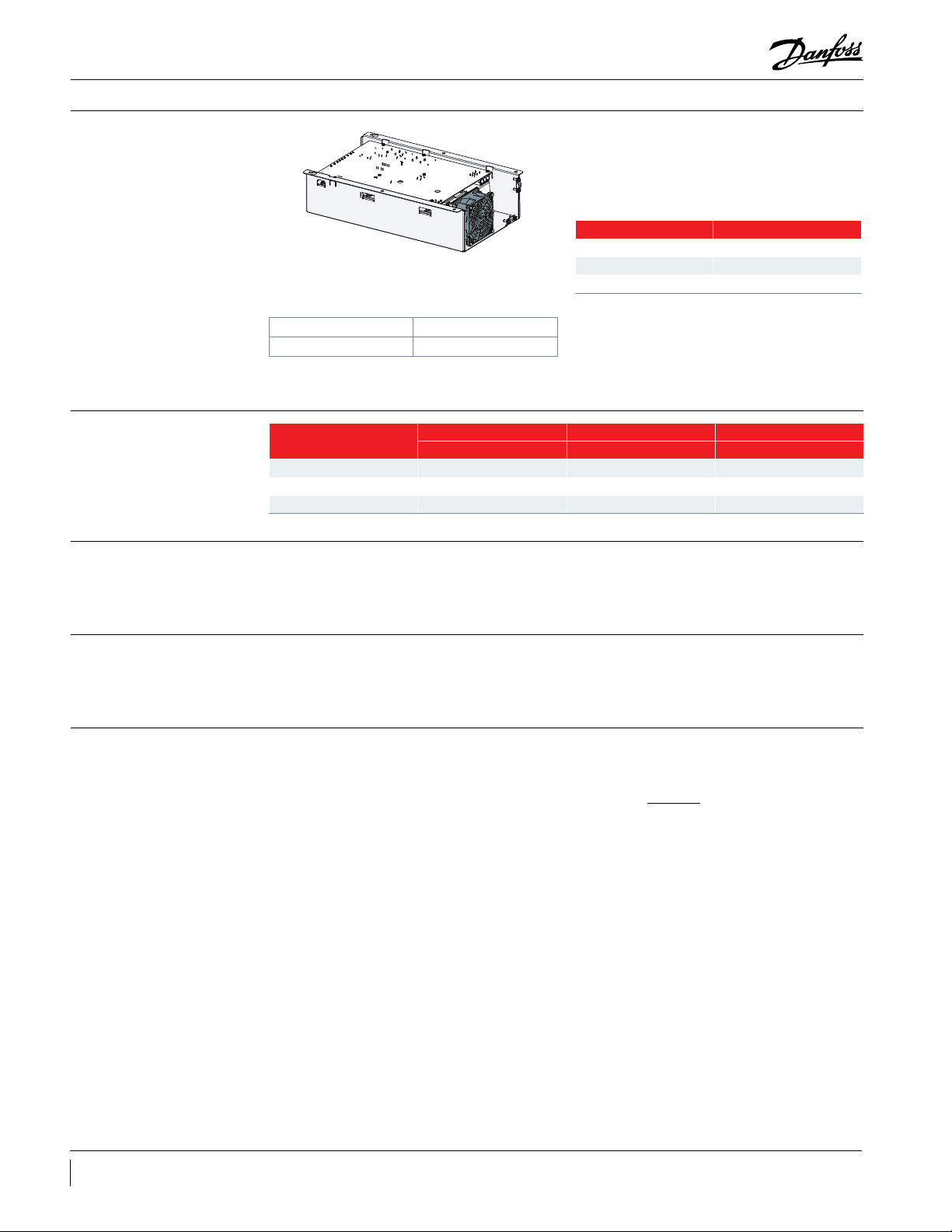
Introduction
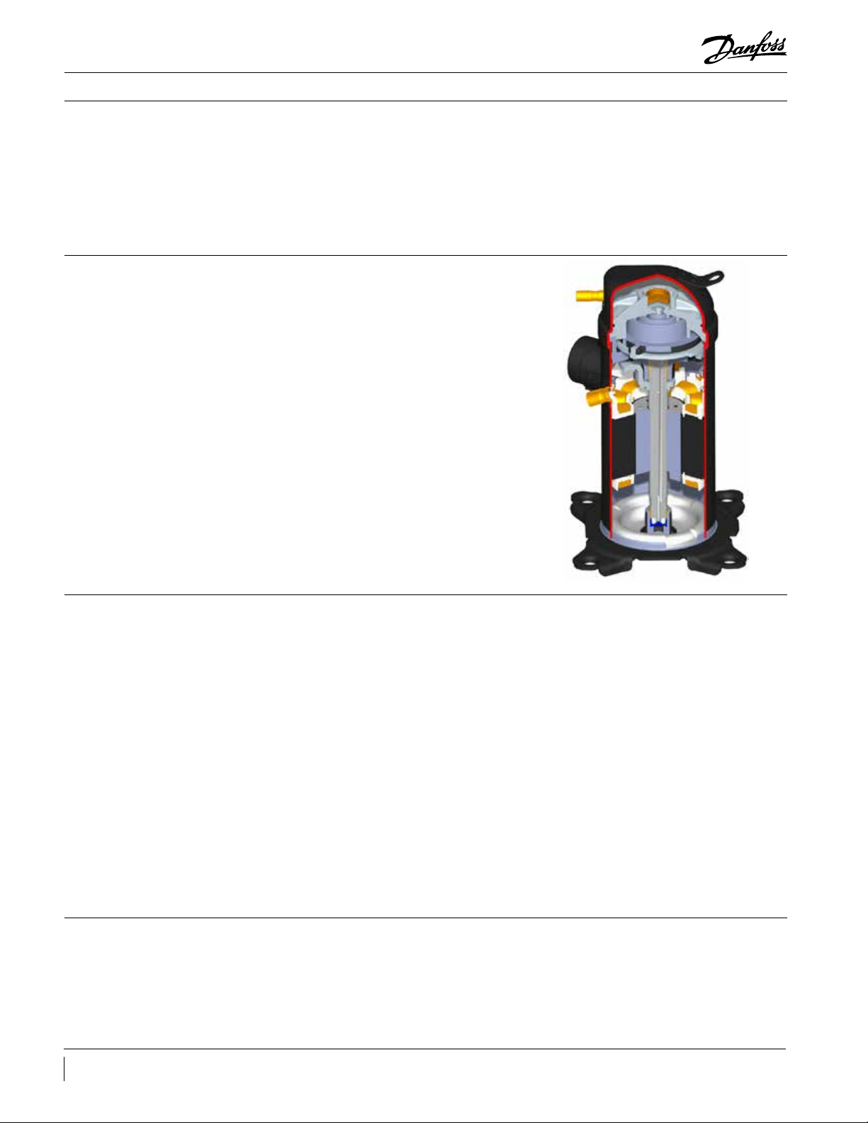
Scroll compressor components
Danfoss VRJ for residential applications
developed by Danfoss is a complete package
consisting of a dedicated variable speed
compressor, variable speed drive, application
controller, electronic expansion valve (EEV), EEV
controller and sensors. Three nominal system
The motor stator is rigidly attached to the shell.
The rotor is shrink-t onto the eccentric shaft. The
shaft is supported by two bearings, one in the
crankcase and the second below the motor.
sizes are available (3, 4 and 5 TR), based on three
compressor models.
These Selection & Application Guidelines focus
on the variable speed scroll compressor.
Compressor size
Performance
Variable speed technology oers more exibility
in compressor selection than xed speed
compressors. Selection of the right variable
speed compressor size can be done by dierent
methods:
• Maximum cooling capacity: select a
compressor size that achieves the peak
load system cooling capacity demand at its
maximum speed.
• Nominal cooling capacity: select a
compressor size that achieves the nominal
system cooling capacity at a rotational
speed of 3000-4200 rpm (50-70Hz).
• Best Seasonal Eciency Ratio: select a
compressor size that achieves the minimum
The Danfoss VRJ compressors referenced in this
guide is a fully compliant scroll and actually
improves with run time in its early commissioning.
system cooling demand at its minimum
speed. Ensure that the compressor is able to
cover the peak load system cooling capacity.
This selection makes the compressor to run
for a maximum of time at part load where
the system eciency is highest.
Danfoss scroll compressors are manufactured
using the most advanced machining, assembly,
and process control techniques. In design of
both the compressor and the factory, very high
standards of reliability and process control
were rst priority. The result is a highly ecient
product with the highest reliability obtainable,
and a low sound level.
A seventy-two hour run-in is recommended to
meet performance expectations.
4 AB141686422149en-US0301
Page 5
Application Guidelines
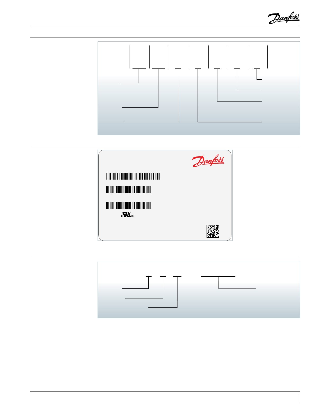
Compressor model designation
Nomenclature
Label
Application,
Family
& Refrigerant
VRJ
Application, Family
& refrigerant
V: Variable speed
R: Residential
J: R410A, PVE lubricant
Swept Volume
Displacement in cc/rev
Model Variation
U: Design optimised for high SEER
Compressor
Model no : VRJ044UKNP6
Serial no :
Tech no : VGK46PHA001
LK2500000333
Swept
Volume
028
Model
Variation
U
245 Max Inverter Driven
Drive Model: 178L002
LR: 12.0 A MAX OPER: 30.0A
Lubricant:PVE / 45 oz/1.33 L
VoltageNMotor
K
MADE IN CHINA
Protection
Equipment
Version
P
Other
Features
6
Other features
6: No other features
Equipment version
P: Brased connections,
spade terminals
Motor protection
N: No internal motor
protection (protection by
drive)
Voltage
K: 420V DCL IPM
Serial number
2020
INVERTER PROTECTED
PROTECTED BY DOMESTIC AND FOREIGN PATENTS
1000000052
12345678A 25B
Year code 8 Digit serial number
Month code
Plant assembly line code
5AB141686422149en-US0301
Page 6

Application Guidelines
Technical specifications
Compressor specications
Performance data
Compressor
model
VRJ028 1.64 51 103 206 240 36 68
VRJ035 2.12 66 133 265 310 45 71
VRJ044 2.65 83 166 332 387 45 71
Conditions
High SEER
conditions
(H)
CHEER
conditions
Heat Pump
conditions
SEER
conditions (I)
Swept
volume
cu.in/rev
Compressor
model
VRJ028 3 Tons
VRJ035 4 Tons
VRJ044 5 Tons
VRJ028 3 Tons
VRJ035 4 Tons
VRJ044 5 Tons
VRJ028 3 Tons
VRJ035 4 Tons
VRJ044 5 Tons
VRJ028 3 Tons 1800 30 21000 1.75 68.5
VRJ035 4 Tons 1800 30 26800 2.23 69.7
VRJ044 5 Tons 1800 30 34500 2.88 70.9
Min speed 30 Hz 60 Hz Max speed
900 rpm 1800 rpm 3600 rpm 4200 rpm
Nominal
Tons
Displacement Oil charge Net weight
oz lb
Compressor speed Compressor capacity
rpm Hz Btu/hr Ton
3600 60 36700 3.06 66.2
4200 70 42700 3.56 64.9
3600 60 46400 3.87 67.6
4200 70 53400 4.45 65.1
3600 60 57800 4.82 68.3
4200 70 68100 5.68 67.0
3600 60 36500 3.04 65.9
4200 70 42300 3.53 64.3
3600 60 46200 3.85 67.3
4200 70 53000 4.42 64.6
3600 60 57900 4.83 68.8
4200 70 68300 5.69 67.5
3600 60 25100 2.09 59.7
4200 70 29300 2.44 58.8
3600 60 31800 2.65 61.0
4200 70 36700 3.06 59.0
3600 60 40200 3.35 62.2
4200 70 47300 3.94 61.2
Compressor
isentropic eciency
Variable speed drive
specications
Bearings lubrication
6 AB141686422149en-US0301
Conditions
High SEER
conditions (H)
CHEER
conditions
Heat Pump
conditions
SEER
conditions (I)
Evaporating
Temperature
(°F)
50 115 20 15
45 100 20 15
30 110 20 15
55 100 20 15
Condensing
Temperature
(°F)
For dedicated variable speed drive specications,
refer to “Danfoss VRJ Installation and Operation
instructions”.
A specic oil pump ensures optimal bearing
lubrication at all compressor speeds. This to have
sucient bearing lubrication at low speeds as well
Superheat
(°F)
Subcooling
(°F)
as avoid excessive Oil Circulation Ratio (OCR) at
high speeds.
Page 7
Application Guidelines
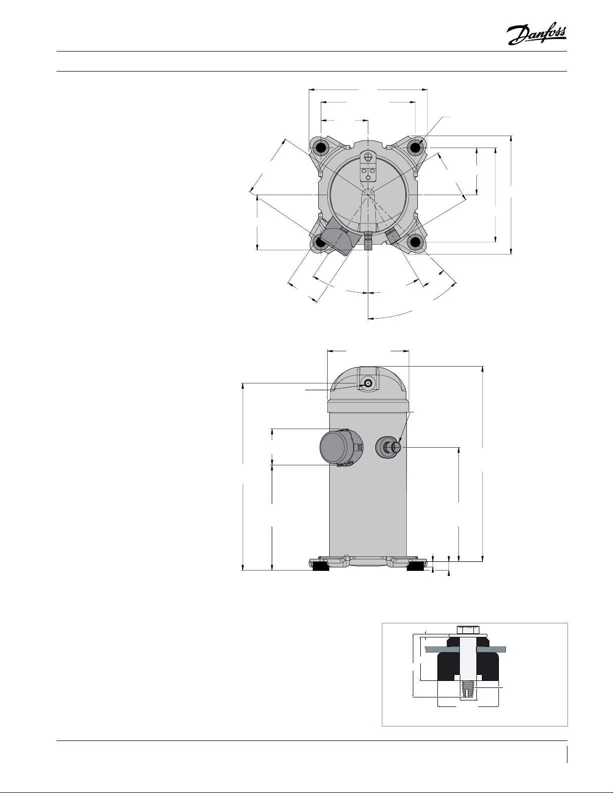
9.40
All dimensions in inch
Dimensions
VRJ 028 - 035 - 044
4.38
5.06
2.74 - 2.80
7.491 - 7.509
3.750
34°
6.438 - 6.515
31°
45°
4.32
14°
4 x Ø 0.75 - 0.78
3.750
9.40
7.491 - 7.509
14.19
Discharge port
1/2” ODF
2.84 - 2.95
7.76
Suction port
3/4” ODF
9.09
0.42
0.75
Mounting grommet
0.067
1.161
1.614
15.53
5/16” - 18 UNC
self tapping
Ø 0.433
Recommended torque for mounting bolts:
8 ft.lbs (±1ft.lbs)
Ø 1.614
7AB141686422149en-US0301
Page 8
Application Guidelines
Electrical data, connections and wiring
Supply Voltage VRJ compressors must not be connected directly
to the mains supply. They must only be powered
through the dedicated Danfoss variable speed
drive.
Compressor model Variable Speed Drive Model
VRJ028 176L7000
VRJ035 176L7001
VRJ044 176L7002
Compressor electrical
specications
LRA (Locked Rotor Amp)
MCC (Maximum Continuous Current)
Winding resistance
Nominal voltage 208-230V – 1Ph – 60Hz
Voltage range 187 – 253 V
Refer to “Danfoss VRJ Installation and Operation
instructions” for more details about supply
voltage.
Compressor model LRA MCC Winding resistance
A A Ohm
VRJ028 10.2 18 0.255
VRJ035 12 23.5 0.210
VRJ044 12 30 0.210
LRA is the higher average current as measured
on a mechanically blocked compressor tested
under nominal voltage. LRA is printed on the
VRJ compressors, the LRA value is low because the
variable speed drive reacts very rapidly (far below
1 second).
nameplate, according to UL requirements. With
The MCC value is the maximum at which
the compressor can be operated in transient
MCC value is measured based on UL conditions
(max load) and at low voltage.
conditions and out of the operating envelope. The
VRJ scroll compressors are equipped with an IPM
(permanent magnet) motor.
temperature ; If the compressor is stabilised at a
dierent value than 77°F, the measured resistance
must be corrected with following formula:
a + t
Winding resistance is the resistance between
indicated terminal pins at 77°F (resistance value ±
7%).
Winding resistance is generally low and it requires
adapted tools for precise measurement. Use
a digital ohm-meter, a ‘4 wires’ method and
measure under stabilised ambient temperature.
R
= R
tamb
77°F
t
: reference temperature = 77°F
77°F
: temperature during measurement (°F)
t
amb
: winding resistance at 77°F
R
77°F
: winding resistance at t
R
tamb
a: Coecient a= 390
a + t
amb
77°F
amb
Winding resistance varies strongly with winding
8 AB141686422149en-US0301
Page 9
Application Guidelines
Electrical data, connections and wiring
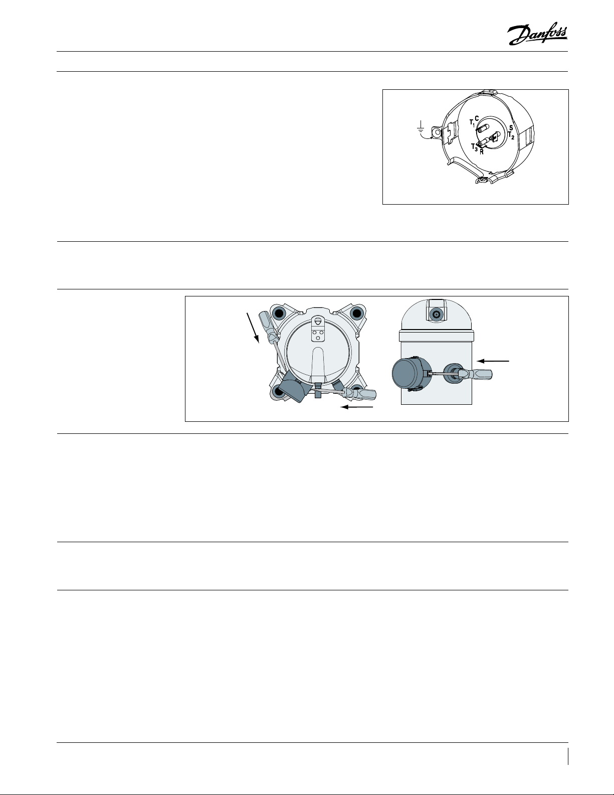
Wiring connections
VRJ scroll compressors will only compress gas
while rotating counter-clockwise (when viewed
from the compressor top).
The drawing shows electrical terminal labelling
and should be used as a reference when wiring the
compressor.
T1, T2 and T3 of the drive and the compressor
must be connected accordingly.
Refer to “Danfoss VRJ Installation and Operation
instructions” for details and cable sizes.
Terminal cover mounting The terminal cover and gasket should be installed
prior to operation of the compressor. The terminal
cover has two outside tabs, 180 degrees apart, that
Terminal cover removal
push
Quick connect spade terminals
P terminal box type
engage the terminal fence. When installing the
cover, check that it is not pinching the lead wires.
push
IP rating
Internal motor protection
Phase sequence and reverse rotation protection
push
The compressor terminal box IP rating according to CEI 529 is IP22 for all models. This IP rating is only
valid when correctly sized cable glands with the same IP rating are applied.
• First numeral, level of protection against contact and foreign objects
2 protection against object size over 1/2 inch (ngers of similar)
• Second numeral, level of protection against water
2 protection against dripping water when tilted up to 15°
VRJ scroll compressors are not equipped with
an internal motor protector. Motor protection
is provided by the variable speed drive. All
The compressor will only operate properly in a
single direction. If electrical connections are done
correctly between the drive and the compressor
terminals (compressor and drive terminals T1, T2
and T3 matching), the drive will provide correct
phase supply to the compressor, and reverse
rotation will be not possible.
motor para-meters are factory preset in order to
guaranty optimal locked rotor or overload current
protection.
If compressor and drive T1, T2 and T3 terminals are
not matching, the compressor can go in reverse
rotation. This results in excessive noise, no pressure
dierential between suction and discharge, and
suction line warming rather than immediate
cooling. The compressor can be rapidly severely
damaged in these conditions.
9AB141686422149en-US0301
Page 10

Application Guidelines
Approvals and certificates
Approval and certicates VRJ scroll compressors comply with the following
approvals and certicates.
Pressure equipment directive 97/23/EC
Low voltage directive 73/23/EC, 93/68/EC
Internal free volume
UL
(Underwriters Laboratories)
Other approvals / certicates Contact Danfoss
Refrigerating uids Group 2
Category PED I
Evaluation module no scope
Manufacturer's declaration of incorporation
ref. EC Machines Directives 98/392/CE
Products Internal free volume at LP side without oil (in.3)
VRJ028 - 035 - 044 179
All models
Contact Danfoss
10 AB141686422149en-US0301
Page 11

Application Guidelines
Operating conditions
Refrigerant and lubricants
General information
PVE
VRJ scroll compressor application range is
inuenced by several parameters which need to
be monitored for a safe and reliable operation.
These parameters and the main
recommendations for good practice and safety
devices are explained hereunder:
When choosing a refrigerant, dierent aspects
must be taken into consideration:
• Legislation (now and in the future)
• Safety
• Application envelope in relation to expected
running conditions
• Compressor capacity and eciency
• Compressor manufacturer
recommendations & guidelines
Polyvinyl ether (PVE) is an innovative refrigeration
lubricant for HFC refrigerant systems. PVE is as
hygroscopic as existing polyolester lubricants
(POE), but PVE does not chemically react with
water; no acids are formed and compressor
evacuation is easier.
Refrigerant and lubricants
Motor supply
Compressor ambient temperature
Application envelope (evaporating
temperature, condensing temperature, return gas
temperature)
Additional points could inuence the nal choice:
• Environmental considerations
• Standardisation of refrigerants and
lubricants
• Refrigerant cost
• Refrigerant availability
The compressor technology applied in Danfoss
VRJ scroll compressors in combination with PVE
lubricant provides the best possible result in
terms of reliability and compressor lifetime.
Residual moisture
Motor supply
Compressor ambient temperature
High ambient temperature
Low ambient temperature
Prior to shipment from the factory, every
compressor is dehydrated, evacuated, and
charged with dry nitrogen. Maximum residual
VRJ scroll compressors can be operated only
connected to the dedicated variable speed
drive, at nominal voltages as indicated in “supply
VRJ scroll compressors can be applied from
-13°F to 125°F ambient temperature. The
compressors are designed as 100 % suction gas
In case of enclosed tting and high ambient
temperature, it is recommend to check the
Although the compressor itself can withstand
low ambient temperature, the system may
require specic design features to ensure safe
moisture levels are 0.0082 oz. for model VRJ028,
and 0.0120 oz. for VRJ035 and VRJ044.
voltage” section. Under-voltage and over-voltage
operation is allowed within the indicated voltage
range.
cooled without need for additional fan cooling.
Ambient temperature has very little eect on the
compressor performance
temperature of power wires and conformity to
their insulation specication.
and reliable operation. See below sections for
recommendations.
11AB141686422149en-US0301
Page 12

Application Guidelines
Operating conditions
Application envelope
The operating envelope for VRJ scroll
compressors is given in the gure below, where
the condensing and evaporating temperatures
represent the range for steady-state operation.
Under transient conditions, such as start-up
and defrost for heat pump applications, the
compressor may operate outside this envelope
for short periods.
The operating limits serve to dene the
envelope within which reliable operations of the
compressor are guaranteed:
-40 -36 -32 -28 -24 -20 -16 -12 -8 -4 0 4 8 12 16 20 24
155
145
135
125
115
105
95
85
75
65
2300 - 2850 RPM
2200 - 3300 RPM
2100 - 3750 RPM
1800 - 4200 RPM
1500 - 4200 RPM
1300 - 4500 RPM
1100 - 4500 RPM
Saturated condensing temp. (°F)
55
45
35
-40 -30 -20 -10 0 10 20 30 40 50 60 70 80
Saturated evaporating temp. (°F)
• Maximum discharge gas temperature: +275°F
• Suction superheat is dedictated by the
minimum sump superheat (see graph p16).
• Maximum superheat of 40°F
• Minimum and maximum evaporating
and condensing temperatures, as per the
operating envelopes.
All the below limits, temperatures and speeds,
are secured by the parameters in the drive and
application controller software’s.
(°C)
2400 RPM Derated
900 - 4500 RPM
70
66
62
58
54
50
46
42
38
34
30
26
22
18
14
10
6
2
(°C)
Maximum discharge gas
temperature
12 AB141686422149en-US0301
The discharge temperature depends mainly on
the combination of evaporating temperature,
condensing temperature and suction gas
superheat and speed. Discharge gas temperature
should be controlled with an insulated sensor
attached to the discharge line, 6 in. from the
compressor shell. Maximum discharge gas
temperature must not exceed 275°F when the
compressor is running within the approved
operating envelope.
Refer to “Danfoss VRJ Installation and Operation
instructions” for connection details, and to
“Sensor Selection Guideline” manual for
selection details and technical brochures about
temperature sensors.
Page 13

Application Guidelines
Operating conditions
High and low pressure protection
Pressure settings
High pressure
Low pressure
Suction and discharge pressure transmitters have
to be installed and connected to the variable
speed drive to ensure the compressor operates
within the application envelope described above.
Refer to “Danfoss VRJ Installation and Operation
instructions” for connection details, and to
“Sensor Selection Guideline” manual for selection
details and technical brochures about pressure
transmitters.
R410A
Working pressure range high side psig 119 - 645
Working pressure range low side psig 28 - 202
Maximum high pressure safety switch setting psig 653
Minimum low pressure safety switch setting
psig 22
: LP safety switch shall never be bypassed
According to UL requirements, a high pressure
safety switch is still mandatory in any system,
even with high pressure transmitters connected
and used via the variable speed drive.
depending on the application and ambient
conditions. The HP switch must either be placed
in a lockout circuit or consist of a manual reset
device to prevent cycling around the high-
pressure limit. If a discharge valve is used, the HP
HP switch settings shall not exceed the maximum
service pressure of any system components. The
switch must be connected to the service valve
gauge port, which must not be isolated.
high-pressure switch can be set to lower values
A low pressure (LP) safety switch is
recommended. Deep vacuum operations of a
scroll compressor can cause internal electrical
arcing and scroll instability. Danfoss scroll
compressors exhibit high volumetric eciency
and may draw very low vacuum levels, which
could induce such a problem. The minimum
low-pressure safety switch (loss of charge safety
switch) setting is given in the above table. Either
the LP safety switch must be a manual lockout
device or an automatic switch wired into an
electrical lockout circuit. The LP switch tolerance
must not allow for vacuum operations of the
compressor.
High pressure ratio
Crankcase heating
Oil return management
Scroll compressors are machines with xed
volume ratio, and operate more eciently
near the design pressure ratio. In the extreme,
do not exceed a 7.5:1 pressure ratio (absolute
discharge pressure to absolute suction pressure)
A crankcase heating function can be provided
by injecting a DC current in the motor of the
compressor, to keep the compressor warm, and
avoid liquid migration during o cycle.
A specic function can be enabled to secure
the oil return to the compressor. When the
compressor is running at minimum speed for
for extended periods. The Danfoss VRJ scroll
compressor is equipped with an internal pressure
relief valve for protection against blocked
condenser and fan failure conditions.
Refer to “Danfoss VRJ Installation and Operation
instructions” for details.
extended periods, every half hour, speed will be
increased to 2400 rpm for a 80 seconds period.
13AB141686422149en-US0301
Page 14

Application Guidelines
Operating conditions
On/o cycling
(cycle rate limit)
Start-up sequence To ensure correct lubrication of all the
The on/o cycling protection is included in the
variable speed drive. There is no need for extra
on/o cycling protection.
mechanical parts, VRJ compressors start with
a dened ramp-up, and stay at a xed speed
for some seconds. Then the compressor speed
increases up to the desired set point according to
capacity request.
14 AB141686422149en-US0301
Page 15

Application Guidelines
U-trap, as short as possible
System design recommendations
General
Essential piping design considerations
Successful application of scroll compressors
is dependent on careful selection of the
compressor for the application. If the compressor
is not correct for the system, it will operate
Proper piping practices should be employed to
ensure adequate oil return, even under minimum
load conditions with special consideration given
to the size and slope of the tubing coming
from the evaporator. Tubing returns from the
evaporator should be designed so as not to trap
oil and to prevent oil and refrigerant migration
back to the compressor during o-cycles.
It is particularly important and critical with
variable capacity systems, where very low
velocities can be achieved for long periods of
time, generating oil return issues.
If the evaporator lies above the compressor, as
is often the case in split or remote condenser
systems, the addition of a pump-down cycle
is strongly recommended. If a pump-down
cycle were to be omitted, the suction line must
have a loop at the evaporator outlet to prevent
refrigerant from draining into the compressor
during o-cycles.
If the evaporator were situated below the
compressor, the suction riser must be trapped so
as to prevent liquid refrigerant from collecting at
the thermal bulb location (see g. 1).
beyond the limits given in this manual. Poor
performance, reduced reliability, or both may
result.
When the condenser is mounted at a higher
position than the compressor, a suitably sized
«U»-shaped trap close to the compressor is
necessary to prevent oil leaving the compressor
from draining back to the discharge side of the
compressor during o cycle. The upper loop also
helps avoid condensed liquid refrigerant from
draining back to the compressor when stopped
(see g. 2). The maximum elevation dierence
between the indoor and outdoor section
cannot exceed 26 feet. System manufacturers
should specify precautions for any applications
that exceed these limits to ensure compressor
reliability.
Piping should be designed with adequate three-
dimensional exibility. It should not be in contact
with the surrounding structure, unless a proper
tubing mount has been installed. This protection
proves necessary to avoid excess vibration, which
can ultimately result in connection or tube failure
due to fatigue or wear from abrasion. Aside from
tubing and connection damage, excess vibration
may be transmitted to the surrounding structure
and generate an unacceptable noise level within
that structure as well (for more information on
noise and vibration, see the section on: “Sound
and vibration management” section.
g.1
max. 13 ft
max. 13 ft
0.5 % slope,
13 ft/s or more
U-trap, as short as possible
26 to 40 ft/s
0.5 % slope,
13 ft/s or more
U-trap
Evaporator
To condenser
g. 2
Upper loop
Condenser
HP
U-trap
LP
3D exibility
15AB141686422149en-US0301
Page 16

Application Guidelines
Saturated suction temp. °F
System design recommendations
Refrigerant charge limit
Reversible heat pump systems
Minimum sump superheat
Scroll compressors can tolerate liquid refrigerant
up to a certain extend without major problems.
However, excessive liquid refrigerant in the
compressor is always unfavourable for service
life. Besides, the installation cooling capacity may
be reduced because of the evaporation taking
place in the compressor and/or the suction line
Transients are likely to occur in reversible heat
pump systems, i.e. a changeover cycle from
cooling to heating, defrost or low-load short
cycles. These transient modes of operation may
lead to liquid refrigerant carryover (or ood
back) or excessively wet refrigerant return
conditions. As such, reversible cycle applications
The minimum sump temperature is in the range
from 10°F to 30°F above saturated suction
Floodback requirement
40
35
instead of the evaporator. System design must be
such that the amount of liquid refrigerant in the
compressor is limited. In this respect, follow the
guidelines given in the section: “Essential piping
design recommendations” in priority.
require specic precautions for ensuring a long
compressor life and satisfactory operating
characteristics. Specic tests for repetitive ood
back are required to conrm whether or not
special system design considerations should be
considered.
temperature. Refer to the ood back test criteria.
Preventing liquid ood back
30
25
Acceptable
20
15
Sump superheat, °F
10
5
0
-10 0 10 20 30 40 50 55
Danfoss recommends the use of an electronic
expansion valve for all air conditioning and heat
pump applications with VRJ compressors. An
Exceptions to the use of EXV’s with Danfoss
VRJ must be approved by Danfoss application
engineering.
EXV has two key benets: it provides modulating
control of the system under varying load
conditions, and it protects the compressors from
ood back during adverse running conditions.
Unacceptable
16 AB141686422149en-US0301
Page 17

Application Guidelines
System design recommendations
Water utilising systems Apart from residual moisture in the system
after commissioning, water could also enter the
refrigeration circuit during operation. Water in
the system shall always be avoided. Not only
because it can shortly lead to electrical failure,
sludge in sump and corrosion but in particular
because it can cause serious safety risks.
Common causes for water leaks are corrosion and
freezing.
Corrosion: Materials in the system shall be
compliant with water and protected against
corrosion.
Loss of charge protection
Oil level checking and top-up
VRJ scroll compressors together with the variable
speed drive include a loss of charge protection
function. This protection is ensured if pressure
In installations with good oil return and line
runs up to 50 ft, no additional oil is required. If
installation lines exceed 50 ft, additional oil may
be needed. 1 or 2% of the total system refrigerant
charge (in weight) can be used to roughly dene
the required oil top-up quantity.
Freezing: When water freezes into ice its volume
expands which can damage heat exchanger
walls and cause leaks. During o periods water
inside heat exchangers could start freezing when
ambient temperature is lower than 32°F. During
on periods ice banking could occur when the
circuit is running continuously at too low load.
Both situations should be avoided by connecting
a pressure and thermostat switch in the safety
line.
and temperature sensors are connected to the
drive.
Always use oil from new cans.
Top-up the oil while the compressor is idle. Use
any accessible connector on the compressor
suction line and a suitable pump.
17AB141686422149en-US0301
Page 18

Application Guidelines
Sound and vibration management
Starting sound level
Running sound level
During start-up transients, it is natural for the
compressor sound level to be slightly higher
than during normal running. Danfoss scroll
VRJ scroll compressors are designed with
optimised discharge ports and wrap geometry
Sound level vs Speed
78
76
74
72
70
68
66
64
62
Sound power level (dBA)
60
58
56
45/130
4200
45/130
3600
Condition (Tsat(suction) / Tsat (discharge) and speed (RPM)
45/100
compressors exhibit very little increased start-up
transient sound.
to reduce the sound level when a compressor is
running.
3600
45/100
2400
45/100
1800
45/100
900
Stopping sound level
Sound generation in a refrigeration system and air conditioning system
Compressor sound radiation
VRJ scroll compressors have very low shutdown
sound due to minimal volume of discharge
volume to push scrolls in reverse at shutdown.
Typical sound and vibration in refrigeration and
air conditioning systems encountered by design
and service engineers may be broken down into
the following three source categories.
Sound radiation: This generally takes an
airborne path.
Mechanical vibrations: These generally extend
For sound radiating from the compressor, the
emission path is airborne and the sound waves
are travelling directly from the machine in all
directions.
The VRJ scroll compressor is designed to be quiet
and the frequency of the sound generated is
pushed into the higher ranges, which not only
are easier to reduce but also do not generate the
penetrating power of lower-frequency sound.
Use of sound-insulation materials on the inside of
unit panels is an eective means of substantially
Due to this small re-expansion, there is no
internal break mechanism required to prevent
reverse spin of the scroll set.
along the parts of the unit and structure.
Gas pulsation: This tends to travel through the
cooling medium, i.e. the refrigerant.
The following sections will focus on the causes
and methods of mitigation for each of the above
sources.
reducing the sound being transmitted to the
outside. Ensure that no components capable
of transmitting sound/vibration within the unit
come into direct contact with any non-insulated
parts on the walls of the unit.
Because of the Danfoss unique design of a full-
suction gas & oil cooled motor, compressor body
insulation across its entire operating range is
possible.
18 AB141686422149en-US0301
Page 19

Application Guidelines
Sound and vibration management
Mechanical vibrations
Speed bypass
Gas pulsation
Vibration isolation constitutes the primary
method for controlling structural vibration. VRJ
scroll compressors are designed to produce
minimal vibration during operations. The use
of rubber isolators on the compressor base
plate is very eective in reducing vibration
being transmitted from the compressor to
the unit. Rubber grommets are supplied with
all Danfoss compressors. Once the supplied
rubber grommets have been properly mounted,
vibrations transmitted from the compressor base
plate to the unit are held to a strict minimum.
In addition, it is extremely important that the
frame supporting the mounted compressor be
of sucient mass and stiness to help dampen
any residual vibration potentially transmitted to
the frame. The tubing should be designed so as
If vibrations still occur at some typical
frequencies, a speed bypass function is available
within the VRJ. This function allows avoiding
The VRJ scroll compressor has been designed
and tested to ensure that gas pulsation has been
optimised for the most commonly encountered
air conditioning pressure ratio. On heat pump
installations and other installations where the
pressure ratio lies beyond the typical range,
testing should be conducted under all expected
to both reduce the transmission of vibrations to
other structures and withstand vibration without
incurring any damage. Tubing should also be
designed for three-dimensional exibility.
During unit development, the complete
compressor speed range should be covered, in
order to dene if abnormal vibrations occur or
not. As ultimate solution, speed bypass can be
applied.
For more information on piping design, please
see the section entitled “Essential piping design
considerations”.
some frequency ranges and avoiding vibrations
to occur. Refer to “Danfoss VRJ Installation and
Operation instructions” for setting details.
conditions and operating congurations to
ensure that minimum gas pulsation is present. If
an unacceptable level is identied, a discharge
muer with the appropriate resonant volume
and mass should be installed. This information
can be obtained from the component
manufacturer.
19AB141686422149en-US0301
Page 20

Application Guidelines
Installation
Each VRJ scroll compressor is shipped with
printed Instructions for installation.
System cleanliness
Compressor handling and storage
The refrigerant compression system, regardless
of the type of compressor used, will only provide
high eciency and good reliability, along with a
long operating life, if the system contains solely
the refrigerant and oil it was designed for. Any
other substances within the system will not
improve performance and, in most cases, will be
highly detrimental to system operations.
The presence of non-condensable substances
and system contaminants, such as metal
shavings, solder and ux, has a negative impact
on compressor service life. Many of these
contaminants are small enough to pass through a
mesh screen and can cause considerable damage
within a bearing assembly. The use of highly
hygroscopic PVE oils in R410A compressors
requires that the oil be exposed to the
atmosphere just as little as possible.
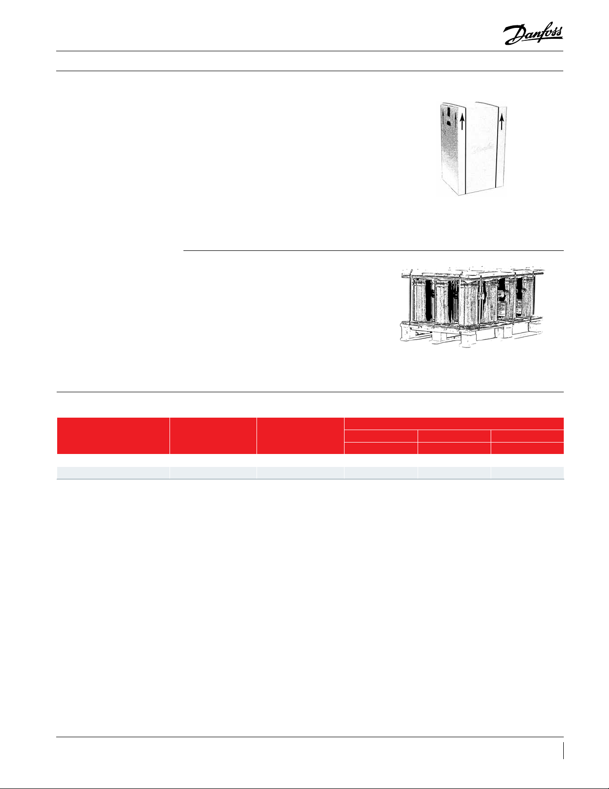
Compressors are provided with a lifting lug. This
lug should always be used to lift the compressor.
Once the compressor is installed, the lifting
lug should never be used to lift the complete
installation. The compressor must be handled
System contamination is one of main factors
aecting equipment reliability and compressor
service life. It is important therefore to take
system cleanliness into account when assembling
a refrigeration system.
During the manufacturing process, circuit
contamination may be caused by:
• Brazing and welding oxides,
• Filings and particles from the removal of
burrs in pipe-work,
• Brazing ux,
• Moisture and air.
Consequently, when building equipment and
assemblies, the following precautions must be
taken: never drill holes into the pipe-work after
installation.
with caution in the vertical position, with a
maximum inclination of 15° from vertical. Store
the compressor between -30°F and 120°F, not
exposed to rain or corrosive atmosphere.
Compressor mounting
Compressor holding charge
Tube brazing procedure
Brazing material
Maximum inclination from the vertical plane,
while operating must not exceed 7 degrees.
All compressors are delivered with 4 rubber
Each compressor is shipped with a nominal dry
nitrogen holding charge between 6 psi and 10
psi, and is sealed with elastomeric plugs. The
plugs should be removed with care to avoid oil
loss when the holding charge is released. Remove
the suction plug rst and the discharge plug
Do not bend the compressor discharge or suction
lines or force system piping into the compressor
connections, because this will increase
For copper suction and discharge ttings, use
copper-phosphorus brazing material. Sil-Fos® and
other silver brazing materials are also acceptable.
grommets and metal sleeves. Compressors must
always be mounted with these grommets.
afterwards. The plugs shall be removed only
just before connecting the compressor to the
installation in order to avoid moisture entering
the compressor. When the plugs are removed, it
is essential to keep the compressor in an upright
position to avoid oil spillage.
stresses that are a potential cause of failure.
Recommended brazing procedures and material,
are described on following page.
If ux is required for the brazing operation, use
coated rod or ux core wire. To avoid system
contamination, do not brush ux on.
20 AB141686422149en-US0301
Page 21
Application Guidelines
Installation
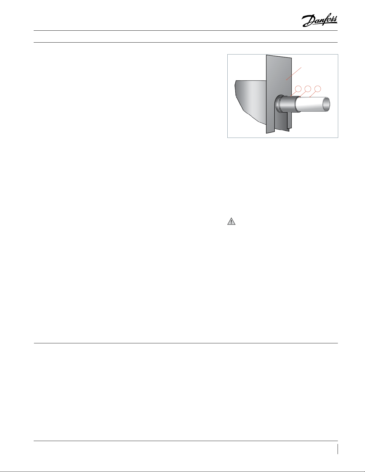
Compressor connection
When brazing the compressor ttings, do not
overheat the compressor shell, which could
severely damage certain internal components
due to excessive heating. Use of a heat shield
and/or a heat-absorbent compound is highly
recommended. For brazing the suction and
discharge connections, the following procedure
is advised:
• Make sure that no electrical wiring is
connected to the compressor.
• Protect the terminal box and compressor
painted surfaces from torch heat damage
(see diagram).
• Use only clean refrigeration-grade copper
tubing and clean all connections.
• Purge nitrogen or CO2 through the
compressor in order to prevent against
oxidation and ammable conditions. The
compressor should not be exposed to the
open air for extended periods.
• Use of a double-tipped torch is
recommended.
• Apply heat evenly to area A until the brazing
temperature is reached. Move the torch
to area B and apply heat evenly until the
brazing temperature has been reached there
as well, and then begin adding the brazing
material. Move the torch evenly around
the joint, in applying only enough brazing
material to ow the full circumference of the
joint.
• Move the torch to area C only long enough
to draw the brazing material into the joint,
but not into the compressor.
• Remove all remaining ux once the joint has
been soldered with a wire brush or a wet
cloth. Remaining ux would cause corrosion
of the tubing.
Heat shield
C B A
Ensure that no ux is allowed to enter into the
tubing or compressor. Flux is acidic and can cause
substantial damage to the internal parts of the
system and compressor.
The PVE oil used in VRJ compressors is highly
hygroscopic and will rapidly absorb moisture
from the air. The compressor must therefore not
be left open to the atmosphere for a long period
of time. The compressor tting plugs shall be
removed just before brazing the compressor.
Before eventual unbrazing the compressor
or any system component, the refrigerant charge
must be removed from both the high and low
pressure sides. Failure to do so may result in
serious personal injury. Pressure gauges must be
used to ensure all pressures are at atmospheric
level.
For more detailed information on the appropriate
materials required for brazing or soldering, please
contact the product manufacturer or distributor.
For specic applications not covered herein,
please contact Danfoss Commercial Compressors
for further information.
Vacuum evacuation and moisture removal
Moisture obstructs the proper functioning
of both the compressor and the refrigeration
system.
Air and moisture reduce service life and
increase condensing pressure, which causes
abnormally high discharge temperatures that
are then capable of degrading the lubricating
properties of the oil. The risk of acid formation
is also increased by air and moisture, and this
condition can also lead to copper plating. All
these phenomena may cause both mechanical
and electrical compressor failures. The typical
method for avoiding such problems is a vacuum
pump-down executed with a vacuum pump, thus
creating a minimum vacuum of 0.02 in Hg (500
µm Hg). Please refer to Bulletin “Vacuum pump
down and dehydration procedure”.
Be sure to follow all government regulations
regarding refrigerant reclamation and storage.
21AB141686422149en-US0301
Page 22

Application Guidelines
Installation
Liquid line lter driers A properly sized lter drier is required for all
Danfoss scroll applications. Danfoss recommends
DML (100% molecular sieves) driers for HFC
refrigerants R410A with PVE oil. For servicing
of existing installations where acid formation is
present the Danfoss DCL solid core lter driers
Refrigerant charging
Insulation resistance and dielectric strength
It is recommended that system charging be
done using the weighed charge method, adding
refrigerant to the high side of the system.
Charging the high and low sides of a system with
gas simultaneously at a controlled rate is also an
acceptable method.
Insulation resistance must be greater than 1
megohm when measured with a 500 volt direct
current megohm tester.
Each compressor motor is tested at the factory
with a high potential voltage (hi-pot) that
exceeds the UL requirement both in potential
and in duration. Leakage current is less than 0.5
mA.
VRJ scroll compressors are congured with
the pump assembly at the top of the shell,
and the motor below. As a result, the motor
containing activated alumina are recommended.
The drier is to be over sized rather than under
sized. When selecting a drier, always take into
account its capacity (water content capacity),
the system refrigeration capacity and the system
refrigerant charge.
Never exceed the recommended system charge
mentioned by the unit manufacturer, and never
charge liquid to the low pressure side.
can be partially immersed in refrigerant and
oil. The presence of refrigerant around the
motor windings will result in lower resistance
values to ground and higher leakage current
readings. Such readings do not indicate a faulty
compressor, and should not be cause for concern.
In testing insulation resistance, Danfoss
recommends that the system be rst operated
briey to distribute refrigerant throughout the
system. Following this brief operation, retest the
compressor for insulation resistance or current
leakage.
Compressor replacement after motor burn out
If there has been a motor burnout follow the
evacuation procedure described on previous
page. Remove and replace the liquid line lter
drier and install a Danfoss type DAS burnout drier
of appropriate capacity.
Refer to the DAS drier instructions and technical
information on correct use and monitoring of the
burnout drier and the liquid line and suction line
lter driers.
22 AB141686422149en-US0301
Page 23
Application Guidelines
Packaging
Single pack
Ordering information and packaging
Compressors are packed individually in a
cardboard box. They can be ordered in any
quantity. Minimum ordering quantity = 1.
As far as possible, Danfoss will ship the boxes on
full pallets of 9 compressors.
Each box contains following accessories:
• 4 grommets
• 4 assemblies of self tapping US thread bolts,
washers and sleeves
Industrial pack
Ordering code numbers
Compressor model
Single pack Yes 1 120G0283 120G0291 120G0299
Industrial pack Yes 12 120G0284 120G0292 120G0300
Compressors are not packed individually but are
shipped all together on one pallet. They can be
ordered in quantities of full pallets only, multiples
12 compressors.
Industrial pack pallet, with mounting hardware,
contains following accessories:
• 4 grommets per compressor
• 4 sleeves per compressor
Mounting hardware
included
Qty of compressors
Code number
3 Tons 4 Tons 5 Tons
VRJ028 VRJ035 VRJ044
23AB141686422149en-US0301
Page 24
Danfoss Commercial Compressors
Danfoss Inverter Scrolls
is a worldwide manufacturer of compressors and condensing units for refrigeration and HVAC applications. With a wide range of
high quality and innovative products we help your company to find the best possible energy efficient solution that respects the
environment and reduces total life cycle costs.
We have 40 years of experience within the development of hermetic compressors which has brought us amongst the global
leaders in our business, and positioned us as distinct variable speed technology specialists. Today we operate from engineering
and manufacturing facilities spread across three continents.
Danfoss Turbocor Compressors
Our products can be found in a variety of applications such as rooftops, chillers, residential air conditioners,
heatpumps, coldrooms, supermarkets, milk tank cooling and industrial cooling processes.
http://danfoss.us.com
Danfoss Commercial Compressors, BP 331, 01603 Trévoux Cedex, France | +334 74 00 28 29
AB141686422149en-US0301
Danfoss Scrolls
Danfoss Optyma Condensing Units
Danfoss Maneurop Reciprocating Compressors
Secop Compressors for Danfoss
© Danfoss | DCS | 2020.12
 Loading...