

Page 1
Data Sheet
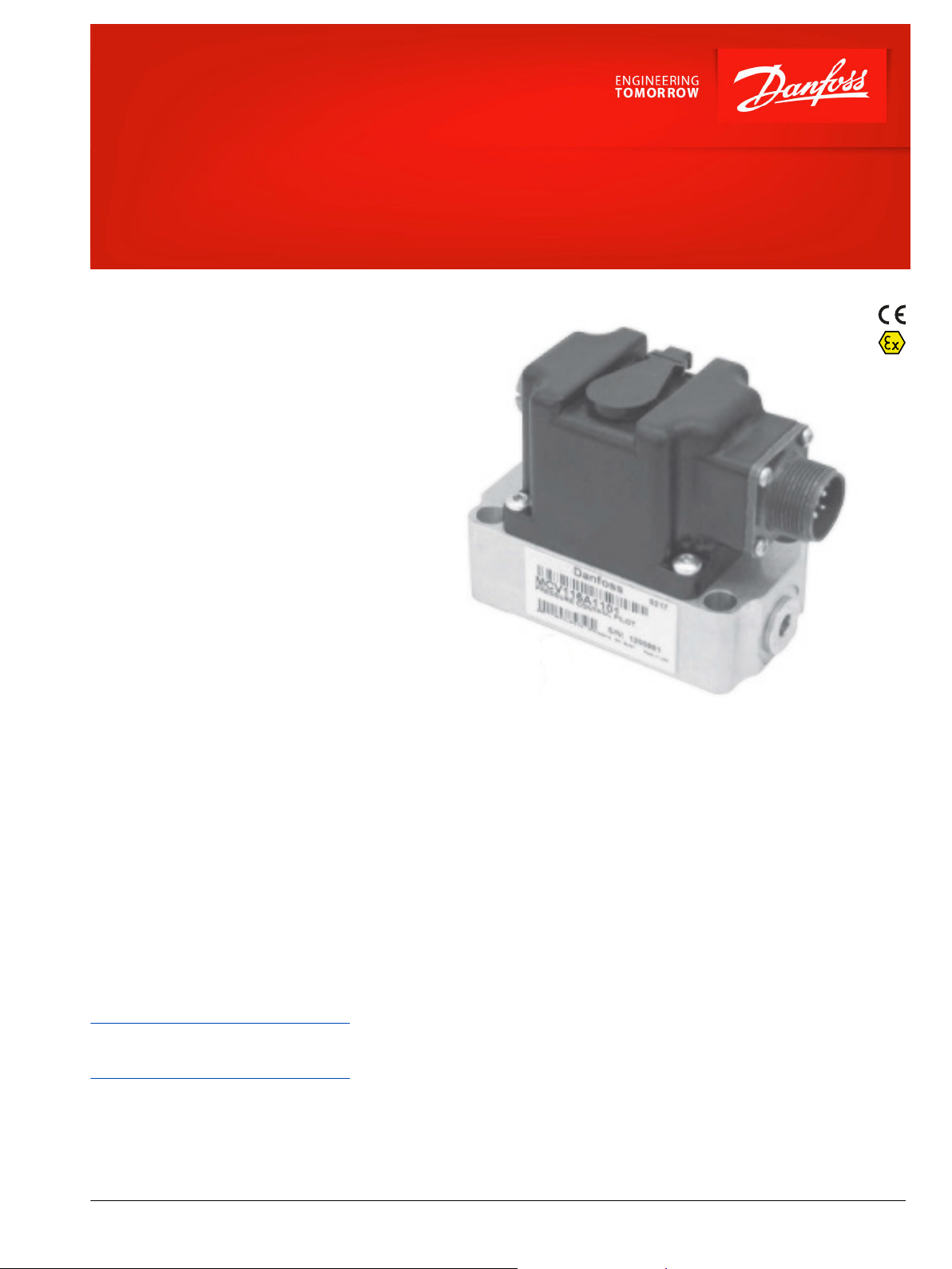
Intrinsically Safe Pressure Pilots Control
Series 90
For more than 40 years, Danfoss has been developing
state-of-the-art components and systems for mobile
machinery used in off -highway operations around
the world. We have become a preferred supplier by
offering the best of what really matters: The hardware
inside your vehicle application.
This line of Intrinsically Safe Pressure Control Pilots
receives a low current input signal from a variety of
machine controllers and converts the current signal
into a proportional differential pressure signal
suitable to control larger hydraulic equipment in
hazardous locations. The intrinsically safe controls can
be added to a Series 90 pump as a standard option or
purchased separately.
Danfoss offers five different models of intrinsically
safe pressure control pilots to accommodate a variety
of standard industrial process controllers. Various
combinations of hydraulic nozzle sizes and coil
resistances yields a relationship between electrical
current (input) and hydraulic differential pressure
(output).
Features
•
Standard manual override
•
Withstands mobile equipment vibration
and shock conditions
•
Controls both pilot-operated pumps/
motors and main spool valves
•
Standard MS-style connector
•
Self-contained pressure feedback
•
Constant scale factor with varying pilot
pressure
•
Can be used in either closed loop or
open loop systems
Comprehensive technical literature online
at powersolutions.danfoss.com
©
Danfoss | May 2016 L1317823 | AI00000178en-US0106 | 1
Page 2
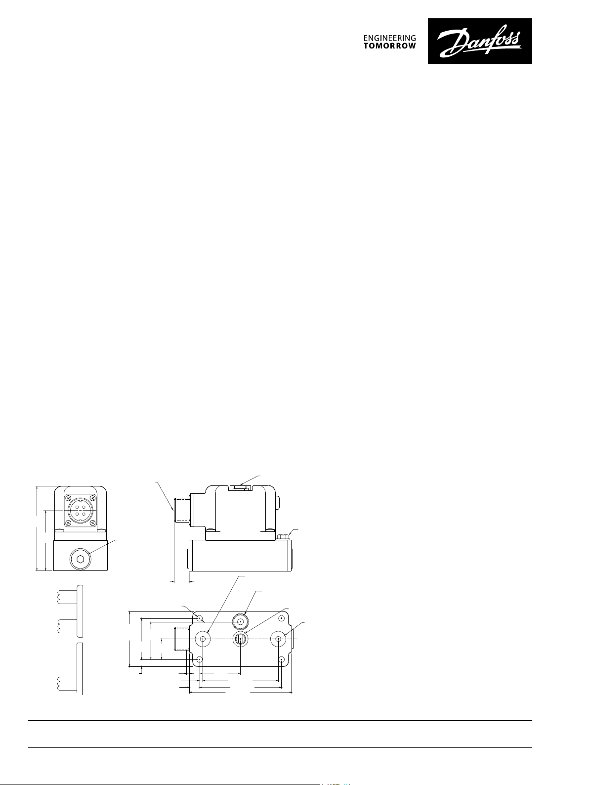
Specifications
MS Connector
Manual Operator
Output Port - C1 4,8 (0.19) Dia.
12,8 (0.50) O.D. X 1,78 (0.07) O-ring
Pressure Port Thru Filter 5,6 (0.22) Dia.
12,8 (0.50) O.D. X 1,78 (0.07) O-ring
Return Port 4,8 (0.19) Dia.
12,8 (0.50) O.D. X 1,78 (0.07) O-ring
Output Port - C2 4,8 (0.19) Dia.
12,8 (0.50) O.D. X 1,78 (0.07) O-ring
38,1
(1.50)
70,1 (2.76)
76,2 (3.00)
95,2 (3.75)
2,5 (0.10) (2)
3,0 (0.12)
9,5 (0.38)
6,3
(0.25)
50,8
(2.00)
MAX
38,1
(1.50)
34,9
(1.375)
19,0
(0.75)
5,5 (0.217) DIA (4)
12,7
(0.50)
Intrinsically
Safe Device
Enclosure
Grounding
Terminal
P108 659E
A
B
C
D
A
B
C
D
Dual Coil
Single Coil
Upper Coil
Lower Coil
Dimensions mm (inches)
78,7
(3.10)
56,1
(2.21)
17,5 DIA (2)
(0.69)
NEC 500 Rating: Exi, Class I, Division 1, Groups C & D, T4
•
Exi – Intrinsically Safe Explosion Protected
•
Class I – Gas applications as defined by Gas Group Designation
•
Division 1 – Area Classification, Gases defined by Gas Group Designation may be present more than 1000 hours per year
•
Gas Group Designation C & D – Approved for use in Ethylene and Propane Applications
•
T4 – This equipment will not exceed 135°C under normal operating conditions
NEC 505 Rating: Class I, Zone 0, Ex ia / AEx ia, Gas Group IIB, T4
•
Class I – Gas applications as defined by Gas Group Designation
•
Zone 0 – Area Classification, Gases defined by Gas Group Designation may be present more than 1000 hours per year
•
Ex ia / AEx ia – Intrinsically Safe Explosion Protected
•
Gas Group Designation IIB - Approved for use in Ethylene and Propane Applications
•
T4 – This equipment will not exceed 135°C under normal operating conditions
ATEX Rating per IEC 60079-11: Equipment Group II, Equipment Category 1, Environment G, Ex, ia, IIB, T4
•
Equipment Group II – Non-Mining Applications
•
Equipment Category 1 – Hazardous material defined by Environment Designation may be present more than 1000 hours per year
•
Environment G – Gases defined by Gas Group Designation
•
Ex – Explosion Protected Equipment
•
ia – Intrinsically Safe Protection Method
•
Gas Group Designation IIB - Approved for use in Ethylene and Propane Applications
•
T4 - This equipment will not exceed 135°C under normal operating conditions
IECEx Rating per IEC 60079-11: Ex ia, Gas Group IIB, T4 - Temperature Rating, Ga - Zone 0
•
Ex – Explosion Protected Equipment
•
ia – Intrinsically Safe Protection Method
•
Gas Group Designation IIB - Approved for use in Ethylene and Propane Applications
•
T4 – This equipment will not exceed 135 deg C under normal operation conditions
•
Ga – Area Classification, Gases defined by Gas Group Designation may be present more then 1000 hours per year
Schematic
Danfoss can accept no responsibility for possible errors in catalogues, brochures and other printed material. Danfoss reserves the right to alter its products without notice. This also applies to products
already on order provided that such alterations can be made without changes being necessary in specifications already agreed.
All trademarks in this material are property of the respective companies. Danfoss and the Danfoss logotype are trademarks of Danfoss A/S. All rights reserved.
2 | © Danfoss | May 2016 L1317823 | AI00000178en-US0106
 Loading...