

Page 1

Gateway InterBus-S
Part 1 ■ Overview . .... ..... ..... .... ..... ..... ..... ..... .... ..... ..... ..... .... ..... .....2
Part 2 ■ P roperties of PROFIBUS-DP ...... ..... .... .... .... .... .... .... ..... ..3
Configuration of the fr equency converter . . .. .. .. .... . .. .. .. .... . .. .. ..4
Notes concerning pr ogramming ............................................5
Control word . .. . . . . . . .. . . . . . . ... . . . . . . ... . . . . . . .. . . . . . . ... . . . . . . .. . . . . . . ... . . . .5
Reference/Actual value . .. .. . . .. . . .. . . .. . . .. . . .. . . .. . . .. . . .. .. . . .. . . .. . . ..5
Parameterization . . .. . . .. . . .. . .. . . .. . . .. . .. .. . .. .. . . .. . .. .. . .. .. . . .. . .. . . .. . . .5
Parameter interface in Write.Request . . . . . . . . . . . . . . . . . . . . . . . . . . . . . .6
Parameter interface in Read.Request . .. .. .. . .. . .. . .. ... .. ... .. ...7
Part 3 ■ Properties of the Interbus-S . .. . . . .. . . . .. . . . .. . . . . . . . . . . .. . . . .. . . . .. . . .9
ID-Code . ......... ....... ......... ....... ......... ....... ................ ................9
Length codes . ..... ...... ...... ..... ...... ...... ...... ...... ...... ..... ...... ...... ..9
PCP Communication ...........................................................10
Communication objects . .. .. ........ .. .. .. ....... .. .. .. ........ .. .. .. .10
Communication re fe rence list ........ ...... ...... ...... ...... ...... ...... ..13
Error reports in PCP Communication . .... .. ..... .. .... .. .... .. .... .. ..13
Contents
English Deutsch
Part 4 ■ Technical data .. . .. . .. . . .. . .. . .. . . .. . .. . .. . . .. . .. . .. . . .. . .. . .. . . .. . .. . . .. . .14
Example of installation . . . . .. . . .. . . . . . . .. . . . . . . .. . .. . .. . . .. . . . . . . .. . . . . . . .. . . . .14
Connection of the PROFIBUS bus wire. .. ...... .. .. .. .. .. ...... .. .. ..15
Connection of the Interbus-S bus wire . . . .. . . . .. . . . .. . . . .. . . . .. . . . . .. .15
Messages ............................................................................16
Operating units . . . . . . . . .. . . . . . . .. . . . . . . .. . . . . . . .. . . . . . . .. . . . . . . .. . . . . . . .. . . . . . . .. . .16
Terminals and connectors . .. . .. . .. . .. . .. . .. . .. . .. . .. . .. . .. . .. . .. . .. . .. . .. . ..16
Housing ............... .................... .................... ................. ... .. ..16
Part 5 ■ Example of program for Siemens S5-115U ...................17
■ Index . .. .. . .. . .. . .. . .. .. . .. . .. . .. .. . .. . .. . .. . .. .. . .. . .. . .. .. . .. . .. . .. . .. .. . .. . ..33
MG.10.G1.51 – VLT i s a r egister ed Danfoss trademark
1
Page 2
■
Overview
The purpose of the InterBus-S /
PROFIBUS-DP-Gateway is to enable the
®
Danfoss VLT
Overview
5000 Frequency Converter
to be operated with the Field Bus system
InterBus-S. For this purpose, the
Gateway converts the InterBus-S
Telegrams to PROFIBUS-DP-T elegrams,
which are then transmitted to the VLT
Reporting back occurs in the same way.
The Gateway converts the PROFIBUS-
®
DP-T elegrams from the VLT
, which are
then tranmitted to the master via the
InterBus-S.
Gateway InterBus-S
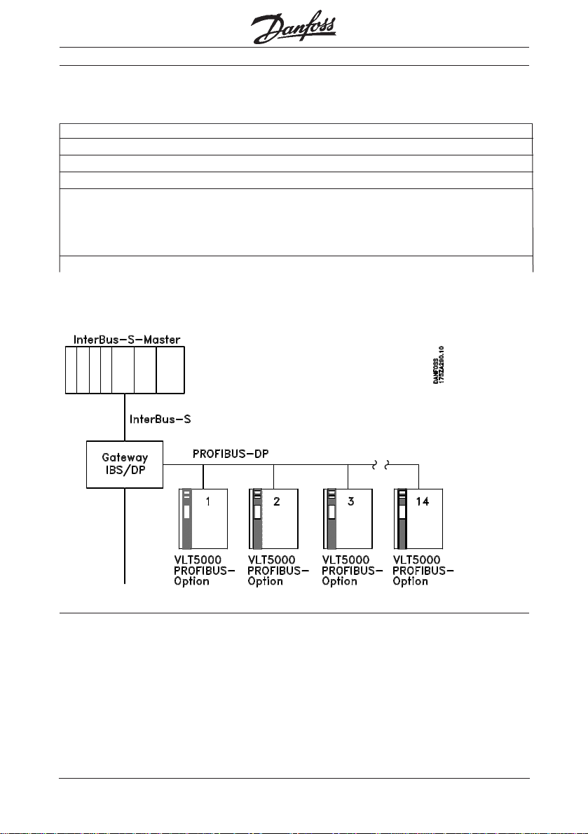
The Gateway enables connection of up to
®
5000 with a PROFIBUS Option
14 VLT
Card. The Gateway sends continuous information of the selected PPO Type with
the actual pr ocess data block and the
actual parameter block to the VLTs .
®
.
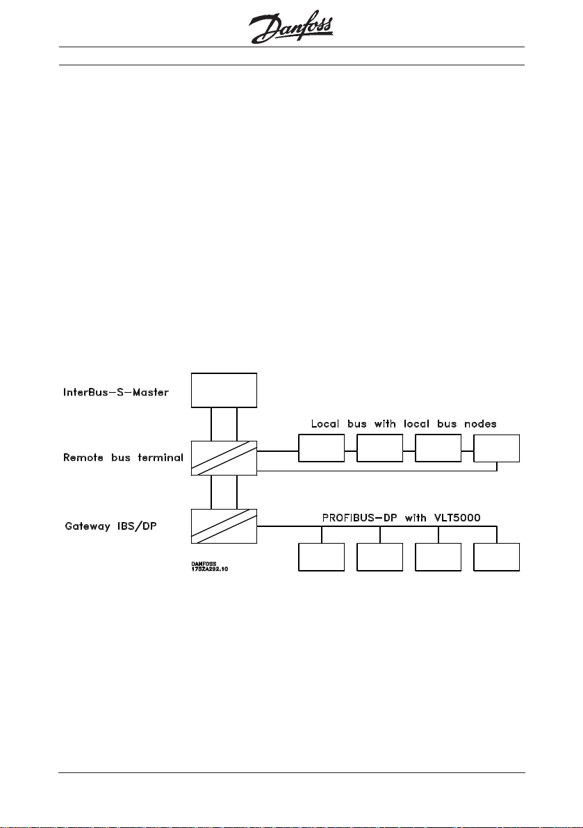
As is usual with InterBus-S, connection of
the Gateway occurs in the form of a
r emote bus participant. However, t hi s
does not convert to the InterBus-S Local
Bus, but to PROFIBUS-DP. This also
means that the well-known limitations of
the local buses, such as max. 8 nodes,
r eady-made bus wire, maximum extension
8 metres, etc., no longer apply.
For communication on the PROFIBUS-DP,
ther e is a choice between PPO Types 1
( P rocess data and parameter interface) or
PPO T ypes 3 (process data only). Process
data is handled as I/Os, i.e. it is available
for the user in the I/O-ar ea of the PLC and
is transmitted with
2
every InterBus-S-cycle.
®
Parameterization of the VLT
via the parameter interface is ef fected via PCP Communication.
MG.10.G1.51 – VLT is a r egister ed Danfoss trademark
Page 3

■
P roperties of the PROFIBUS-DP
A maximum of 14 VLTs can be linked up using the PPO Type1 (12Byte) or the PPO
Type3 (4Byte). The selection of PPO Type
goes for all VLTs; mixed operation is not
permissible and will lead to an err or
report.
The InterBus-S in-/output data is
p r ojected on the PROFIBUS-DP without
any interpr etation being of f ered. W ith one
exception, bit 10 of the contr ol wor d
(CW), is inverted. This ensur es that when
the PLC moves to Stop and resets all
outputs, the connected VLT s will stop,
too; also, when the InterBus-S
communication starts, it is ensur ed that
®
the VLT
5000 remain stopped.
Gateway InterBus-S
The PPO Type1 allows parameterization of
the VLTs , r etrieval of all values and parameters - including fault and diagnostic
data, as well as contr ol of the VLT
reporting back on its actual state.
The PPO Type3, on the other hand, allows
only control and r eporting back on the
®
state of the VLT
.
With respect to the functioning and handling of the parameter interface in PPO
Type1, please r efer to the manual on
PROFIBUS Option Card s for VLT
The baudrate on the PROFIBUS-DP is
1.5Mbaud, which means that the
maximum bus cable length is 100 m.
Further information is available fr om the
PROFIBUS manual for VLT
®
5000.
®
with
®
5000.
P roperties of PROFIBUS-DP-Page
English Deutsch
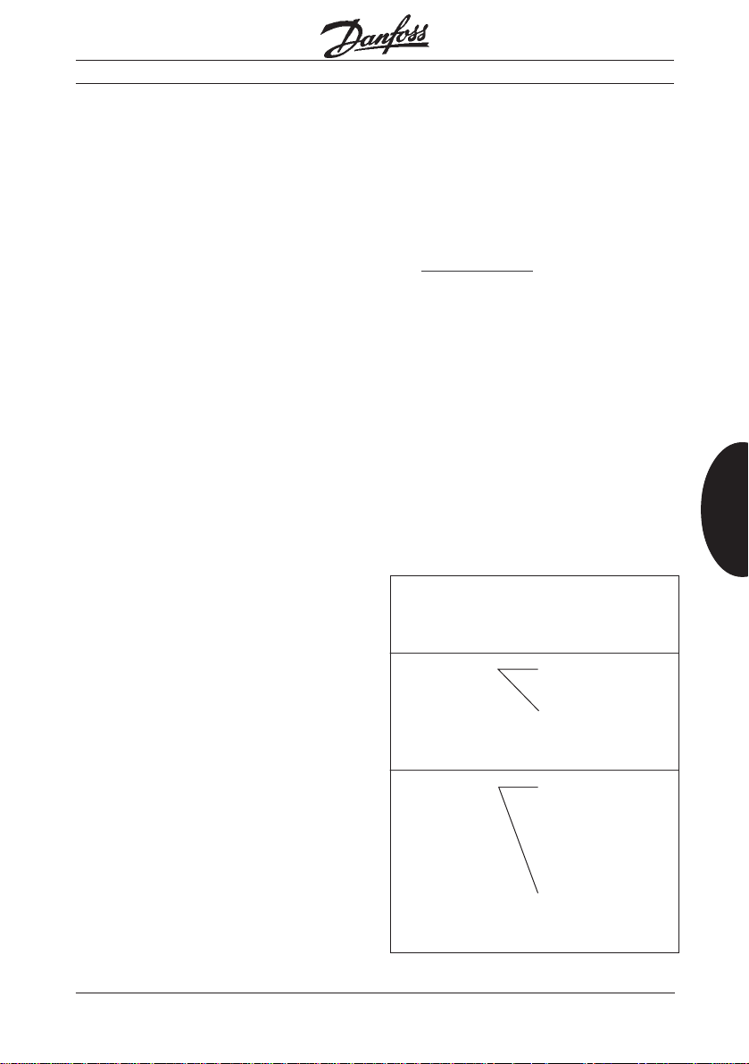
!!! IMPORTANT !!!
Before inserting the PROFIBUS Option Car d, the VLT® should be tur ned on and
parameter 620 should be set to "Initialize". Subsequently, remove the power and
insert the PROFIBUS Option Card. When the unit is turned back on, new
i ni ti al iz at io n is e ffected automatically. Be aware that all parameters will be set to
Factory setting!
If this sequence is not possible, or if the PROFIBUS Option Card has alr eady
been inserted, the keys DISPLAY/STATUS + MENU + OK must be pressed
simultaneously before tur ning on the VLT
keep the three keys pr essed until the message "Manual Initialize" appears in the
bottom line of the display window (see page 136 in MG.50.AX.02).
MG.10.G1.51 – VLT i s a r egister ed Danfoss trademark
®
; subsequently, t u rn on the power and
3
Page 4

Gateway InterBus-S
■
Configuration of the frequency
converter
The following parameters are to be set
or checked, respectively:
Parameter 502-508
Motor coasting, quick-stop, DCbraking, start, reversing, reset, setup
selection, selection of digital refer ence,
this is wher e to decide if contr ol is going
to be via "BUS" only or via "Digital In-
P roperties of PROFIBUS-DP
put" only, or via a combination of the
two. In the case of BUS-selection only,
all parameters should be set to "BUS" at
this point.
Parameter 512
Telegram profile
this is wher e to select the telegram Pr of il e, the profiles ar e descriped in the
PROFIBUS manual for VLT
Danfoss recommend to use Danfoss
profile.
Parameter 801
Baudrate
enter the Bus-Baudrate selected for your
Gateway, or leave the rate at "1.5
MBAUD". At present, the Gateway
baudrate has been set at a fixed rate of
1.5Mbaud.
Parameter 800
FMS/DP-selection,
this is wher e to set "DP"; This is the
factory setting.
Parameter 803
Bus time out,
this time selection determines the delay
The parameters set on the VLT
are not activated until the
power supply has been cut off
and re-cycled.
®
5000.
after a BUS drop-out befor e a r eaction
fr om the fr equency converter is to ensue.
Parameter 804
Bus time out function,
select the r eaction after a BUS drop-out.
Parameter 904
PPO select,
enter the telegram desired, e.g. for PPO
Type1 enter "PPO type1", for PPO Type3
enter "PPO Type3". The PPO types ar e
descriped in the PROFIBUS manual for
®
VLT
5000.
Parameter 918
Station address,
this is wher e the station addr ess is
selected. The range of operation of the
Gateway is from 1-14, with attention
having to be given to thr oughgoing
addressing. The address range basically
begins at "1" and ends at the address of
the maximum number of units available.
This physical position at the BUS has no
influence on addressing.
Parameter 927
Access to parameter change,
this is wher e to select whether the parameter can be altered via the BUS,
("Enable"), or whether this possibility is to
be disabled ("Disable") .
Parameter 928
to p rocess contro l ,
like 927, although this is wher e i t i s t o b e
decided whether control i s going to be effected via the PROFIBUS ("Enable") o r
not ("Disable" ).
®
All other parameters are to be set in
accordance with the intended application,
as described in the product manual.
4
MG.10.G1.51 – VLT is a r egister ed Danfoss trademark
Page 5
Notes concerning programming:
■
The fr equency converter can now be controlled via the BUS; this is ef fected simply
t h r ough setting or r eading of I/O-Bits.
Control w ord
■
As opposed to what is said in the product
manual about the PROFIBUS Option
Car d, bit number 10 has to be set at "0"
to enable control. This will ensur e that the
®
VLT
accepts the control word. The
Gateway automatically converts this bit to
a "1".
The control wo r d f o r:
starting forwar d is
047F Hex or 0000 0010 0111 1111.
starting r everse is
847F Hex or 0100 0100 0111 1111.
stopping with normal ramp (Param. 208) is
044F Hex or 0000 0100 0100 1111,
stopping with alter native ramp (Param.
210) is 064F Hex or 0000 0110 0100
1111.
■
Reference/Actual values
The r efe rence and the actual value of the
®
VLT
r etur ned are handled in a norm-set
format. The setting range goes fro m
-10000 for -100.00% up to +10000 for
+100.00%. The 100.00% corresponds to
4000 hex. Negative re fe r ence ar e
generated through the two's complement.
Example:
Min.fr equency = 0Hz;
Max.frequency = 50Hz
Desir ed is 25Hz corr esponding to 50% of
the max. rpm:
50.00% = 2000 hex =
0010 0000 0000 0000Binary
Gateway InterBus-S
For 25Hz with reversing = -50% of the
max. rpm:
50.00% = 2000 hex =
0010 0000 0000 0000Binary
reversal of a positive to a negative desir ed
value:
0010 0000 0000 0000 Binary
-> 1101 1111 1111 1111 Binary One's complement
->+ 1 Binary
= 1110 0000 0000 0000 Binary Two's complement
-50.00% = E000 hex = 1110 0000 0000 0000Binary
If you would like to know more about
contr ol word, state-machine, ref erence
value, etc, please consult the pr oduct manual for the PROFIBUS Option Card .
■
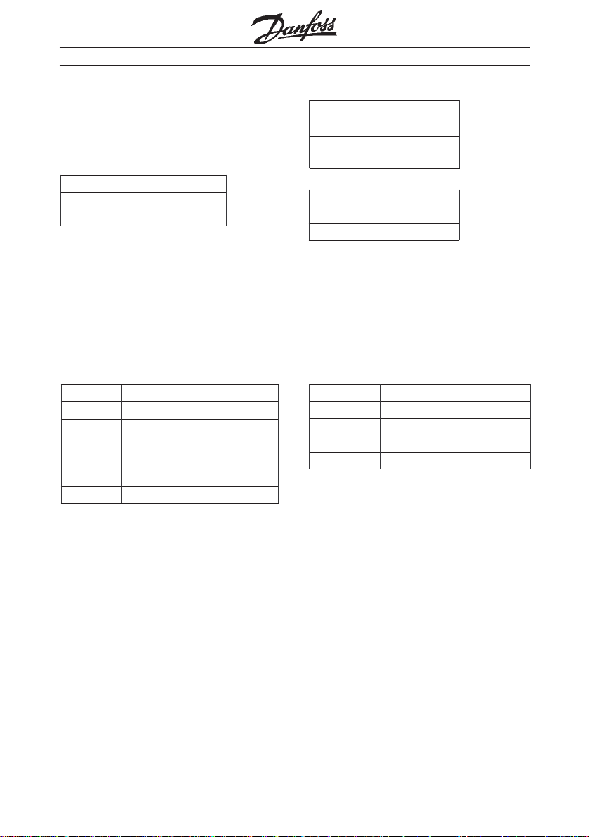
Parameterization
Parameterization via the Bus is only
possible if using PPO Type1.
Parameterization is ef fected via PCP
Communication. The procedure i s a s
follows:
Order to Report from
IBS-master: VL T
W rite.Request Confirmation
Read.Request Confirmation
®
to master:
positive
Confirmation
negative, r eporting
of er ror code
positive includes
the data of the
r equested parameter of the VLT
Confirmation
negative, r eporting
of er ror code
P roperties of PROFIBUS-DP
English Deutsch
®
MG.10.G1.51 – VLT i s a r egister ed Danfoss trademark
5
Page 6

■
Parameter interface in
W rite.Request
The parameter interface (PCV) of the VLT
5000 contains a total of 4 words. This
enables r eading and writing of paramet e r s, reading of arrays, writing, etc.
The parameter interface can be detailed
as follows:
1. Word (Parameter -Identification-Value,
PCA); in the lower 11 bits (bits 0..10) enter
P roperties of PROFIBUS-DP
the parameter number, i n the upper four
bits (bits 12..15) select the desir ed action.
2. Word (Index/Subindex, IND); the byte
"Index" is only used if wanting to use
elements of an array. I n this case, enter
the index of the element in question. In
normal parameter actions, this byte is not
used. The byte subindex is intended for
subsequent extensions and is not used at
this point.
Gateway InterBus-S
Example:
®
5000, with bus address 2, the
In VLT
®
parameter 202 maximum frequency is to
be changed to 80 Hz,
PCA: 20CA
Parameter CA hex = 202
Action 2 = Change parameter value
IND: 0000
no Subindex
no Index
PVA: 0000 0320
Parameter value_low =
320 hex = 800 = 80.0 x Factor 10
Parameter value_high = 0
3. + 4. Wo rd (Parameter Value, PV A) ; i n
the case of write action, this is where the
value of the selected parameter is enter ed. The thir d word is the High-Wo r d; the
fourth word is the Low-Wor d. The thir d
wor d is only used if parameter values
above 65535 are to b e transmitted.
Since values are not transmitted in
comma format, each parameter value
must be multiplied by a factor. The parameter factor in each case can be seen
from the manual for the PROFIBUS Option
Card .
6
MG.10.G1.51 – VLT is a r egister ed Danfoss trademark
Page 7
The r equest on the PCP channel now
looks as follows:
All values in hex.
W rite.Request
No. of subsequent values
invoke_id Communications
Reference
index
VLT®-Address No. of Bytes
PCA
IND
High_Parameter value
Low_Parameter value
Successful completion is indicated in the
form of a positive confirmation.
I f al l VLTs a re to be parameterized at the
same time, a zero i s to be enter ed instead
of the VLT-address.
■
Parameter interface in
Read.Request
Responses from the VLT® to an or der
initiated pr eviosly via Write.Request. Data
is only available in the case of a positive
confirmation; if ther e is a negative
confirmation, an err or code is r eported.
1. Word (Parameter-Identification-Value,
PCA); in the lower 11 bits (bits 0..10) the
®
enters the parameter number; in the
VLT
upper four bits (bits 12..15) the type of
r esponse appears.
Gateway InterBus-S
8082
007
00 02
5FA5
02 08
20CA
0000
0000
0320
Now the length of the data has to be
enter ed; since, however, this is only pr epared for the maximum layout, a length of
112 bytes has to be entered here. Now
follows the data of the VLTs, i n the sequence of their addresses.
3. + 4. Wo r d (Parameter value, PVA) ; this
is wher e the VLT
selected parameter. The thir d wor d is the
High-Wor d; the fourth word is the LowWor d. The thir d wor d is only used if parameter values above 65535 have been
transmitted.
Since the values to be transmitted are not
transmitted in comma format, the individual parameter value must be divided by a
factor to obtain the actual value. The individual parameter factor can be seen in the
manual for the PROFIBUS Option Card.
®
enters the value of the
P roperties of PROFIBUS-DP
English Deutsch
2. Word (Index/Subindex, IND); the byte
"Index" is only enter ed if elements of an
array have been accessed. In normal parameter actions, this byte is not used. The
byte subindex is intended for subsequent
extensions and is not used at this point.
MG.10.G1.51 – VLT i s a r egister ed Danfoss trademark
7
Page 8
Gateway InterBus-S
Example:
®
The r esponse fr om the VLT
5000 is to be
r ead onto the above order transmitted via
W rite.Request.
The order on the PCP Channel looks as
follows:
All values in hex.
Read.Request
P roperties of PROFIBUS-DP
No. of subsequent values
invoke_id Communications
Refer ence
index
VLT-Addr ess No. of Bytes
After completion of the Read.Request, the
following data is obtained:
PC V: 10CA
Parameter CA hex = 202
Action 1 = Transmission of
parameter value
IND: 0000
no Subindex
no Index
8081
0003
00 02
5FA5
02 00
PVA: 0000 0320
8
Parameter value_low =
320 hex = 800 =
80.0 x Factor 10
Parameter value_high = 0
MG.10.G1.51 – VLT is a r egister ed Danfoss trademark
Page 9
■
Properties of InterBus-S
■
ID-Code
The ID-Code of the Gateway : F1hex 241dec
32 wor ds, of which:
Bus width 4 to 32 wor ds
- 4 w ords PCP
- 0 - 28 words process data channel
(2 w ords per VLT
■
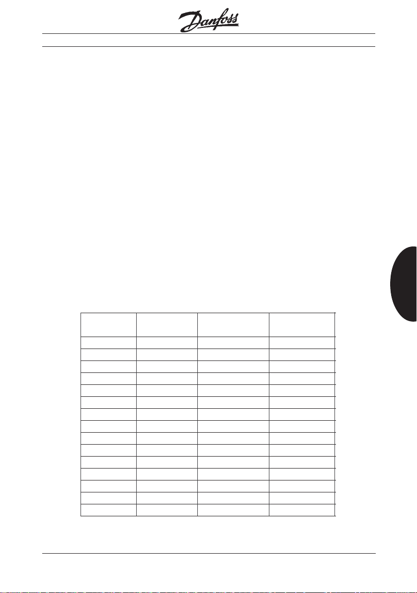
Length codes
Since all r egister widths ar e not possible in
InterBus-S, fill wor ds have to be enter ed in
some configurations of the gateway.
Furthermor e, not all InterBus-S-Masters
a r e able to serve a 4-wor d-wide PCP
Channel (Firmware versions befor e 4.0).
No. of InterBus-S Length code Length code
VLT® 5000 Bus width 1 word PCP 4 words PCP
®
) In- / Output
0 4 03 hex 00 hex
1 6 05 hex 02 hex
2 8 07 hex 04 hex
3 10 09 hex 06 hex
4 12 0B hex 08 hex
5 14 0D hex 0 A hex
6 16 0F hex 0C hex
7 24 17 hex 14 hex
8 24 17 hex 14 hex
9 24 17 hex 14 hex
10 24 17 hex 14 hex
11 32 1F hex 1C hex
12 32 1F hex 1C hex
13 32 1F hex 1C hex
14 32 1F hex 1C hex
Gateway InterBus-S
In this case another 3 words have to be
considered by the PCP Channel when
calculating the length code. The relevant
length codes for your configuration can be
seen fr om the following table:
Properties of InterBus-S
English Deutsch
MG.10.G1.51 – VLT i s a r egister ed Danfoss trademark
9
Page 10
Gateway InterBus-S
■
PCP Communication
■
Communication objects
Number of VLT® 5000
Index: 5F A0 hex
Symbol: inv_count
Data type: Unsigned8
Properties of InterBus-S
This enables reading of the number of
fr equency converters expected on the
PROFIBUS side as set at the rotary
switch. This is not necessarily the number
o f f requency converters actually
connected.
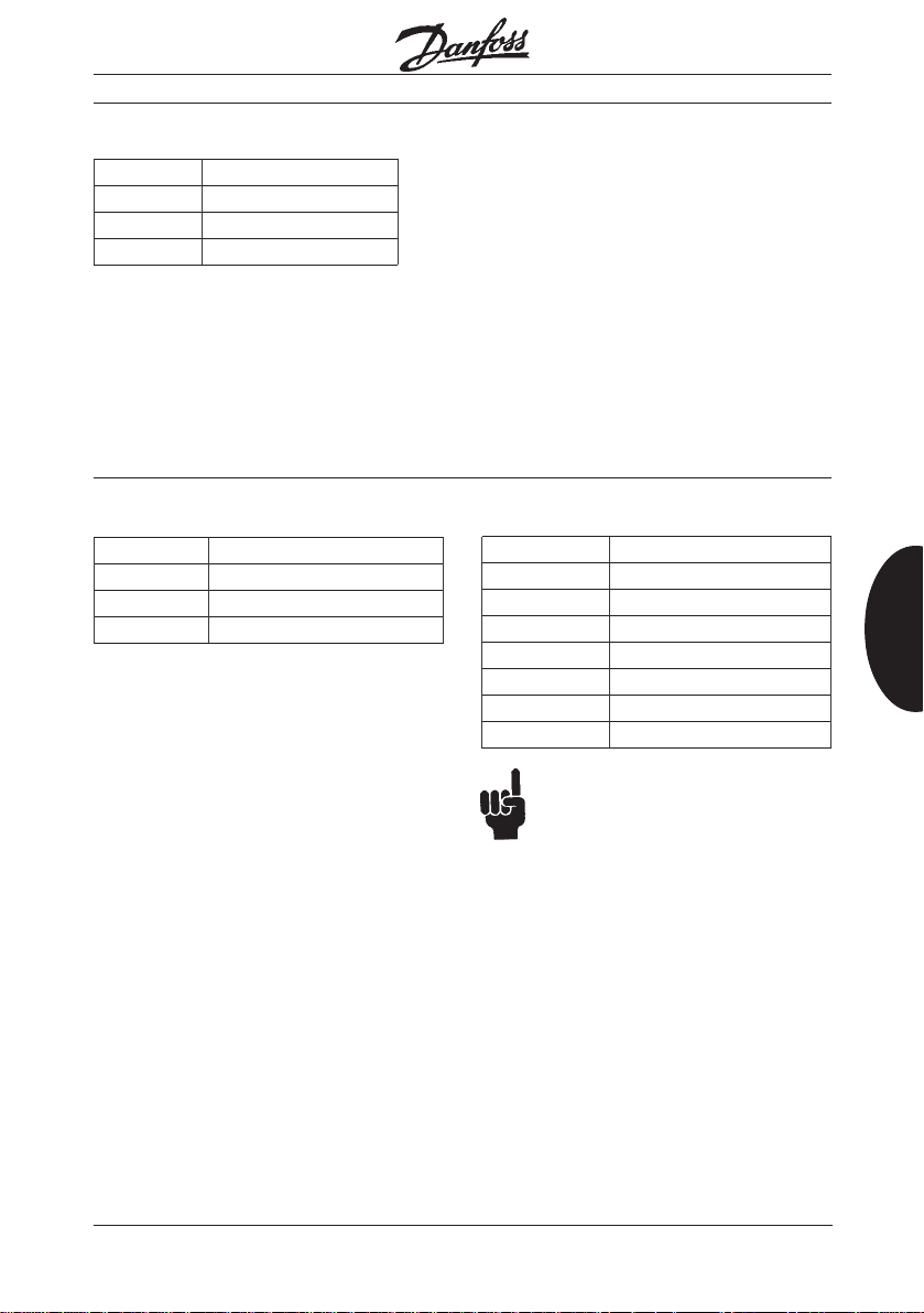
State of the fr equency converter
Index: 5FA2 hex
Symbol: inv_state
Data type: Subindex1: Unsigned
8
Subindex2: Unsigned
8
Access: Read only
®
I f al l VLT
tr oublefr ee at the bus, the two subindices
come out as zer o. I f t h ere is a disturbance of communication, subindex1 gives
the lowest address at which a communication err or occurred, while subindex2
p rovides more detailed information about
the err or in question.
set at the r otary switch work
Selected PPO Type
Index: 5FA1 hex
Symbol: ppo_type
Data type: Unsigned8
Access: Read only
PPO T ype ppo_type
PPO1 0 1 he x
PPO3 0 3 he x
This enables r eading of the PPO Type set
at the slide switch.
inv_state.2 E rror type
01 hex VLT® not found
®
02 hex VLT
not in Data
exchange
03 hex Master not active
10
MG.10.G1.51 – VLT is a r egister ed Danfoss trademark
Page 11
InterBus-S Module err o r
Index: 5FA3 hex
Symbol: stat_err
Data type: Boolean
Access: Read/Write
If an InterBus-S-Slave detects an error,
the slave can r eport the err or to the
InterBus-S-Master. The master then
rejects the latest data cycle and begins an
identification cycle, by which the master
pinpoints the participant that r eported the
module erro r.
Baudrate on the PROFIBUS-DP
Gateway InterBus-S
Using stat_err, it is possible to select
whether, an error on the PROFIBUS-DPside is to trigger a module err or.
stat_err = FF hex module erro r i s
trigger e d
stat_err = 00 hex module error i s not
trigger e d
The pre-set value is FF hex, i.e. module
e r r or is activated as err or r eport.
Properties of InterBus-S
Index: 5FA4 hex
Symbol: baud_rate
Data type: Unsigned8
Access: Read/Write
This enables reading and setting of the
baudrate at which work is carried out on
the PROFIBUS-side. In order to change
the baudrate, the PROFIBUS must be
stopped completely and initialized with
the new transmission speed.
baud_rate Baudrate
00 hex 9.600 Bit/s
01 hex 19.200 Bit/s
02 hex 93.750 Bit/s
03 hex 187.500 Bit/s
04 hex 500.000 Bit/s
05 hex 750.000 Bit/s
06 hex 1.500.000 Bit/s
At pr esent it is not possible to set
the baudrate. The baudrate has
been pr e-set permanently to
1.5MBaud and the object can only
be r ead.
English Deutsch
MG.10.G1.51 – VLT i s a r egister ed Danfoss trademark
11
Page 12

Gateway InterBus-S
P C V -part of PPO1
Index: 5FA5 hex
Symbol: PC V
Data type: 1 4 OCTET_STRING
with 8 Octets each
Access: Read/Write
This object services the purpose of
reading and writing the first 8 Octets
(PCV-part) of PPO Type1. The 14
Properties of InterBus-S
elements of object 5FA5 hex can be read
and written individually or jointly.
In o r der to r ead or write the PCV-part of a
®
connected VLT
, the number of the VLT
is transmitted as a subindex in addition to
the index in connection with
W rite.Request. See example on page 6.
W rite access:
Attempts at writing only r eceive a positive
confirmation handshake if the new value
enter ed can in fact be entered for the
frequency converter in question, i.e. if :
1 . PPO Type1 is used,
2 . the PROFIBUS-DP-Master is in
Operate mode
3.all frequency converters expected at
PROFIBUS-DP are in data exchange
mode.
4. New data has been sent to and re ceived by the PROFIBUS-DP at least
®
once.
Read access:
I n o r der to r etur n the r esponse values of
the VLTs, the structur e must be r ead.
The data is interpr eted as a parameter and
combined with the corresponding value of
the pr ocess data channel to form a telegram. A validity test is not carried
out.
Access to the two PPO objects is only
possible in accor dance with the switch
setting on the fr ont panel, i.e. if the switch
has been set to PPO Type3, the PPO
Type1 object cannot be r ead or written.
12
MG.10.G1.51 – VLT is a r egister ed Danfoss trademark
Page 13
■
Communication reference list
The following changes are requir ed to the
CRL (Communication re fe rence list). This
can be done via the PLC or via the PC
p rogram SYSSWT. The pr ocedur e for a
Siemens-PLC can be seen from the program example.
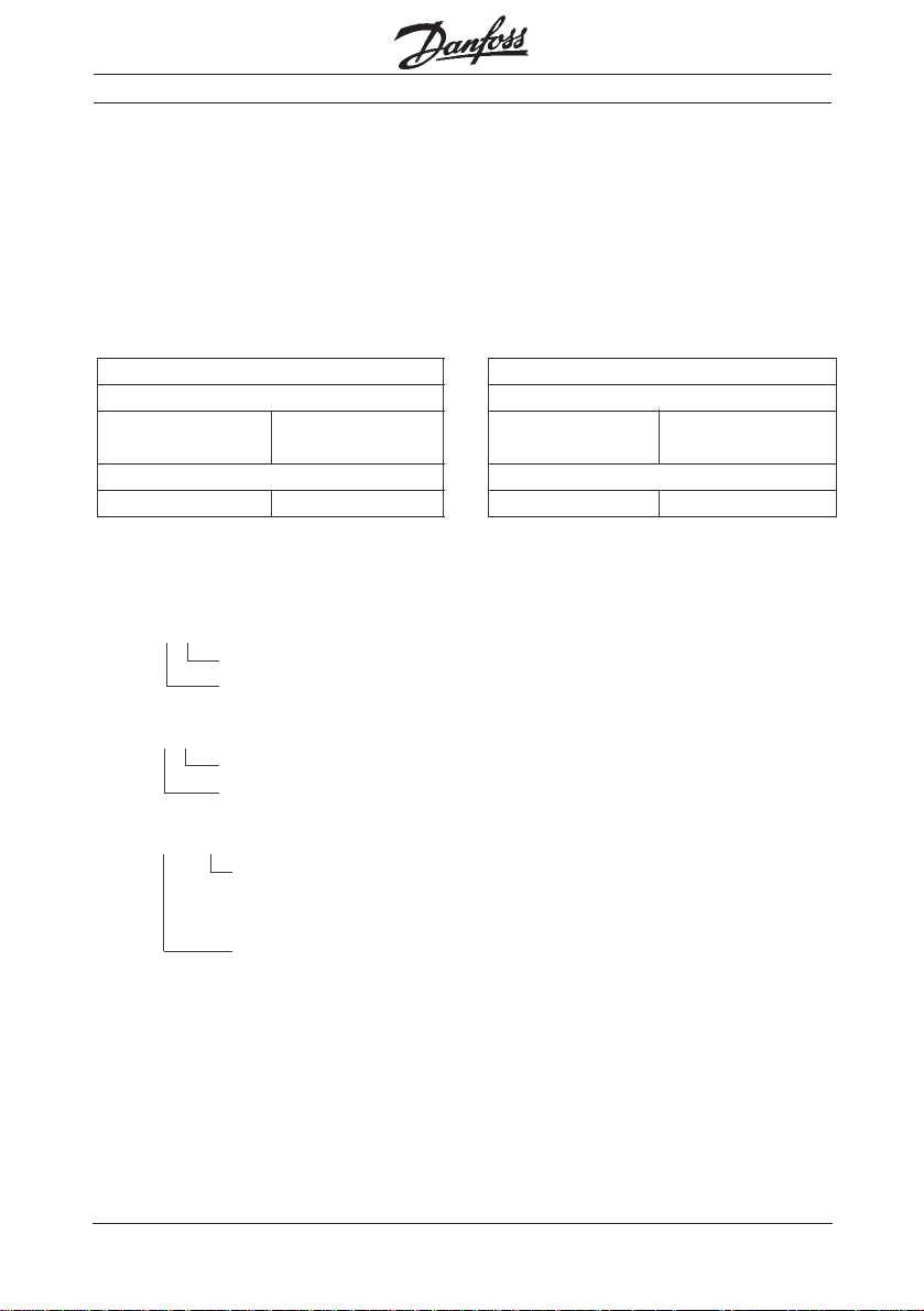
Maximum PDU length:
high prior r equests / r esponses: 00 hex
low prior r equests / r esponses: 80 h ex
high prior indications /
confirmations: 00 hex
low prior indications /
confirmations: 80 hex
■
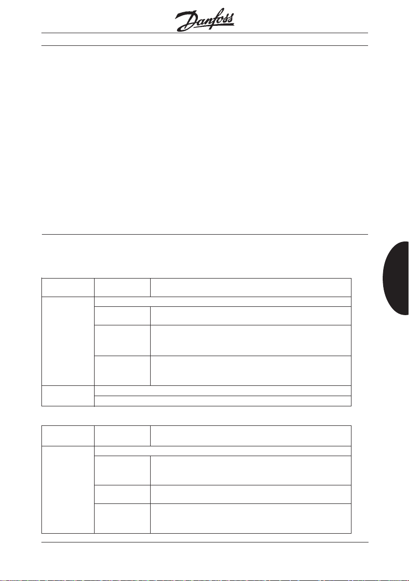
Error reporting in PCP
Communication
Err or_Class _"Access“ (06 hex):
E rror Code Additional Description
Error Code
05 hex object-attribute-inconsistent
10 hex bad-subindex
The transmitted subindex does not match the object in use
12 hex too-much-data
Mor e data bytes wer e transmitted than can be used for writing
the object
13 hex too-few-data
Fewer data bytes wer e transmitted than were required for writing
the object
08 hex type-conflict
An attempt was made to give a variable a value outside its value range
Gateway InterBus-S
supported services:
r equest / r esponses: 80 hex; 30 hex;
00 hex
indication / confirmation: 00 hex; 00 hex;
00 hex
In server operation the following services
a re supported:
get_OV_long
read_variables
write_variables
Properties of InterBus-S
English Deutsch
E r r or_Class _Access“ (08 hex):
E rror Code Additional Description
Error Code
00 hex other
1 hex not-pr ojected
The transmitted subindex in object PCV was bigger than the
p r e-set VLT
2 hex not-existent
In write access in object PCV at least one VLT
9 hex bad-data-value
The transmitted data value does not match the object intended
for use
MG.10.G1.51 – VLT i s a r egister ed Danfoss trademark
®
number
®
was not found
13
Page 14
Gateway InterBus-S
■
Technical data
Supply voltage: 24 V-DC ±1 0 % 240 mA
Oscillation test [ g ] 0,7
Relative humidity [%] VDE 0160 5.2.1.2.
Ambient temperatur e (as in VDE 0160) [° C ]0 → +60
Technical data
EMC Standards applied Emission EN 50081-2, EN 55011
Immunity EN 50082-2, IEC 1000-4-2,
IEC 1000-4-3, IEC 1000-4-4,
ENV 50140
ENV 50141
■
Examples of connection
14
MG.10.G1.51 – VLT is a r egister ed Danfoss trademark
Page 15
■
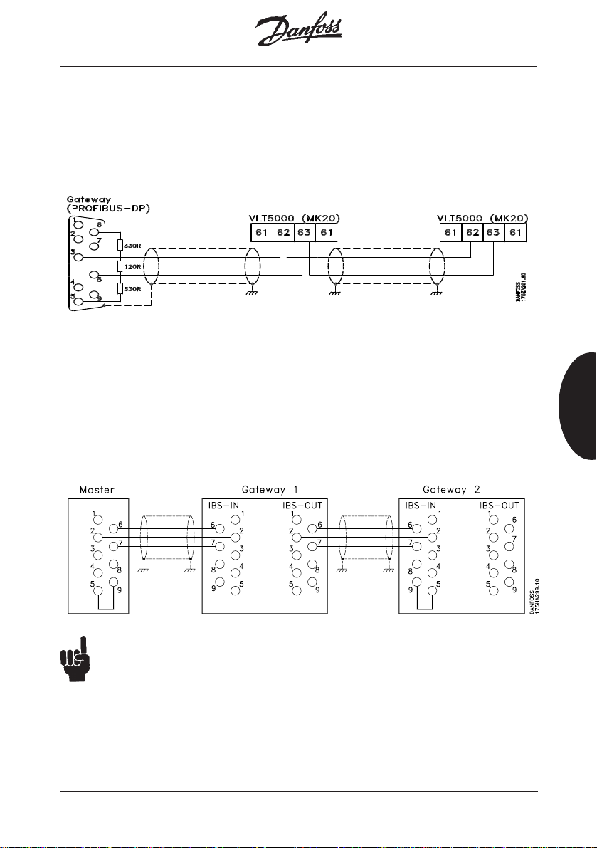
Connection of the PROFIBUS
bus wire
On the last VLT® the bus terminating r esistor must be activated; for this purpose,
switches S1 on the PROFIBUS Option
Card is to be switched into the ON position.
Note:
The cable screen must be connected to
the VLT enclosure by means of the clamp
placed beside the control c ard a t the left
side of the VLT.
■
Connection of the Interbus-S
bus wire
Gateway InterBus-S
At the Gateway the cable screen must be
connected to the housing of the Sub-D
connectors by means of the clamp inside
the connector.
Technical data
English Deutsch
Pins 5 and 9 must be bridged
in the IBS IN plug, if nothing is
connected to the IBS OUT plug.
(See above regarding connection of the cable screen).
MG.10.G1.51 – VLT i s a r egister ed Danfoss trademark
15
Page 16
Gateway InterBus-S
■
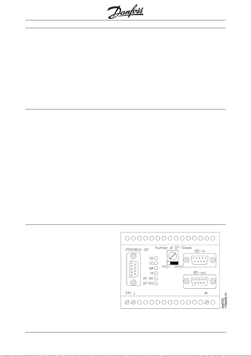
Display messages
Ub
all voltages ar e ok
BA
InterBus-S active, Master is connected
Technical data
and active
CC
InterBus-S is ok, data exchange is
occurring
■
Operating elements
Number of DP-Slaves
Hex-r otary switch for the number of
connected VLTs, setting > 14 leads to a
flashing LED "DP ok"
PPO1 / PPO3
Slide switches for the selection of PPO
Type1 or PPO Type3, all VLT
be set to the same PPO Type.
The positions of these two switches are
adopted at Power-Up. If these ar e
displaced during operation, the LED
"DP ok" flashes
®
3000 must
TR
PCP transmission is in progr ess
DP ok
PROFIBUS-DP is ok, all participants
selected on the rotary switch communicate
DP TXO
the gateway is transmitting via the
PROFIBUS-DP
■
Terminals and plugs
3 terminals:
Voltage supply 24 V-DC (+ ; -);
Earth
1 SUB-D-female plug 9 pol.:
PROFIBUS-DP-connection
1 SUB-D-male plug 9 pol.:
InterBus-S IN
1 SUB-D-female plug 9 pol.:
InterBus-S-OUT
■
Housing
Enclosur e IP20
Terminal rail housing LDG-A30
Dimensions: 112x100x75 (HxLxW)
16
MG.10.G1.51 – VLT is a r egister ed Danfoss trademark
Page 17

■
Example of program for Siemens
S5-115U
The following example shows how the
communication to a VLT
to the gateway is controlled.
®
5000 connected
Gateway InterBus-S
■
P rogram references
DB21
is the Communication-Request-DB; this is
where the or ders for the PCP Communication ar e supported
Example of program for Siemens S5-115U
®
Also, in this example, the VLT
is parame-
terized by way of PCP Communication.
Example layout
■
S5-115U with an Interbus-S-Master
module, IBS/DP-gateway with a VLT
5000 that has a PROFIBUS Option Card.
Setting of the Interbus-S-Master
■
Selection of start Operating mode
and operating controlled
mode: DCB-Mode
W indow 1: Basic address =
P-range upwards of 32
Length = 64 Bytes
W indow 2: Basic address =
P-range upwards of 128
Length = 32 Bytes
W indow 3: Basic address =
P-range upwards of 200
■
Required FBs
(Function Blocks)
For communication via PCP, the following
FCs are r equired - and can be obtained
from Phoenix:
FB 60 INITIB
F B 62 CON/IND
FB 63 CIH
F B 6 6 REQ/RES
FB 68 CONTROL
FB 69 DEFINE
F B 72 ADDRESS
DB23
is the Communication-Confirmation-DB;
this is wher e the PCP Communication
enters the r esponses
®
FW 20
is the activation wor d for PCP Communication
FW 22
is the r eporting wor d for PCP Communication
English Deutsch
F 224.1
activates the Download.
®
The Contr ol word for the VLT
is located
i n QW38, the Desired value in QW40
®
The Status word of the VLT
is located in
IW38, the Actual value in IW40
Starting the VLT
■
®
The VLT® starts when the lower Bit-7 in
QB39 has been set. Stopping can be
achieved by zeroing of this bit. In this
context, ther e is a choice of motor
coasting, quick-stop and normal stop.
MG.10.G1.51 – VLT i s a r egister ed Danfoss trademark
17
Page 18

■
Setting the PDU length in PCP
On the basis of the possibility of having 14
VLTs connected to the gateway, t h e re is a
need for an extended PDU length. The
following example shows how in the SPS
start-up the PDU length can be changed
in CRL. For further information concer ning
the PCP Communication please see the
manual for the InterBus-S-Master.
All start-up components first branch into
FB210, which carries out the configuration of the InterBus-S-Master assembly.
Example of program for Siemens S5-115U
Gateway InterBus-S
18
MG.10.G1.51 – VLT is a r egister ed Danfoss trademark
Page 19

Gateway InterBus-S
OB 20
:JU F B 210 ;Initialization of the IBS-module
NAME :ANLAUF
:BE
OB 21
:JU F B 210 ;Initialization of the IBS-module
NAME :ANLAUF
:BE
OB 22
:JU F B 210 ;Initialization of the IBS-module
NAME :ANLAUF
:BE
OB1
: JU FB 62
NAME :CON/IND
IBDB : DB 9 InterBus Data block
CIDB : FY 18 CON/IND caption table
T : T 1 T imer
T O : F 8.3 Time Out
: L KB 1
:T FY 201
:O F 0.0
: O N F 0.0
:= F 0.1
:
:A F 224.1 Activation for Download
: A F 200.5 Activation for FB1
:JC FB 1 Parameterization VLT1
NAME:VLT-PARA
STRC : F 200.0 Auxiliary flag
STR1 : F 200.1 Auxiliary flag
STR2 : F 200.2 Auxiliary flag
R D B : DB 23 Request-DB
C D B : D B 21 Confirmation-DB
VLT : FY 201 VLT Addres s
AKTI : F 21.0 Activation for PCP Communication
PKEW : F W 210 PCA to the VLT
PA RW : F W 212 Parameter value to the VLT
Example of program for Siemens S5-115U
English Deutsch
MG.10.G1.51 – VLT i s a r egister ed Danfoss trademark
19
Page 20

PKER : F W 214 PCA from the VLT
PA R R : F W 216 Parameter value from the VLT
PCPR : F 200.3
E R R : F 200.6
O K : F 200.7
:
:O F 200.6 ;If error, r everse activation
:R F 200.5
:
: A F 200.7 ;OK-report fr o m FB 1
:A F 224.1 ;Activation for Download
:JC F B 2
NAME:PARAMETE
P D B : D B 100 DB with Download data
COUN: F W 220 Parameter counter
Example of program for Siemens S5-115U
ANZA : KF +17 Number of parameters
PKEW: F W 210 PCA to the VLT
PA R W : F W 212 Parameter value to the VLT
O K : F 200.7 OK-report fr o m F B1
STRT : F 200.5 Start for FB1
ZEIG : F W 222 Parameter indicator
INIT : F 224.0 Download initialized
:
: JU FB 66
NAME:REQ/RES
IBDB : D B 9 InterBus Data block
RRDB : FY 19 REQ/RES caption table
T : T 3 Timer
T O : F 8.4 Time Out
:BE
Gateway InterBus-S
FB 210
NAME:ANLAUF
:A F 8.0
:ON F 8.0
:S F 8.0 Activation bit: INITIB
:S F 10.0 ADDRESS
:L K Y 20,22 CON/IND,REQ/RES
:T F W 18 DB PCP caption tables
M002 :A F 8.0
:JC FB 60
NAME:ANLAUF
IBDB : D B 9 InterBus Data block
20
MG.10.G1.51 – VLT is a r egister ed Danfoss trademark
Page 21

Gateway InterBus-S
FEN3 : KF +200 Basic address: Window 3
AV : KF +1 Controlled operation / r eport r eleased
RRST : D B 23 REQ/RES Standard DB
CIST : DB 21 CON/IND Standard DB
RRMW: KF +20 Activation wor d
CIMW: K F + 22 Report word
CIFB : FY 63 Auxiliary driver CON/IND
T : T 0 Timer
STEP : FY 9 Inter nal flag byte
BUSY : F 8.0 Activation bit
T O : F 8.1 Time Out
R E T : F 8.2 Return value
: A F 8.0
:ON F 8.2
:JC =M001
:STS
:BEU
M001 :JU FB 62
NAME:CON/IND
IBDB : D B 9 InterBus Data block
CIDB : FY 1 8 Caption-DB-CON/IND
T : T 1 Timer
T O : F 8.3 Time Out
Example of program for Siemens S5-115U
English Deutsch
: **** Change PDU length ********
: change in CRL, here o nl y !! !
:LKF+8
:T F Y 100 Function 8
: L KF +25
:T FY 101 DB-Number is 25
:LKF+0
:T FY 102 upwards o f D W 1
: AN F 8.0 No BUSY-Signal fr o m FB60
:A F 10.0 Pseudo-cycle
:JC FB 69 DEFINE from IBS
NAME:DEFINE
IBDB : D B 9 InterBus DB
T : T 5 Timer No.5
FKT : FY 100 Function (8) Receive CRL
D B : FY 101 DB-Number
D W : FY 102 upwards of D W
BUSY : F 103.0
T O : F 103.1
MG.10.G1.51 – VLT i s a r egister ed Danfoss trademark
21
Page 22

RET : F 103.2
:
:AN F 103.0 No BUSY from DEFINE FB69
:AN F 8 . 0 No BUSY from FB60
:A F 10.0 Pseudo-cycle
:JC F B 72
NAME :ADDRESS
IBDB : D B 9 InterBus Data block
BUSY : F 10.0 Activation bit
T : T 2 T imer
IDDB : D B 10 DB: ID-Code list
IDDW : KF +0 D W:
LBDB : D B 11 DB: Bus segment list
LBDW : KF +0 D W:
INDB : D B 12 DB: IN-Addre s s l i st
Example of program for Siemens S5-115U
INDW : KF +0 D W:
OUDB : D B 13 DB: OUT -Address List
OUDW: KF +0 D W:
KRDB : D B 14 DB: KR-Address List
KRDW: KF +0 D W:
GRDB : D B 0 DB: Group definitions
GRDW: KF +0 DW:
MODE: F 10.5 Mode of indication
EREG : FY 12 Error Register
T O : F 10.1 Time Out
R E T : F 10.2 Retur n value
:
:JU F B 66
NAME :REQ/RES
IBDB : D B 9 InterBus Data block
RRDB : FY 19 Caption-DB-REQ/RES
T : T 3 T imer
T O : F 8. 4 Time Out
: A F 8.0 INITIB
:O F 10.0 ADDRESS
:JC =M002
:AN F 10.2
:BEB
:STS
:BE
Gateway InterBus-S
22
MG.10.G1.51 – VLT is a r egister ed Danfoss trademark
Page 23

Gateway InterBus-S
FB1
NAME:VLT-PARA ;Parameterization via IBS/DP
DECL :STRC IBI
DECL :STR1 IBI
DECL :STR2 IBI
DECL :RDB B
DECL :CDB B
DECL :VLT IBY
DECL :AKTI I B I
DECL :PKEW IW
DECL :PA RW IW
DECL :PKER Q W
DECL :PARR Q W
DECL :PCPR IBI
DECL :ERR IBI
DECL :OK IBI
Example of program for Siemens S5-115U
:AN =STRC Initiate Request alr eady sent?
:JC =INIT NO-> Inititate Request
: A =STR1 Ctrl1=1 AND Ctrl2=0
:AN =STR2 -> wait for W rite_Conf
:JC =WCON
:AN =STR1 Ctrl1=0 AND Ctrl2=1
: A =STR2 -> wait for Read_Conf
:JC =RCON
:DO =RDB
:L KH 8082 Identification Write_Request
: T DW 0
:L KH 0007 ParameterCounter = 7
:T DW 1
:L KH 0002 CR=2
:T DW 2
:L KH 5FA5 P C V-Object
:T DW 3
:L =VLT VLT-Address is Subindex
: T DL 4
:L KB 8 No. of bytes = 8
: T DR 4
:L =PKEW retrieve or der for VLT
: T DW 5
:L =PARW retrieve Para-value for VLT
: T DW 8
:A F 0 .1 VKE"1"
English Deutsch
MG.10.G1.51 – VLT i s a r egister ed Danfoss trademark
23
Page 24

:S =STR1 W rite_Request executed
:JU =CON0 Delete conf and send order
:
WCON : **** Wait for W rite_Confirm.
:DO =CDB Open confirmation DB
:L D W 0 Retrieve conf_identification
:L KH 0000
:!=F ;is 0 then wait again
:BEB
:L DL 3 retrieve Result
:><F is not ZERO
: JC =FAUL - > FAULT
:
READ : *** execute READ-REQUEST ****
:DO =RDB Open Request DB
Example of program for Siemens S5-115U
:L KH 8081 O rder identification Read_Request
: T DW 0
:L KH 0003 Parametercounter = 3
: T DW 1
:L KB 0
:T DR 4 No. of bytes = 0
: CR; Object and VLT remain
:A F 0.1 VKE"1"
: R B =STR1 STR1=0 AND STR2=1
:S =STR2 - > wait for Read_confirmation
:JU =CON0 Delete conf and send order
:
RCON: *** wait for READ-Confirmation
:DO =CDB Open confirmation DB
:L D W 0 Retrieve confirmation identification
: L KH 0000
:!=F is 0 then wait again
:BEB
:L DL 3 Retrieve Result-Code
:><F i s not 0
: JC =FAUL - > FAULT
:L D W 4 Retrieve PCA received
:S LW 5 only Para-number
:L =PKEW Retrieve Para-number sent
:S LW 5 Only Para-number
:!=F equal then OK
:JC = O K Enter value
:JU =READ if NOT ZERO, then READ again
Gateway InterBus-S
24
MG.10.G1.51 – VLT is a r egister ed Danfoss trademark
Page 25

Gateway InterBus-S
OK :
:L DW 4
:T =PKER
:L DW 7 Retrieve parameter value r eceived
:T =PARR
:A F 0. 1 VKE"1"
: S = O K Set OK-flag
:RB =STR1
:RB =STR2
:BEU
INIT : *** INITIA T E REQUEST ***
:A =STR1 is not first run
:JC =INI1
:DO =RDB Open Request component
:L KH 808B Order identification Inititate Request
: T DW 0
:L KH 0002 PC and CR
:T DW 1 Parameter Counter
:T DW 2 Invoke ID / CommRef
:L KY 0,0
:T DW 3 Control word, Access Group
: A F 0. 1 VKE"1"
: S =STR1
CON0: *** Delete confirmation ***
:DO =CDB Search Confirmation module
:L KH 0000 Delete entries
: T DW 0
:T DW 1
:T DW 2
:T DW 3
:T DW 4
:T DW 5
:A F 0 .1 VKE"1"
: S =AKTI Set activation marker
:BEU
INI1 **** W ait for Response ****
:B =CDB Confirmation DB on
:L D W 0 Fetch confirmation identification
: L KH 0000
:!=F is equal to 0-> no Confirmation
:BEC then continue searching
: L DL 3 Retrieve quitting code
: L KH 0000
Example of program for Siemens S5-115U
English Deutsch
MG.10.G1.51 – VLT i s a r egister ed Danfoss trademark
25
Page 26

Gateway InterBus-S
:!=F is 0 -> no fault
:JC =INI2
FAUL : **** F A U LTS ****
:A F 0.1 VKE"1"
: S =ERR Fault occurr ed
:RB =STRC Reset first run
:RB =STR1
:RB =STR2
:BEU
INI2 : *** Initiate Request OK ***
:A F 0.1 VKE"1"
: S =STRC Set Inititate successful
:RB =STR1 Reset flag
:BE
Example of program for Siemens S5-115U
FB2
NAME:PARAMETER
DECL :PDB B
DECL :COUN IW
DECL :ANZA DKF
DECL :PKEW IW
DECL :PA RW IW
DECL :OK IBI
DECL :STRT IBI
DECL :ZEIG IW
DECL :INIT IBI
:
:DO =PDB Open data-DB
:AN =INIT
:JC =INIT
STRT :
:LW =ANZA retrieve number
:L =COUN retrieve pr esent number
:>F not end yet
: J C =WEIT - > continue
:RB = O K FINISHED
:RB =INIT Reverse INIT
: R F 224.1
:BEU and END
26
MG.10.G1.51 – VLT is a r egister ed Danfoss trademark
Page 27

Gateway InterBus-S
WEIT :L =ZEIG Retrieve indicator
: T FW 250
:DO FW 250
:L D W 0 Retrieve DW from indicator address
: L KH 2000
:+F +2000, for write identification
: T =PKEW is new PKEW
:L =ZEIG
:I1
:T FW 250
:DO FW 250
:L D W 0 load DW to indicator address
: T = PA R W is new parameter value
: L =ZEIG
:L KF +2
:+F
: T =ZEIG
:L =COUN
:I1
:T =COUN Counter + 1
:RB = O K OK for FB1 reset
: S =STRT and FB1 start anew
:BEU
INIT :L KH 0000
:T =ZEIG
:T =COUN
:S =INIT
:JU =STRT
:BE
Example of program for Siemens S5-115U
English Deutsch
DB9
0 : KH 0000;
1 : KH 0000;
254 : KH 0000;
255 : KH 0000;
DB10 ;Ident-code list
0 : KY 0,3 ;Number of parameters
1: KY 5,241 ;IBS-PB Gateway
2: KY 0,16 ;Diagnose Bit Register
3 : KY 0,17 ;Diagnose Parameter Register
4: KY 0,0 ;Length code 1Unit PPO1=5
5: KY 0,0 ;" 6UnitsPPO1=15
MG.10.G1.51 – VLT i s a r egister ed Danfoss trademark
27
Page 28

DB11 ;Bus segment list
0: KY 0,3 ;Number of parameters
1: KY 0 ,0 ;IBS<>PB Gateway
2: KY 0,0 ;Diagnose Bit Register
3 : KY 0,0 ;Diagnose Parameter Register
DB12 ;IN address list
0: KY 0,3 ;Number of parameters
1: KY 0,32 ;IBS<>PB Gateway
2: KY 0,126 ;Diagnose Bit Register
3 : KY 0,128 ;Diagnose Parameter Register
DB13 ;OUT address list
0: KY 0,3 ;Number of parameters
1: KY 0,32 ;IBS-PB Gateway
Example of program for Siemens S5-115U
2: KY 0,0 ;Diagnose Bit Register
3 : KY 0,0 ;Diagnose Parameter Register
DB14 ;KR list
0: KY 0,3 ;Number of parameters
1: KY 0 ,2 ;IBS<>PB Gateway
2: KY 0,0 ;Diagnose Bit Register
3 : KY 0,0 ;Diagnose Parameter Register
Gateway InterBus-S
DB20 ;CON/IND caption table
0: KH 0000 ;1. CODE;
1: KH 0000 ; PC ;
2: KH 0000 ; KR ;
3: KY 0,0 ; DB,DW;
4: KH 0000 ;2. CODE;
5: KH 0000 ; PC ;
6: KH 0000 ; KR ;
7: KY 0,0 ; DB,DW;
8: KH 0000 ;3. CODE;
52 : KH 0000 ;14.CODE;
53 : KH 0000 ; PC ;
54 : KH 0000 ; KR ;
5 5 : KY 0,0 ; DB,DW;
56 : KH 0000 ;15.CODE;
57 : KH 0000 ; PC ;
58 : KH 0000 ; KR ;
5 9 : KY 0,0 ; DB,DW;
60 : KH 0000
28
MG.10.G1.51 – VLT is a r egister ed Danfoss trademark
Page 29

Gateway InterBus-S
DB21 ;CON/IND-Standard-DB
0: KH 0000 ;CODE ;
1: KH 0000 ; PC ;
2: KH 0000 ; KR ;
3 : KH 0000 ;Body ;
4 : KH 0000
30 : KH 0000
31 : KH 0000
32 : KH 0000
33 : KH 0000
34 : KH 0000
DB22 ;REQ/RES caption table
0: KH 0000 ;1. CODE;
1: KH 0000 ; PC ;
2: KH 0000 ; KR ;
3: KY 0,0 ; DB,DW;
4: KH 0000 ;2. CODE;
5: KH 0000 ; PC ;
6: KH 0000 ; KR ;
7: KY 0,0 ; DB,DW;
8: KH 0000 ;3. CODE;
Example of program for Siemens S5-115U
English Deutsch
52 : KH 0000 ;14.CODE;
53 : KH 0000 ; PC ;
54 : KH 0000 ; KR ;
5 5 : KY 0,0 ; DB,DW;
56 : KH 0000 ;15.CODE;
57 : KH 0000 ; PC ;
58 : KH 0000 ; KR ;
5 9 : KY 0,0 ; DB,DW;
60 : KH 0000
DB23 ;REQ/RES-Standard-DB
0: KH 808B ;CODE ;
1: KH 0002 ; PC ;
2: KH 0002 ; K R
3: KH 0000 ;Body ;
4 : KH 0000
MG.10.G1.51 – VLT i s a r egister ed Danfoss trademark
29
Page 30

58 : KH 0000
59 : KH 0000
60 : KH 0000
61 : KH 0000
62 : KH 0000
DB25 ;Setting of the PDU length
0: KH 0003 ;Length 3 words
1 : KH 0002 ; 0.entry CR=2
2 : KH 0A80 ;10.entry 80 hex
3 : KH 0C80 ;12.entry 80 hex
DB100 ;Download Data
0: KF +201 ;Parameter 201 Min.Frequency
1: KF +100 ;Value 100 = 10.0 Hz
Example of program for Siemens S5-115U
2 : KF +202 ;Parameter 202 Max.Frequency
3: KF +1000 ;Value 1000 = 100.0 Hz
4: KF +205
5: KF +1
6: KF +206
7: KF +2
8: KF +207
9: KF +3
1 0: KF +208
1 1 : KF +4
1 2: KF +209
1 3 : KF +30
1 4: KF +215
1 5: KF +111
1 6: KF +216
1 7: KF +222
1 8: KF +217
1 9: KF +333
2 0: KF +218
2 1: KF +444
2 2 : KF +0
2 3 : KF +0
2 4 : KF +0
Gateway InterBus-S
30
MG.10.G1.51 – VLT is a r egister ed Danfoss trademark
Page 31

2 5 : KF +1
2 6 : KF +0
2 7 : KF +2
2 8 : KF +0
2 9 : KF +3
3 0 : KF +0
3 1 : KF +4
3 2 : KF +0
3 3 : KF +5
Gateway InterBus-S
Example of program for Siemens S5-115U
English Deutsch
MG.10.G1.51 – VLT i s a r egister ed Danfoss trademark
31
Page 32

Page 33

A
Access to parameter change . .. .. .. ................4
B
Baudrate .. .. ... .. .. ....... .. .. ....... .. .. ....... .. .. ....... .. .4
Bus time out . . . . . . . . . . .. . . . . . . . . . . . .. . . . . . . . . . . . . .. . . . . . . . . .4
Bus time out function . . . . . . . . . . . . .. . . . . . . . .. . . . . . . . .. . . .4
C
Communication objects . . .. .. . .. .. . .. .. . .. .... . .. . ..10
Communication re f e rence list .....................13
Configuration of the fr equency converter .... .4
Connection of the Interbus-S wire . . . . . . . . . . . . . .15
Connection of the PROFIBUS bus wire . .. ...15
Control word . . . .. . . .. . . .. . ... . ... . . .. . ... . ... . . .. . ... . ... . . .5
D
Display messages . .. .. . .. .. . .. ........ .. .. . .. .. . .. .. . ..16
E
Error Code ..... ....... ........ ....... ........ ....... .......13
Error reporting in PCP Communication .. ... .13
Example of program for
Siemens S5-115U . ........ .. ........ .. ..... ... .. ..... .17
Example layout . . . .. . . . . .. . . . .. . . . . .. . . . .. . . . .. . . . . .. . . . .17
Example of connection . .. .. . .. . . .. . .. . . .. . .. . . .. . .. .14
F
FMS/DP-selection .. .. ..... ...............................4
Functional components . . .. . .. .... .. .. . .. . .. .. . .. . ..17
H
Housing . .. .. .. .. .. .. .. ...... .. .. .. .. .. .. .. .. .. .. .. .. .. .. .. ..16
I
ID-Code .. ..... .. .... ..... .. .... .. .... ..... .. .... .. .... .. .... ..9
Index/Subindex, IND . . . .. . . . .. . . . .. . . .. . . . .. . . . .. . . . .. . .6
InterBus-S Module erro r.............................11
Gateway InterBus-S
L
Length codes ............ .. .. ...................... .. .. ....9
M
Maximum PDU length ................................13
N
Notes concerning pr ogramming ..................5
Number of VLT® 5000 . .. .. ...........................10
O
Operating elements . .. . . .. . . .. . . .. . . . .. . . .. . . .. . . . .. . . .16
Overview .. .... .. .. . .. .. . .. .... .. .. . .. .. . .. .... .. .. . .. .. . .. ....2
P
Parameter 502-512 .... .. ...... .. ....... .. ....... .. .... 4
Parameter 800 . .. ........................ .. ................4
Parameter 801 . .. ........................ .. ................4
Parameter 803 . .. ........................ .. ................4
Parameter 804 . .. ........................ .. ................4
Parameter 904 .............................................4
Parameter 918 .............................................4
Parameter 927 .............................................4
Parameter 928 .............................................4
Parameter interface in Write.Request . . . . . . . . . . .6
Parameter interfaces in Read.Request .. . .. .. ..7
Parameter Value, PV . . . . .. . . . . . . . .. . . . . . . . .. . . .. . . . . . . . .6
Parameter-Identification-Value, PIV . .. .. . .. .. .. . .6
Parameterization . . . . . .. . . . . . . .. . . . . . . . .. . . . . . . . .. . . . . . . . ..5
PCP-Communication .................................10
P C V-part of PPO1 . . . . . .. . . . .. . . . . .. . . . .. . . . . .. . . . .. . . .12
PPO select . ... .. . .. .. .. . .. .. .. .. .. . .. .. .. .. .. . .. .. .. .. .. . .. ..4
PPO Types 1/PPO Types 3 . . . .. . . .. . . .. . . .. . . .. . . . 2
Pr ogram re f erences ..... .. .. .. ...... .. .. .. ...... .. .. ..17
Pr operties of InterBus-S . . . . .. . . . . .. . . . . .. . . . . .. . .. . . . .9
Properties of PROFIBUS-DP . .. .. .. .. .. .. .. .. .. .. .. .3
Index
English Deutsch
MG.10.G1.51 – VLT i s a r egister ed Danfoss trademark
33
Page 34

R
Read access . .... .... ..... .... .... ..... .... .... ..... .... ..12
Index
Read.Request .... .... ... ............... ................... .5
Refer ence/Actual values . . . .. . . . . . . .. . . . . . .. . . . . . . .. . .5
Reporting back . . . .. . . .. . . .. . . .. . . .. . . .. . . .. . . .. . . .. . . .. . . .2
S
Selected PPO Type ..... .... .... .... ... .... .... .... ... .10
Setting of the Interbus-S-Masters . . . . . . . . . . .. . .17
Setting the PDU length in PCP . .. . . . .. . . . .. . . . . ..18
Starting the VLT®. .. .. .. .. .. . . .. .. .. .. .. . . .. .. .. .. . . .. .. .17
State of the fr equency converter . .. ..... .. .. ....10
Station addr ess . . . . . . .. . .. . .. . .. . . .. . . . . . . .. . . . . . . .. . . . . . . .4
Supported services . . .. . . . .. . . . .. . . .. . . . .. . . .. . . . .. . . ..13
T
Technical data .. . .. . . . . .. . . . . .. . . . . .. . . . . .. .. . .. . .. . . . . .. .14
Terminals and plugs . . . . . . . . . . . . . . . . . . . . . . . . . . . . . . . . . . .16
W
W rite access . .. . .. . ... .. . .. .. . .. . .. . ... .. . .. .. . .. . .. . ... ..12
W rite.Request . . . .. . . . . .. . . . .. . .. . . . .. . .. . . . .. . .. . . . .. . .. . . .5
Gateway InterBus-S
34
MG.10.G1.51 – VLT is a r egister ed Danfoss trademark
Page 35

Gateway InterBus-S
Te i l 1 ■ Überblick . . .. . . . . .. . . . . .. . . . . . .. . . . . .. . . . . . .. . . . . .. . . . . .. . .. . . . . .. . . . . . .. . . . . .36
Te i l 2 ■ Eigenschaften der PROFIBUS-DP-Seite .... ........ ... .... ....37
Konfiguration des Frequenzumrichters . ...... .. ..... .. ..... .. ..... .. ..38
Anmerkungen für die Programmierung ...............................39
Steuerwort . .. .. .. .. . .. .. . .. .. . .. .. . .. .. . .. .. . .. .. . .. .. . .. .. . .. .. . .. .. . .. .. . .. .39
Soll- / Istwert ........ .................................................. .......39
Parametrierung .. ... .. .. .. .. .. . .. .. . .. .. .. .. .. . .. .. . .. .. .. .. .. . .. .. . .. .. .. .. .39
Parameterschnittstelle bei Write.Request . . . .. . . . . . . . . .. . . . . . . .40
Parameterschnittstelle bei Read.Request . ... .. ... .. .. . .. .. .. .41
Te il 3 ■ Eigenschaften der InterBus-S-Seite . .. . .. . .. . .. . .. . ... .. . .. . .. . ..43
ID-Code ...............................................................................43
Längencodes ......................................................................43
PCP-Kommunikation ...........................................................44
Kommunikationsobjekte ..... ....... ...... ...... ...... ...... ...... .....44
Kommunikationsbeziehungsliste ... .. ....... .. ...... .. ....... .. ...... .. ..47
Fehlermeldungen bei PCP-Kommunikation ........................47
Inhaltsverzeichnis
English Deutsch
Te il 4 ■ T echnische Daten .. . .. .. . .. .. . .. .. . .. . .. .. . .. .. . .. .. . .. . .. .. . .. .. . .. .. . ..48
Anschlußbeispiel . . . .. . . .. . . .. . . .. . . .. . . .. . . ... . . .. . . .. . . .. . . .. . . .. . . .. . . .. . . .. . . .48
Anschluß der PROFIBUS Busleitung ... ..... .... ..... .... ..... .... .....49
Anschluß der Interbus-S Busleitung .. .. . .. . .. . .. . .. .. . .. . .. . .. .. . .. . .. .49
Anzeigen .... ....... ....... .. ..... .. ..... .. ..... .. ..... .. ..... .. ...... ....... ....... ..50
Bedienelemente .. ............................................ ... .................50
Klemmen und Stecker .........................................................50
Gehäuse..............................................................................50
Te i l 5 ■ Beispielpr ogramm für Siemens S5-115U ......................51
■ Stichwortsverzeichnis . . . .. . . . . .. . . . .. . . . .. .. .. .. .. .. . .. . . . .. . . . .. .. .. ..67
MG.10.G1.51 – VLT i s a r egister ed Danfoss trademark
35
Page 36

Gateway InterBus-S
■
Überblick
Das InterBus-S / PROFIBUS-DP-Gateway
®
dient dazu, Danfoss VLT
Frequenzumrichter am Feldbus-System
Überblick
5000
InterBus-S betreiben zu können. Dazu
setzt das Gateway die InterBus-S
Telegramme auf PROFIBUS-DPTelegramme um, welche dann zum VLT
gesendet werden.
In gleicher Weise erfolgt die Rückmeldung, hierbei setzt das Gateway die
PROFIBUS-DP-T elegramme des VLT
um, welche dann mittels des InterBus-S
wieder zur Steuerung übertragen werden.
Das Gateway ermöglicht den Anschluß
®
von bis zu 14 VLT
5000 mit PROFIBUSOptionskarte. Das Gateway sendet permanent Nachrichten des gewählten PPOTyps mit dem aktuellsten Prozeßdatenblock und dem aktuellsten Parameter-
®
block an die VLT
®
‘s .
Der Anschluß des Gateways erfolgt wie
am InterBus-S üblich als Fernbusteilnehmer. Jedoch setzt dieser nicht auf den
InterBus-S-Lokalbus um, sondern a u f
®
PROFIBUS-DP. Daher entfallen auch die
bekannten Beschränkungen des Lokalbusses wie, maximal 8 Teilnehmer,
vorkonfektionierte Leitungen, maximale
Ausdehnung 8 Meter usw..
Für die Kommunikation auf der
PROFIBUS-DP-Seite kann man zwischen
dem PPO-Typen 1 (Prozeßdaten und
Parameterschnittstelle) oder PPO-Typen 3
(nur Pr ozeßdaten) wählen.
Die Pr ozeßdaten wer den wie E/A’s
behandelt, d.h. sie liegen für den
36
Anwender im E/A-Bereich der SPS und
wer den mit jedem InterBus-S-Umlauf
versendet.
®
Die Parametrierung des VLT
über die
Parameterschnittstelle wird mittels PCPKommunikation rea li si ert .
MG.10.G1.51 – VLT is a r egister ed Danfoss trademark
Page 37

■
Eigenschaften der PROFIBUSDP-Seite
Es können maximal 14 VLT’s
angeschlossen werden, diese können mit
dem PPO-Typ1 (12Byte) bzw. PPO-Typ3
(4Byte) betrieben werden. Die Wahl des
PPO-Typs erfolgt für alle VLT ’s, ein Mischbetieb ist nicht zulässig und führt zu einer
Fehlermeldung.
Die InterBus-S Ein/Ausgabedaten wer den
ohne Interpretation auf dem PROFIBUSDP abgebildet. Mit einer Ausnahme, das
Bit 10 des Steuerwortes (STW) wird
invertiert. So wir d erreicht, daß wenn die
SPS in Stopp geht und alle Ausgänge
zurücksetzt die angeschlossenen VLT’s
ebenfalls stoppen, ebenfalls wir d e rreicht,
daß wenn der InterBus-S anläuft die VLT
5000 sicher gestoppt bleiben.
Gateway InterBus-S
Der PPO-Typ1 erlaubt die Parametrierung
der VLT’s, das Abfragen aller W erte und
Parameter, inklusive Stör- und Diagnosewerten, sowie die Steuerung des VLT’ s mit
Rückmeldung des Zustands.
Das PPO-Typ3 hingegen erlaubt nur die
Steuerung und Rückmeldung des
Zustands.
Für die Funktion und die Handhabung der
Parameterschnittstelle beim PPO-Typ1
benutzen Sie bitte das Handbuch zur
PROFIBUS-Optionskarte für VLT
Die Baudrate auf der PROFIBUS-DP Seite
ist 1,5mbaud, daß bedeutet das die maximale Buskabellänge 100 m beträgt,
weiter e Informationen können Sie dem
Handbuch zur PROFIBUS für VLT 5000
®
entnehmen.
®
5000.
Eigenschaften der PROFIBUS-DP-Seite
English Deutsch
!!! WICHTIG !!!
Vor dem einsetzen der PROFIBUS-Option-Card sollte der VLT eingeschaltet
wer den und der Parameter 620 auf „Initialisier en“ eingestellt sein. Danach das
Gerät spannungslos schalten und die PROFIBUS-Option-Card einsetzen.
Beim er neuten einschalten erfolgt sodann eine automatische NeuInitialisierung.
Sollte dies in dieser Reihenfolge nicht möglich sein, bzw. ist die PROFIBUSOption-Card b ereits eingesetzt, so müssen vor dem einschalten des VLT ’s die
Tasten DISPLAY/STATUS + MENU und OK gleichzeitig betätigt werden, dann
das Netz einschalten und die dre i Tasten solange gedrückt halten bis in der
untersten Zeile des Displays die Meldung „Manuel Initialize“ erscheint (Siehe
Seite 136 in MG.50.AX.03).
MG.10.G1.51 – VLT i s a r egister ed Danfoss trademark
37
Page 38

Gateway InterBus-S
■
Konfiguration des
F requenzumrichters
Folgende Parameter sind einzustellen,
b z w . zu kontr ol li eren:
Parameter 502-508
Motorfreilauf, Schnellstopp, DCBremsung, Start, Drehrichtung,
Quittierung, Parametersatzanwahl,
Drehzahlanwahl,
hier legen Sie für den jeweiligen Parameter fest, ob die Ansteuerung nur über
"BUS", oder nur über "KLEMME", oder
aus einer Kombination der beiden
erfolgen soll. Bei r einer BUSAnsteuerung sollten hier alle Parameter
a uf B U S eingestellt wer den.
Eigenschaften der PROFIBUS-DP-Seite
Parameter 512
Telegramm profil
hier kann das Telegramm profil gewählt
wer den, die Pr ofile sind im PROFIBUS
Handbuch für VLT 5000 beschrieben.
Danfoss empfehlen dass Danfoss
Telegramm profil.
Parameter 801
Baudrate,
tragen Sie hier die Baudrate des
Gateways ein, oder belassen Sie diese
a u f AUTO. Zur Zeit ist die Baudrate des
Gateways fest auf 1,5 Mbaud gestellt.
Parameter 800
FMS/DP-Wahl,
hier stellen Sie D P ein, dies ist ebenfalls
in der Werkseinstellung vor eingestellt.
Parameter 803
Zeit nach Busausfall,
diese eingestellte Zeit legt fest, wann
nach einem BUS-Ausfall eine Reaktion
Die am VLT® eingestellten Parameter werden erst nach dem
Abschalten und erneuten
Wiedereinschalten aktiv.
des Frequenzumrichters erfolgen soll.
Parameter 804
Funktion nach Bus-Fehler,
hier legen Sie die Reaktion nach einem
BUS-Ausfall fest.
Parameter 904
Aktuelles PPO-Write,
tragen Sie hier das von Ihnen gewünschte
Telegramm ein. Z.B. für PPO-Typ1 tragen
S i e 900, für PPO-Typ3 9 02 ein. Die PPOTypen sind im Handbuch zur PROFIBUS
für VLT 3000 beschrieben.
Parameter 918
Teilnehmer Adresse,
hier legen Sie die Stationsadresse fest.
Der Bereich für den Betrieb am Gateway
ist von 1-14, wobei auf eine durchgehende Adressierung zu achten ist. Der
Adressbereich beginnt immer bei „1“ und
endet bei der Adresse der maximal
vorhandenen Geräte. Die physikalische
Lage am BUS hat keinen Einfluß auf die
Adr essierung.
Parameter 927
Bedienhoheit PKW ,
hier können Sie festlegen ob die Parameter über den BUS geändert werden
können, (Mit PROFIBUS) , bz w . ob diese
Möglichkeit unterdrückt werden soll,
( Ohne PROFIBUS).
Parameter 928
Führungshoheit,
wie 927 jedoch legen Sie hier fest ob die
Steuerung über denn PROFIBUS erfolgen
sol l (Mit PROFIBUS), oder nicht ( Ohne
PROFIBUS).
Alle übrigen Parameter sind entsprechend
der Anwendung, die man betreiben
möchte, wie im Produkthandbuch
beschrieben einzustellen.
38
MG.10.G1.51 – VLT is a r egister ed Danfoss trademark
Page 39

■
Anmerkungen für die Programmierung:
Der Frequenzumrichter kann nun über den
BUS gesteuert werden, dies erfolgt durch
einfaches setzen oder lesen von E/A-Bits.
■
Steuerwort
Das Bit Nummer 10 muß entgegen der
Aussage im Produkthandbuch zur
PROFIBUS-Optionskarte zum Steuern au f
„0“ gesetzt sein, damit der VLT das
Steuerwort akzeptiert. Das Gateway
invertiert dann dieses Bit automatisch in
eine „1“ um.
Das Steuerwort für:
starten mit Rechtsfeld lautet
047F hex bzw. 0000 0010 0111 1111.
starten mit Linksfeld lautet
847F hex bzw. 0100 0100 0111 1111.
stoppen mit normaler Rampe (Param.
208) lautet 044F hex bzw. 0000 0100
0100 1111,
stoppen mit alternativ Rampe (Param.
210) lautet 064F hex bzw. 0000 0110
0100 1111.
■
Soll- / Istwert
Der Sollwert sowie auch der
zurückgelieferte Istwert des VLT ’s , wird in
normierter Form gehandhabt. Der
Einstellber eich erstreckt sich von -10000
für -100,00% bis auf +10000 für
+100,00%. Wobei 100,00% 4000 hex
entsprechen. Negative Sollwerte werden
du rch bilden des Zweierkomplements
erzeugt.
Beispiel:
Min.Fr equenz = 0Hz;
Max.Frequenz = 50Hz
Gewünscht sind 25Hz Rechtsfeld
entsprechend 50% der Maximaldrehzahl:
50,00% = 2000 hex =
0010 0000 0000 0000Binär
Gateway InterBus-S
Für 25Hz Linksfeld = -50% der Maximald rehzahl:
50,00% = 2000 hex =
0010 0000 0000 0000Binär
umwandeln des positiven in einen negative
Sollwert:
0010 0000 0000 0000 Binär
-> 1101 1111 1111 1111 Binär Einer -Komplement
-> + 1 Binär
= 1110 0000 0000 0000 Binär Zweier-Komplement
-50,00% = E000 hex = 1110 0000 0000 0000Binär
W enn Sie mehr über das Steuerwort,
Zustandsmaschine , Sollwert usw. Wissen
möchten so verweisen wir auf das
P rodukthandbuch zur PROFIBUS-Optionskarte.
■
Parametrierung
Die Parametrierung über den Bus ist nur
bei Verwendung des PPO-Typ1 möglich.
Die Parametrierung erfolgt über PCPKommunikation. Die Vorgehensweise ist
folgende:
Auftrag zum Meldung
IBS-Master: Von VLT an
den Master:
W rite.Request Confirmation
positiv
Confirmation
negativ, Meldung
des Fehlercodes
Read.Request Confirmation
positiv enthält die
Daten der Rückmeldung des VLT
Confirmation
negativ, Meldung
des Fehlercodes
Eigenschaften der PROFIBUS-DP-Seite
English Deutsch
®
MG.10.G1.51 – VLT i s a r egister ed Danfoss trademark
39
Page 40

■
Parameterschnittstelle bei
W rite.Request
Die Parameterschnittstelle (PKW) des
®
5000 besitzt insgesamt 4 Worte.
VLT
Hiermit ist es möglich Parameter zu lesen,
zu schreiben, Arrays zu lesen und zu
schreiben usw..
Die Parameterschnittstelle im einzelnen:
1. Wort (Parameter-Kennung-Wert, PKE),
in den unteren 11 Bit (Bit 0..10) tragen Sie
die Parameter nummer ein, in den oberen
vier Bit (Bit 12..15) wählen Sie die Aktion.
2. W ort (Index/Subindex, IND), das Byte
„Index“ wir d nur benutzt, wenn Sie auf
Eigenschaften der PROFIBUS-DP-Seite
Elemente eines Arrays zugreifen wollen. In
diesem Fall tragen Sie hier den Index des
Elementes ein. Bei normalen Parameteraktionen bleibt dieses Byte unbenutzt.
Das Byte Subindex ist für spätere
Erweiterungen vorgesehen und bleibt
unbenutzt.
Gateway InterBus-S
Beispiel:
Es soll am VLT
2 der Parameter 202, maximal Frequenz,
auf 80Hz geändert werden,
PKE: 20CA
IND:0000
PWE: 0000 0320
®
5000 mit der Busadresse
Parameter CA hex = 202
Aktion 2 = Parameterwert änder n
kein Subindex
kein Index
Parameterwert_low =
320 hex = 800 = 80.0 x Faktor 10
Parameterwert_high = 0
3. + 4. Wort (Parameterwert, PWE), hier
w i r d bei Schr eibzugrif fen der Wert für den
angewählten Parameter eingetragen. Das
3. Wort ist das High-W ort, das 4. W or t
das Low-Wort. Das 3.Wort wir d nur
benutzt, wenn Parameterwerte größer
65535 übertragen werden sollen.
Da die zu übertragenden Werte nicht im
Kommaformat Übertragen werden, muß
der jeweilige Parameterwert noch mit
einem Faktor multipliziert werden. Den
jeweiligen Faktor des Parameters
entnehmen Sie dem Handbuch zur
PROFIBUS-Optionskarte.
40
MG.10.G1.51 – VLT is a r egister ed Danfoss trademark
Page 41

Der Auftrag auf dem PCP-Kanal sieht
dann folgendermaßen aus:
Alle Werte in hex.
W rite.Request
Anzahl nachfolgender Werte
invoke_id Kommunkations-
Refer enz
Index
VLT-Adresse Anzahl Bytes
PKE
IND
High_Parameterwert
Low_Parameterwert
Gateway InterBus-S
Eigenschaften der PROFIBUS-DP-Seite
8082
007
00 02
5FA5
02 08
20CA
0000
0000
0320
Die erfolgr eiche Ausführung wird mittels
einer positiven Confirmation angezeigt.
Sollen alle VLT ’s gleichzeitig parametriert
wer den, so ist anstelle der VLT-Adresse
eine Null einzutragen.
■
Parameterschnittstelle bei
Read.Request
Antworten des VLT® auf einen zuvor
mittels Write.Request initiierten Auftrags.
Daten liegen nur bei einer positiven
Confirmation vor, bei einer negativen
Confirmation wir d der Fehlercode
zurückgeliefert.
1. Wort (Parameter-Kennung-Wert, PKE),
in den unter en 11 Bit (Bit 0..10) trägt der
®
die Parameter nummer ein, in den
VLT
oberen vier Bit (Bit 12..15) erscheint der
Typ der Antwort.
2. W ort (Index/Subindex, IND), das Byte
„Index“ wir d nur eingetragen, wenn Sie auf
Elemente eines Arrays zugegriffen haben.
Bei normalen Parameteraktionen bleibt
dieses Byte unbenutzt. Das Byte
Subindex ist für später e Erweiterungen
vorgesehen und bleibt unbenutzt.
MG.10.G1.51 – VLT i s a r egister ed Danfoss trademark
Daran anschließen muß die Länge der
Daten angegeben werden. Da diese aber
nur für den Maximalausbau ausgelegt ist,
muß hier 112Byte Länge eingegeben
werden. Nun folgen die Daten für die VLT ’s,
in der Reihenfolge ihr er Adressierung.
3. + 4. Wort (Parameterwert, PWE), hier
®
trägt der VLT
den Wert für den angewählten Parameter eingetragen. Das 3.
W ort ist das High-Wort, das 4. W ort das
Low-Wort. Das 3.Wort wird nur benutzt,
wenn Parameterwerte größer 65535
übertragen wurden.
Da die zu übertragenden Werte nicht im
Kommaformat Übertragen werden, muß
der jeweilige Parameterwert noch durch
einen Faktor geteilt wer den, um den tatsächlichen Wert zu erhalten. Den jeweiligen Faktor des Parameters entnehmen
Sie dem Handbuch zur PROFIBUSOptionskarte.
41
English Deutsch
Page 42

Gateway InterBus-S
Beispiel:
®
Es soll die Antwort des VLT
5000 auf
den oben mittels Write.Request gesendeten Auftrag gelesen werden.
Der Auftrag auf dem PCP-Kanal sieht
dann folgender-maßen aus:
Alle Werte in hex.
Read.Request
Anzahl nachfolgender Werte
invoke_id Kommunkations-
Refer enz
Index
VLT-Adr esse Anzahl Bytes
Eigenschaften der PROFIBUS-DP-Seite
Nach dem ausführen des Read.Request,
erhält man folgende Daten:
PKE: 10CA
Parameter CA hex = 202
Aktion 1 = Parameterwert
übertragen
IND: 0000
kein Subindex
kein Index
8081
0003
00 02
5FA5
02 00
PWE: 0000 0320
42
Parameterwert_low =
320 hex = 800 =
80.0 x Faktor 10
Parameterwert_high = 0
MG.10.G1.51 – VLT is a r egister ed Danfoss trademark
Page 43

■
Eigenschaften der InterBus-SSeite
■
ID-Code
Der ID-Code des Gateways : F1hex ; 241dec
32 W orte, davon:
Busbr eite 4 bis 32 Worte
- 4 Worte PCP
- 0 - 28 W orte Pr ozeßdatenkanal
(2 W orte je VLT
®
) Ein / Ausgabe
Längencodes
■
Da beim InterBus-S nicht alle Registerb reiten möglich sind müssen bei bestimmten Konfigurationen des Gateways Füllwörter eingetragen werden. Weiterhin sind
nicht alle InterBus-S-Master in der Lage
einen 4 Wort br eiten PCP-Kanal zu
bedienen (Firmware Version vor 4.0). In
Anzahl InterBus-S Längencode Längencode
VLT® 5000 Busbre i te 1 Wort PCP 4 Worte PCP
0 4 03 hex 00 hex
1 6 05 hex 02 hex
2 8 07 hex 04 hex
3 10 09 hex 06 hex
4 12 0B hex 08 hex
5 14 0D hex 0A hex
6 16 0F hex 0C hex
7 24 17 hex 14 hex
8 24 17 hex 14 hex
9 24 17 hex 14 hex
10 24 17 hex 14 hex
11 32 1F hex 1C hex
12 32 1F hex 1C hex
13 32 1F hex 1C hex
14 32 1F hex 1C hex
Gateway InterBus-S
diesem Fall müssen zur Berechnung der
Längencodes weitere 3 Worte vom PCPKanal berücksichtigt werden. Die
entsprechende Angabe des Längencodes
für Ihr e Konfiguration entnehmen Sie folgender Tabelle:
Eigenschaften der InterBus-S-Seite
English Deutsch
MG.10.G1.51 – VLT i s a r egister ed Danfoss trademark
43
Page 44

Gateway InterBus-S
■
PCP-Kommunikation
■
Kommunikationsobjekte
Anzahl der VLT® 5000
Index: 5F A0 hex
Symbol: inv_count
Datentyp: Unsigned8
Hiermit kann die am Drehschalter
eingestellte Anzahl der am PROFIBUS
erwarteten Frequenzumrichter gelesen
werden. Dies ist nicht immer die Anzahl
Eigenschaften der InterBus-S-Seite
der tatsächlich angeschlossenen
F requenzumrichter.
Zustand der Frequenzumrichter
Index: 5FA2 hex
Symbol: inv_state
Datentyp: Subindex1: Unsigned
8
Subindex2: Unsigned
8
Zugrif f: Nur Lesen
Eingestellter PPO-Typ
Index: 5FA1 hex
Symbol: PPO_type
Datentyp: Unsigned8
Zugrif f: Nur Lesen
PPO-Typ ppo_type
PPO1 0 1 he x
PPO3 0 3 he x
Hiermit kann der am Schiebeschalter
eingestellte PPO-Typ gelesen werden.
inv_state.2 Fehlertyp
01 hex VLT® nicht gefunden
®
02 hex VLT
nicht im Daten-
austausch
03 hex Master nicht aktiv
W enn alle am Drehschalter eingestellten
®
am Bus störungsfre i arbeiten, liefer n
VLT
beide Subindizes eine Null. Beim
a uf t reten einer Kommunikationsstörung
liefert Subindex1 die niedrigste Adr esse,
bei der ein Kommunikationsfehler auftrat,
während der Subindex2 nähere Auskunft
über denn Fehler gibt.
44
MG.10.G1.51 – VLT is a r egister ed Danfoss trademark
Page 45

InterBus-S Modulfehler
Index: 5FA3 hex
Symbol: stat_err
Datentyp: Boolean
Zugrif f: Lesen/Schreiben
Erkennt ein InterBus-S-Slave einen Fehler,
so kann er dem InterBus-S-Master einen
Modulfehler melden. Der Master verwirft
daraufhin den letzten Datenzyklus und
startet einen Identifikationszyklus, mit dem
der Master den Teilnehmer ermittelt,
welcher den Modulfehler gemeldet hat.
Baudrate auf dem PROFIBUS-DP
Gateway InterBus-S
Mit stat_err kann eingestellt wer den, ob
bei einem Fehler auf der PROFIBUS-DPSeite ein Modulfehler ausgelöst werden
s o l l .
stat_err = FF hex Modulfehler wird
ausgelöst
stat_err = 00 hex Modulfehler wird nicht
ausgelöst
Als Vo r einstellung ist FF hex eingestellt,
d.h. der Modulfehler als Fehlermeldung ist
a kt iv i er t .
Eigenschaften der InterBus-S-Seite
Index: 5FA4 hex
Symbol: baud_rate
Datentyp: Unsigned8
Zugrif f: Lesen/Schreiben
Hiermit kann die Baudrate mit welcher auf
der PROFIBUS-Seite gearbeitet wird ,
gelesen und auch eingestellt werden. Um
die Baudrate zu änder n w ird d er
PROFIBUS komplett gestoppt und dann
mit der neuen Übertragungsgeschwindigk e i t n eui nit ialisi ert .
baud_rate Baudrate
00 hex 9.600 Bit/s
01 hex 19.200 Bit/s
02 hex 93.750 Bit/s
03 hex 187.500 Bit/s
04 hex 500.000 Bit/s
05 hex 750.000 Bit/s
06 hex 1.500.000 Bit/s
Zur Zeit ist es nicht möglich, die
Baudrate zu stellen. Die Baudrate ist fest auf 1.5MBaud
eingestellt und das Objekt ist nur
zum Lesen freigegeben.
English Deutsch
MG.10.G1.51 – VLT i s a r egister ed Danfoss trademark
45
Page 46

Gateway InterBus-S
PKW-Teil von PPO1
Index: 5FA5 hex
Symbol: PC V
Datentyp: 14 OCTET_STRING mit je
8 Octet (bytes)
Zugriff: Lesen/Schreiben
Dieses Objekt dient zum Lesen und
Schreiben der ersten 8 Octets (PKW-Teil )
vom PPO-Typ1. Die 14 Elemente des
Objekts 5FA5 hex können einzeln als auch
gemeinsam gelesen und geschrieben
werden.
Eigenschaften der InterBus-S-Seite
Um den PKW-T eil eines der angeschlossenen VLT
®
zu lesen oder zu
schr eiben wir d bei dem Write.Request
zusätzlich zum Index noch die Nummer
des VLT’s als Subindex übergeben. Siehe
auch das Beispiel auf Seite 6.
Schreibzugrif fe :
Schreibversuche werden nur dann mit
einer positiven Confirmation quittiert,
wenn der neu geschriebene Wert an den
oder die Fr equenzumrichter geschrieben
werden kann, also wenn :
1. PPO-Typ1 benutzt wird ,
2 . der PROFIBUS-DP-Master im Zustand
Operate ist,
3 . sich alle am PROFIBUS-DP erwarteten
Frequenzumrichter im Datenaustausch
befinden
4. Mindestens einmal wurden die neuen
Daten auf dem PROFIBUS-DP
gesendet und empfangen.
Lesezugriff e :
Um die Rückgabewerte der VLT’s zu
erhalten, muß die Struktur gelesen
werden.
Die Daten werden als Parameter
interpr etiert und mit dem entsprechenden
W ert des Pr ozeßdatenkanals zu einem
Telegramm zusammengesetzt. Eine
Plausibilitätsprüfung findet nicht statt.
46
Auf die beiden PPO-Objekte kann nur
entsprechend der Schalterstellung auf der
F r ontplatte zugegrif fen wer den, d.h. wenn
der Schalter auf PPO-Typ3 steht, kann
das Objekt PPO-Typ1 nicht gelesen oder
geschrieben werden.
MG.10.G1.51 – VLT is a r egister ed Danfoss trademark
Page 47

e
,
m
r
■
Kommunikationsbeziehungsliste
Folgende Änderungen sind an der KBL
(Kommunikationsbeziehungsliste)
erfor derlich. Dies kann über die SPS
erfolgen oder über das PC-Programm
SYSSWT. Die V orgehensweise für eine
Siemens-SPS, ist aus dem
Beispielpr ogramm ersichtlich.
■
Fehlermeldungen bei PCP-Kommunikation
Error_Class „Access“ (06 hex):
Error CodeAdditional
Error Code
05 hex object -attribut-inconsistent
10 hex bad-subindex
12 hex too-much-data
13 hex too-few-data
08 hex type-conflict
Es wurde versucht einer Variablen einen Wert ausserhalb ih
Err or_Class „Access“ (08 hex):
Error CodeAdditional
Error Code
00 hex other
1 hex
2 hex
9 hex bad-data-value
Beschreibung
Der übergebene Subindex passt nicht zum Object
wird
Es wurden mehr Datenbytes übergeben als zum S
verwendet werden können
Es wurden weniger Datenbytes übergeben als zu
benötigt werden
Beschreibung
not-projected
Der übergebene Subindex beim Object PCV war g
eingestellte VLT®-Anzahl
not existent
Beim Schreibzugriff auf das Object PCV wird mind
gefunden
Der übergegebene Datenwert passt nicht zum Obj
wurde zuzugreifen
Gateway InterBus-S
maximum PDU length:
high prior requests / r esponses: 00 hex
low prior requests / r esponses: 80 hex
high prior indications / confiramtions: 00 h ex
low prior indications / confiramtions: 80 hex
supported services:
r equest / responses: 80 hex; 30 hex; 00 hex
indication / confirmation:00 hex; 00 hex;
00 hex
Im Serverbetrieb werden folgende Dienste
unterstützt:
get_OV_long
read_variables
write_variables
Eigenschaften der InterBus-S-Seite
English Deutsch
MG.10.G1.51 – VLT i s a r egister ed Danfoss trademark
47
Page 48

Gateway InterBus-S
■
Technische Daten
Versorgungsspannung: 24 V-DC ±10% 240mA
Schwingungstest [g] 0,7
Relative Feuchtigkeit [%] VDE 0160 5.2.1.2.
Umgebungstemperatur (lt. VDE 0160) [ ° C ]0 → +60
Angewandte EMV-Standards Emission EN 50081-2, EN 55011
Technische Daten
■
Anschlußbeispiel
Immunität EN 50082-2, IEC 1000-4-2,
IEC 1000-4-3, IEC 1000-4-4,
ENV 50140
ENV 50141
48
MG.10.G1.51 – VLT is a r egister ed Danfoss trademark
Page 49

■
Anschluß der PROFIBUS
Busleitung
Am letzten VLT® muß der
Busabschlußwiderstand aktiviert werden,
dazu sind die Schalter 01 auf der
PROFIBUS-Optionskarte beide in ONStellung zu bringen.
Gateway InterBus-S
Technische Daten
Bitte beachten:
Der Kabelschirm wird mit dem VLTGehäuse verbunden. Dazu wird d ie
Klemmschraube angewandt, die unter der
Steuerkarte auf der linken Seite des
F requenzumrichters angebracht ist oder an
die Oberfläche der Gehäuse (Buchformat).
■
Anschluß der Interbus-s
Busleitung
ββ
βen ist.
ββ
ββ
β gebrückt
ββ
Pin 5 und 9 mu
werden im IBS IN Stecker wenn
am IBS out Stecker nichts
angeschlo
(Für die V erbindung des Kabelschirmes, siehe oben).
Am Gateway wird der Kabelschirm mit
dem Gehäuse der Sub-D Verbindungsglieder verbunden. Dazu wird die Klemmschraube angewandt, die auf der Innenseite des V ebindungsglieds angebracht
is t.
English Deutsch
MG.10.G1.51 – VLT i s a r egister ed Danfoss trademark
49
Page 50

Gateway InterBus-S
■
Anzeigen
Ub
alle Spannungen sind in Or dnung
BA
InterBus-S aktiv, Master ist angeschlossen
und aktiv
Technische Daten
CC
InterBus-S in Ordnung, Datenaustausch
findet statt
■
Bedienelemente
(Anzahl der VLT's)
Hex-Drehschalter für die Anzahl angeschlossener VLT ’s, Einstellungen > 14
führen zu einem blinken der LED „DP ok“
PPO1 / PPO3
Schiebeschalter für die Anwahl PPO-Typ1
oder PPO-Typ3, alle VLT
auf den gleichen PPO-Typen eingestellt
werden.
Die Stellung dieser beiden Schalter
werden bei Power-Up übernommen.
Werden diese während des Betriebs
verstellt, so blinkt die LED „DP ok“
®
3000 müssen
TR
PCP-Übertragung läuft
DP ok
PROFIBUS-DP ist in Ordnung, alle am
Drehschalter angewählten Teilnehmer
kommunizieren
DP TXO
das Gateway sendet über PROFIBUS-DP
■
Klemmen und Stecker
3 Klemmen:
Spannungsversorgung 24V-DC (+ ; -);
Erde
1 SUB-D-Buchse 9 pol.:
PROFIBUS-DP-Anschluß
1 SUB-D-Stecker 9 pol.:
InterBus-S IN
1 SUB-D-Buchse 9 pol.:
InterBus-S-OUT
■
Gehäuse
Schutzart IP20
Klemmenschienengehäuse LDG-A30
Maße: 112 × 100 × 75 (H × L × B)
50
MG.10.G1.51 – VLT is a r egister ed Danfoss trademark
Page 51

■
Beispielprogramm für Siemens
S5-115U
Das folgende Beispiel zeigt wie die Kommunikation zu einem VLT
an das Gateway angeschlossen ist
gesteuert wir d.
Ebenfalls wir d in diesem Beispiel der VLT
mittels der PCP-Kommunikation
parametriert.
■
Beispielaufbau
Siemens S5-115U mit einer Interbus-SMaster-baugruppe, IBS/DP-Gateway mit
einem VLT
karte.
■
Einstellung des Interbus-S-Ma-
®
5000 mit PROFIBUS-Options-
®
5000 welcher
sters
Anlauf- und BetriebsartBetriebsartenwahl: gesteuert
DCB-Mode
Fenster 1: Basisadresse =
P-Bereich ab 32
Länge = 64 Byte
Fenster 2: Basisadresse =
P-Bereich ab 128
Länge = 32 Byte
Fenster 3: Basisadresse =
P-Bereich ab 200
Gateway InterBus-S
■
Hinweise zum Programm
DB21
ist der Kommunikations-Request-DB, hier
werden die Aufträge für die PCP-Kommunikation hinterlegt.
DB23
ist der Kommunikations-Confirmation-DB,
hier trägt die PCP-Kommunikation die
Antworten ein
MW 20
ist das Aktivierungswort für PCP-Kommunikation
MW 22
ist das Meldungswort für PCP-Kommunikation
M 224.1
aktiviert den Download.
Das Steuerwort des Frequenzumrichters
befindet sich im A W 3 8 , d er Sollwert im
AW40
Das Statuswort des Frequenzumrichters
befindet sich im EW38, der Istwert im
EW40
Beispielprogramm für Siemens S5-115U
English Deutsch
■
Benötigte FB’s
(Funktionsbausteine)
Für die Kommunikation mittels PCP
wer den folgende FB’s, welche bei Phoenix
bezogen werden können, benötigt:
FB 60 INITIB
F B 62 CON/IND
FB 63 CIH
F B 6 6 REQ/RES
FB 68 CONTROL
FB 69 DEFINE
F B 72 ADDRESS
MG.10.G1.51 – VLT i s a r egister ed Danfoss trademark
Starten des VLT
■
Der VLT F requenzumrichter startet wenn
die unter en 7-Bit im AB39 gesetzt sind.
Stoppen kann durch rücksetzen eines dieser Bits erfolgen, wobei zwischen Motorfr eilauf, Schnellstopp und Normalstopp
gewählt werden kann.
51
Page 52

■
Einstell der PDU-Länge bei PCP
Aufgrund der Möglichkeit 14 VLT’s an das
Gateway anzuschließen benötigt dieses
eine vergrößerte PDU-Länge. Das
folgende Beispiel zeigt, wie im Anlauf der
SPS, die PDU-Länge in der KBL geändert
w ir d. Für weiter e Informationen bezüglich
der PCP-Kommunikation verweisen wir
auf das Handbuch des InterBus-S-Masters.
Alle Anlauf-Bausteine verzweigen zuerst
zum FB210 welcher die Konfiguration der
InterBus-S-Masterbau-gruppe vornimmt.
Beispielprogramm für Siemens S5-115U
Gateway InterBus-S
52
MG.10.G1.51 – VLT is a r egister ed Danfoss trademark
Page 53

Gateway InterBus-S
OB 20
:SPA FB 2 1 0 ;Initialisierung der IBS-Baugruppe
NAME :ANLAUF
:BE
OB 21
:SPA FB 2 1 0 ;Initialisierung der IBS-Baugruppe
NAME :ANLAUF
:BE
OB 22
:SPA FB 2 1 0 ;Initialisierung der IBS-Baugruppe
NAME :ANLAUF
:BE
OB1
:S PA FB 62
NAME :CON/IND
IBDB : DB 9 InterBus Datenbaustein
CIDB : MB 18 CON/IND Kopftabelle
T : T 1 Timer
T O : M 8.3 Time Out
:L KB 1
:T MB 201
:O M 0.0
:ON M 0.0
: = M 0.1
:
:U M 224.1 Aktivierung für Download
: U M 200.5 Aktivierung fuer FB1
:SPB FB 1 Parametrierung VLT1
NAME :VLT-PARA
STRC : M 200.0 Hilfsmerker
STR1 : M 200.1 Hilfsmerker
STR2 : M 200.2 Hilfsmerker
R D B : DB 23 Request-DB
C D B : D B 21 Confirmation-DB
VLT : M B 201 VLT-Adresse
AKTI : M 21.0 Aktivierung für PCP-Kommunikation
PKEW : M W 210 PKE zum VLT
PA RW : M W 212 Parameterwert zum VLT
Beispielprogramm für Siemens S5-115U
English Deutsch
MG.10.G1.51 – VLT i s a r egister ed Danfoss trademark
53
Page 54

PKER : M W 214 PKE vom VLT
PA R R : M W 216 Parameterwert vom VLT
E R R : M 200.6
O K : M 200.7
:
:O M 200.6 ;Bei Fehler aktivierung zuruecks
:R M 200.5
:
: U M 200.7 ;OK-Meldung von FB1
:U M 224.1 ;Aktivierung für Download
:SPB FB 2
NAME:PARAMETE
P D B : D B 100 DB mit Download-Daten
COUN: M W 220 Parameterzähler
ANZA : KF +17 Anzahl der Parameter
PKEW: M W 210 PKE zum VLT
Beispielprogramm für Siemens S5-115U
PA RW : M W 212 Parameterwert zum VLT
O K : M 200.7 OK-Meldung vom FB1
STRT : M 200.5 Start für FB1
ZEIG : M W 222 Parameterzeiger
INIT : M 224.0 Download initialisiert
:
:S PA FB 66
NAME:REQ/RES
IBDB : D B 9 InterBus Datenbaustein
RRDB : M B 19 REQ/RES-Kopftabelle
T : T 3 T imer
T O : M 8.4 T ime Out
:BE
FB 210
NAME:ANLAUF
:U M 8.0
:ON M 8.0
:S M 8.0 Aktivierungs-Bit: INITIB
:S M 10.0 ADDRESS
:L K Y 20,22 CON/IND,REQ/RES
:T M W 18 DB PCP-Kopftabellen
M002 :U M 8.0
:SPB FB 60
NAME:INITIB
IBDB : D B 9 InterBus Datenbaustein
Gateway InterBus-S
54
MG.10.G1.51 – VLT is a r egister ed Danfoss trademark
Page 55

Gateway InterBus-S
FEN3 : KF +200 Basisadresse: Fenster 3
AV : KF +1 gest.Betrieb / Meldung freigeben
RRST : D B 23 REQ/RES Standard DB
CIST : DB 21 CON/IND Standard DB
RRMW: KF +20 Aktivierungswort
CIMW: K F + 22 Meldewort
CIFB : FB 63 H i lf st reiber CON/IND
T : T 0 T imer
STEP : M B 9 Inter nes Merkerbyte
BUSY : M 8.0 Aktivierungs-Bit
T O : M 8.1 T ime Out
R E T : M 8.2 Retur nwert
: U M 8.0
:ON M 8.2
:SPB =M001
:STS
:BEA
M001 :SPA FB 62
NAME:CON/IND
IBDB : D B 9 InterBus Datenbaustein
CIDB : M B 18 Kopf-DB-CON/IND
T : T 1 T imer
T O : M 8.3 T ime Out
Beispielprogramm für Siemens S5-115U
English Deutsch
: **** PDU-Laenge aendern * * * *****
: in der KBL ändern, nu r hi e r ! ! !
: LKF+8
:T M B 100 Funktion 8
: L KF +25
:T M B 101 DB-Nummer ist 25
:LKF+0
:T M B 102 ab DW 1
:UN M 8 .0 Kein BUSY-Signal von FB60
: U M 10.0 Pseudo-Zyklus
:SPB FB 69 DEFINE von IBS
NAME:DEFINE
IBDB : D B 9 InterBus DB
T : T 5 T imer Nr. 5
FKT : M B 100 Funktion (8) Receive KBL
DB : M B 101 DB-Nummer
D W : M B 102 ab DW
BUSY : M 103.0
T O : M 103.1
MG.10.G1.51 – VLT i s a r egister ed Danfoss trademark
55
Page 56

RET : M 103.2
:
:UN M 103.0 Kein BUSY von DEFINE FB69
:UN M 8 . 0 Kein BUSY von FB60
:U M 10.0 Pseudo-Zyklus
:SPB FB 7 2
NAME :ADDRESS
IBDB : D B 9 InterBus Datenbaustein
BUSY : M 10.0 Aktivierungs-Bit
T : T 2 Timer
IDDB : D B 10 DB: ID-Code-Liste
IDDW : KF +0 D W:
LBDB : D B 11 DB: Bussegment-Liste
LBDW: KF +0 D W:
INDB : D B 12 DB: IN-Adress-Liste
INDW : KF +0 D W:
Beispielprogramm für Siemens S5-115U
OUDB : D B 13 DB: OUT-Adr ess-Liste
OUDW: KF +0 D W:
KRDB : D B 14 DB: KR-Adress-Liste
KRDW: KF +0 D W:
GRDB: DB 0 DB: Gruppendefinitionen
GRDW: KF +0 D W:
MODE: M 10.5 Mode der Anzeige
EREG : M B 12 Error Register
T O : M 10.1 T ime Out
R E T : M 10.2 Retur nwert
:
:SPA F B 66
NAME :REQ/RES
IBDB : D B 9 InterBus Datenbaustein
RRDB : M B 19 Kopf-DB-REQ/RES
T : T 3 Timer
T O : M 8. 4 Time Out
: U M 8.0 INITIB
:O M 10.0 ADDRESS
:SPB =M002
:UN M 10.2
:BEB
:STS
:B E
Gateway InterBus-S
56
MG.10.G1.51 – VLT is a r egister ed Danfoss trademark
Page 57

Gateway InterBus-S
FB1
NAME:VLT-PARA ;Parametrierung ueber IBS/DP
BEZ :STRC EBI
BEZ :STR1 E B I
BEZ :STR2 E B I
BEZ :RDB B
BEZ :CDB B
BEZ :VLT EB Y
B E Z :AKTI EBI
BEZ :PKEW E W
BEZ :PARW E W
BEZ :PKER AW
BEZ :PARR AW
BEZ :ERR E BI
BEZ :OK EBI
:UN =STRC Initiate Request schon gesendet?
:SPB =INIT NEIN -> Inititate Request
:U =STR1 Ctrl1=1 UND Ctrl2=0
:UN =STR2 -> warte auf Write_Conf
:SPB =WCON
:UN =STR1 Ctrl1=0 UND Ctrl2=1
: U =STR2 -> warte auf Read_Conf
:SPB =RCON
:B =RDB
:L KH 8082 Kennung Write_Request
: T DW 0
:L KH 0007 ParameterCounter = 7
:T DW 1
:L KH 0002 CR=2
:T DW 2
:L KH 5FA5 PKW-Object
:T DW 3
:L = V LT VLT-Adresse ist Subindex
: T DL 4
:L KB 8 Anzahl Bytes = 8
: T DR 4
:L =PKEW hole Auftrag fuer VL T
: T DW 5
:L = PA RW hole Parawert fuer VLT
: T DW 8
:U M 0. 1 VKE“1"
: S =STR1 W rite_Request abgesetzt
:SPA =CON0 Conf loeschen und Auftrag senden
Beispielprogramm für Siemens S5-115U
English Deutsch
MG.10.G1.51 – VLT i s a r egister ed Danfoss trademark
57
Page 58

:
WCON : **** Warte auf Write_Confirm.
:B =CDB Confirmation DB oef fnen
: L DW 0 Conf_Kennung holen
:L KH 0000
:!=F ;ist 0 dann weiter warten
:BEB
:L DL 3 hole Result
:><F ist nicht NULL
:SPB =FAUL -> FEHLER
:
READ : *** READ-REQUEST absetzen ****
: B =RDB Request DB oeffnen
: L KH 8081 Auftragskennung Read_Request
:T DW 0
Beispielprogramm für Siemens S5-115U
:L KH 0003 Parametercounter = 3
: T DW 1
:L KB 0
:T DR 4 Anzahl Bytes = 0
: CR; Object und VLT bleiben
:U M 0.1 VKE“1"
: R B =STR1 STR1=0 UND STR2=1
:S =STR2 - > warte auf Read_confiramtion
:SPA =CON0 Conf loeschen und Auftrag senden
:
RCON: *** warte auf READ-Confirmation
: B =CDB Confirmation DB oeffnen
: L D W 0 Confirmation Kennung holen
:L KH 0000
:!=F ist 0 dann weiter warten
:BEB
:L DL 3 Result-Code holen
:><F ungleich 0
:SPB =FAUL -> FEHLER
:L DW 4 Hole empfangenes PKE
: S L W 5 nur ParaNummer
:L =PKEW hole gesendete Paranummer
: S L W 5 Nur Paranummer
:!=F gleich dann OK
:SPB =O K W erte eintragen
:SPA =READ wenn UNGLEICH dann neu LESEN
Gateway InterBus-S
58
MG.10.G1.51 – VLT is a r egister ed Danfoss trademark
Page 59

Gateway InterBus-S
OK :
:L DW 4
:T =PKER
:L DW 7 Hole empfangenen Parameterwert
:T =PARR
:U M 0.1 VKE“1"
: S = O K Setze OK-Merker
:RB =STR1
:RB =STR2
:BEA
INIT : *** INITIT A T E REQUEST ***
:U =STR1 ist nicht erster Lauf
:SPB =INI1
:B =RDB Schlage Request Baustein auf
:L KH 808B Auftragskennung Inititate Reques
: T DW 0
:L KH 0002 PC und CR
:T D W 1 Parameter-Counter
:T D W 2 Invoke ID / CommRef
:L KY 0,0
:T DW 3 Password,Access Group
: U M 0.1 VKE“1"
: S =STR1
CON0 : *** Confirmation loeschen ***
:B =CDB Schlage Confirmation Baustein
:L KH 0000 Eintraege loeschen
: T DW 0
:T DW 1
:T DW 2
:T DW 3
:T DW 4
:T DW 5
:U M 0. 1 VKE“1"
: S =AKTI Setze Aktivierungsmerker
:BEA
INI1 **** W arte auf Response ****
:B =CDB Confirmation DB auf
:L DW 0 Confirmation-Kennung abholen
:L KH 0000
:!=F ist gleich 0-> keine Confirmatio
:BEB dann weiter abfragen
: L DL 3 Quittungscode holen
:L KH 0000
Beispielprogramm für Siemens S5-115U
English Deutsch
MG.10.G1.51 – VLT i s a r egister ed Danfoss trademark
59
Page 60

:!=F ist 0 -> kein Fehler
:SPB =INI2
FA U L : **** FEHLER ****
:U M 0. 1 VKE“1"
: S = Fehler aufgetreten
:RB =STRC Reset erster Lauf
:RB =STR1
:RB =STR2
:BEA
INI2 : *** Initiate Request OK ***
:U M 0 .1 VKE“1"
: S =STRC Setze Inititate erfolgr eich
:RB =STR1 Reset Schmiermerker
:BE
FB2
Beispielprogramm für Siemens S5-115U
NAME:PARAMETE
BEZ :PDB B
BEZ :COUN E W
BEZ :ANZA DKF
BEZ :PKEW E W
BEZ :PARW E W
BEZ :OK EBI
BEZ :STRT EBI
BE Z :ZEIG E W
B E Z :INIT EBI
:
:B =PDB DatenDB aufschlagen
:UN =INIT
:SPB =INIT
STRT :
:LW =ANZA hole Anzahl
: L =COUN hole momentane Anzahl
:> F noch nicht Ende
:SPB =WEIT - > weiter machen
:RB = O K FER TI G
:RB =INIT INIT zuruecksetzen
: R M 224.1
:BEA und ENDE
WEIT :L =ZEIG Hole Zeiger
: T MW 250
:B MW 250
:L DW 0 hole DW an Zeigeradresse
Gateway InterBus-S
60
MG.10.G1.51 – VLT is a r egister ed Danfoss trademark
Page 61

Gateway InterBus-S
:L KH 2000
:+F +2000, fuer Schreibkennung
:T =PKEW ist neues PKEW
:L =ZEIG
:I1
:T MW 250
:B MW 250
:L DW 0 lade DW an Zeigeradresse
:T = PA RW ist neuer Parameterwert
: L =ZEIG
:L KF +2
:+F
: T =ZEIG
:L =COUN
:I1
:T =COUN Counter + 1
:RB = O K OK fuer FB1 ruecksetzen
: S =STRT und FB1 neu starten
:BEA
INIT :L KH 0000
:T =ZEIG
:T =COUN
:S =INIT
:SPA =STRT
:BE
Beispielprogramm für Siemens S5-115U
English Deutsch
DB9
0 : KH 0000;
1 : KH 0000;
254 : KH 0000;
255 : KH 0000;
DB10 ;Ident-Code-Liste
0: KY 0,3 ;Anzahl der Parameter
1: KY 5,241 ;IBS-PB Gateway
2: KY 0,16 ;Diagnose Bit Register
3 : KY 0,17 ;Diagnose Parameter Register
4: KY 0, 0 ;Laengencode 1Geraet PPO1=5
5: KY 0,0 ;“ 6GeraetePPO1=15
MG.10.G1.51 – VLT i s a r egister ed Danfoss trademark
61
Page 62

DB11 ;Bussegment-Liste
0: KY 0,3 ;Anzahl der Parameter
1: KY 0, 0 ;IBS<>PB Gateway
2: KY 0,0 ;Diagnose Bit Register
3 : KY 0,0 ;Diagnose Parameter Register
DB12 ;IN-Adress-Liste
0 : KY 0,3 ;Anzahl der Parameter
1: KY 0,32 ;IBS<>PB Gateway
2: KY 0,126 ;Diagnose Bit Register
3 : KY 0,128 ;Diagnose Parameter Register
DB13 ;OUT-Adress-Liste
0 : KY 0,3 ;Anzahl der Parameter
1: KY 0,32 ;IBS-PB Gateway
Beispielprogramm für Siemens S5-115U
2: KY 0,0 ;Diagnose Bit Register
3 : KY 0,0 ;Diagnose Parameter Register
DB14 ;KR-Liste
0: KY 0,3 ;Anzahl der Parameter
1: KY 0, 2 ;IBS<>PB Gateway
2: KY 0,0 ;Diagnose Bit Register
3 : KY 0,0 ;Diagnose Parameter Register
Gateway InterBus-S
DB20 ;CON/IND-Kopftabelle
0: KH 0000 ;1. CODE;
1: KH 0000 ; PC ;
2: KH 0000 ; KR ;
3: KY 0,0 ; DB,DW;
4: KH 0000 ;2. CODE;
5: KH 0000 ; PC ;
6: KH 0000 ; KR ;
7: KY 0,0 ; DB,DW;
8: KH 0000 ;3. CODE;
52 : KH 0000 ;14.CODE;
53 : KH 0000 ; PC ;
54 : KH 0000 ; KR ;
5 5 : KY 0,0 ; DB,DW;
56 : KH 0000 ;15.CODE;
57 : KH 0000 ; PC ;
58 : KH 0000 ; KR ;
5 9 : KY 0,0 ; DB,DW;
60 : KH 0000
62
MG.10.G1.51 – VLT is a r egister ed Danfoss trademark
Page 63

Gateway InterBus-S
DB21 ;CON/IND-Standard-DB
0: KH 0000 ;CODE ;
1: KH 0000 ; PC ;
2: KH 0000 ; K R ;
3 : KH 0000 ;Rumpf;
4: KH 0000
30 : KH 0000
31 : KH 0000
32 : KH 0000
33 : KH 0000
34 : KH 0000
DB22 ;REQ/RES-Kopftabelle
0: KH 0000 ;1. CODE;
1: KH 0000 ; PC ;
2: KH 0000 ; KR ;
3: KY 0,0 ; DB,DW;
4: KH 0000 ;2. CODE;
5: KH 0000 ; PC ;
6: KH 0000 ; KR ;
7: KY 0,0 ; DB,DW;
8: KH 0000 ;3. CODE;
Beispielprogramm für Siemens S5-115U
English Deutsch
52 : KH 0000 ;14.CODE;
53 : KH 0000 ; PC ;
54 : KH 0000 ; KR ;
5 5 : KY 0,0 ; DB,DW;
56 : KH 0000 ;15.CODE;
57 : KH 0000 ; PC ;
58 : KH 0000 ; KR ;
5 9 : KY 0,0 ; DB,DW;
60 : KH 0000
DB23 ;REQ/RES-Standard-DB
0: KH 0000 ;CODE ;
1: KH 0000 ; PC ;
2: KH 0000 ; KR
3: KH 0000 ;Rumpf
4: KH 0000
5: KH 0000
MG.10.G1.51 – VLT i s a r egister ed Danfoss trademark
63
Page 64

58 : KH 0000
59 : KH 0000
60 : KH 0000
61 : KH 0000
62 : KH 0000
DB25 ;Einstellen der PDU Länge
0: KH 0003 ;Länge 3 W orte
1: KH 0002 ; 0.Eintrag CR=2
2 : KH 0A80 ;10.Eintrag 80hex
3 : KH 0C80 ;12.Eintrag 80hex
DB100 ;Download Daten
0: KF +201 ;Parameter 201 Min.Frequenz
1: KF +100 ;Wert 100 = 10.0Hz
Beispielprogramm für Siemens S5-115U
2 : KF +202 ;Parameter 202 Max.Frequenz
3: KF +1000 ;Wert 1000 = 100.0Hz
4: KF +205
5: KF +1
6: KF +206
7: KF +2
8: KF +207
9: KF +3
1 0: KF +208
1 1 : KF +4
1 2: KF +209
1 3 : KF +30
1 4: KF +215
1 5: KF +111
1 6: KF +216
1 7: KF +222
1 8: KF +217
1 9: KF +333
2 0: KF +218
2 1: KF +444
2 2 : KF +0
2 3 : KF +0
2 4 : KF +0
Gateway InterBus-S
64
MG.10.G1.51 – VLT is a r egister ed Danfoss trademark
Page 65

2 5 : KF +1
2 6 : KF +0
2 7 : KF +2
2 8 : KF +0
2 9 : KF +3
3 0 : KF +0
3 1 : KF +4
3 2 : KF +0
3 3 : KF +5
Gateway InterBus-S
Beispielprogramm für Siemens S5-115U
English Deutsch
MG.10.G1.51 – VLT i s a r egister ed Danfoss trademark
65
Page 66

Page 67

Gateway InterBus-S
A
I
Stichwortverzeichnis
Aktuelles PPO-Wr it e...................38
Anmerkungen für die Programmier-
ung ............................................39
Anschluß der Busleitung . .. .. . .. .. .. .49
Anschlußbeispiel . . .. . . .. . . . .. . . . .. . . .. . .48
Anzahl der VLT® 5nach einem BUS-
Ausfall eine Reaktion000 . . . . . .. . . . . .44
B
Baudrate .. ... ... .. .. .. ... ... .. ... ... .. ... ...38
Bedienelemente .. ... .. .. ... .. ... .. ... .. .50
Bedienhoheit . . .. . .. .. . .. .. . .. .. . .. .. . .. .. .38
Beispielaufbau . . . . . . . . . . . . . .. . . . . . . . . . . . . .51
Beispielprogramm ......................51
E
Eigenschaften der InterBus-S-Seite .43
Eigenschaften der PROFIBUS-DP-
Seite .... .. ....... .. .......... .. ....... .. ......37
Eingestellter PPO-Typ ....... ..........44
Einstellen der PDU-Länge bei PCP51
Einstellen des Interbus-S-Masters . . .51
Error code 00 hex . . . .. . .. . .. .. . .. . .. . .. .47
Error code 05 hex . . . .. . .. . .. .. . .. . .. . .. .46
Error code 08 hex . . . .. . .. . .. .. . .. . .. . .. .46
F
Fehlermeldungen ... .. .. ... .. .. ... .. .... .47
FMS/DP-Wahl............................38
Führungshoheit . .. .. .. .. .. .. .. .. .. .. .. ...38
Funktion nach Bus-Fehler . ... .. .. .. .38
G
Gehäuse ....................................50
H
Hinweise zum Programm............51
ID-Code .....................................43
Index/Subindex, IND .. .. .. .. ... .. .. .. .41
InterBus-S Modulfehler . . . .. . . . .. . . . ..45
K
Klemmen und Stecker . ............. ..50
Kommunikationsbeziehungsliste .47
Kommunikationsobjekte ... ... .. ... ..44
Konfiguration des
F requenzumrichters . .. ... .. ... .. .. .. .. .38
L
Längencodes .............................43
Lesezugrif f e................................46
P
Parameter 502-512 . .. .. .. .. .. ... .. .. ..38
Parameter 800 .. ... ... ... ... ... .. .. .. ... .38
Parameter 801 .. ... ... ... ... ... .. .. .. ... .38
Parameter 803 .. ... ... ... ... ... .. .. .. ... .38
Parameter 804 .. ... ... ... ... ... .. .. .. ... .38
Parameter 904 .. .. .. .. .. .. .. .. .. .. .. .. .. .38
Parameter 918 .. .. .. .. .. .. .. .. .. .. .. .. .. .38
Parameter 927 .. .. .. .. .. .. .. .. .. .. .. .. .. .38
Parameter 928 .. .. .. .. .. .. .. .. .. .. .. .. .. .38
Parameter-Kennung-Wert, PKE ......41
Parameterschnittstelle -
Read.Request ... ... .. ... .. ... .. ... .. ... ..41
Parameterwert, PWE . ... .. .. .. ... .. .. .41
Parametrierung . . . . . . . . . . . . . . . . . . . . . . . . . ..39
PCP-Kommunikation ..................44
PKW-Teil von PPO1 . . . .. . .. . .. . . .. . .. . .46
PPO ...........................................36
PPO1 / PPO3 .............................50
PROFIBUS-DP-Seite ..................41
Programmierung.........................39
English Deutsch
MG.10.G1.51 – VLT i s a r egister ed Danfoss trademark
67
Page 68

R
Read.Request .... ... ................ ... ..41
Rückmeldung .............................36
S
Schreibzugrif fe............................46
Siemens S5-115U ......................51
Stichwortverzeichnis
Soll- / Istwert ..............................39
Starten des VLT . . .. . . . . . . . .. . . . . . . .. . . . . .51
Steuerwort . .. . .. . .. . .. . .. . .. . .. . .. . .. . .. . ..39
supported services . . . . . . . . . . . . . . . . . . .. .47
T
Technische Daten . ... .. .. ... .. .. ... .. .. .48
Teilnehmer Adresse .. .. .. .. . .. . .. . .. . ..38
U
Überblick . .. . ... . .. . ... . .. . ... . .. . ... . .. . ... .36
W
W rite.Request . ..... ..... .. ..... .. ..... .. ..40
Gateway InterBus-S
Z
Zeit nach Busausfall .. . . ... . . ... . . ... . .38
68
MG.10.G1.51 – VLT is a r egister ed Danfoss trademark
 Loading...