

Data Sheet
Integrated Valve with Presetting for Manifolds in
Two-Pipe Heating Systems
Product
Application
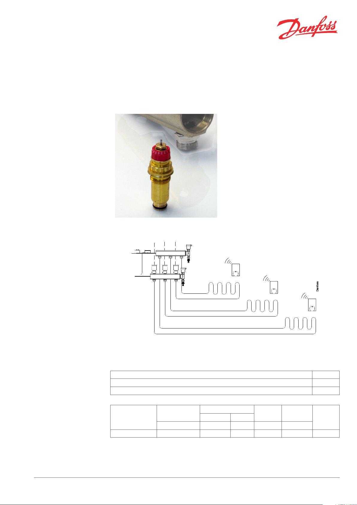
The integrated valve is designed for manifold
applications in combination with a system
connection piece.
Valve and connection piece are fitted to top and
bottom of manifolds with ½” connections.
The valve has RA 2000 connection for Danfoss
sensors and TWA thermal actuators.
The valve features an integrated presetting of
max. flow, which allows each heating circuit to be
balanced independantly.
Flow capacity is designed for conventional twopipe heating systems. The valve is mounted in
the return flow.
Floor heating manifold with integrated valve 013G0376 and TWA thermal actuator in return flow.
Code Nos. and Technical
Data
Danfoss Heating Solutions VDTVV202 © Danfoss 03/2011 1
Part Code no.
Integrated valve with RA 2000 connection 013G0376
Spare part: Gland seal, 10 pcs/pack 013G0290
Connection thread
G ½ A 120 0.05-0.2 0.6 16 10 013G0376
Max. water temp.
°C bar bar bar bar
Differential pressure
Rec. Tech
1)
Test press. Work. press.
Code no.
Data Sheet Integrated Valve with Presetting for Manifolds in Two-Pipe Heating Systems
Presetting
kv-value
1 2 3 4 5 6 7 N N
0.14 0.21 0.26 0.32 0.46 0.59 0.73 0.87 1.05
1)
The technical differential pressure indicates the upper limit for a proper valve function. In most twopipe systems the recommended differential pressure is sufficient. In order to achieve a noiseless
function we recommend in smaller systems to apply automatic bypass valves or automatic balancing
valves. If pump differential pressure exceeds the recommended max. valve differential pressure it is
recommended that an automatic balancing valve type ASV-P/PV is added to the system.
2)
The kv-values indicate the flow volume (Q) in m³/h at a pressure loss (∆p) across the valve of 1 bar;
. At setting N, the kv-value in accordance with EN 215 can be stated as Xp = 2 K. At lower preset
values, Xp will be reduced until approximately Xp 0.5 at presetting 1. The table shows the average
measured values for integrated valves with radiator. The kvs-values indicate the valve capacity, when
the valve is fully open.
2) 3)
k
vs
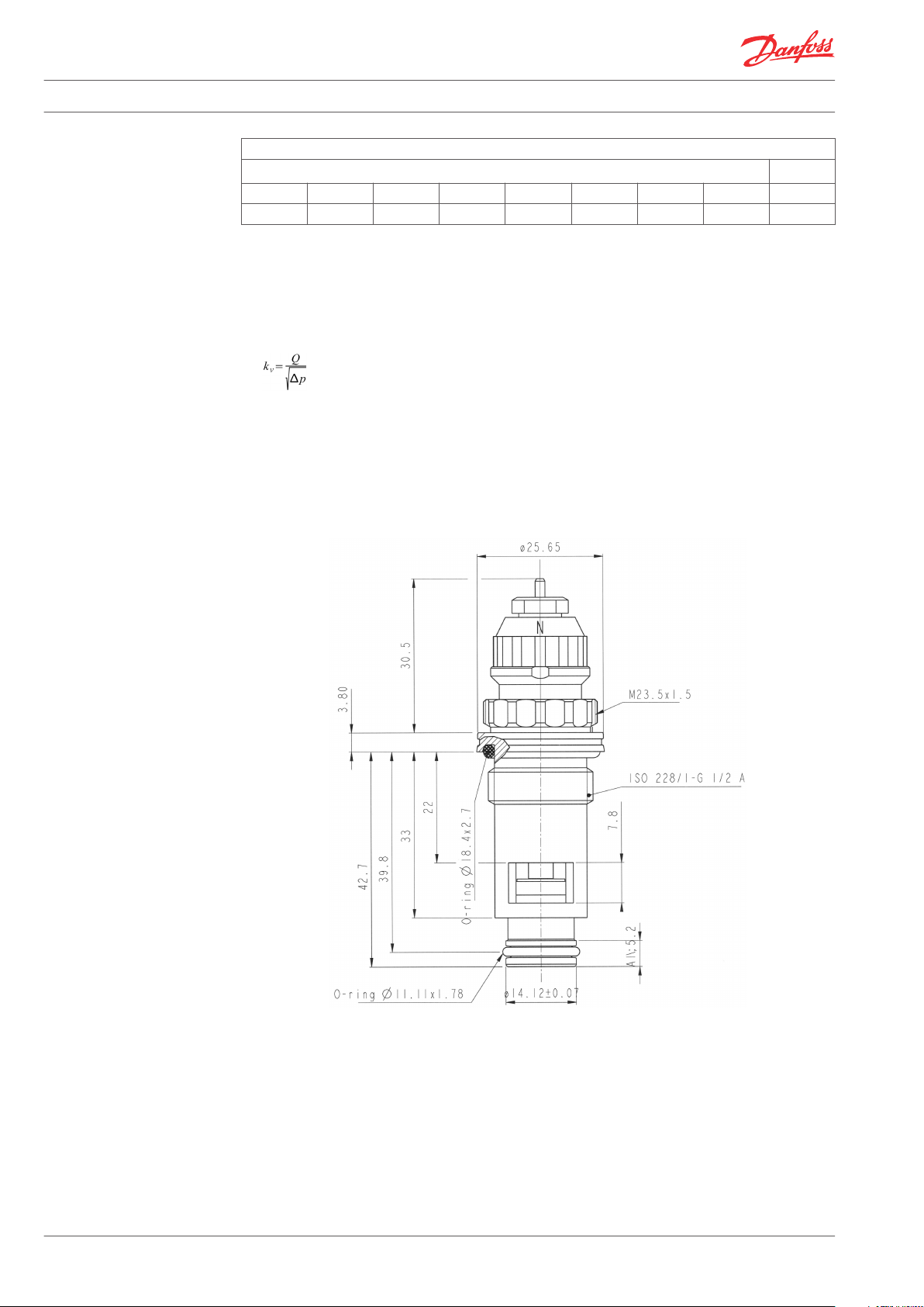
Design and Dimensions
Integrated valve 013G0376
2 VDTVV202 © Danfoss 03/2011 Danfoss Heating Solutions
3
1
2
3
Data Sheet Integrated Valve with Presetting for Manifolds in Two-Pipe Heating Systems
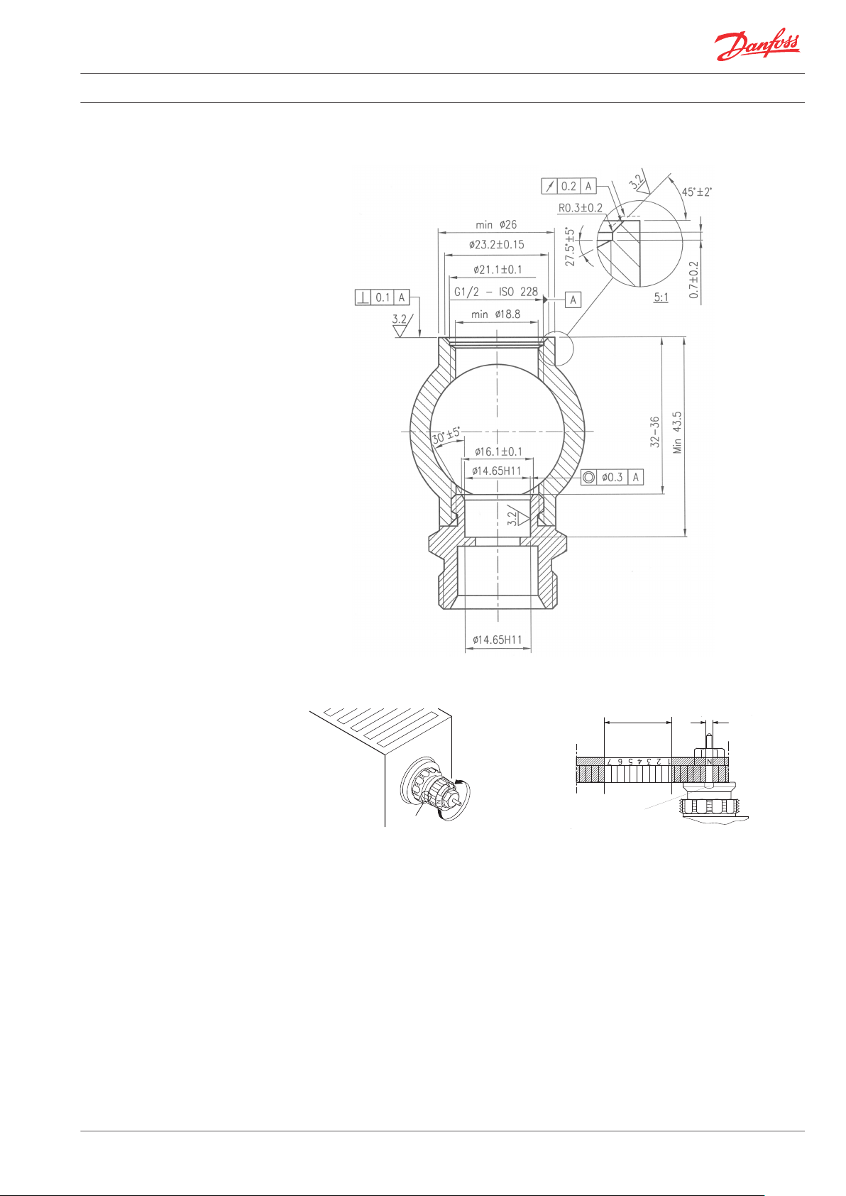
Manifold design and tolerances
Presetting
1. Presetting range
2. Factory setting and one-pipe system
3. Reference mark
The presetting values of the integrated valves
Presetting can be selected within the range of 1
to 7. At setting ‘N’ the valve is fully open. Setting
in the shaded areas of the drawing should be
avoided. Setting ‘N’ is used when flushing the
system.
can be adjusted easily and accurately without the
use of tools (factory setting: ‘N’):
When the sensor or the actuator is fitted, the
presetting is hidden and thus protected against
Remove the protective cap or the
▪
unintended alteration.
thermostatic sensor
Find the reference mark
▪
Turn the setting ring until the desired
▪
presetting number aligns with the reference
mark.
Danfoss Heating Solutions VDTVV202 © Danfoss 03/2011 3

Data Sheet Integrated Valve with Presetting for Manifolds in Two-Pipe Heating Systems
Materials in Contact with
Water
Capacities without Manifold
Valve body Ms 58
Valve seat Ms 58
Throttle nozzle PPS
Setting ring PBT
O-rings NBR / EPDM
Valve spindle PPS
Valve cone NBR
Pressure pin and valve spring Chrome steel
To avoid calcification and corrosion, it is
important for the composition of the circulating
water to comply with the VDI 2035 guidelines.
013G0376
Capacities at Xp = 2K measured without radiator and connection fittings.
4 VDTVV202 © Danfoss 03/2011 Danfoss Heating Solutions

1
2
3
Data Sheet Integrated Valve with Presetting for Manifolds in Two-Pipe Heating Systems
Mounting
1. Thread G ½ A
2. Protection cap thread
3. Setting ring
Fit valve in manifold and tighten by hand.
Tighten to 30 Nm using a 12-edge ring spanner,
KW 21.
Danfoss Heating Solutions VDTVV202 © Danfoss 03/2011 5

Data Sheet Integrated Valve with Presetting for Manifolds in Two-Pipe Heating Systems
6 VDTVV202 © Danfoss 03/2011 Danfoss Heating Solutions

Data Sheet Integrated Valve with Presetting for Manifolds in Two-Pipe Heating Systems
Danfoss Heating Solutions VDTVV202 © Danfoss 03/2011 7

Data Sheet Integrated Valve with Presetting for Manifolds in Two-Pipe Heating Systems
Danfoss A/S
Heating Solutions
Haarupvaenget 11
8600 Silkeborg
Denmark
Phone:+45 7488 8000
Fax: +45 7488 8100
Email: heating.solutions@danfoss.com
www.heating.danfoss.com
Danfoss can accept no responsibility for possible errors in catalogues, brochures and other printed material. Danfoss reserves the right to alter its products without notice. This also applies to products
already on order provided that such alterations can be made without subsequential changes being necessary in specifications already agreed. All trademarks in this material are property of the respective
companies. Danfoss and the Danfoss logotype are trademarks of Danfoss A/S. All rights reserved.
8 VDTVV202 © Danfoss 03/2011 Danfoss Heating Solutions
 Loading...