

Page 1
Technical Information
Integrated Automotive Control (AC)
for MP1 and H1P Single Pumps
www.danfoss.com
Page 2

Technical Information
Integrated Automotive Controls for H1 and MP1 Single Pumps
Revision history Table of revisions
Date Changed Rev
April 2020 Changed document number from 'BC00000213' and 'L1223856' to 'BC152986482596' and
added new model code options
August 2019 Added MP1 pump 0601
May 2017 Major update 0501
May 2014 Size 165 added DA
February 2014 Layout in DITA CMS CA
October 2013 Converted to Danfoss layout BA
January 2013 All frame sizes into one document AA
0703
2 | © Danfoss | April 2020 BC152986482596en-000703
Page 3

Technical Information
Integrated Automotive Controls for H1 and MP1 Single Pumps
Contents
General information
Automotive controls description................................................................................................................................................5
Targeted applications.....................................................................................................................................................................5
Hydrostatic propel methods........................................................................................................................................................ 5
Automotive transport mode...................................................................................................................................................5
Automotive ECO mode.............................................................................................................................................................5
Non-automotive work mode..................................................................................................................................................5
Creep-automotive work mode...............................................................................................................................................6
Static mode................................................................................................................................................................................... 6
Functional safety standards..........................................................................................................................................................6
Type A standards.........................................................................................................................................................................6
Type B1 standards.......................................................................................................................................................................6
Type B2 standards.......................................................................................................................................................................7
Type C standards.........................................................................................................................................................................7
Required hardware components................................................................................................................................................7
Functions
Function overview........................................................................................................................................................................... 8
Basic functions...................................................................................................................................................................................9
System mode selection.............................................................................................................................................................9
Mode transition control............................................................................................................................................................9
Drive pedal.................................................................................................................................................................................... 9
Engine speed potentiometer/hand throttle..................................................................................................................... 9
Inching............................................................................................................................................................................................ 9
Pump/engine rpm....................................................................................................................................................................10
Hydromotor rpm.......................................................................................................................................................................10
Temperature sensors...............................................................................................................................................................10
Pump profiling and ramping................................................................................................................................................10
Hydromotor profiling and ramping...................................................................................................................................10
Hydromotor brake pressure defeat (BPD) control........................................................................................................10
Maximum hydromotor torque at low vehicle speed...................................................................................................11
State and direction change...................................................................................................................................................11
Status LED....................................................................................................................................................................................11
Protection and safety functions................................................................................................................................................11
Start protection......................................................................................................................................................................... 11
Quick stop in automotive mode......................................................................................................................................... 11
Operator presence detection...............................................................................................................................................11
Hydromotor overspeed protection....................................................................................................................................11
Hydraulic system overheat protection............................................................................................................................. 12
Performance functions.................................................................................................................................................................12
ECO fuel saving mode.............................................................................................................................................................12
Cruise control.............................................................................................................................................................................12
Vehicle constant speed drive (CSD)...................................................................................................................................12
Vehicle speed limitation.........................................................................................................................................................12
Filter for drive pedal.................................................................................................................................................................12
Dynamic brake light.................................................................................................................................................................13
Automated park brake control............................................................................................................................................ 13
Reverse buzzer...........................................................................................................................................................................13
Vehicle speed dependent output.......................................................................................................................................13
Load independent pump displacement control (option AC2)................................................................................ 13
J1939 CAN subsystem data interface................................................................................................................................13
Engine control and protection
J1939 CAN engine interface.......................................................................................................................................................15
Kubota engine protocol.............................................................................................................................................................. 15
Engine anti-stall protection........................................................................................................................................................15
All range engine overspeed.......................................................................................................................................................15
Engine over speed protection with retarder........................................................................................................................15
Cold start protection.....................................................................................................................................................................15
Technical specifications
©
Danfoss | April 2020 BC152986482596en-000703 | 3
Page 4

Technical Information
Integrated Automotive Controls for H1 and MP1 Single Pumps
Contents
Automotive Control connection diagram.............................................................................................................................16
Battery and sensor voltage supply.......................................................................................................................................... 17
CAN communication.....................................................................................................................................................................18
Digital inputs................................................................................................................................................................................... 18
Forward-Neutral-Reverse (FNR) switch..................................................................................................................................18
Mode switch A and B.................................................................................................................................................................... 19
Analog Inputs..................................................................................................................................................................................20
Drive/Creep pedal..........................................................................................................................................................................20
General requirements and recommended settings of a pedal or potentiometer............................................20
Engine speed potentiometer/hand throttle........................................................................................................................ 20
Inch pedal......................................................................................................................................................................................... 21
Cruise control.................................................................................................................................................................................. 21
Pump rpm.........................................................................................................................................................................................22
Hydromotor rpm............................................................................................................................................................................22
PWM outputs...................................................................................................................................................................................23
Pump control...................................................................................................................................................................................23
Hydromotor control......................................................................................................................................................................23
Digital outputs................................................................................................................................................................................ 23
Hydromotor Brake Pressure Defeat (BPD) control.............................................................................................................24
Digital output A1 and A2.............................................................................................................................................................25
Environmental and protection characteristics....................................................................................................................25
Mating Connectors
Customer connectors (CC1, CC2 and CC3)........................................................................................................................... 27
PPC connector ................................................................................................................................................................................29
CAN connector................................................................................................................................................................................30
CAN bus adapter............................................................................................................................................................................ 30
MP1 pumps size 28-45cc model code
Automotive control parts for MP1...........................................................................................................................................32
H1 pumps size 45-250cc model code
Automotive control parts for H1P............................................................................................................................................34
4 | © Danfoss | April 2020 BC152986482596en-000703
Page 5

Technical Information
Integrated Automotive Controls for H1 and MP1 Single Pumps
General information
Automotive controls description
The Integrated Automotive Control solutions are designed to support single path hydrostatic
transmissions systems consisting of one pump (available sizes: MP1 28-45cc and H1P 45-250cc) and one
or more hydromotor. Danfoss offers several software configurations to cover the application demands.
With the pre-installed application software and easily changeable control parameters, it is possible to
tailor the vehicles driving behavior to the individual requirements of the customer. The Semi-AutoCalibration function for the pedals and a Quick-Start Guide with implemented Hyperlinks in the Service
tool will make changes and tuning more easily and effective.
Targeted applications
Automotive controls for H1 and MP1 pumps are targeted for the following applications.
Wheel loader
•
Telehandler
•
Dumper
•
Sweeper
•
Snow blower
•
Forestry machines
•
Hydrostatic propel methods
The application software offers different hydrostatic propel methods (defined as mode types).
Up to 4 system modes can be defined individually by parameter.
Automotive transport mode
Proportional pump and hydromotor displacement control.
The setpoint of the pump and hydromotor drive curves are given by the engine rpm. The engine rpm is
commanded by a drive pedal.
•
Drive pedal controls engine rpm
•
Engine rpm controls vehicle speed
•
Load dependent mode
•
Brake/inch signal reduces vehicle speed
•
Coast down when the drive pedal is released
Automotive ECO mode
The ECO fuel saving mode is designed for the Automotive Transport mode. It needs a CAN controlled
engine, an electric drive pedal and a larger pump displacement.
The ECO mode function reduces the engine rpm setpoint automatically when a vehicle speed is reached.
This function reduces fuel consumption and noise emission. The pump displacement will increase to
keep the vehicle speed on the same level with a reduced engine rpm. The ECO mode is automatically
switched off if the vehicle slows down or the driver releases the electric drive pedal.
The ECO mode is available in all Automotive Transport modes and can be enabled individually in each of
the four system modes.
Non-automotive work mode
Proportional pump and hydromotor displacement control.
The setpoint of the drive curves are given by the drive pedal command independent of the engine rpm.
The engine rpm is commanded by a handle throttle to fulfill the requirements of the work hydraulic.
©
Danfoss | April 2020 BC152986482596en-000703 | 5
Page 6

Technical Information
Integrated Automotive Controls for H1 and MP1 Single Pumps
General information
Drive pedal controls vehicle speed
•
Engine rpm is set separately with the hand throttle according to the requirements of work functions
•
Load independent mode
•
Brake/inch signal reduce vehicle speed
•
Vehicle speed limitation by the drive pedal (no roll down the hill)
•
Antistall protects the engine from overloading
•
Creep-automotive work mode
Mechanical controlled engines cannot command the engine rpm by a hand throttle.
The setpoint of the pump and hydromotor drive curves are given by the engine rpm, reduced by the
creep potentiometer. The engine rpm is commanded by a drive pedal.
Drive pedal controls vehicle speed
•
Load dependent mode
•
Creep potentiometer reduces the vehicle speed
•
Brake/inch signal reduces vehicle speed
•
Functional safety standards
Static mode
The engine rpm is commanded by a hand throttle to fulfill the requirements of the work functions.
The vehicle does not drive in this mode.
The AC controller fulfills the safety requirements according to the machine directive (2006/EC).
The design of this general purpose safety controller includes features required for sophisticated machine
control strategies. It is equally suited for use in safety related or general machine control applications. The
controllers support smart digital inputs. Device outputs can be individually controlled by the watchdog
processor.
The Safety Manual of the propel controller solutions is intended to guide the system integrator
concerning functional safety. The document describes a possible implementation of the needed safety
functions and is available on request. Please contact your local Danfoss representative to request the
Safety Manual.
Type A standards
This standard covers all general safety requirements that apply to all types of machines.
IEC 61508 Functional safety of electrical/electronic/programmable electronic safety-related systems
•
Type B1 standards
This standard covers safety and ergonomic design of machinery.
ISO 15998 Controller for Earth moving machinery
•
EN ISO 13849-1:2015 Safety of machinery; Safety-related parts of control systems Part 1 and 2
•
ISO 25119 Agriculture machinery (formerly EN 16590)
•
6 | © Danfoss | April 2020 BC152986482596en-000703
Page 7

Technical Information
Integrated Automotive Controls for H1 and MP1 Single Pumps
General information
Type B2 standards
This standard covers safety components and protective devices. For example: two-hand controls;
interlocking devices; pressure-sensitive devices; guards).
Type C standards
This standard covers detailed safety requirements for a particular machine or group of machines.
ISO 20474-2017 (formerly DIN/EN 474) Earth moving machinery
•
EN 1459-1:2017 Rough terrain trucks; Safety requirements and verification Part 1: Variable reach
•
trucks
EN 4254:2013 Agriculture machinery; Safety Part 1: General requirements
•
EU 167/2013 Agricultural and Forestry vehicles (tractor directive)
•
EU 1322/2014
‒
EU 68/2015
‒
EU 96/2015
‒
EU 208/2015
‒
EU 1788/2016
‒
Required hardware components
Engine
Mechanical or CAN controlled engines. CAN J1939 and proprietary Kubota protocol are supported.
Hydrostatic pumps
Load dependent pumps (NFPE) with embedded AC controller.
•
•
•
•
Hydraulic motors
Orbital hydraulic motors (fixed)
•
•
Axial piston hydraulic motors with zero degree capability
•
•
•
•
MP1 series: size 28, 32, 38 and 45cc
H1 series: size 45, 53, 60, 69, 78, 89, 100, 115, 130, 147, 165, 210 and 250cc
Speed sensor in the pump only for mechanically controlled engines
No pressure sensors required
OMS, OMT and OMV series: size 80-800cc
TMK, TMT and TMV series: size 160-800cc
Series 40 (fixed): size 25, 35, and 44cc
L/K series (variable, 2-position): size 25, 35, 38 and 45cc
H1B series (variable with pressure control PCOR): size 60, 80, 110, 160, 210 and 250cc
H1B series (variable with proportional control): size 60, 80, 110, 160, 210 and 250cc
©
Danfoss | April 2020 BC152986482596en-000703 | 7
Page 8
Technical Information
Integrated Automotive Controls for H1 and MP1 Single Pumps
Functions
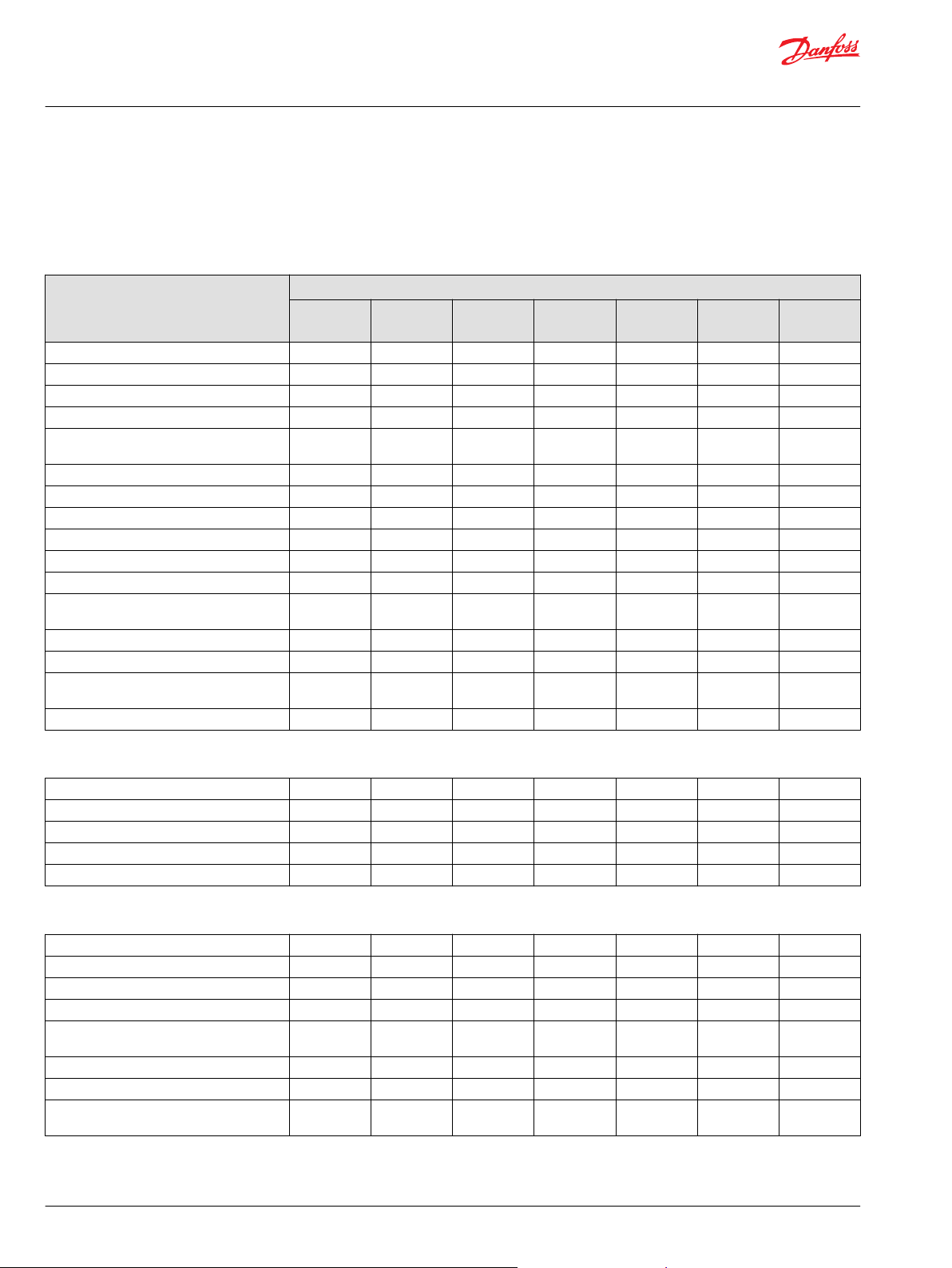
Function overview
The available functions for the individual software solution can be found in the table below. A more
detailed description of the individual functions can be found on the following pages.
Basic functions
Function Option code H1P / MP1
F1F
(AF1F)
Automotive Transport Mode x x x x x x x
Non-Automotive Work Mode x x x x x x x
Creep-Automotive Work Mode x x x x x x
4 Selectable System Modes x x x x x x x
Independent Profiling & Ramping for Pump
and Hydromotor
Mode Transition Control x x x x x x x
Drive Pedal with Filter Function x x x x x x x
Brake/Inch Pedal x x x x x x x
Engine Speed Potentiometer/Hand Throttle x x x x x x x
Engine & Hydromotor rpm sensor x x x x x x x
Creep Mode Potentiometer x x x x x x
Pressure Controlled (PCOR) Hydromotor
Control
Proportional Hydromotor Control x
Hydromotor Load Limiter x
Max. Hydromotor torque at low vehicle
speed
Status Information by LED blink code x x x x x x x
x x x x x x x
x x x x x x
x x x x x x x
F2J
(AF2J)
F1E
(AF1E)
F2E
(AF2E)
F3J
(AF3J)
F4J
(AF4J)
F6L
Protection and safety functions
Start Protection x x x x x x x
Quick Stop in Automotive Mode x x x x x x x
Operator Presence Detection x x x x x x x
Hydraulic motor Over Speed Protection x x x x x x x
Hydraulic Overheat protection x x x x x x x
Performance functions
Automotive ECO Mode x x x x x x
Cruise Control x x x
Constant Speed Drive (CSD) x x x x x x x
Vehicle speed Limitation x x x x x x x
Dynamic Brake Light Control by
Deceleration
Automatic Park Brake Control x x x x x x x
Reverse buzzer x x x x x x x
Vehicle speed dependent Output (load
Stabilizer)
x x x x x x x
x x x x x x x
8 | © Danfoss | April 2020 BC152986482596en-000703
Page 9

Technical Information
Integrated Automotive Controls for H1 and MP1 Single Pumps
Functions
Performance functions (continued)
CAN User Interface (e.g. Error messages,
Inputs…)
Load Independent Pump Displacement
Control (Option AC2)
Engine control and protection
Mechanical controlled Engines x x x x x x
CAN J1939 Engine rpm control x x x x x x x
Kubota CAN Engine rpm control x x
Engine Antistall protection x x x x x x x
Engine control and protection (continued)Pi
All range engine over speed protection x x x x x x x
Engine Over Speed Protection with Retarder x x x x x x x
Engine cold start protection x x x x x x x
x x x x x x x
x x
Basic functions
System mode selection
The mode switch defines which of the 4 system modes should be applied.
The mode switch has three digital inputs supplied with battery voltage or received via CAN message. For
diagnostic purpose one mode switch is redundant.
The mode change conditions can be defined by parameter.
Mode transition control
This function allows configuration of an application specific System Mode transition.
The System Mode change condition can be dependent on multiple factors including actual FNR
Direction, Drive Pedal Input, and Vehicle Speed.
Drive pedal
The drive pedal is used as the vehicle speed request.
Depending on the propel mode it can be the engine setpoint (automotive mode) or the pump and
hydromotor command (work mode).
The drive pedal has two redundant analogue signals, supplied with 5V sensor voltage or can received via
CAN (EEC2) standard message.
Engine speed potentiometer/hand throttle
The engine speed potentiometer is used as the engine setpoint in work mode.
The engine speed potentiometer has two redundant analogue signals, supplied with 5V sensor voltage
or can received via CAN (EEC2) standard message.
Inching
The inch function allows the operator to reduce the vehicle speed, stop the machine or keep the vehicle
speed low while rising the engine rpm to meet the flow demand of the work functions.
An increasing inch pedal signal will reduce the pump displacement, thus reducing vehicle speed.
©
Danfoss | April 2020 BC152986482596en-000703 | 9
Page 10

Technical Information
Integrated Automotive Controls for H1 and MP1 Single Pumps
Functions
There can be a combination brake/inch of the service brake with an additional sensor for an inch signal or
a separate inch pedal.
The inch pedal has two redundant analogue signals, supplied with 5V sensor voltage or can received via
CAN (EBC1) standard message.
Pump/engine rpm
The pre-installed pump rpm sensor is connected to calculate the pump/engine rpm.
The calculated engine rpm is the setpoint for the automotive drive curve. Optional the engine rpm signal
can received via CAN EEC1 message from the engine controller. In this case, a pump rpm sensor is not
required.
Hydromotor rpm
The hydromotor rpm is measured via a PPU (pulse pickup unit) in the hydromotor. With help of the gear
factor and wheel diameter a vehicle speed is calculated.
The hydromotor rpm is detected by a frequency input with signal level detection. It is supplied with the
5V sensor voltage.
The actual vehicle speed is send out via CAN CCVS message.
Temperature sensors
The temperature sensor integrated in the controller will measure the hydraulic oil temperature.
These functions are:
•
Protection of the complete hydrostatic system by reducing the pump flow (by pump command) at
extreme high temperatures according to user defined temperature curve.
•
Protection of the complete hydrostatic system by reducing the commanded engine rpm at low
temperatures according to a user defined temperature value. When the system has warmed up, the
engine speed limitation is no longer active.
The actual temperature is sent out via CAN TRF1 message.
Pump profiling and ramping
The pump solenoids are supplied by two PWM (pulse width modulation) output signals, independently
configured for the forward and reverse driving direction in each of the four system modes.
For each of the four system modes two independent profile curves for forward & reverse are available.
Hydromotor profiling and ramping
Proportional and 2-Position hydromotors can be controlled directly by a PWM output signal.
The hydromotor command can be defined by a constant value or a profile curve output, individually for
each of the four system modes and driving direction.
Hydromotor brake pressure defeat (BPD) control
The hydromotor BPD control is used in combination with a pressure controlled (PCOR) hydromotor
control.
This function prevents the activation of the internal hydromotor control pressure compensator (PCOR)
during deceleration events. The hydromotor BPD control is activated automatically.
10 | © Danfoss | April 2020 BC152986482596en-000703
Page 11

Technical Information
Integrated Automotive Controls for H1 and MP1 Single Pumps
Functions
Maximum hydromotor torque at low vehicle speed
This function will command the hydromotor to max displacement during low vehicle speed to provide
the maximum available torque.
If the defined vehicle speed is reached, the hydromotor will follow the original drive curve. A hydromotor
or vehicle speed sensor is required to detect the actual vehicle speed.
State and direction change
A driving direction change is always handled in a safe way.
The change request by the FNR switch will initiate the deceleration of the vehicle. The change of the
driving direction is only started, if the actual vehicle speed is below a threshold value.
Status LED
In case of an Error, the red status LED on the controller shows a blink code.
The green LED is continuously on if the controller is supplied with battery power.
Protection and safety functions
Start protection
The safety controlled vehicle start protection prevents commanded, unexpected or otherwise dangerous
vehicle movement after initial power on the engine.
The start protection is monitoring the following signals:
•
Engine rpm
•
Battery voltage
•
Error status
•
Inch calibration
•
FNR in neutral
Quick stop in automotive mode
When operating the vehicle in automotive transport mode, the controller will use the engine rpm as the
setpoint. The electric drive pedal position (out of the deadband) is used as an enable signal.
The driver must press the drive pedal and the engine rpm must rise to move the vehicle. If the driver
releases the drive pedal fully (drive pedal return into the deadband), the pump current will decrease with
an adjustable ramp to a defined value. The vehicle will decelerate much faster compared to the normal
behavior.
Operator presence detection
Driving the vehicle is only allowed if the operator is seated on the driver seat. A programmable time delay
will trigger vehicle shut down if the driver leaves the seat for a longer period of time.
Before a pre-warning signal is shown, there is a possibility to override the seat switch if the driver is
pressing the drive pedal.
Hydromotor overspeed protection
The hydromotor overspeed protection prevents the hydromotor from over speeding by decreasing
pump displacement or increasing hydromotor displacement.
The hydromotor rpm speed limit, is user defined and valid in all four system modes when activated.
©
Danfoss | April 2020 BC152986482596en-000703 | 11
Page 12

Technical Information
Integrated Automotive Controls for H1 and MP1 Single Pumps
Functions
Hydraulic system overheat protection
The temperature sensor in controller will measure the hydraulic oil temperature.
The function protects the complete hydrostatic system by reducing the pump flow (by pump command)
at extreme high temperatures according to user defined temperature curve.
Performance functions
ECO fuel saving mode
The ECO fuel saving mode is designed for the automotive transport mode. It needs a CAN controlled
engine (TSC1 & EEC2), an electric drive pedal and a larger pump displacement.
The ECO mode function reduces the engine rpm setpoint (TSC1) automatically when the defined vehicle
speed is reached. This will reduce the fuel consumption and noise emission. The pump displacement will
be increased to keep the vehicle speed on the same level with a reduced engine rpm. The ECO mode is
automatically switched off if the vehicle slows down or the driver releases the electric drive pedal.
The ECO mode is available in all automotive transport modes and can enabled individually in each of the
four system modes.
Cruise control
The cruise control will keep the vehicle speed constant during driving.
The driver can release the drive pedal if cruise control is enabled. The software will keep the vehicle
speed constant by adjusting the setpoint.
An actuation of the drive pedal above the captured value (higher wins) will accelerate the vehicle.
If the drive pedal is released again, the vehicle speed will return to the captured value.
If cruise control is enabled, the driver can increase or decrease the vehicle speed by pressing a button.
The speed steps and trigger time can be set by parameter.
Cruise control is working only in forward driving direction, all cruise states are send out via proprietary
CAN message.
Vehicle constant speed drive (CSD)
The CSD function will allow driving with a constant vehicle speed, independent of the engine rpm.
If the actual vehicle speed differs from the commanded speed, the CSD function will adjust the pump and
hydromotor command to compensate the speed difference. The speed setpoint usually comes from an
electric drive pedal. For the feedback a hydromotor or vehicle speed sensor is required.
Vehicle speed limitation
The vehicle speed limitation prevents the machine from over-speeding.
It can configured separately for each system mode and driving direction. The vehicle speed is calculated
from the hydromotor rpm, the gear factor and the wheel diameter.
Filter for drive pedal
When driving over a field or other rough terrain, the vehicle is shaking and the driver has no chance to
keep the electric drive pedal constant in one position, the filter function for the drive pedal is able to
mitigate this short movement.
The filter can configure individually in each system mode.
12 | © Danfoss | April 2020 BC152986482596en-000703
Page 13

Technical Information
Integrated Automotive Controls for H1 and MP1 Single Pumps
Functions
Dynamic brake light
The digital brake light output is switched on if the inch/brake pedal command exceeds a user defined
value or the calculated deceleration is too high (measured by the hydromotor rpm sensor).
This function applies the brake light if the vehicle decelerates by the hydrostatic system. There will be an
on/off delay to avoid flickering of the brake lights.
Automated park brake control
The park brake can applied automatically by CAN message RCI (PGN FF30 - Signal Brake Remote Request)
or the following:
Software machine state in STOP mode
•
Actual pump valve current below user defined value
•
Actual inch pedal command exceeds user defined value
•
Actual vehicle speed is lower than a user defined value
•
Delay times for park brake applied and released are individually configurable.
The park brake logic support the “negative brakes” and is connected in closed loop, that means + and –
are connected to the controller.
Brake applied = output is switched off
Brake released = output is switched on
Reverse buzzer
The reverse buzzer is switched on if the FNR is set to reverse.
Vehicle speed dependent output
The vehicle speed dependent output signal toggles a digital output when the actual vehicle speed
exceeds a user defined value. It can be used as a e.g. speed dependent load stabilizer.
Load independent pump displacement control (option AC2)
The load independent pump displacement control maintains commanded swash plate position
independent of load (Non-Automotive, similar to EDC behavior) using electronic feedback from the
pump swash plate angle sensor.
The function can be enabled individually for each of the four system modes. Two independent profile
curves for forward & reverse are available.
J1939 CAN subsystem data interface
The AC control can exchange information with the vehicle system via the CAN bus.
The following standard messages are supported:
•
TSC1 (torque/speed control)
•
EEC1 (pump/engine rpm)
•
EEC2 (drive pedal)
•
EBC1 (inch pedal)
•
ETC5 (FNR)
•
VH (vehicle hours)
•
RCI (brake remote control)
•
OPS (operator presence)
•
CC VS (vehicle speed)
•
VEP1 (battery voltage)
•
TRF1 (oil temperature)
©
Danfoss | April 2020 BC152986482596en-000703 | 13
Page 14

Technical Information
Integrated Automotive Controls for H1 and MP1 Single Pumps
Functions
Additional Danfoss Power Solutions specific (proprietary) messages are available to share information
about mode switches, hydromotor rpm, transmission state and error messages. All messages can be
individually activated and designated for usage.
14 | © Danfoss | April 2020 BC152986482596en-000703
Page 15

Technical Information
Integrated Automotive Controls for H1 and MP1 Single Pumps
Engine control and protection
J1939 CAN engine interface
The AC controller can exchange information with the engine via the CAN J1939 protocol (TSC1 message)
CAN messages can be individually activated and designated for usage.
The following functions and standard messages are provided:
•
Engine speed control
•
Engine anti-stall protection
•
All range engine overspeed protection
•
Engine overspeed protection with retarder function
•
Cold start protection
Kubota engine protocol
The AC controller supports the properitary Kubota Engine protocol. It is available on request. Please
contact your local Danfoss representative.
Engine anti-stall protection
The engine anti-stall protection prevents the engine from being stalled due to overload.
The commanded engine rpm (TSC1) is compared with the measured engine rpm. If the engine is
drooped, the engine anti-stall function will reduce the hydrostatic propel command to reduce the engine
load and the vehicle speed.
The engine anti-stall function can be individually enabled for each system mode and is configurable. It
works only with CAN controlled engines.
All range engine overspeed
The engine rpm is monitored in all driving situations, but only if the vehicle is moving. Therefore a speed
sensor in the hydraulic motor is mandatory.
When the system detects an engine overspeed situation, the pump will swivel out. That will limit the
deceleration of the vehicle. The driver must use the service brake to reduce the vehicle speed.
The engine rpm range for the overspeed detection can be defined by parameter. Time ramps for
activation and de-activation of the function are available.
Engine over speed protection with retarder
The engine rpm dependent retarder control toggles a digital output when the actual engine rpm exceeds
a user defined level. The retarder can activate a valve of the work hydraulic to give load to engine and
prevent an over speeding.
Cold start protection
An integrated temperature sensor will measure the system temperature.
If the temperature is lower than a user defined level, the engine rpm command (TSC1) is limited until the
system is warmed up to protect the engine and the hydraulic system.
©
Danfoss | April 2020 BC152986482596en-000703 | 15
Page 16

Contact capability min. 10A
Melting fuse 16A
1
2
Functional options
3
Reverse Motion
Fault LED (must be LED, min Current 5mA)
Park Brake
FNR Reverse LED
FNR set to Reverse
FNR Forward LED
Vehicle Speed dependent Output
Brake Light
Engine Speed dependent Output (Retarder)
FNR set to Reverse
Rv
Rv
Engine RPM Setpoint
System Pressure Sensor
Batt.
12/24V DC
+ -
S1
1
F1
2
Terminals
Batt. (+)
Terminals
Batt. (-)
1
2
3
4
5
6
DEUTSCH connector
DTM/6 pin
Sensor A (+)
Analog Input A
Sensor A (-)
Sensor B (-)
PPC
Analog Input B
Sensor B (+)
1
2
3
DEUTSCH connector
DTM/3 pin
CAN High
CAN Low
CAN Shield
CAN
1
2
3
4
5
6
DEUTSCH connector
DTM/6 pin
PWM C1 (+)
PWM C2 (+)
Digital Output A1 (+)
Digital Output A2 (-)
PSC
PWM C2 (-)
PWM C1 (-)
1
2
3
DEUTSCH connector
DTM/3 pin
Sensor (+)
Pump RPM Input (Frequency)
Sensor (-)
PPU
CC1p01
CC1p02
Motor RPM/Direction
CC1p05
1
2
3
4
5
6
7
8
9
10
11
12
DEUTSCH connector
DTM/12 pin
Inch Input (Analog-Red)
Mode Switch B Input (Digital-Nom)
Motor PROP/PCOR Output (PWM)
Motor Direction Input (Analog)
Sensor (+)
Sensor (-)
Inch Input (Analog-Nom)
Motor BPD Output (Digital)
Digital Output B2 (-)
Digital Output B1 (+)
Mode Switch A Input (Digital)
Mode Switch B Input (Digital-Red)
CC2
1
2
3
4
5
6
7
8
9
10
11
12
DEUTSCH connector
DTM/12 pin
Battery (-)
Battery (+)
Sensor (+)
Sensor (-)
Motor RPM Input (Frequency)
Forward Input (Digital)
Reverse Input (Digital)
Sensor (+)
Sensor (-)
Drive Pedal Input (Analog-Nom)
Drive Pedal Input (Analog-Red)
Neutral Input (Digital)
CC1
CC2p04
CC1p06
CC1p12
CC1p07
Rv
Rv
Drive/Creep/Rocker
Pedal
CC1p10
CAN Bus
CANp01
CANp02
CANp03
PSCp01
PSCp06
PSCp02
PSCp05
C1
C2
Displacement
Control Pump
Pump RPM
PPUp02
Mode Switch B
CC2p02
BPD
PCOR
CC2p03
CC2p08
Displacement
Control Motor
Rv
Rv
Inch Pedal (redundant)
CC2p07
Alternative: Brake
Pressure Sensor
CC2p11
CC2p10
CC2p09
CC1p03
CC1p04
CC1p08
CC1p09
PPUp03
PPUp01
CC2p05
CC2p06
CC2p01
CC2p12
CC1p11
Mode Switch A
Nominal
1
2
DEUTSCH connector
DT/2 pin
CC3
CC3p01
CC3p02
3
3
User defined
Outputs
PPCp01
PPCp05
PPCp03
PPCp02
Alternative:
Cruise Control
3k3
1k01k0
Set (+) / Stop / Resume (-)
Alternative to
Neutral Seat Switch or
Hand Brake Switch
FNR
Switch
R
N
F
User defined
Outputs
PPCp04
PPCp06
User defined
Inputs
3
CC2p05
CC2p06
1k0
Technical Information
Integrated Automotive Controls for H1 and MP1 Single Pumps
Technical specifications
Automotive Control connection diagram
16 | © Danfoss | April 2020 BC152986482596en-000703
Page 17

Technical Information
Integrated Automotive Controls for H1 and MP1 Single Pumps
Technical specifications
Battery and sensor voltage supply
The AC can be supplied with 12 or 24 VDC depending on the control type.
CC1: 01 Battery (-) Power supply input from battery
CC1: 02 Battery (+) Power supply input from battery
CC1:03; CC1:08; PPC:01; PPC:06; PPU:1; CC2:05 Sensor supply voltage (+5 V)
CC1:04; CC1:09; PPC:03; PPC: 04; PPU:3; CC2:06 Sensor supply voltage (-)
All (-) pins are internally connected.
The 5 V sensor supply is internally generated. The sensor supply is protected against overload and reverse
polarity connection.
For more information about a pinout description, see Customer connectors (CC1, CC2 and CC3).
Supply characteristics
Parameter Minimum Maximum
Battery supply current — 12 A
Recommended fuse size — 16 A
Supply voltage range: rated 12 V 9 V
Supply voltage range: rated 12 V 18 V
Permanent supply voltage range 9 V
Rated 12 V range 9 V
Rated 24 V range 18 V
Permanent reverse voltage protection — -36 V
Sensor supply voltage range (internal) 4.825 V
Sensor supply current — 1 A
*
Maximum 1 A for all sensors together.
DC
DC
DC
DC
DC
DC
16 V
DC
32 V
DC
36 V
DC
16 V
DC
32 V
DC
5.075 V
*
DC
DC
©
Danfoss | April 2020 BC152986482596en-000703 | 17
Page 18

CC1p06
CC1p12
CC1p07
FNR
F
R
N
+ Battery
Supply
P301 427
Technical Information
Integrated Automotive Controls for H1 and MP1 Single Pumps
Technical specifications
CAN communication
The AC Control can exchange information with the vehicle system via CAN bus. CAN communication
baudrate is 250 kBaud. The physical (hardware) layer operates using the CAN 2.0B specification according
to ISO 11898-2, high speed. The CAN interface is even used for application software downloads and
parameter settings.
CAN:01 CAN High Communication connection for CAN – High line
CAN:02 CAN Low Communication connection for CAN – Low line
CAN:03 CAN Shield Communication connection for CAN – Shield
There is no internal termination resistor installed.
Digital inputs
The digital inputs switched to battery supplied 12 or 24 V DC.
Parameter Minimum Maximum
Rising voltage threshold
Falling voltage threshold
Input impedance 13.4 kΩ 13.8 kΩ
1
A digital input is guaranteed to be read as high if the voltage is > 7 V
2
A digital input is guaranteed to be read as low if the voltage is below 1.66 V DC
1
2
- 7.0 V DC
1.66 V DC -
For more information about pinning description, see Customer connectors (CC1, CC2 and CC3) on page
27.
Forward-Neutral-Reverse (FNR) switch
The FNR switch selects the driving direction, switched to battery supplied at 12 or 24 V DC. Different
configurations can be used. Please consider the required performance level when choosing an option.
Held signal (switch)
•
Monetary signal (push button)
•
2 pin FNR
•
3 pin FNR
•
2 pin FNR with seat switch or hand brake option
•
CC1:06 FNR Forward Input Digital input for forward driving direction
CC1:07 FNR Reverse Input Digital input for reverse driving direction
CC1:12 FNR Neutral Input Digital input for neutral driving direction
FNR
18 | © Danfoss | April 2020 BC152986482596en-000703
Page 19

CC2p11
+ Battery
Supply
Mode Switch A
P301 430
P301 431
CC2p02
CC2p12
+ Battery
Supply
Nominal
Redundant
Mode Switch B
Technical Information
Integrated Automotive Controls for H1 and MP1 Single Pumps
Technical specifications
Mode switch A and B
The mode switches are switched to battery supply (12/24 VDC) and select the four possible system modes
according to the table below:
Modes and selection
Mode Switch System mode
Mode 1 Mode 2 Mode 3 Mode 4
A Low Low High High
B
CC2:11 Mode Switch A Input Digital input for mode switch A
CC2:02 Mode Switch B Input (Nominal) Digital input for mode switch B (nominal)
CC2:12 Mode switch B Input (Redundant) Digital input for mode switch B (redundant)
Mode switch A
Nominal Low High Low High
Redundant High Low High Low
Mode switch B
©
Danfoss | April 2020 BC152986482596en-000703 | 19
Page 20

Rv
Rv
Nominal
Sensor supply
Ground
Rv
Rv
Redundant
P301 227
Technical Information
Integrated Automotive Controls for H1 and MP1 Single Pumps
Technical specifications
Analog Inputs
The analog inputs are supplied with the internal sensor voltage by the AC control.
Analog inputs
Parameter Minimum Maximum
Input voltage range 0.08 V
Resolution (4096 steps) — 12 Bit
Input impedance 230 kΩ 236 kΩ
Drive/Creep pedal
The drive pedal is used as the vehicle speed request. Depending on the propel mode it can be the engine
setpoint (Automotive mode) or the pump & hydromotor command (work mode).
The drive pedal signal can be configured and sent by the AC as CAN Engine Speed Command for the
J1939-CAN message TSC1 or proprietary Kubota Protocol.
CC1:08 Sensor (+) Sensor supply (+)
CC1:09 Sensor (-) Sensor supply (-) – direct GROUND connection
DC
5.26 V
DC
CC1:10 Drive Pedal Input (Nominal) Nominal analog input for creep/drive pedal as the command
signal
CC1:11 Drive Pedal Input (Redundant) Redundant analog input for drive/creep pedal for diagnostic
purpose
General requirements and recommended settings of a pedal or potentiometer
The pedal must be supplied with AC sensor supply voltage and must not exceed the maximum
•
output current (overload).
This pedal must produce two electrically independent output signals that are in direct correlation
•
with each other. The difference of the two input signals should be 500 mV. The redundant tolerance
should be set to +/- 200 mV.
The first output signal is used as the source of pedal position signal. It must rise when the pedal is
•
pressed. The second output signal is used for diagnostic purposes.
The voltage range of the output signals should not be lower than 5% and not higher than 95% of
•
sensor voltage. Upper and lower voltage limits to pedal supply are requested for wire-fault detection.
Engine speed potentiometer/hand throttle
The engine speed potentiometer is used as the engine setpoint in work mode.
The engine speed potentiometer has two redundant analogue signals, supplied with 5V sensor voltage.
PPC:01 Sensor A(+) Sensor supply (+5V)
20 | © Danfoss | April 2020 BC152986482596en-000703
Page 21

Rv
Rv
Nominal
Sensor supply
Ground
Rv
Rv
Redundant
P301 227
P
U
Inch Pressure
Sensor
CC2p05
CC2p01
CC2p07
CC2p07
P301 433
Technical Information
Integrated Automotive Controls for H1 and MP1 Single Pumps
Technical specifications
PPC:06 Sensor B(+) Sensor supply (+5V)
PPC:03 Sensor A(-) Sensor supply (-) – direct GROUND connection
PPC:04 Sensor B(-) Sensor supply (-) – direct GROUND connection
Inch pedal
PPC:02 Engine speed potentiometer
(Nominal)
PPC:05 Engine Speed Potentiometer
(Redundant)
Nominal analog input for Engine Speed Potentiometer
as the command signal
Redundant analog input for Engine Speed
Potentiometer for diagnostic purposes
The inch function allows the operator to reduce the vehicle speed, stop the machine or keep the vehicle
speed low while raising the engine rpm to meet the flow demand of the work functions.
An increasing inch pedal signal will reduce the pump displacement, thus reducing vehicle speed. There
can be a combination brake/inch of the service brake with an additional sensor for an inch signal or a
separate Inch pedal, supplied with 5V sensor voltage.
CC2:05 Sensor (+) Sensor supply (+)
CC2:06 Sensor (-) Sensor supply (-) – direct GROUND connection
CC2:07 Inch Pedal Input (Nominal) Nominal analog input for the inch pedal as the command
signal
CC2:01 Inch Pedal Input (Redundant) Redundant analog input for inch pedal for diagnostic purposes
Example of a brake/Inch pedal with pressure sensor
Cruise control
The cruise control will keep the vehicle speed constant during driving. The driver has three buttons “Set”
“Stop” and “Resume.” The resistor matrix is supplied with 5V sensor voltage.
CC2:05 Sensor (+) Sensor supply (+5V)
CC2:06 Sensor (-) Sensor supply (-) – direct GROUND connection
CC2:04 Cruise Input Analog input for cruise control buttons
©
Danfoss | April 2020 BC152986482596en-000703 | 21
Page 22

n/dir
+
-
n
dir
CC1p03
CC1p04
CC1p05
CC2p04
P301 432
1
f/U
Technical Information
Integrated Automotive Controls for H1 and MP1 Single Pumps
Technical specifications
Analog input
Parameter Minimum Maximum
Input voltage range 0.08 V
Resolution (4096 steps) — 12 Bit
*
Pump rpm
Input impedance
*
15 kΩ to sensor supply, 14.1 kΩ to Ground
The engine rpm is measured via a PPU (pulse pickup unit) in the pump. Optionally, the signal can be
received via CAN EEC1 message.
The pump rpm is detected by a frequency input. It is supplied with the 5V sensor voltage. It is only
useable with the Danfoss PPU sensor BC152886482203. When using the sensor, the wiring is part of the
cable harness on the pump.
DC
— —
5.26 V
DC
PPU:01 Sensor (+) Sensor supply (+5V)
PPU:03 Sensor (-) Sensor supply (-) – direct GROUND connection
PPU:02 Pump rpm Frequency input for pump rpm sensor
Hydromotor rpm
The hydromotor rpm is measured via a PPU in the hydromotor. With help of the gear factor and wheel
diameter a vehicle speed is calculated.
The hydromotor rpm is detected by a frequency input with signal level detection. It is supplied with the
5V sensor voltage.
CC1:03 Sensor (+) Sensor supply (+5V)
CC1:04 Sensor (-) Sensor supply (-) – direct GROUND connection
CC1:05 Hydromotor rpm Frequency input for hydromotor rpm sensor
Frequency input (hydromotor rpm)
Parameter Minimum Maximum
Rising voltage threshold (middle range)
Falling voltage threshold (middle range)
22 | © Danfoss | April 2020 BC152986482596en-000703
1)
2)
2.0 V
0.74 V
DC
DC
3.5 V
—
DC
Page 23

Technical Information
Integrated Automotive Controls for H1 and MP1 Single Pumps
Technical specifications
Frequency input (hydromotor rpm) (continued)
Parameter Minimum Maximum
3)
PWM outputs
Input impedance
Frequency range (in steps of 1 Hz) 0 Hz 10 000 Hz
1)
The frequency input is guaranteed to be read as high if the voltage is > 3.5 V
2)
The frequency input is guaranteed to be read as low if the voltage is < 0.74 V.
3)
15 kΩ to sensor supply, 13.5 kΩ to GND
The PWM outputs switch to battery supply (12/24 V).
PWM output
Parameter Minimum Maximum
Proportional current 0 A 3.0 A
Output voltage — Supply
PWM frequency 33 Hz 200 Hz
7.0 kΩ 7.21 kΩ
Pump control
Hydromotor control
Digital outputs
The pump solenoids are supplied by two PWM output signals. The low side (-) is connected via a digital
output, switching to ground. The wiring is part of the cable harness on the pump.
PSC:01: Pump C2 driver (+) Proportional output (+) for the pump solenoid C1; PWM signal from
battery supply (12/24 V)
PSC:06 Pump C1 driver (-) Low side switch (-) for the pump solenoid C1; switch to GND
PSC:02 Pump C2 driver (+) Proportional output (+) for the pump solenoid C2; PWM signal from
battery supply (12/24 V)
PSC:05 Pump C2 driver (-) Low side switch (-) for the pump solenoid C2; switch to GND
The hydromotor solenoid is supplied by a PWM output signal. Proportional and 2-Position hydromotors
can be controlled directly. The low side (-) is connected directly to ground.
CC2:02 Hydromotor driver
(+)
Proportional output (+) for the hydromotor solenoid; PWM signal from
battery supply (12/24 V)
The digital outputs can switch to battery supply (12/24 V) or to ground.
Parameter Minimum Maximum
Output current 0 A 3 A
Output voltage CC3:01 (A1); CC2:08 (BPD); CC2:10 (B1) - Battery supply
Output voltage CC3:02 (A2); CC2:09 (B2) Ground -
©
Danfoss | April 2020 BC152986482596en-000703 | 23
Page 24

Technical Information
Integrated Automotive Controls for H1 and MP1 Single Pumps
Technical specifications
Hydromotor Brake Pressure Defeat (BPD) control
The hydromotor BPD control is used in combination with a pressure controlled (PCOR) hydromotor
control.
The hydromotor BPD control prevents the activation of the internal hydromotor control pressure
compensator (PCOR) during deceleration events.
CCC2:08 Hydromotor BPD
Driver
Digital output for the brake pressure defeat (BPD) valve. Switched to
battery (+) supply (12/24 V).
24 | © Danfoss | April 2020 BC152986482596en-000703
Page 25

12 V
DC
+ -
1
+ -
P006 091
12 V
DC
1
Technical Information
Integrated Automotive Controls for H1 and MP1 Single Pumps
Technical specifications
Digital output A1 and A2
The digital outputs can be used as single outputs (open loop - switch to battery supply or GND) or in
closed loop.
The outputs can be configured individually to operate as:
Brake light control
•
Status signal (error LED)
•
Reverse motion signal
•
Engine speed dependent retarder control
•
FNR in reverse signal
•
Vehicle speed dependent signal
•
Cruise control on
•
Park brake control
•
CC2:09 Digital output B2 (-) Digital output - switched to GND (-)
CC2:10 Digital output B1 (+) Digital output - switched to battery (+) supply
CC3:01 A1 (+) Digital output – switched to battery (+) supply
CC3:02 A2 (-) Digital output – switched to GND (-)
Open loop (left) and closed loop (right)
Depending on the required performance level, safety-relevant functions (like brake light control, park
brake control, etc.) must be connected in closed loop.
The current feedback A2 (-) and B2 (-) are actively monitored; a detected error will result in SAFE state.
Environmental and protection characteristics
Parameter Standard description
Short circuit All inputs and outputs will withstand continuous short circuit to all other leads. When
EMC-Immunity (EMI)
EMC-Emission (RFI)
ESD
the short circuit is removed the unit returns to normal function.
EN 61000-6-2 (100 V/m)
EMC generic standard for immunity, industrial environment - incl. 1 kHz w/AM 80%
EN 61000-6-3
EMC generic standard for emission, residential and industrial environments
EN 12895 for industrial trucks
EN 61000-4-2
Electrostatic discharge immunity test Level 4
Direct contact discharge to connector pins
©
Danfoss | April 2020 BC152986482596en-000703 | 25
Page 26

Technical Information
Integrated Automotive Controls for H1 and MP1 Single Pumps
Technical specifications
Parameter Standard description
Automotive transients ISO 7637 / 1-3
Temp/Volt/Humidity IEC 60068-2-38 (-40 to 104° C)
Cold test IEC 60068-2-1 AD
Dry heat IEC 60068-2-2 BD
Ice water shock ISO 16750-4
Salt mist IEC 60068-2-11 test Ka
IP67 and IPX9K
*
with installed plug
*
IEC 60529 and DIN 40050 part 9 (valid for control only)
26 | © Danfoss | April 2020 BC152986482596en-000703
Page 27

P301 711
WARRANTY VOID IF REMOVED
CAN PPC
PSC
PPU
CC2
CC1
CC3
Technical Information
Integrated Automotive Controls for H1 and MP1 Single Pumps
Mating Connectors
Customer connectors (CC1, CC2 and CC3)
CC1 connector
CC1 connector DEUTSCH DTM, 12-pin
1. Battery (-)
2. Battery (+)
3. Sensor (+)
4. Sensor (-)
5. Hydromotor rpm input (frequency)
6. Forward input (digital)
7. Reverse input (digital)
8. Sensor (+)
9. Sensor (-)
10. Drive pedal input (analog-nominal)
11. Drive pedal input (analog-redundant)
12. Neutral input (digital)
©
Danfoss | April 2020 BC152986482596en-000703 | 27
Page 28

P301 712
WARRANTY VOID IF REMOVED
CAN PPC
PSC
PPU
CC2
CC1
CC3
Technical Information
Integrated Automotive Controls for H1 and MP1 Single Pumps
Mating Connectors
CC2 connector
CC2 connector DEUTSCH DTM, 12-pin
1. Inch input (analog redundant)
2. Mode switch B input (digital nominal)
3. Hydromotor PROP/PCOR output (PWM)
4. Cruise control input (analog)
5. Sensor (+)
6. Sensor (–)
7. Inch input (analog nominal)
8. Hydromotor BPD output (digital)
9. Digital output B2 (–)
10. Digital output B1 (+)
11. Mode switch A input (digital)
12. Mode switch B input (digital redundant)
There are 2 available kits, differentiated by customer wire diameter, containing both CC1 and CC2 mating
connectors.
CC1 and CC2 connectors kits information
Kit Name Lead wire diameter Material No.
Assembly bag with 2 DEUTSCH connectors
DTM06 12-SA and DTM06 12-SB
Black/Grey and gold plated pins
0.5-1.0 mm² (16-20 AWG)
0.2-0.5 mm² (20-24 AWG) {recommended}
10102023
10100945
28 | © Danfoss | April 2020 BC152986482596en-000703
Page 29

P301 715
WARRANTY VOID IF REMOVED
CAN PPC
PSC
PPU
CC2
CC1
CC3
P301 714
WARRANTY VOID IF REMOVED
CAN PPC
PSC
PPU
CC2
CC1
CC3
Technical Information
Integrated Automotive Controls for H1 and MP1 Single Pumps
Mating Connectors
CC3 connector
CC3 connector DEUTSCH DT, 2-pin
PPC connector
1. Digital output A1 (+)
2. Digital output A2 (–)
CC3 connector DEUTSCH kit information
Kit Name Lead wire diameter Material No.
Assembly bag with 1 DEUTSCH connector
0.5-2.0 mm² (14-20 AWG)
11070531
DT04 2P
Grey and gold plated pins
PPC connector DEUTSCH DTM, 6-pin
©
Danfoss | April 2020 BC152986482596en-000703 | 29
1. Sensor A (+)
2. Analog input A
3. Sensor A (-)
Page 30

P301 716
WARRANTY VOID IF REMOVED
CAN PPC
PSC
PPU
CC2
CC1
CC3
AC Controller CG 150 CAN USB Gateway
P003 551E
120Ω
CAN Bus
Batt.
12/24VDC
+-
F
1A
1
2
3
DEUTSCH connector
DTM06 3 pin
CAN High
120 ohm
CAN Low
CAN Shield
nc
CAN Low
Ground
nc
Shield
nc
CAN High
nc
Power Supply (+)
1
2
3
4
5
6
7
8
9
female D-SUB connector
9 pin
P301 429E
Technical Information
Integrated Automotive Controls for H1 and MP1 Single Pumps
Mating Connectors
4. Sensor B (-)
5. Analog input B
6. Sensor B (+)
PPC connector DEUTSCH DTM kits information
Kit Name Lead wire diameter Material No.
Assembly bag with 1 DEUTSCH connector
DT06 6P
Grey
Assembly bag with 1 DEUTSCH connector
DT06 6P
Black
CAN connector
CAN connector DEUTSCH DTM, 3-pin
0.5-1.0 mm² (16-20 AWG)
0.2-0.5 mm² (20-24 AWG) {recommended}
11033863
11033865
1. CAN – High line
2. CAN – Low line
3. CAN – Shield
CAN bus adapter
AC controller / CG 150 CAN USB Gateway diagram
30 | © Danfoss | April 2020 BC152986482596en-000703
Page 31

Technical Information
Integrated Automotive Controls for H1 and MP1 Single Pumps
Mating Connectors
The additional adapter cable is required to connect the CG150 CAN USB Gateway with the Automotive
Control (AC). The pigtail cable transitions from DEUTSCH to DSUB connector and contains terminating
resistors to enable CAN communication.
Kit name Lead wire diameter Material number
Assembly bag with 1 DEUTSCH
connector
DTM06-3S grey and gold plated pins
Adapter cable DEUTSCH
DTM06-3S to D-SUB pin female
connector with 120Ω resistor
24-20 AWG (0.21-0.52 mm2) 11033864
20-14 AWG (0.52-2.24 mm2) 11072736
11153051
©
Danfoss | April 2020 BC152986482596en-000703 | 31
Page 32

M W X YNH ET LF J Z V GC D K
P
MP1
AProd B
FN N N N N
Technical Information
Integrated Automotive Controls for H1 and MP1 Single Pumps
MP1 pumps size 28-45cc model code
Automotive control parts for MP1
D – Controls
Code AC Type Supply Voltage Pump rpm sensor
connection
AJ1 AC-1 12V yes AF1E, AF2E, AF1F AF3J
AJ3 AC-2 with swashplate angle sensor 12V yes AF2J, AF4J
AU1 AC-1 12V - AF1E, AF2E, AF1F, AF3J
AU3 AC-2 with swashplate angle sensor 12V - AF2J, AF4J
F – Orifices
Code Tank (A+B) P orifice A/B orifice
C1 - - 0.8 mm
C2 - - 1.3 mm
C4 - - 1.0 mm
Special settings Y
E – Displacement limiter
Code Description
C No limiters, with nested springs, required for NFPE, AC, FDC
D Adjustable externally with nested springs, required for NFPE, AC, FDC
Align with option Y: Settings for adjustment (if applicable).
V – Charge pressure relief
Code Description
24 24 bar [348 psi]
26 26 bar [377 psi]
28 28 bar [406 psi]
G - Mounting flange
Code Description
A1 System ports are inch, O-ring boss per ISO 11926-1 Option without speed sensor.
B1 Split flange system ports are inch, O-ring boss per ISO
6162-2, frame size 38/45cc
C1 System ports are metric, O-ring boss per ISO 6149-1
D1 Split flange system ports are inch, O-ring boss per ISO
6162-2; all other ports are metric, O-ring boss per ISO
6149-1, frame size 38/45cc
A4 System ports are inch, O-ring boss per ISO 11926-1 Option with pump speed sensor and with cable harness.
B4 Split flange system ports are inch, O-ring boss per ISO
6162-2, frame size 38/45cc
C4 System ports are metric, O-ring boss per ISO 6149-1
D4 Split flange system ports are inch, O-ring boss per ISO
6162-2; all other ports are metric, O-ring boss per ISO
6149-1, frame size 38/45cc
EEC1 speed signal from the CAN engine is needed.
Control pairing: AU1, AU3
Control pairing: AJ1, AJ3
32 | © Danfoss | April 2020 BC152986482596en-000703
Page 33

Technical Information
Integrated Automotive Controls for H1 and MP1 Single Pumps
MP1 pumps size 28-45cc model code
W – Special hardware features
Code Description
RBC NFPE valve plate, CW, 28 cm
LBC NFPE valve plate, CCW, 28 cm
RBD NFPE valve plate, CW, 32 cm
LBD NFPE valve plate, CCW, 32 cm
RBE NFPE valve plate, CW, 38 cm
LBE NFPE valve plate, CCW, 38 cm
RBF NFPE valve plate, CW, 45 cm
LBF NFPE valve plate, CCW, 45 cm
Align with A: Displacement and rotation and D: controls.
Y - Special settings
Code Description Control pairing
AF1F Standard propel functionality AJ1, AU1
AF2E Standard propel functionality + ECO mode
AF1E Standard propel functionality + ECO mode + Kubota Engine Protocol
AF3J Standard propel functionality + ECO mode + cruise control
AF2J Standard propel functionality + ECO mode + cruise control + Kubota Engine Protocol
(recommended when using wheel motors without speed sensor)
AF4J Standard propel functionality + ECO mode + cruise control (recommended when using
wheel motors without speed sensor)
3
3
3
3
3
3
3
3
AJ3, AU3
©
Danfoss | April 2020 BC152986482596en-000703 | 33
Page 34

G H J K M N S T V W X YZ D EF
H1P
A B
Technical Information
Integrated Automotive Controls for H1 and MP1 Single Pumps
H1 pumps size 45-250cc model code
Automotive control parts for H1P
045 053 060 068 069 078 089 100 115 130 147 165 210 250
45.0
[2.75]
D – Controls
Code AC Type Supply Voltage Pump rpm sensor
J1 AC-1 12V yes F1F, F1E, F3J, F6L, F7E
J2 24V yes F1F, F1E, F3J, F6L, F7E
J3 AC-2 with swashplate angle sensor 12V yes F4J, F2J
J4 24V yes F4J, F2J
U1 AC-1 12V - F1F, F1E, F3J, F6L, F7E
U2 24V - F1F, F1E, F3J, F6L, F7E
U3 AC-2 with swashplate angle sensor 12V - F4J, F2J
U4 24V - F4J, F2J
53.8
[3.28]
60.4
[3.69]
68.0
[4.15]
69.0
[4.22]
78.0
[4.76]
89.2
[5.44]
101.7
[6.21]
115.8
[7.07]
130.8
[7.98]
147.0
[8.97]
connection
165.0
[10.07]
211.5
[12.91]
Special settings Y
251.7
[15.36]
F – Orifices
Code Tank (A+B) P orifice A/B orifice
C2 - - 1.3 mm
C4 - - 1.8 mm
D7 - - 3.0 mm
D8 - - 2.3 mm
E – Displacement limiter
Code Description
C No limiters, with nested springs, required for NFPE, AC, FDC
D Adjustable externally with nested springs, required for NFPE, AC, FDC
Align with option Y: Settings for adjustment (if applicable)
V – Charge pressure relief setting
Code Description
26 26 bar [377 psi]
28 28 bar [406 psi]
30 30 bar [435 psi]
32 32 bar [464 psi]
34 34 bar [493 psi]
W – Special hardware features (align with options D and E)
Code Control pairings
P1 NFPE/AC valve plate U1, U2, U3, U4
P2 NFPE/FDC/AC valve plate and speed ring on the cylinder block J1, J2, J3, J4
Align with D controls.
34 | © Danfoss | April 2020 BC152986482596en-000703
Page 35

Technical Information
Integrated Automotive Controls for H1 and MP1 Single Pumps
H1 pumps size 45-250cc model code
Y – Special settings
Code Description Control pairings
F1F Standard propel functionality J1, J2, U1, U2
F2E Standard propel functionality + ECO mode
F1E Standard propel functionality + ECO mode + Kubota Engine Protocol
F3J Standard propel functionality + ECO mode + cruise control
F2J
F4J
F6L Standard propel functionality + ECO mode
Standard propel functionality + ECO mode + Kubota engine protocol
Recommended when using wheel motors without speed sensor.
Standard propel functionality + ECO mode + cruise control
Recommended when using wheel motors without speed sensor.
(recommended when using H1B hydromotor without PCOR)
J3, J4, U3, U4
J1, J2,U1, U2
©
Danfoss | April 2020 BC152986482596en-000703 | 35
Page 36

Danfoss
Power Solutions GmbH & Co. OHG
Krokamp 35
D-24539 Neumünster, Germany
Phone: +49 4321 871 0
Danfoss
Power Solutions ApS
Nordborgvej 81
DK-6430 Nordborg, Denmark
Phone: +45 7488 2222
Danfoss
Power Solutions (US) Company
2800 East 13th Street
Ames, IA 50010, USA
Phone: +1 515 239 6000
Danfoss
Power Solutions Trading
(Shanghai) Co., Ltd.
Building #22, No. 1000 Jin Hai Rd
Jin Qiao, Pudong New District
Shanghai, China 201206
Phone: +86 21 2080 6201
Products we offer:
Hydro-Gear
www.hydro-gear.com
Daikin-Sauer-Danfoss
www.daikin-sauer-danfoss.com
DCV directional control
•
valves
Electric converters
•
Electric machines
•
Electric motors
•
Gear motors
•
Gear pumps
•
Hydrostatic motors
•
Hydrostatic pumps
•
Orbital motors
•
PLUS+1® controllers
•
PLUS+1® displays
•
PLUS+1® joysticks and
•
pedals
PLUS+1® operator
•
interfaces
PLUS+1® sensors
•
PLUS+1® software
•
PLUS+1® software services,
•
support and training
Position controls and
•
sensors
PVG proportional valves
•
Steering components and
•
systems
Telematics
•
Danfoss Power Solutions is a global manufacturer and supplier of high-quality hydraulic and
electric components. We specialize in providing state-of-the-art technology and solutions
that excel in the harsh operating conditions of the mobile off-highway market as well as the
marine sector. Building on our extensive applications expertise, we work closely with you to
ensure exceptional performance for a broad range of applications. We help you and other
customers around the world speed up system development, reduce costs and bring vehicles
and vessels to market faster.
Danfoss Power Solutions – your strongest partner in mobile hydraulics and mobile
electrification.
Go to www.danfoss.com for further product information.
We offer you expert worldwide support for ensuring the best possible solutions for
outstanding performance. And with an extensive network of Global Service Partners, we also
provide you with comprehensive global service for all of our components.
Local address:
Danfoss can accept no responsibility for possible errors in catalogues, brochures and other printed material. Danfoss reserves the right to alter its products without notice. This also applies to products
already on order provided that such alterations can be made without subsequent changes being necessary in specifications already agreed.
All trademarks in this material are property of the respective companies. Danfoss and the Danfoss logotype are trademarks of Danfoss A/S. All rights reserved.
©
Danfoss | April 2020 BC152986482596en-000703
 Loading...