

Page 1
Data Sheet
Integrated Automotive Control
for MP1 and H1P single pumps
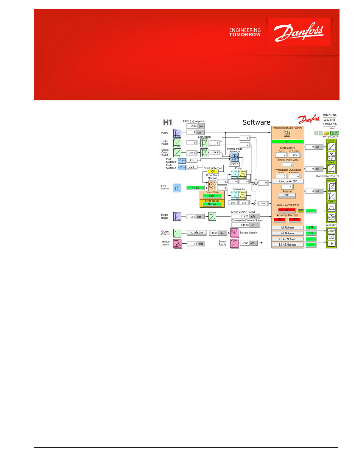
The Automotive Control (AC) is an electric NFPE
control with an integrated micro-controller, installed
on the pump. The integrated micro-controller
enhances control performance with a flexible,
configurable control scheme for an entire single path
propel transmission. It can be used in combination
with fixed and variable displacement hydraulic
motors. The propel system can be used with
mechanical controlled or CAN controlled engines.
With the pre-installed application software and easily
changeable control parameters, it is possible to tailor
the vehicle‘s driving behavior to the individual
requirements of the customer. Target applications
with a load dependent driving behavior:
•
Wheel loader, telehandler, dumper (torque
controlled)
•
Sweeper, snow blower, forestry machines (speed
controlled)
Features
Basic functions
•
Four system modes, selectable by the
driver for different drive behaviour
•
Independent pump/motor profiling and
ramping for each system mode
•
Electric drive pedal
•
Electric inching
•
Electric creep mode potentiometer
•
Hand throttle for engine speed control
•
Reversing in all possible driving
conditions
•
Load dependent pump displacement
control (automotive)
•
Load independent pump displacement
control with integrated swash-plate
angle sensor (optional)
•
Two position and proportional motor
displacement control
•
System status (errors) by LED
Protection and safety functions
•
Safety controlled vehicle start
protection
•
Operator presence detection
•
Hydraulic system overheat and low
temperature protection
•
Hydraulic motor overspeed protection
•
Safety functions according EN1459,
ISO20474, ISO 25119 and ISO 13849 up
to performance level d
Engine control and protection
•
CAN J1939 and Kubota engine protocol
•
Engine speed control via drive pedal or
hand throttle with safety controlled
monitoring function
•
Engine over speed and cold start
protection
•
Engine anti-stall and speed-dependent
retarder control
Performance functions
•
ECO fuel saving mode
•
Cruise control in work mode
•
Vehicle constant speed control by drive
pedal
•
Vehicle speed limitation
•
Digital outputs for:
dynamic brake light
‒
automatic park brake
‒
reverse buzzer
‒
vehicle speed controlled output
‒
functions
•
Temperature compensation for
predictable performance
•
Advanced CAN J1939 interface
©
Danfoss | February 2019 AI289060682770en-000101 | 1
Page 2
AC controller
Specifications
Controller
Rated supply voltage 12 V system 9 – 16 V
Rated supply voltage 24 V system 18 – 36 V
Digital and PWM outputs 3000 mA
Sensor supply (internal) 5 V / 1 A
Ambient temperature -40 to 104°C
IP rating with attached connectors IP69k
EMC immunity 100 V/m
Vibration and shock tested IEC 60068
Comprehensive technical literature is online at www.danfoss.com
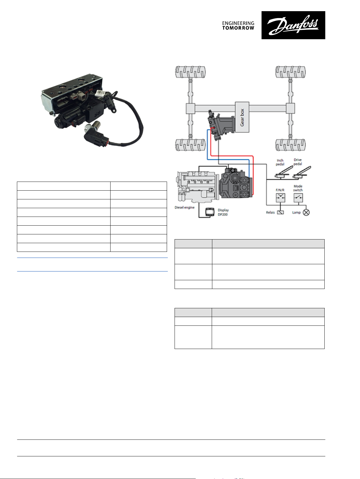
Telehandler system schematic
Input configuration
Input Function
6 x digital FNR (direction selection), seat switch, system mode
switches
7 x analog Inch pedal, drive pedal, creep potentiometer, hand
throttle, engine speed set-up point, pressure sensors
2 x frequency Pump/engine, hydro-motor rpm
Output configuration
Output Function
3 x PWM Pump and hydro-motor displacement control
5 x digital Hydraulic motor brake pressure defeat, dynamic brake
light, hand brake, reverse buzzer, retarder control,
vehicle speed dependent output, status LED
Danfoss can accept no responsibility for possible errors in catalogues, brochures and other printed material. Danfoss reserves the right to alter its products without notice. This also applies to products
already on order provided that such alterations can be made without subsequent changes being necessary in specifications already agreed.
All trademarks in this material are property of the respective companies. Danfoss and the Danfoss logotype are trademarks of Danfoss A/S. All rights reserved.
2 | © Danfoss | February 2019 AI289060682770en-000101
 Loading...