

Page 1
User Manual
PLUS+1® GUIDE Software
PLUS+1 Function Block Library—Input
Function Blocks
www.danfoss.com
Page 2

User Manual
PLUS+1® Compliant Function Block Library—Input Function Blocks
Revision history Table of revisions
Date Changed Rev
February 2019 Updated calibration and deadband images 0102
February 2019 Rebranding 0101
May 2016 Updates for new library version. CA
March 2011 AB
2 | © Danfoss | February 2019 11062082 | AQ00000274en-000102
Page 3

User Manual
PLUS+1® Compliant Function Block Library—Input Function Blocks
Contents
Risk Reduction
Design, Test, and Secure to Reduce Risks................................................................................................................................5
Design...................................................................................................................................................................................................5
Test.........................................................................................................................................................................................................5
Secure................................................................................................................................................................................................... 6
FNR_Direction Function Block
Inputs....................................................................................................................................................................................................7
Outputs................................................................................................................................................................................................ 7
Function Block Connections.........................................................................................................................................................9
Fault Logic...........................................................................................................................................................................................9
Identical Function Blocks Need Different Namespace Values to Successfully Compile.........................................9
Change Namespace Value.....................................................................................................................................................10
IEC 61508-3 Annex D Supplemental Information.............................................................................................................. 11
Multi_Dig_In Function Block
Inputs..................................................................................................................................................................................................12
Outputs..............................................................................................................................................................................................13
Function Block Connections...................................................................................................................................................... 14
Status Logic......................................................................................................................................................................................15
Fault Logic........................................................................................................................................................................................ 15
Example 1—Slct is T......................................................................................................................................................................15
Example 2—Slct is F......................................................................................................................................................................16
Identical Function Blocks Need Different Namespace Values to Successfully Compile...................................... 16
Change Namespace Value.....................................................................................................................................................17
IEC 61508-3 Annex D Supplemental Information.............................................................................................................. 18
Sensor_2Pt Function Block
Inputs..................................................................................................................................................................................................19
Outputs..............................................................................................................................................................................................20
Function Block Connections...................................................................................................................................................... 21
Status Logic......................................................................................................................................................................................22
Fault Logic........................................................................................................................................................................................ 22
Calibration and Fault Values...................................................................................................................................................... 22
Deadband Values...........................................................................................................................................................................23
Identical Function Blocks Need Different Namespace Values to Successfully Compile...................................... 24
Change Namespace Value.....................................................................................................................................................25
IEC 61508-3 Annex D Supplemental Information.............................................................................................................. 26
Sensor_3Pt Function Block
Inputs..................................................................................................................................................................................................27
Outputs..............................................................................................................................................................................................28
Function Block Connections...................................................................................................................................................... 29
Status Logic......................................................................................................................................................................................30
Fault Logic........................................................................................................................................................................................ 30
Calibration and Fault Values...................................................................................................................................................... 30
Deadband Values...........................................................................................................................................................................31
Identical Function Blocks Need Different Namespace Values to Successfully Compile...................................... 32
Change Namespace Value.....................................................................................................................................................33
IEC 61508-3 Annex D Supplemental Information.............................................................................................................. 34
Sensor_2Pt_AC Function Block
Inputs..................................................................................................................................................................................................35
Outputs..............................................................................................................................................................................................36
Configuration Settings.................................................................................................................................................................36
Function Block Connections...................................................................................................................................................... 38
Status Logic......................................................................................................................................................................................39
Fault Logic........................................................................................................................................................................................ 39
Calibration and Fault Values...................................................................................................................................................... 39
Deadband Values...........................................................................................................................................................................40
Calibration Windows.................................................................................................................................................................... 41
©
Danfoss | February 2019 11062082 | AQ00000274en-000102 | 3
Page 4

User Manual
PLUS+1® Compliant Function Block Library—Input Function Blocks
Contents
Identical Function Blocks Need Different Namespace Values to Successfully Compile...................................... 42
Change Namespace Value.....................................................................................................................................................43
IEC 61508-3 Annex D Supplemental Information.............................................................................................................. 44
Sensor_3Pt_AC Function Block
Inputs..................................................................................................................................................................................................45
Outputs..............................................................................................................................................................................................46
Configuration Settings.................................................................................................................................................................46
Function Block Connections...................................................................................................................................................... 48
Status Logic......................................................................................................................................................................................49
Fault Logic........................................................................................................................................................................................ 49
Calibration and Fault Values...................................................................................................................................................... 49
Deadband Values...........................................................................................................................................................................50
Calibration Windows.................................................................................................................................................................... 51
Identical Function Blocks Need Different Namespace Values to Successfully Compile...................................... 52
Change Namespace Value.....................................................................................................................................................53
IEC 61508-3 Annex D Supplemental Information.............................................................................................................. 54
Freq_to_RPM Function Block
Inputs..................................................................................................................................................................................................55
Outputs..............................................................................................................................................................................................55
Function Block Connections...................................................................................................................................................... 56
Status Logic......................................................................................................................................................................................56
Fault Logic........................................................................................................................................................................................ 56
Identical Function Blocks Need Different Namespace Values to Successfully Compile...................................... 57
Change Namespace Value.....................................................................................................................................................57
IEC 61508-3 Annex D Supplemental Information.............................................................................................................. 58
Freq_to_Speed Function Block
Inputs..................................................................................................................................................................................................59
Outputs..............................................................................................................................................................................................59
Function Block Connections...................................................................................................................................................... 61
Status Logic......................................................................................................................................................................................61
Fault Logic........................................................................................................................................................................................ 62
Identical Function Blocks Need Different Namespace Values to Successfully Compile...................................... 62
Change Namespace Value.....................................................................................................................................................62
IEC 61508-3 Annex D Supplemental Information.............................................................................................................. 64
4 | © Danfoss | February 2019 11062082 | AQ00000274en-000102
Page 5

User Manual
PLUS+1® Compliant Function Block Library—Input Function Blocks
Risk Reduction
Design, test, and secure applications that you develop to reduce risks of personal injury and equipment
damage.
Design, Test, and Secure to Reduce Risks
Applications created with PLUS+1® GUIDE typically control equipment such as tractors, cranes, and
harvesters.
Using heavy, powerful, and mobile off-road equipment always involves the risk of personal injury and
equipment damage, even when this equipment is operating under normal operating conditions.
Abnormal operating conditions greatly increase the risk of personal injury and equipment damage.
The PLUS+1® program has no automatic protections against these risks. The tool has no protection
against the risks that result from bugs in the tool software, errors in the tool manual, or incompatibilities
between software versions of the tool.
You must:
•
Design your application to reduce these risks.
•
Test your application to reduce these risks.
•
Secure your application against unauthorized changes in its operating parameters to reduce these
risks.
Design
Test
As you design your application, you must include the fault checking and the error handling needed to
reduce risks in normal and abnormal operating conditions.
Consider the following when developing fault checking and error handling for your PLUS+1® GUIDE
application:
•
How the machine is normally used.
•
Possible operator errors and their consequences.
•
Industry safety standards and legal requirements.
•
Input and output failures and their consequences. These failures can include:
Joystick, sensor, and other inputs suddenly going to ±100 % or to 0 %.
‒
Joystick, sensor, and other inputs suddenly going to ±100 % or to 0 %.
‒
Outputs that control machinery direction, speed, and force suddenly changing direction or going
‒
to ±100 % or to 0 %.
Decide how likely each failure is. The more likely a failure, the more you need to protect against
the consequences of the failure.
•
The sequence of events and consequences of a fault or error.
•
The sequence of events and consequences of an emergency stop.
After creating an application, you are responsible for testing the application.
Download your application to hardware and test its operation under both normal and abnormal
operating conditions. Make sure:
•
Individual inputs produce expected outputs.
•
Fault handling and error checking work as designed.
You must repeat your tests when you make configuration, calibration, or software changes to the
application.
©
Danfoss | February 2019 11062082 | AQ00000274en-000102 | 5
Page 6

User Manual
PLUS+1® Compliant Function Block Library—Input Function Blocks
Risk Reduction
Secure
You have the responsibility to secure your application against unauthorized changes.
Always use the PLUS+1® GUIDE program’s Toolkey feature to restrict access to your application’s
operating parameters.
•
Without Toolkey protection, there is an increased risk that unauthorized personnel could use the
PLUS+1® Service Tool program to change your application’s operating parameters.
Changes in your application’s operating parameters might cause unexpected machinery movement
that results in personal injury and equipment damage.
•
Toolkey protection reduces the risk that unauthorized personnel could use the PLUS+1® program to
change your application’s operating parameters.
Refer to How to Use the Toolkey to Restrict Service Tool Access to Application Values in the PLUS+1—How-to
chapter of the PLUS+1 GUIDE User Manual (Danfoss part 10100824).
6 | © Danfoss | February 2019 11062082 | AQ00000274en-000102
Page 7
User Manual
PLUS+1® Compliant Function Block Library—Input Function Blocks
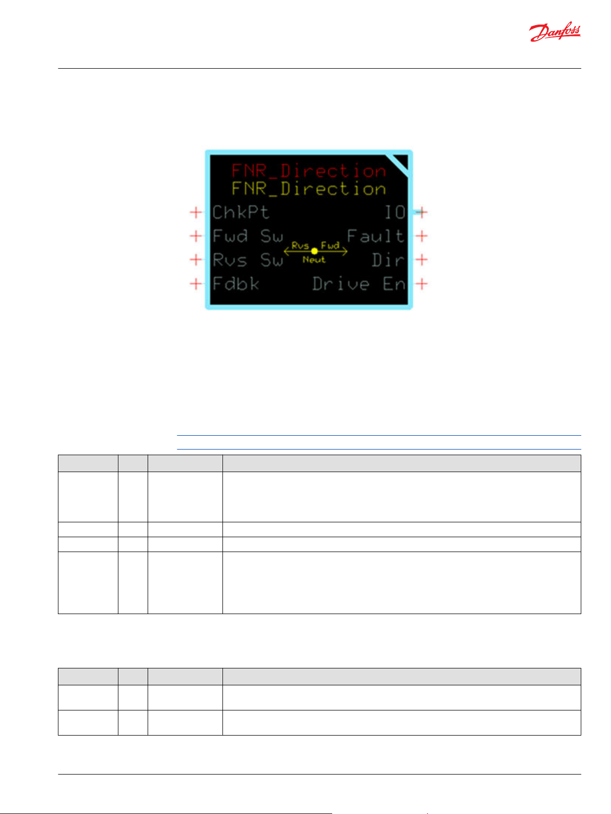
FNR_Direction Function Block
The FNR_Direction block provides interlock logic to prevent output commands when changing
directions before coming to a complete stop.
Typical uses include:
•
Protecting hardware on machines from damage caused by abrupt changes in direction under heavy
load.
•
Detecting faults on directional switches.
Inputs
The inputs to the FNR_Direction function block are described.
Use only the data types specified in this table. Other data types cause compiler errors.
Item Type Range Description
ChkPt BOOL ——
Fwd Sw BOOL —— Forward switch—input signal indicating that the desired direction is forward.
Rvs Sw BOOL —— Reverse switch—input signal indicating that the desired direction is reverse.
Fdbk S32 -2147483648–
2147483647
True—include the function block’s built-in Advanced Checkpoint with Namespace in the compiled
•
LHX download file.
False—exclude the function block’s built-in Advanced Checkpoint with Namespace components
•
from the compiled LHX download file.
Feedback—input signal indicating the actual direction of movement. The magnitude of the signal is
not used.
•
Fdbk < 0—reverse
•
Fdbk = 0—neutral
•
Fdbk > 0—forward
Outputs
The outputs of the FNR_Direction function block are described.
Item Type Range Description
IO Bus —— Outputs a bus with all of the function block's input and output signals.
This bus provides a convenient way to distribute this function block's signals to your application.
Fault U16 —— Reports the faults of the function block.
This output follows the standard bitwise scheme described in the Status Logic topic.
©
Danfoss | February 2019 11062082 | AQ00000274en-000102 | 7
Page 8

User Manual
PLUS+1® Compliant Function Block Library—Input Function Blocks
FNR_Direction Function Block
Item Type Range Description
Dir S16 -1–1 Current output direction. This value is only allowed to change if the Fdbk= 0 or its value is the same
sign as the desired direction.
•
-1 = Reverse
•
0 = Neutral
•
1 = Forward
Drv Enbl BOOL —— Drive enable—this signal can be used to provide an interlock for an application’s propel command or
work function.
8 | © Danfoss | February 2019 11062082 | AQ00000274en-000102
Page 9
User Manual
PLUS+1® Compliant Function Block Library—Input Function Blocks
FNR_Direction Function Block
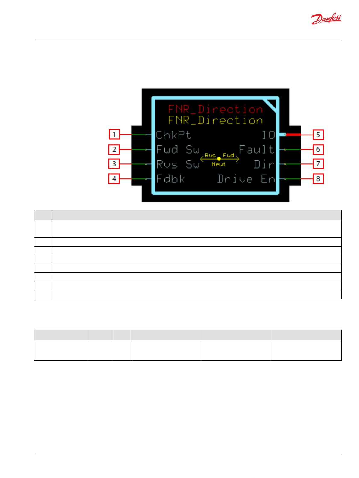
Function Block Connections
Connections you can make with the function block are described.
Description
Item
1
2 Forward Switch Input
3 Reverse Switch Input
4 Signed feedback signal from speed sensor, indicating direction.
5 Outputs a bus with all of the function block's input and output signals.
6 Reports the faults of the function block.
7 Output direction command.
8 Drive enable signal to be used as part of an application propel or work function interlock.
True—include the function block’s built-in Advanced Checkpoint with Namespace in the compiled LHX download file.
•
False—exclude the function block’s built-in Advanced Checkpoint with Namespace components from the compiled LHX download file.
•
Fault Logic
This topic describes how fault logic is indicated for the function block.
Condition Hex
Invalid input
combination
*
Bit 16 set to 1 identifies a standard Danfoss status or fault code.
*
Binary Cause Response Correction
0x8040 01000
000
Both Fwd Sw and Rvs Sw are
true at the same time.
Drive En = False
•
Dir = 0
•
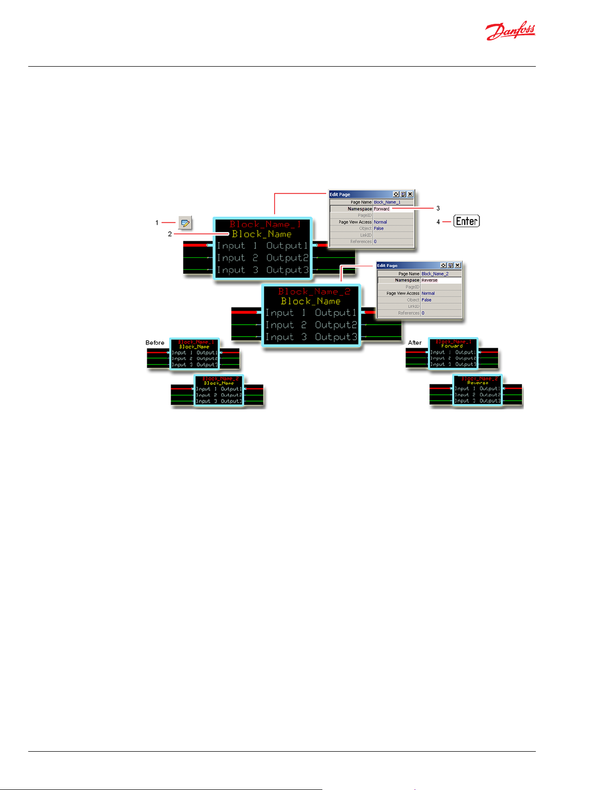
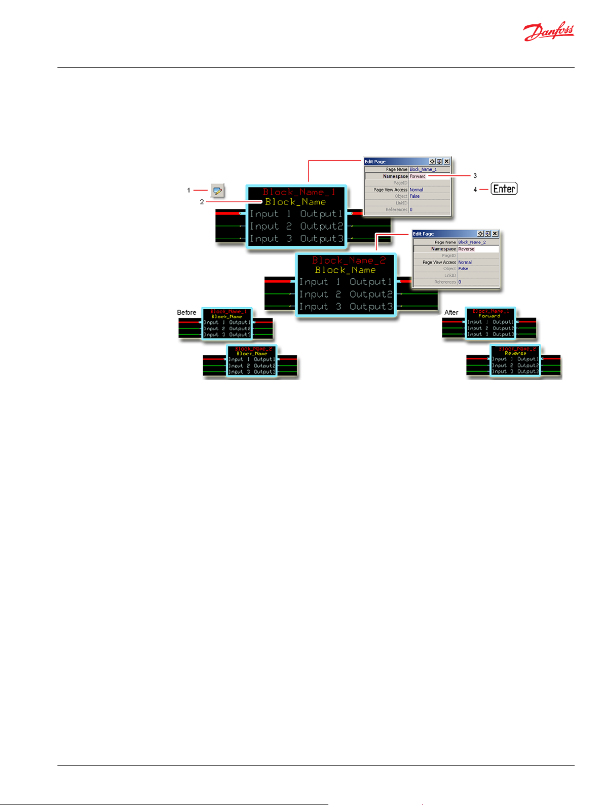
Identical Function Blocks Need Different Namespace Values to Successfully Compile
If you use the same function block more than once in an application, you must change each function
block’s namespace value to avoid compiler errors.
All function blocks contain Advanced Checkpoint with Namespace components that enable the PLUS+1
Service Tool to read block input and output values.
Some function blocks contain non-volatile memory components that store function block operating
parameters.
Both these components use memory names (“aliases”) to allocate memory. Identical memory names
cause compiler errors.
Ensure system design only allows
at most one direction input to be
true at any time.
®
©
Danfoss | February 2019 11062082 | AQ00000274en-000102 | 9
Page 10
User Manual
PLUS+1® Compliant Function Block Library—Input Function Blocks
FNR_Direction Function Block
The namespace value adds a unique prefix to each component name to avoid errors. Keep each
namespace value short to save controller memory.
Change Namespace Value
To successfully compile your application, change the namespace value for function blocks that are used
more than once in an application.
1. In the PLUS+1® GUIDE menu bar, click the Query/Change button.
2. Click on the function block whose namespace you want to set to a unique value.
The Edit Page window opens.
3. In the Edit Page window, enter a meaningful Namespace value.
Namespace values are case-sensitive.
•
To save controller memory, use a short namespace value.
•
4. Press Enter.
5. Repeat these steps to enter unique namespace values for other identical function blocks.
10 | © Danfoss | February 2019 11062082 | AQ00000274en-000102
Page 11

User Manual
PLUS+1® Compliant Function Block Library—Input Function Blocks
FNR_Direction Function Block
IEC 61508-3 Annex D Supplemental Information
The following table provides IEC 61508-3 Annex D supplemental information.
Item
Function block name FNR_Direction
Function block version 4.0.
Function block development
environment
Compatible hardware
Function block developed in
compliance with
Competence required of
function block integrator
Contacting Danfoss
Description
PLUS+1® GUIDE version 8.1 and later.
Verified in the PLUS+1® GUIDE compile process.
When the PLUS+1® GUIDE compiler finds a function block that is incompatible with hardware, it aborts the compile
process and logs an error message. The error message gives the location of the function block and states “Error 80:
component not supported in hwd.”
Danfoss Software Product Development Process (PDP), which includes ISO 9001 and IEC 61508-3 standards.
The knowledge, competence, and training required to:
Understand this manual.
•
Use the PLUS+1® GUIDE program to develop a machine control application.
•
Follow quality software practices to develop a machine control application.
•
https://www.danfoss.com/en/products/software/dps/plus1-software-services-support-and-training/plus1-support-andservices
©
Danfoss | February 2019 11062082 | AQ00000274en-000102 | 11
Page 12
User Manual
PLUS+1® Compliant Function Block Library—Input Function Blocks
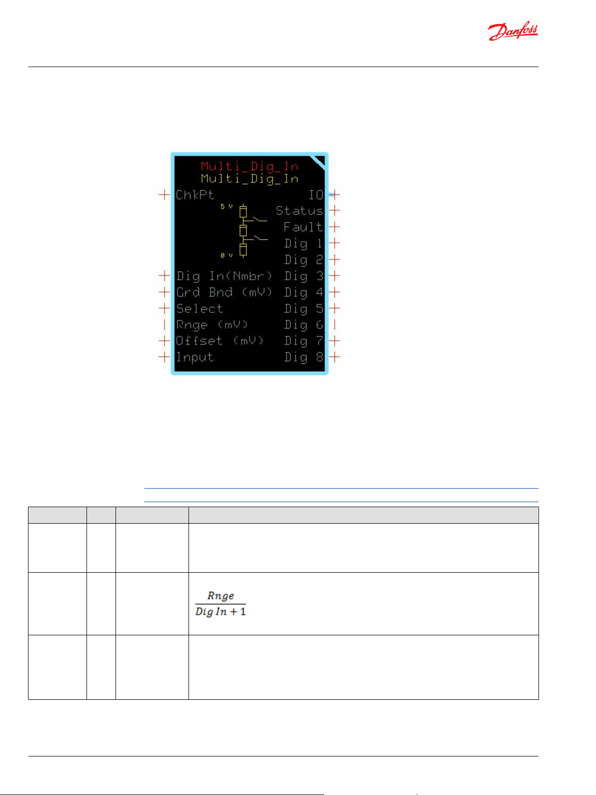
Multi_Dig_In Function Block
The Multi_Dig_In block converts an analog voltage signal applied to its Input into several Dig output
signals.
Typical uses for this function block include:
Reading the status of a multi-position sensor switch.
•
Reading the position of HMI switches on a dashboard control.
•
Inputs
The inputs to the Multi_Dig_In function block are described.
Use only the data types specified in this table. Other data types cause compiler errors.
Item Type Range Description
ChkPt BOOL ——
Dig In (Nmbr) U8 1–8 Sets the number of active Dig outputs and the activation point for each Dig output.
Grd Bnd (mV) U16 0–Rnge/(1+Dig In) When Slct (Select) is T ,the Grd Bnd (Guard Band) value sets the width of a guard band that centers on
True—include the function block’s built-in Advanced Checkpoint with Namespace in the compiled
•
LHX download file.
False—exclude the function block’s built-in Advanced Checkpoint with Namespace components
•
from the compiled LHX download file.
determines the interval between Dig output activation points.
The block distributes activation points evenly across the Range.
the activation point for each Dig output.
1000 = 1000 (no scaling applied)
When Slct is F, the Grd Bnd value sets the width of a guard band that extends above the activation
point for each Dig output.
1000 = 100 (10.00% scaling applied)
12 | © Danfoss | February 2019 11062082 | AQ00000274en-000102
Page 13

User Manual
PLUS+1® Compliant Function Block Library—Input Function Blocks
Multi_Dig_In Function Block
Item Type Range Description
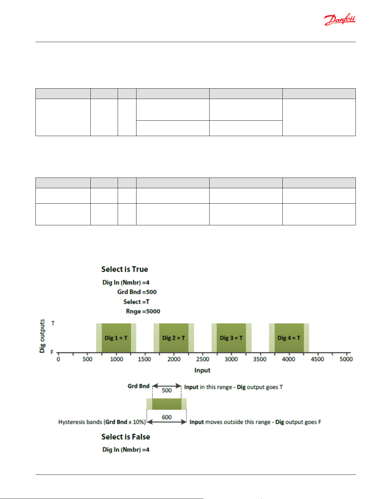
Select BOOL —— When Select is T, the block enables just one Dig output at a time.
An Input signal in the guard band of a Dig output sets its output T. A T output adds hysteresis bands to
both sides of the output’s guard band. (Each hysteresis band is equal to 10% of the guard band’s
width.)
A T Dig output goes F when the Input signal moves outside of the hysteresis bands.
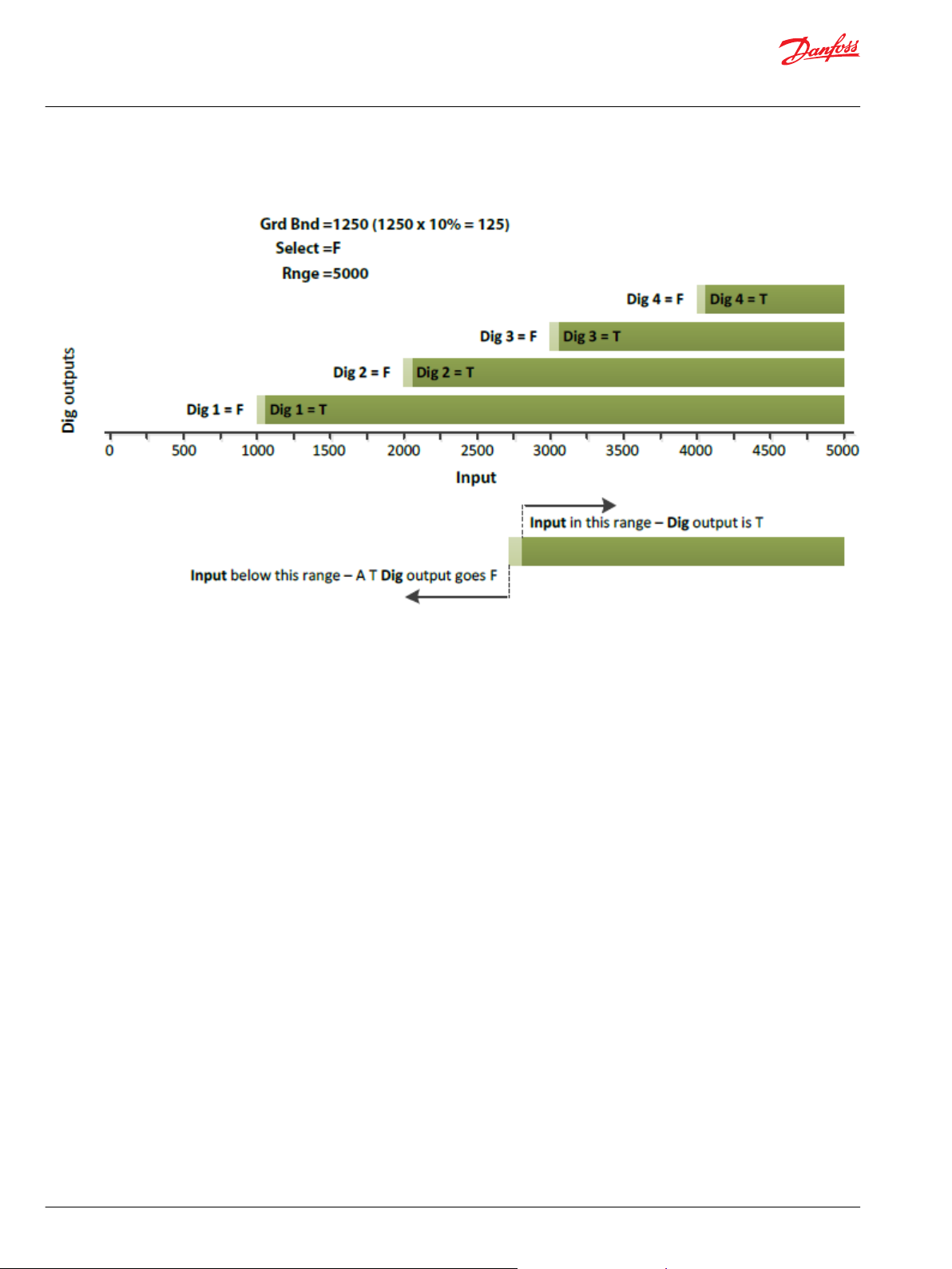
When Select is F, the block sequentially enables Digoutputs.
An Inputsignal above the guard band of a Dig output sets its output T. A T Dig output goes F when the
Input signal drops below its guard band.
Rnge (mV) U16 0–40000 Range of Input over which the block operates.
Offset (mV) U16 0–40000 Adjusts the center voltage calculation for each activation point. The Offset value moves each range up
by that amount.
10 = 10 mV
Input U16 0 to (Rnge +
Offset)
Outputs
The outputs of the Multi_Dig_In function block are described.
Signal from the sensor or HMI device. Changes in this input’s value switch the Dig outputs between T
and F.
10 = 10 mV
Item Type Range Description
IO Bus —— Outputs a bus with all of the function block's input and output signals.
This bus provides a convenient way to distribute this function block's signals to your application.
Status U16 —— Reports the status of the function block.
This output follows the standard bitwise scheme described in the Status Logic topic.
Fault U16 —— Reports the faults of the function block.
This output follows the standard bitwise scheme described in the Status Logic topic.
Dig 1 BOOL ——
Dig 2 BOOL ——
Dig 3 BOOL ——
Dig 4 BOOL ——
Dig 5 BOOL ——
Dig 6 BOOL ——
Dig 7 BOOL ——
Dig 8 BOOL ——
Interpreted input state for the lowest digital range.
Interpreted input state for digital range 2.
Interpreted input state for digital range 3.
Interpreted input state for digital range 4.
Interpreted input state for digital range 5.
Interpreted input state for digital range 6.
Interpreted input state for digital range 7.
Interpreted input state for digital range 8.
©
Danfoss | February 2019 11062082 | AQ00000274en-000102 | 13
Page 14
User Manual
PLUS+1® Compliant Function Block Library—Input Function Blocks
Multi_Dig_In Function Block
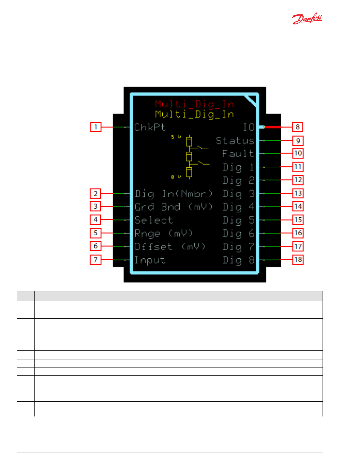
Function Block Connections
Connections you can make with the function block are described.
Description
Item
1
2 Number of digital inputs to be interpreted.
3 Sets the range around or above each switch point.
4 Sets the input mode type. When true, only one Dig output is true at a time. When false, all Dig outputs at or below the Input switch point are
5 Indicates the expected range of Input from the lowest to highest switch point.
6 Indicates the shift of the Input signal above 0.
7 Signal from the sensor representing digital input states.
8 Outputs a bus with all of the function block's input and output signals.
9 Reports the status of the function block.
10 Reports the faults of the function block.
11to18Digital input states interpreted from the Input.
True—include the function block’s built-in Advanced Checkpoint with Namespace in the compiled LHX download file.
•
False—exclude the function block’s built-in Advanced Checkpoint with Namespace components from the compiled LHX download file.
•
true..
14 | © Danfoss | February 2019 11062082 | AQ00000274en-000102
Page 15
User Manual
PLUS+1® Compliant Function Block Library—Input Function Blocks
Multi_Dig_In Function Block
Status Logic
This topic describes how status logic is indicated for the function block.
Condition Hex
Invalid configuration 0x8008 1000
*
Bit 16 set to 1 identifies a standard Danfoss status or fault code.
Fault Logic
Condition Hex
Input value is too low. 0x8001 0001 Input value below zero. Output signals are based on
Input value is too high. 0x8002 0010 Input value above (Rnge +
*
Bit 16 set to 1 identifies a standard Danfoss status or fault code.
*
Binary Cause Response Correction
Dig In, Grd Bnd, Rnge and/or
Offset parameters out of range
The Grd Bnd is larger than the
calculated digital interval size.
Output signal is calculated using
the parameters clamped to their
respective ranges.
The Grd Bnd is limited to the
calculated digital interval size.
This topic describes how fault logic is indicated for the function block.
*
Binary Cause Response Correction
Input = 0.
Offset).
Output signals are based on
Input = (Rnge + Offset).
Review function inputs to ensure
they are within their valid
ranges..
Ensure Input is within the valid
range.
Ensure Input is within the valid
range. Ensure Rnge and Offset
are correct.
Example 1—Slct is T
©
Danfoss | February 2019 11062082 | AQ00000274en-000102 | 15
Page 16
User Manual
PLUS+1® Compliant Function Block Library—Input Function Blocks
Multi_Dig_In Function Block
Example 2—Slct is F
Identical Function Blocks Need Different Namespace Values to Successfully Compile
If you use the same function block more than once in an application, you must change each function
block’s namespace value to avoid compiler errors.
All function blocks contain Advanced Checkpoint with Namespace components that enable the PLUS+1
Service Tool to read block input and output values.
Some function blocks contain non-volatile memory components that store function block operating
parameters.
Both these components use memory names (“aliases”) to allocate memory. Identical memory names
cause compiler errors.
The namespace value adds a unique prefix to each component name to avoid errors. Keep each
namespace value short to save controller memory.
®
16 | © Danfoss | February 2019 11062082 | AQ00000274en-000102
Page 17
User Manual
PLUS+1® Compliant Function Block Library—Input Function Blocks
Multi_Dig_In Function Block
Change Namespace Value
To successfully compile your application, change the namespace value for function blocks that are used
more than once in an application.
1. In the PLUS+1® GUIDE menu bar, click the Query/Change button.
2. Click on the function block whose namespace you want to set to a unique value.
The Edit Page window opens.
3. In the Edit Page window, enter a meaningful Namespace value.
Namespace values are case-sensitive.
•
To save controller memory, use a short namespace value.
•
4. Press Enter.
5. Repeat these steps to enter unique namespace values for other identical function blocks.
©
Danfoss | February 2019 11062082 | AQ00000274en-000102 | 17
Page 18

User Manual
PLUS+1® Compliant Function Block Library—Input Function Blocks
Multi_Dig_In Function Block
IEC 61508-3 Annex D Supplemental Information
The following table provides IEC 61508-3 Annex D supplemental information.
Item
Function block name Multi_Dig_In.
Function block version 4.0.
Function block development
environment
Compatible hardware
Function block developed in
compliance with
Competence required of
function block integrator
Contacting Danfoss
Description
PLUS+1® GUIDE version 8.1 and later.
Verified in the PLUS+1® GUIDE compile process.
When the PLUS+1® GUIDE compiler finds a function block that is incompatible with hardware, it aborts the compile
process and logs an error message. The error message gives the location of the function block and states “Error 80:
component not supported in hwd.”
Danfoss Software Product Development Process (PDP), which includes ISO 9001 and IEC 61508-3 standards.
The knowledge, competence, and training required to:
Understand this manual.
•
Use the PLUS+1® GUIDE program to develop a machine control application.
•
Follow quality software practices to develop a machine control application.
•
https://www.danfoss.com/en/products/software/dps/plus1-software-services-support-and-training/plus1-support-andservices
18 | © Danfoss | February 2019 11062082 | AQ00000274en-000102
Page 19
User Manual
PLUS+1® Compliant Function Block Library—Input Function Blocks
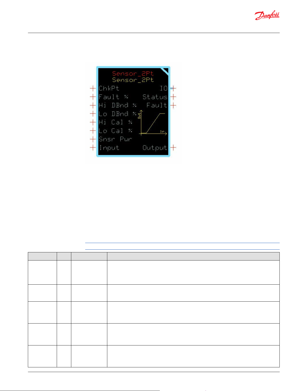
Sensor_2Pt Function Block
The Sensor_2Pt block converts a raw signal from a sensor into a percentage output.
The percentage output is based on the signal characteristics of the sensor. This block scales its Output
between 0% and +100%.
Typical uses for this function block include:
Reading analog sensors where piece–to-piece variation is negligible for the required accuracy of the
•
signal.
Implementing an alternative sensor calibration algorithm and using this block for the scaling and
•
fault detection functions.
Reading max speed potentiometers, trim steer potentiometers, and fuel level sensors.
•
Inputs
The inputs to the Sensor_2Pt function block are described.
Use only the data types specified in this table. Other data types cause compiler errors.
Item Type Range Description
ChkPt BOOL ——
Fault % U16 0–10000 The Input is allowed to go above the Hi Cal % and below the Lo Cal % by a calculated allowable fault
Hi DBnd % U16 0–5000 Hi DBnd % (High Deadband Percent) defines the deadband region for the sensor’s upper limit.
Lo DBnd % U16 0–5000 Lo DBnd % (Low Deadband Percent) defines the deadband region for the sensor’s lower limit.
Hi Cal % U16 0–10000 Hi Cal % (High Calibration Percent) defines the upper limit of the sensor’s signal in terms of the sensor’s
True—include the function block’s built-in Advanced Checkpoint with Namespace in the compiled
•
LHX download file.
False—exclude the function block’s built-in Advanced Checkpoint with Namespace components
•
from the compiled LHX download file.
value. The fault value is the Fault % of the calibrated input range.
1000 = 10.00%
Increasing the deadband value decreases the sensor’s resolution while reducing the deadband narrows
the margin for acceptable input noise and sensor variation.
1000 = 10.00%
Increasing the deadband value decreases the sensor’s resolution while reducing the deadband narrows
the margin for acceptable input noise and sensor variation.
1000 = 10.00%
supply voltage.
This is a percentage of Snsr Pwr.
1000 = 10.00%
©
Danfoss | February 2019 11062082 | AQ00000274en-000102 | 19
Page 20
User Manual
PLUS+1® Compliant Function Block Library—Input Function Blocks
Sensor_2Pt Function Block
Item Type Range Description
Lo Cal % U16 0–10000 Lo Cal % (Low Calibration Percent) defines the lower limit of the sensor’s signal in terms of the sensor’s
supply voltage.
This is a percentage of Snsr Pwr.
1000 = 10.00%
Snsr Pwr U16 0–65535 Snsr Pwr (Sensor Power) defines the reference for ratiometric calculations. If a sensor is ratiometric, the
function block’s Output signal is continually compensated for variation in the supply. If the sensor is
not ratiometric, connect a constant value representing the full scale signal range.
Input U16 0–65535 Signal from the sensor. The units of this signal must be the same units for Snsr Pwr.
Outputs
The outputs of the Sensor_2Pt function block are described.
Item Type Range Description
IO Bus —— Outputs a bus with all of the function block's input and output signals.
This bus provides a convenient way to distribute this function block's signals to your application.
Status U16 —— Reports the status of the function block.
This output follows the standard bitwise scheme described in the Status Logic topic.
Fault U16 —— Reports the faults of the function block.
This output follows the standard bitwise scheme described in the Status Logic topic.
Output U16 0–10000 Percent of Input applied to the sensor’s calibrated range.
1000 = 10.00%
20 | © Danfoss | February 2019 11062082 | AQ00000274en-000102
Page 21
User Manual
PLUS+1® Compliant Function Block Library—Input Function Blocks
Sensor_2Pt Function Block
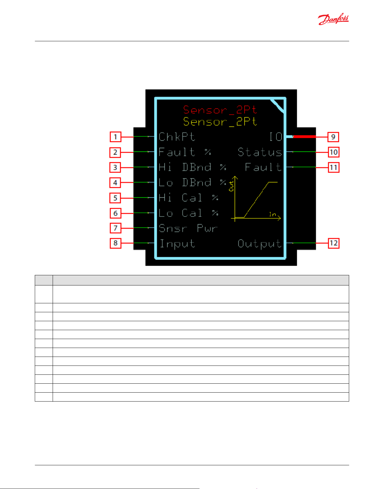
Function Block Connections
Connections you can make with the function block are described.
Description
Item
1
2 Deviation below and above the calibration point allowed before reporting an input fault condition.
3 Defines the size of the deadband region at the high calibration point. Within this region the output is 10000 (100%).
4 Defines the size of the deadband region at the low calibration point. Within this region the output is 0 (0%).
5 Sets the high end of the sensor’s nominal Input signal range as a percent of Snsr Pwr.
6 Sets the low end of the sensor’s nominal Input signal range as a percent of Snsr Pwr.
7 Used to monitor the sensor’s power supply to make ratiometric adjustments within the function block.
8 Signal indicating the position of the sensor.
9 Outputs a bus with all of the function block's input and output signals.
10 Reports the status of the function block.
11 Reports the faults of the function block.
12 Position indicator of the sensor as a percent of its calibration range.
True—include the function block’s built-in Advanced Checkpoint with Namespace in the compiled LHX download file.
•
False—exclude the function block’s built-in Advanced Checkpoint with Namespace components from the compiled LHX download file.
•
©
Danfoss | February 2019 11062082 | AQ00000274en-000102 | 21
Page 22

User Manual
PLUS+1® Compliant Function Block Library—Input Function Blocks
Sensor_2Pt Function Block
Status Logic
This topic describes how status logic is indicated for the function block.
Condition Hex
Invalid configuration 0x8008 1000 Fault %, Hi DBnd %, Lo DBnd
*
Bit 16 set to 1 identifies a standard Danfoss status or fault code.
Fault Logic
Condition Hex
Input value is too low. 0x8001 0001 Input value below Fault %
Input value is too high. 0x8002 0010 Input value above Fault %
*
Bit 16 set to 1 identifies a standard Danfoss status or fault code.
*
Binary Cause Response Correction
Output signal is calculated using
%, Hi Cal %, Lo Cal %
parameters and/or Snsr Pwr is
outside its defined range.
the parameters clamped to their
respective ranges.
This topic describes how fault logic is indicated for the function block.
*
Binary Cause Response Correction
Output = 0 Ensure Input is within the valid
region below Lo Cal %.
Output = 10000 Ensure Input is within the valid
region above Hi Cal %.
Review function inputs to ensure
they are within their valid ranges.
range. Ensure Fault % and Lo
Cal % are correct.
range. Ensure Fault % and Hi Cal
% are correct.
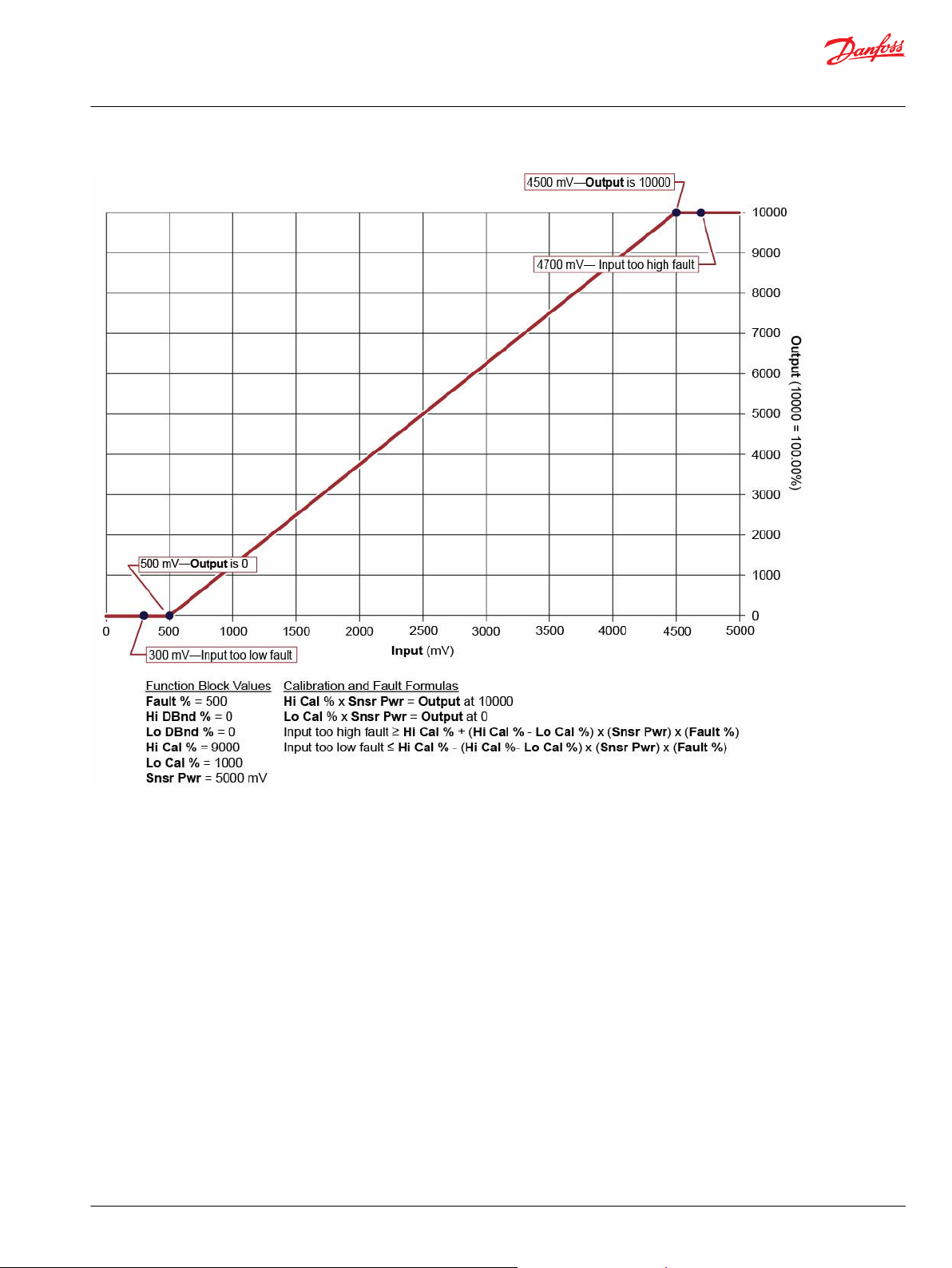
Calibration and Fault Values
This topic describes how out-of-range faults are defined, as well as how high, medium, and low
calibration output values are determined.
The following graph shows how the:
Hi Cal % input to the function block defines the Input value (in mV) that produces an Output value
•
of 10000.
Lo Cal % input to the function block defines the Input value (in mV) that produces an Output value
•
of 0.
Fault % input sets defines the Input values (in mV) at which the block declares out-of-range faults.
•
The function block has a Snsr Pwr input of 5000 mV.
22 | © Danfoss | February 2019 11062082 | AQ00000274en-000102
Page 23
User Manual
PLUS+1® Compliant Function Block Library—Input Function Blocks
Sensor_2Pt Function Block
Deadband Values
Inputs to the function block produce high, medium, and low deadband ranges.
The following graph shows how the:
Hi Dbnd % input to the function block sets a deadband range in which Inputvalues produce a
•
constant Outputvalue of 10000.
Lo Dbnd % input to the function block sets a deadband range in which Inputvalues produce a
•
constant Outputvalue of 0.
The function block has a Snsr Pwrinput of 5000 mV.
©
Danfoss | February 2019 11062082 | AQ00000274en-000102 | 23
Page 24

User Manual
PLUS+1® Compliant Function Block Library—Input Function Blocks
Sensor_2Pt Function Block
Identical Function Blocks Need Different Namespace Values to Successfully Compile
If you use the same function block more than once in an application, you must change each function
block’s namespace value to avoid compiler errors.
All function blocks contain Advanced Checkpoint with Namespace components that enable the PLUS+1
Service Tool to read block input and output values.
Some function blocks contain non-volatile memory components that store function block operating
parameters.
Both these components use memory names (“aliases”) to allocate memory. Identical memory names
cause compiler errors.
The namespace value adds a unique prefix to each component name to avoid errors. Keep each
namespace value short to save controller memory.
24 | © Danfoss | February 2019 11062082 | AQ00000274en-000102
®
Page 25

User Manual
PLUS+1® Compliant Function Block Library—Input Function Blocks
Sensor_2Pt Function Block
Change Namespace Value
To successfully compile your application, change the namespace value for function blocks that are used
more than once in an application.
1. In the PLUS+1® GUIDE menu bar, click the Query/Change button.
2. Click on the function block whose namespace you want to set to a unique value.
The Edit Page window opens.
3. In the Edit Page window, enter a meaningful Namespace value.
Namespace values are case-sensitive.
•
To save controller memory, use a short namespace value.
•
4. Press Enter.
5. Repeat these steps to enter unique namespace values for other identical function blocks.
©
Danfoss | February 2019 11062082 | AQ00000274en-000102 | 25
Page 26

User Manual
PLUS+1® Compliant Function Block Library—Input Function Blocks
Sensor_2Pt Function Block
IEC 61508-3 Annex D Supplemental Information
The following table provides IEC 61508-3 Annex D supplemental information.
Item
Function block name Sensor_2Pt
Function block version 4.0.
Function block development
environment
Compatible hardware
Function block developed in
compliance with
Competence required of
function block integrator
Contacting Danfoss
Description
PLUS+1® GUIDE version 8.1 and later.
Verified in the PLUS+1® GUIDE compile process.
When the PLUS+1® GUIDE compiler finds a function block that is incompatible with hardware, it aborts the compile
process and logs an error message. The error message gives the location of the function block and states “Error 80:
component not supported in hwd.”
Danfoss Software Product Development Process (PDP), which includes ISO 9001 and IEC 61508-3 standards.
The knowledge, competence, and training required to:
Understand this manual.
•
Use the PLUS+1® GUIDE program to develop a machine control application.
•
Follow quality software practices to develop a machine control application.
•
https://www.danfoss.com/en/products/software/dps/plus1-software-services-support-and-training/plus1-support-andservices
26 | © Danfoss | February 2019 11062082 | AQ00000274en-000102
Page 27

User Manual
PLUS+1® Compliant Function Block Library—Input Function Blocks
Sensor_3Pt Function Block
The Sensor_3Pt function block converts a raw signal from a sensor into a percentage output.
This percentage output is based on the signal characteristics of the sensor. This block scales its Output
between ±100%. Typical uses for this function block include:
Reading analog sensors where piece–to-piece variation is negligible for the required accuracy of the
•
signal.
Implementing an alternative sensor calibration algorithm and using this block for the scaling and
•
fault detection functions.
Reading bi-directional foot pedal, trim steer potentiometers, and joystick inputs.
•
Inputs
The inputs to the Sensor_3Pt function block are described.
Use only the data types specified in this table. Other data types cause compiler errors.
Item Type Range Description
ChkPt BOOL ——
Fault % U16 0–10000 The Input is allowed to go above the Hi Cal % and below the Lo Cal % by a calculated
Hi/Lo DBnd % U16 0–5000 Hi DBnd % (High/Low Deadband Percent) defines the deadband region for the sensor’s upper
Mid DBnd % U16 0–5000 Mid DBnd % (Middle Deadband Percent) defines the deadband region around the middle
Hi Cal % U16 0–10000 Hi Cal % (High Calibration Percent) defines the upper limit of the sensor’s signal in terms of
True—include the function block’s built-in Advanced Checkpoint with Namespace in the
•
compiled LHX download file.
False—exclude the function block’s built-in Advanced Checkpoint with Namespace
•
components from the compiled LHX download file.
allowable fault value. The fault value is the Fault % of the calibrated input range.
1000 = 10.00%
and lower limits.
Increasing the deadband value decreases the sensor’s resolution while reducing the deadband
narrows the margin for acceptable input noise and sensor variation.
1000 = 10.00%
calibration point.
Increasing the deadband value decreases the sensor’s resolution while reducing the deadband
narrows the margin for acceptable input noise and sensor variation.
1000 = 10.00%
the sensor’s supply voltage. When the Input is within the deadband around this calibration
value Output = 10000 (100.00%).
This is a percentage of Snsr Pwr.
1000 = 10.00%
©
Danfoss | February 2019 11062082 | AQ00000274en-000102 | 27
Page 28
User Manual
PLUS+1® Compliant Function Block Library—Input Function Blocks
Sensor_3Pt Function Block
Item Type Range Description
Mid Cal % U16 0–10000 Mid Cal % (Middle Calibration Percent) defines the middle point of the sensor’s signal in terms
of the sensor’s supply voltage. When the Input is within the deadband around this calibration
value Output = 0.
This is a percentage of Snsr Pwr.
1000 = 10.00%
Lo Cal % U16 0–10000 Lo Cal % (Low Calibration Percent) defines the lower limit of the sensor’s signal in terms of the
sensor’s supply voltage. When the Input is within the deadband around this calibration value
Output = -10000 (-100.00%).
This is a percentage of Snsr Pwr.
1000 = 10.00%
Snsr Pwr U16 0–65535 Snsr Pwr (Sensor Power) defines the reference for ratiometric calculations. If a sensor is
ratiometric, the function block’s Output signal is continually compensated for variation in the
supply. If the sensor is not ratiometric, connect a constant value representing the full scale
signal range.
Input U16 0–65535 Signal from the sensor. The units of this signal must be the same units for Snsr Pwr.
Outputs
The outputs of the Sensor_3pt function block are described.
Item Type Range Description
IO Bus —— Outputs a bus with all of the function block's input and output signals.
This bus provides a convenient way to distribute this function block's signals to your application.
Status U16 —— Reports the status of the function block.
This output follows the standard bitwise scheme described in the Status Logic topic.
Fault U16 —— Reports the faults of the function block.
This output follows the standard bitwise scheme described in the Status Logic topic.
Output S16 -10000–10000 Percent of Input applied to the sensor’s calibrated range.
1000 = 10.00%
28 | © Danfoss | February 2019 11062082 | AQ00000274en-000102
Page 29

User Manual
PLUS+1® Compliant Function Block Library—Input Function Blocks
Sensor_3Pt Function Block
Function Block Connections
Connections you can make with the function block are described.
Description
Item
1
2 Deviation below and above the calibration point allowed before reporting an input fault condition.
3 Defines the size of the deadband region at the high and low calibration points. Within the high region Output is 10000 (100%) and within the
4
5 Sets the high end of the sensor’s nominal Input signal range as a percent of Snsr Pwr.
6
7
8
9
10 Outputs a bus with all of the function block's input and output signals.
11 Reports the status of the function block.
12 Reports the faults of the function block.
13 Position indicator of the sensor as a percent of its calibration range.
True—include the function block’s built-in Advanced Checkpoint with Namespace in the compiled LHX download file.
•
False—exclude the function block’s built-in Advanced Checkpoint with Namespace components from the compiled LHX download file.
•
low region Output is -10000 (-100%).
Defines the size of the deadband region at the middle calibration point. Within this region Output is 0 (0%).
Sets the midpoint of the sensor’s nominal Input signal range as a percent of Snsr Pwr.
Sets the low end of the sensor’s nominal Input signal range as a percent of Snsr Pwr.
Used to monitor the sensor’s power supply to make ratiometric adjustments within the function block.
Signal indicating the position of the sensor.
©
Danfoss | February 2019 11062082 | AQ00000274en-000102 | 29
Page 30
User Manual
PLUS+1® Compliant Function Block Library—Input Function Blocks
Sensor_3Pt Function Block
Status Logic
This topic describes how status logic is indicated for the function block.
Condition Hex
Invalid configuration 0x8008 1000 Fault %, Hi/Lo DBnd %, Mid
*
Bit 16 set to 1 identifies a standard Danfoss status or fault code.
Fault Logic
Condition Hex
Input value is too low. 0x8001 0001 Input value below Fault %
Input value is too high. 0x8002 0010 Input value above Fault %
*
Bit 16 set to 1 identifies a standard Danfoss status or fault code.
*
Binary Cause Response Correction
Output signal is calculated using
DBnd %, Hi Cal %, Mid Cal %,
Lo Cal % parameters and/or
Snsr Pwr is outside its defined
range.
the parameters clamped to their
respective ranges.
This topic describes how fault logic is indicated for the function block.
*
Binary Cause Response Correction
Output = -10000 Ensure Input is within the valid
region below Lo Cal %.
Output = 10000 Ensure Input is within the valid
region above Hi Cal %.
Review function inputs to ensure
they are within their valid ranges.
range. Ensure Fault % and Lo
Cal % are correct.
range. Ensure Fault % and Hi Cal
% are correct.
Calibration and Fault Values
This topic describes how out-of-range faults are defined by input values, as well as how high, medium,
and low calibration output values are determined.
The following graph shows how the:
Hi Cal % input to the function block defines the Input value (in mV) that produces an Output value
•
of 10000.
Mid Cal % input to the function block defines the Input value (in mV) that produces an Output value
•
of 0.
Lo Cal % input to the function block defines the Input value (in mV) that produces an Output value
•
of -10000.
Fault % input sets defines the Input values (in mV) at which the block declares out-of-range faults.
•
The function block has a Snsr Pwr input of 5000 mV.
30 | © Danfoss | February 2019 11062082 | AQ00000274en-000102
Page 31

User Manual
PLUS+1® Compliant Function Block Library—Input Function Blocks
Sensor_3Pt Function Block
Deadband Values
Inputs to the function block set high/low and medium deadband ranges.
The following graph shows how the:
Hi/Lo Dbnd % input to the function block sets a:
•
High deadband range in which Input values produce a constant Output value of 10000.
‒
Low deadband range in which Input values produce a constant Output value of ‑10000.
‒
Mid Dbnd % input to the function block sets a deadband range in which Input values produce a
•
constant Output value of 0.
The function block has a Snsr Pwr input of 5000 mV.
©
Danfoss | February 2019 11062082 | AQ00000274en-000102 | 31
Page 32

User Manual
PLUS+1® Compliant Function Block Library—Input Function Blocks
Sensor_3Pt Function Block
Identical Function Blocks Need Different Namespace Values to Successfully Compile
If you use the same function block more than once in an application, you must change each function
block’s namespace value to avoid compiler errors.
All function blocks contain Advanced Checkpoint with Namespace components that enable the PLUS+1
Service Tool to read block input and output values.
Some function blocks contain non-volatile memory components that store function block operating
parameters.
Both these components use memory names (“aliases”) to allocate memory. Identical memory names
cause compiler errors.
The namespace value adds a unique prefix to each component name to avoid errors. Keep each
namespace value short to save controller memory.
32 | © Danfoss | February 2019 11062082 | AQ00000274en-000102
®
Page 33

User Manual
PLUS+1® Compliant Function Block Library—Input Function Blocks
Sensor_3Pt Function Block
Change Namespace Value
To successfully compile your application, change the namespace value for function blocks that are used
more than once in an application.
1. In the PLUS+1® GUIDE menu bar, click the Query/Change button.
2. Click on the function block whose namespace you want to set to a unique value.
The Edit Page window opens.
3. In the Edit Page window, enter a meaningful Namespace value.
Namespace values are case-sensitive.
•
To save controller memory, use a short namespace value.
•
4. Press Enter.
5. Repeat these steps to enter unique namespace values for other identical function blocks.
©
Danfoss | February 2019 11062082 | AQ00000274en-000102 | 33
Page 34

User Manual
PLUS+1® Compliant Function Block Library—Input Function Blocks
Sensor_3Pt Function Block
IEC 61508-3 Annex D Supplemental Information
The following table provides IEC 61508-3 Annex D supplemental information.
Item
Function block name Sensor_3Pt
Function block version 4.0.
Function block development
environment
Compatible hardware
Function block developed in
compliance with
Competence required of
function block integrator
Contacting Danfoss
Description
PLUS+1® GUIDE version 8.1 and later.
Verified in the PLUS+1® GUIDE compile process.
When the PLUS+1® GUIDE compiler finds a function block that is incompatible with hardware, it aborts the compile
process and logs an error message. The error message gives the location of the function block and states “Error 80:
component not supported in hwd.”
Danfoss Software Product Development Process (PDP), which includes ISO 9001 and IEC 61508-3 standards.
The knowledge, competence, and training required to:
Understand this manual.
•
Use the PLUS+1® GUIDE program to develop a machine control application.
•
Follow quality software practices to develop a machine control application.
•
https://www.danfoss.com/en/products/software/dps/plus1-software-services-support-and-training/plus1-support-andservices
34 | © Danfoss | February 2019 11062082 | AQ00000274en-000102
Page 35
User Manual
PLUS+1® Compliant Function Block Library—Input Function Blocks
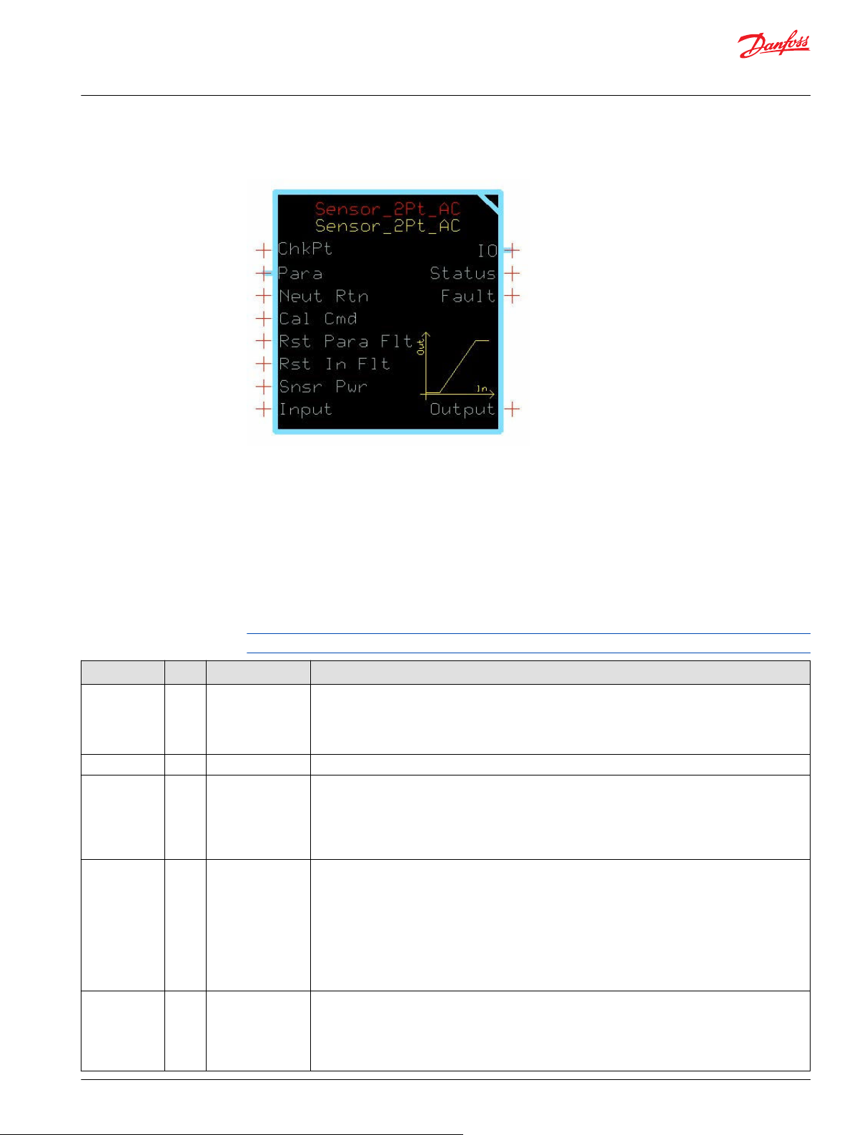
Sensor_2Pt_AC Function Block
The Sensor_2Pt_AC block converts a raw signal from a sensor into a percentage output.
This percentage output is based on the signal characteristics of the sensor. A built-in calibration routine
can capture the electrical signal at each end of the sensor’s range. This block scales its Output between
0% and +100%.
Reading analog sensors where piece-to-piece variation needs to be accounted for to ensure accuracy
•
of the signal.
Reading maximum speed potentiometers, trim steer potentiometers, and fuel-level sensors.
•
Inputs
The inputs to the Sensor_2Pt_AC function block are described.
Use only the data types specified in this table. Other data types cause compiler errors.
Item Type Range Description
ChkPt BOOL ——
Para Bus —— Brings external inputs (such as deadband parameters) into the function block.
Neut Rtn BOOL —— Neut Rtn (Neutral Return) sets when the function block enables its Output signals after a controller
Cal Cmd U8 0–3 Calibration command:
Rst Para Flt BOOL ——
True—include the function block’s built-in Advanced Checkpoint with Namespace in the compiled
•
LHX download file.
False—exclude the function block’s built-in Advanced Checkpoint with Namespace components
•
from the compiled LHX download file.
startup, calibration, or a fault or status condition.
True—Function block enables its Output signal after the Input returns to the neutral (zero percent)
•
position.
False—Function block immediately enables its Output signal.
•
•
0—Semi-automatic calibration disabled. If calibrated, the function block outputs the input
percentage the calibrated range. Cal_1 and Cal_2 can only change via the PLUS+1® Service Tool.
•
1—Semi-automatic calibration enabled. Capture values using autocalibration or directly download
values with the PLUS+1® Service Tool. In autocalibration, you manipulate the sensor to each
extremity and the function block captures values that fall within the defined windows.
•
2—Set Cal_1 and Cal_2 parameters to default values.
•
3—Clear calibration values. Set Cal_1 and Cal_2 to zero.
When the function block detects an invalid combination of parameters it sets a status condition and
disables the Output signal (Output = 0). The Rst Para Flt (Reset Parameter Fault) determines if the
function block enables the Output signal after the condition clears.
True—Function block immediately enables the Output signal.
•
False—Function block enables the Output signal after you repower the controller.
•
©
Danfoss | February 2019 11062082 | AQ00000274en-000102 | 35
Page 36
User Manual
PLUS+1® Compliant Function Block Library—Input Function Blocks
Sensor_2Pt_AC Function Block
Item Type Range Description
Rst In Flt BOOL ——
Snsr Pwr U16 0–65535 Snsr Pwr (Sensor Power) defines the reference for ratiometric calculations. If a sensor is ratiometric, the
Input U16 0–65535 Signal from the sensor. The units of this signal must be the same units for Snsr Pwr.
Outputs
The outputs of the Sensor_2Pt_AC function block are described.
Item Type Range Description
IO Bus —— Outputs a bus with all of the function block's input and output signals.
Status U16 —— Reports the status of the function block.
Fault U16 —— Reports the faults of the function block.
Output U16 0–10000 Percent of Input applied to the sensor’s calibrated range.
When the function block detects an Input failure it sets a fault condition and disables the Output signal
(Output = 0) The Rst In Flt (Reset Input Fault) determines if the block enables the Output signal after
the condition clears.
True—Function block immediately enables the Output signal.
•
False—Function block enables the Output signal after you repower the controller.
•
function block’s Output signal is continually compensated for variation in the supply. If the sensor is
not ratiometric, connect a constant value representing the full scale signal range.
This bus provides a convenient way to distribute this function block's signals to your application.
This output follows the standard bitwise scheme described in the Status Logic topic.
This output follows the standard bitwise scheme described in the Status Logic topic.
1000 = 10.00%
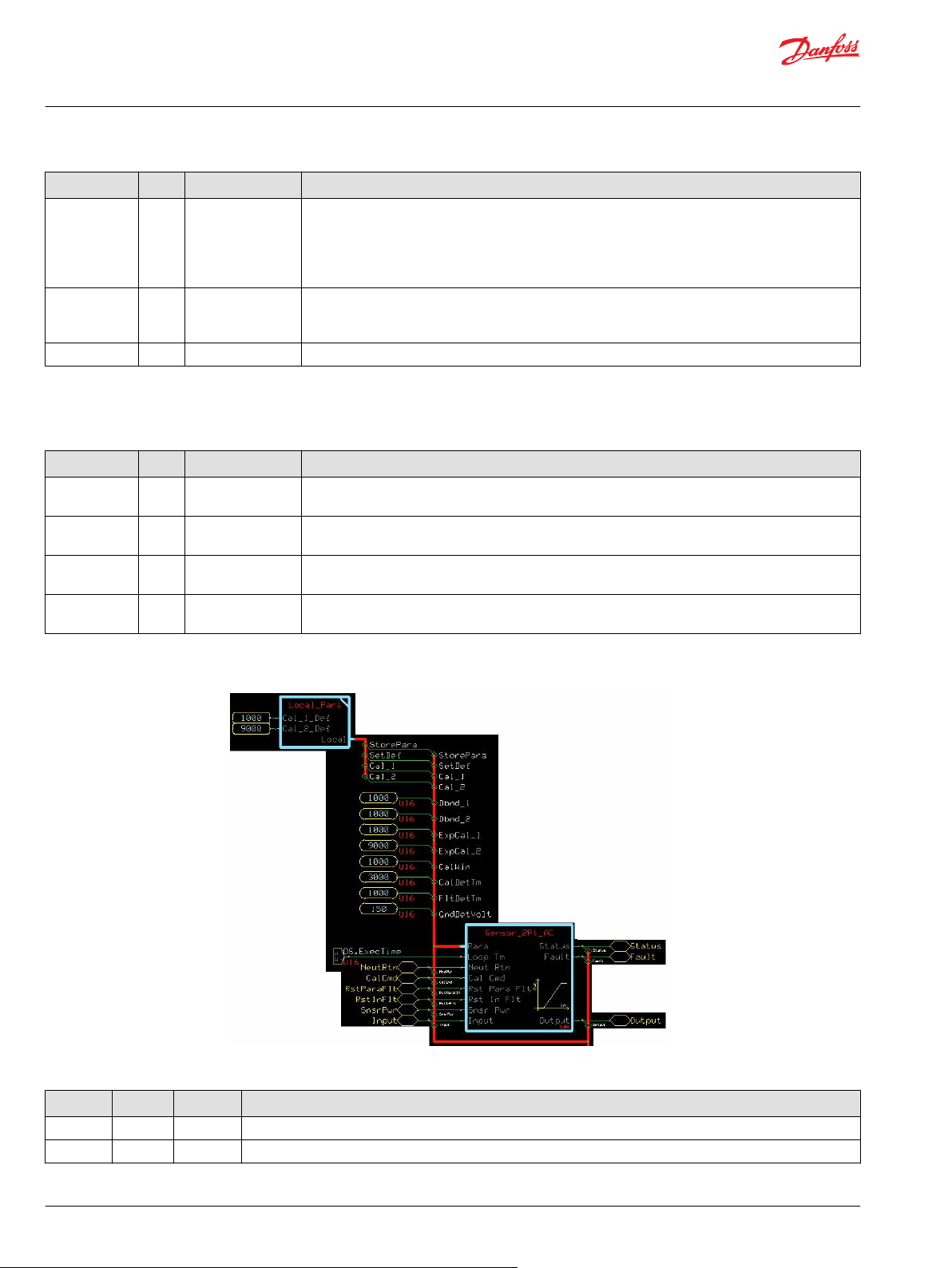
Configuration Settings
Function Block Configuration Settings
Input Type Range Description
StorePara BOOL —— StorePara (Store Parameter) is a signal from the block’s calibration function to store the current value in EEPROM.
Set Def BOOL —— Set Def (Set Defaults) is a signal from the block’s calibration function to reset the values stored in EEPROM.
36 | © Danfoss | February 2019 11062082 | AQ00000274en-000102
Page 37

User Manual
P
LUS+1® Compliant Function Block Library—Input Function Blocks
Sensor_2Pt_AC Function Block
Function Block Configuration Settings (continued)
Input Type Range Description
Cal_1 S16 0–10000 Cal_1 (Calibration Point 1) is the signal level associated with 0%
Cal_2 S16 0–10000 Cal_2 (Calibration Point 2) is the signal level associated with 100% Output. This is a percentage of Snsr Pwr.
Dbnd_1 U16 0–5000 Sets the width of the deadband at 0%.
Dbnd_2 U16 0–5000 Sets the width of the deadband at 100%.
ExpCal_1 U16 0–10000
ExpCal_2 U16 0–10000 ExpCal_2
CalWin U16 0–5000 Sets the width of the calibration window. The Input must fall within this window around the expected calibration
CalDetTm U16 0–65535 CalDetTm (Calibration Detection Time) sets the time after the Input enters a calibration window before the value
FltDetTm U16 0–65535 FltDetTm (Fault Detection Time) sets the time before an abnormal Input causes the function block to set a Fault
For the block to compile, this signal must be connected to a “Connect” type output that is bidirectional.
1000 = 10.00%
For the block to compile, this signal must be connected to a “Connect” type output that is bidirectional.
1000 = 10.00%
An Input within this deadband produces a 0% Output.
The function block sets the width of this deadband as a percentage of the difference between the Cal_1 and Cal_2
calibration values.
1000 = 10.00%
An Input within this deadband produces a 100% output.
The function block sets the width of this deadband as a percentage of the difference between the Cal_1 and Cal_2
calibration values.
1000 = 10.00%
ExpCal_1
Output. This is a percentage of Snsr Pwr.
1000 = 10.00%
100% Output. This is a percentage of Snsr Pwr.
1000 = 10.00%
point for the calibration detection time before the calibration point is saved.
is captured.
1000 = 1000 ms
condition.
1000 = 1000 ms
(Expected Calibration Point 1) sets the middle of the calibration window for semi-autocalibration for 0%
(Expected Calibration Point 2 sets the middle of the calibration window for semi-autocalibration for
Output. This is a percentage of Snsr Pwr.
©
Danfoss | February 2019
11062082 | AQ00000274en-000102 | 37
Page 38
User Manual
PLUS+1® Compliant Function Block Library—Input Function Blocks
Sensor_2Pt_AC Function Block
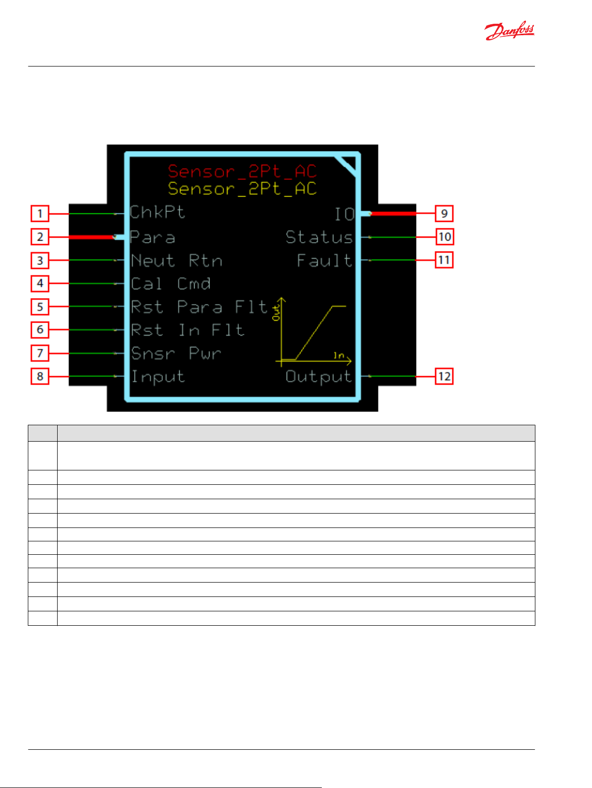
Function Block Connections
Connections you can make with the function block are described.
Description
Item
1
2 Bus interface for optional external inputs.
3 Force the input to return to the sensor’s zero position before allowing non-zero output after fault, status, or startup conditions.
4 Control and configuration of the built in calibration function.
5 Latch all detected parameter faults, forcing controller power cycle before clearing.
6 Latch all detected input faults, forcing controller power cycle before clearing.
7 Used to monitor the sensor’s power supply to make ratiometric adjustments within the function block.
8 Signal indicating the position of the sensor.
9 Outputs a bus with all of the function block's input and output signals.
10 Reports the status of the function block.
11 Reports the faults of the function block.
12 Position indicator of the sensor as a percent of its calibration range.
True—include the function block’s built-in Advanced Checkpoint with Namespace in the compiled LHX download file.
•
False—exclude the function block’s built-in Advanced Checkpoint with Namespace components from the compiled LHX download file.
•
38 | © Danfoss | February 2019 11062082 | AQ00000274en-000102
Page 39

User Manual
PLUS+1® Compliant Function Block Library—Input Function Blocks
Sensor_2Pt_AC Function Block
Status Logic
This topic describes how status logic is indicated for the function block.
Condition Hex
Block not calibrated. 0x8001 0001 Both Cal_1 and Cal_2 are zero.
Block partially
calibrated.
Invalid configuration. 0x8008 1000 One of the parameters and/or
*
Bit 16 set to 1 identifies a standard Danfoss status or fault code.
Fault Logic
Condition Hex
Input value is too low. 0x8001 0001 Input value is lower than halfway
Input value is too high. 0x8002 0010 Input value is higher than
Open circuit. 0x8004 0100 Input value is close to ground
Short circuit. 0x8008 1000 Input value is close to Snsr Pwr.
*
Bit 16 set to 1 identifies a standard Danfoss status or fault code.
*
Binary Cause Response Correction
0x8002 0010 Either Cal_1 or Cal_2 is zero. The
other is non-zero.
Snsr Pwr is outside its defined
range.
Output = 0
This topic describes how fault logic is indicated for the function block.
*
Binary Cause Response Correction
Output = 0 after a delay of
between the lowest calibration
point and Snsr Pwr.
halfway between the highest
calibration point and Snsr Pwr.
(0).
FltDetTm.
Output = 0 after a delay of
FltDetTm.
Output = 0 after a delay of
FltDetTm.
If Cal Cmd = 1, then Cal_1 and
Cal_2 are both set to zero.
Output = 0 after a delay of
FltDetTm.
Start calibration using Cal Cmd
and moving the sensor to each
extreme or set values through
the service tool.
Complete calibration using Cal
Cmd and moving the sensor to
each extreme or set values
through the service tool.
Review function parameters to
ensure they are within their valid
ranges.
Ensure the ExpCal and Cal
values are correct for the sensor.
Verify there is no wire or sensor
failure.
Calibration and Fault Values
This topic describes default calibration values are set, as well as how high and low fault values are
determined.
The following graph shows how the:
Default Cal_2_Def value defines the Input value (in mV) that produces an Output value of 10000.
•
Default Cal_1_Def value defines the Input value (in mV) that produces an Output value of 0.
•
Function block calculates the high and low fault values based on the high and low calibration points.
•
A CalCmd input of 2 applies default calibration values.
The function block has a Snsr Pwr input of 5000 mV.
©
Danfoss | February 2019 11062082 | AQ00000274en-000102 | 39
Page 40

User Manual
PLUS+1® Compliant Function Block Library—Input Function Blocks
Sensor_2Pt_AC Function Block
Deadband Values
Configuration settings you define produce high, medium, and low deadband ranges.
The following graph shows how the:
Dbnd_2, Cal_1_Def, and Cal_2_Def values define a deadband range in which Input values produce
•
a constant Output value of 10000.
Dbnd_1, Cal_1_Def, and Cal_2_Defvalues define a deadband range in which Input values produce
•
a constant Output value of 0.
(In an autocalibration procedure, captured calibration values define the upper and lower deadbands.)
A CalCmd input of 2 applies default calibration values.
The function block has a Snsr Pwr input of 5000 mV.
40 | © Danfoss | February 2019 11062082 | AQ00000274en-000102
Page 41

500
1000
0
1500 2000
2500
3000
Input (mV)
3500 4000
4500
5000
0
1000
2000
3000
4000
5000
6000
7000
8000
9000
10000
Output (10000 = 100.00%)
3000
Function Block Values
Cal_2_Def = 9000
Cal_1_Def = 1000
Dbnd_2 = 1000
Dbnd_1 = 1000
Cal Cmd = 2
Snsr Pwr = 5000 mV
Deadband Formulas
High deadband starts = (Snsr Pwr) x [Cal_2_Def* - (Dbnd_2) x (Cal2_Def – Cal1_Def)]
Low deadband starts = (Snsr Pwr) x [Cal_1_Def* + (Dbnd_1) x (Cal2_Def – Cal1_Def)]
*The auto-calibration procedure uses captured calibration values in these formulas.
Low deadband starts at 900 mV—the Output stays at 0 in this band
High deadband starts at 4100 mV—the Output stays at 10000 in this band
User Manual
PLUS+1® Compliant Function Block Library—Input Function Blocks
Sensor_2Pt_AC Function Block
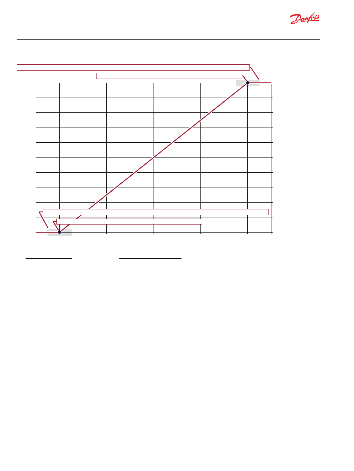
Calibration Windows
Configuration settings you define allow an auto-calibration procedure to capture high, medium, and low
calibration points.
The following graph shows how the:
ExpCal_2 and CalWin values define a window range in which an auto-calibration procedure can
•
capture a valid high calibration point.
ExpCal_1 and CalWin values define a window range in which an auto-calibration procedure can
•
capture a valid low calibration point.
A CalCmd input of 1 enables an auto-calibration procedure to capture calibration values.
The function block has a Snsr Pwr input of 5000 mV.
©
Danfoss | February 2019 11062082 | AQ00000274en-000102 | 41
Page 42
500
1000
0
1500 2000
2500
3000
Input (mV)
3500 4000
4500
5000
0
1000
2000
3000
4000
5000
6000
7000
8000
9000
10000
Output (10000 = 100.00%)
3000
Function Block Values
CalWin = 1000
ExpCal_2 = 9000
ExpCal_1 = 1000
Cal_2 = To be captured in autocalibration
Cal_1 = To be captured in autocalibration
Cal Cmd = 3
Snsr Pwr = 5000 mV
Calibration Window Formulas
Calibration window width (mV) = Snsr Pwr x CalWin
Center of upper calibration window = ExpCal_2 x Snsr Pwr
Upper calibration window range = ExpCal_2 ± (Calibration window width ÷ 2)
Center of lower calibration window = ExpCal_1 x Snsr Pwr
Lower calibration window range = ExpCal_1 ± (Calibration window width ÷ 2)
Upper calibration window—a valid Cal_2 value (high calibration point) can only be captured in this 4250–4750 mV range
ExpCal_2 x Snsr Pwr—the upper calibration window centers on this value
Lower calibration window—a valid Cal_1 value (low calibration point) can only be captured in this 250–750 mV range
ExpCal_1 x Snsr Pwr—the lower calibration window centers on this value
User Manual
PLUS+1® Compliant Function Block Library—Input Function Blocks
Sensor_2Pt_AC Function Block
Identical Function Blocks Need Different Namespace Values to Successfully Compile
If you use the same function block more than once in an application, you must change each function
block’s namespace value to avoid compiler errors.
All function blocks contain Advanced Checkpoint with Namespace components that enable the PLUS+1
Service Tool to read block input and output values.
Some function blocks contain non-volatile memory components that store function block operating
parameters.
Both these components use memory names (“aliases”) to allocate memory. Identical memory names
cause compiler errors.
The namespace value adds a unique prefix to each component name to avoid errors. Keep each
namespace value short to save controller memory.
®
42 | © Danfoss | February 2019 11062082 | AQ00000274en-000102
Page 43

User Manual
PLUS+1® Compliant Function Block Library—Input Function Blocks
Sensor_2Pt_AC Function Block
Change Namespace Value
To successfully compile your application, change the namespace value for function blocks that are used
more than once in an application.
1. In the PLUS+1® GUIDE menu bar, click the Query/Change button.
2. Click on the function block whose namespace you want to set to a unique value.
The Edit Page window opens.
3. In the Edit Page window, enter a meaningful Namespace value.
Namespace values are case-sensitive.
•
To save controller memory, use a short namespace value.
•
4. Press Enter.
5. Repeat these steps to enter unique namespace values for other identical function blocks.
©
Danfoss | February 2019 11062082 | AQ00000274en-000102 | 43
Page 44

User Manual
PLUS+1® Compliant Function Block Library—Input Function Blocks
Sensor_2Pt_AC Function Block
IEC 61508-3 Annex D Supplemental Information
The following table provides IEC 61508-3 Annex D supplemental information.
Item
Function block name Sensor_2Pt_AC
Function block version 4.0.
Function block development
environment
Compatible hardware
Function block developed in
compliance with
Competence required of
function block integrator
Contacting Danfoss
Description
PLUS+1® GUIDE version 8.1 and later.
Verified in the PLUS+1® GUIDE compile process.
When the PLUS+1® GUIDE compiler finds a function block that is incompatible with hardware, it aborts the compile
process and logs an error message. The error message gives the location of the function block and states “Error 80:
component not supported in hwd.”
Danfoss Software Product Development Process (PDP), which includes ISO 9001 and IEC 61508-3 standards.
The knowledge, competence, and training required to:
Understand this manual.
•
Use the PLUS+1® GUIDE program to develop a machine control application.
•
Follow quality software practices to develop a machine control application.
•
https://www.danfoss.com/en/products/software/dps/plus1-software-services-support-and-training/plus1-support-andservices
44 | © Danfoss | February 2019 11062082 | AQ00000274en-000102
Page 45
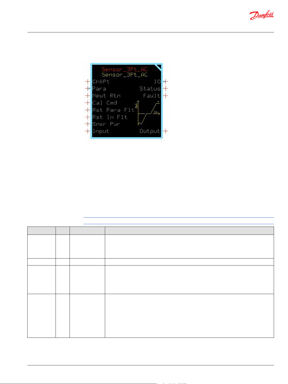
User Manual
PLUS+1® Compliant Function Block Library—Input Function Blocks
Sensor_3Pt_AC Function Block
The Sensor_3Pt_AC block converts a raw signal from a sensor into a percentage output.
This percentage output is based on signal characteristics of the sensor. A built-in calibration routine can
capture the electrical signal at each end of the sensor’s range. This block scales its Output between
-100% and 100%.
Typical uses for this function block include:
Reading analog sensors where piece-to-piece variation needs to be accounted for to ensure accuracy
•
of the signal.
Reading steering and angle sensors, bidirectional foot pedals and joysticks, and any other
•
potentiometric or hall sensors requiring 3 calibration points.
Inputs
The inputs to the Sensor_3Pt_AC function block are described.
Use only the data types specified in this table. Other data types cause compiler errors.
Item Type Range Description
ChkPt BOOL ——
Para Bus —— Brings external inputs (such as deadband parameters) into the function block.
Neut Rtn BOOL —— Neut Rtn (Neutral Return) sets when the function block enables its Output signals after a controller
Cal Cmd U8 0–3 Calibration command:
True—include the function block’s built-in Advanced Checkpoint with Namespace in the compiled
•
LHX download file.
False—exclude the function block’s built-in Advanced Checkpoint with Namespace components
•
from the compiled LHX download file.
startup, calibration, or a fault or status condition.
True—Function block enables its Output signal after the Input returns to the neutral (zero percent)
•
position.
False—Function block immediately enables its Output signal.
•
0—semi-automatic calibration disabled. If calibrated, the block outputs the input percentage the
calibrated range. Cal_1, Cal_2, and Cal_3 can only change via the PLUS+1® Service Tool.
•
1—Semi-automatic calibration enabled. Capture values using autocalibration or directly download
values with the PLUS+1® Service Tool. In autocalibration, you manipulate the sensor to each
extremity and the function block captures values that fall within the defined windows.
•
2—Set Cal_1, Cal_2, and Cal_3 parameters to default values.
•
3—Clear calibration values. Set Cal_1, Cal_2, and Cal_3 to zero.
©
Danfoss | February 2019 11062082 | AQ00000274en-000102 | 45
Page 46
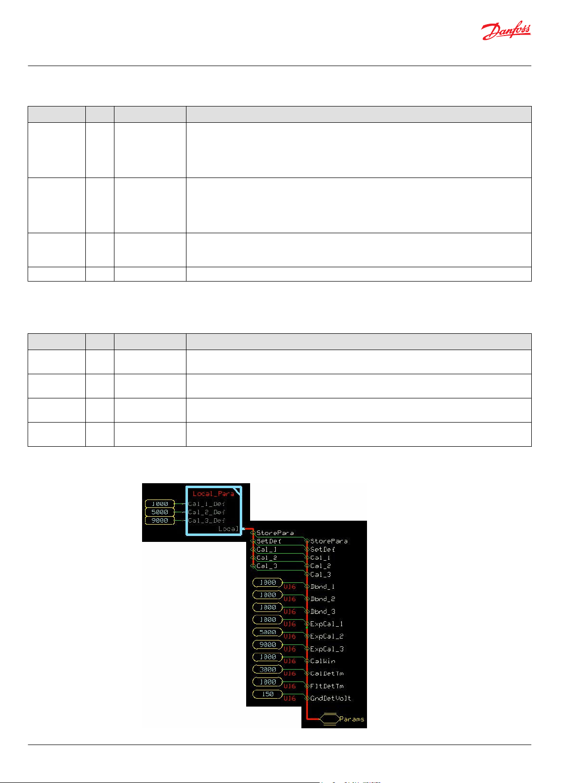
User Manual
PLUS+1® Compliant Function Block Library—Input Function Blocks
Sensor_3Pt_AC Function Block
Item Type Range Description
Rst Para Flt BOOL ——
Rst In Flt BOOL ——
Snsr Pwr U16 0–65535 Snsr Pwr (Sensor Power) defines the reference for ratiometric calculations. If a sensor is ratiometric, the
Input U16 0–65535 Signal from the sensor. The units of this signal must be the same units for Snsr Pwr.
Outputs
The outputs of the Sensor_3Pt_AC function block are described.
When the function block detects an invalid combination of parameters it sets a status condition and
disables the Output signal (Output = 0). The Rst Para Flt (Reset Parameter Fault) determines if the
function block enables the Output signal after the condition clears.
True—Function block immediately enables the Output signal.
•
False—Function block enables the Output signal after you repower the controller.
•
When the function block detects an Input failure it sets a fault condition and disables the Output signal
(Output = 0) The Rst In Flt (Reset Input Fault) determines if the block enables the Output signal after
the condition clears.
True—Function block immediately enables the Output signal.
•
False—Function block enables the Output signal after you repower the controller.
•
function block’s Output signal is continually compensated for variation in the supply. If the sensor is
not ratiometric, connect a constant value representing the full scale signal range.
Item Type Range Description
IO Bus —— Outputs a bus with all of the function block's input and output signals.
This bus provides a convenient way to distribute this function block's signals to your application.
Status U16 —— Reports the status of the function block.
This output follows the standard bitwise scheme described in the Status Logic topic.
Fault U16 —— Reports the faults of the function block.
This output follows the standard bitwise scheme described in the Status Logic topic.
Output S16 -10000–10000 Percent of Input applied to the sensor’s calibrated range.
1000 = 10.00%
Configuration Settings
46 | © Danfoss | February 2019 11062082 | AQ00000274en-000102
Page 47

User Manual
PLUS+1® Compliant Function Block Library—Input Function Blocks
Sensor_3Pt_AC Function Block
Function Block Configuration Settings
Input Type Range Description
StorePara BOOL —— StorePara (Store Parameter) is a signal from the block’s calibration function to store the current value in EEPROM.
Set Def BOOL —— Set Def (Set Defaults) is a signal from the block’s calibration function to reset the values stored in EEPROM.
Cal_1 S16 0–10000 Cal_1 (Calibration Point 1) is the signal level associated with -100% Output. This is a percentage of Snsr Pwr.
For the block to compile, this signal must be connected to a “Connect” type output that is bidirectional.
1000 = 10.00%
Cal_2 S16 0–10000 Cal_2 (Calibration Point 2) is the signal level associated with 0% Output. This is a percentage of Snsr Pwr.
For the block to compile, this signal must be connected to a “Connect” type output that is bidirectional.
1000 = 10.00%
Cal_3 S16 0–10000 Cal_3 (Calibration Point 3) is the signal level associated with 100% Output. This is a percentage of Snsr Pwr.
For the block to compile, this signal must be connected to a “Connect” type output that is bidirectional.
1000 = 10.00%
Dbnd_1 U16 0–5000 Sets the width of the deadband at 0%.
An input within this deadband produces a -100% Output.
The function block sets the width of this deadband as a percentage of the difference between the Cal_1 and Cal_2
calibration values.
1000 = 10.00%
Dbnd_2 U16 0–5000 Sets the width of the deadband at 100%.
An input within this deadband produces a 0% Output.
The function block sets the width of this deadband as a percentage of the difference between the Cal_1 and Cal_2
calibration values for Input below Cal_2 and as a percentage of the difference between the Cal_2 and Cal_3
calibration values for Input above Cal_2.
1000 = 10.00%
Dbnd_3 U16 0–5000 Sets the width of the deadband at 100%.
An input within this deadband produces a 100% output.
The function block sets the width of this deadband as a percentage of the difference between the Cal_2 and Cal_3
calibration values.
1000 = 10.00%
ExpCal_1 U16 0–10000 ExpCal_1 (Expected Calibration Point 1) sets the middle of the calibration window for semi-autocalibration for
-100% Output. This is a percentage of Snsr Pwr.
1000 = 10.00%
ExpCal_2 U16 0–10000 ExpCal_2 (Expected Calibration Point 2) sets the middle of the calibration window for semi-autocalibration for 0%
Output. This is a percentage of Snsr Pwr.
1000 = 10.00%
ExpCal_3 U16 0–10000 ExpCal_3 (Expected Calibration Point 3) sets the middle of the calibration window for semi-autocalibration for
100% Output. This is a percentage of Snsr Pwr.
1000 = 10.00%
CalWin U16 0–5000 Sets the width of the calibration window. The input must fall within this window around the expected calibration
point for the calibration detection time before the calibration point is saved.
CalDetTm U16 0–65535 CalDetTm (Calibration Detection Time) sets the time after the input enters a calibration window before the value is
captured.
1000 = 1000 ms
FltDetTm U16 0–65535 FltDetTm (Fault Detection Time) sets the time before an abnormal input causes the function block to set a Fault
condition.
1000 = 1000 ms
©
Danfoss | February 2019 11062082 | AQ00000274en-000102 | 47
Page 48

User Manual
PLUS+1® Compliant Function Block Library—Input Function Blocks
Sensor_3Pt_AC Function Block
Function Block Connections
Connections you can make with the function block are described.
Description
Item
1
2 Bus interface for optional external inputs.
3 Force the input to return to the sensor’s zero position before allowing non-zero output after fault, status, or startup conditions.
4 Control and configuration of the built in calibration function.
5 Latch all detected parameter faults, forcing controller power cycle before clearing.
6 Latch all detected input faults, forcing controller power cycle before clearing.
7 Used to monitor the sensor’s power supply to make ratiometric adjustments within the function block.
8 Signal indicating the position of the sensor.
9 Outputs a bus with all of the function block's input and output signals.
10 Reports the status of the function block.
11 Reports the faults of the function block.
12 Position indicator of the sensor as a percent of its calibration range.
True—include the function block’s built-in Advanced Checkpoint with Namespace in the compiled LHX download file.
•
False—exclude the function block’s built-in Advanced Checkpoint with Namespace components from the compiled LHX download file.
•
48 | © Danfoss | February 2019 11062082 | AQ00000274en-000102
Page 49
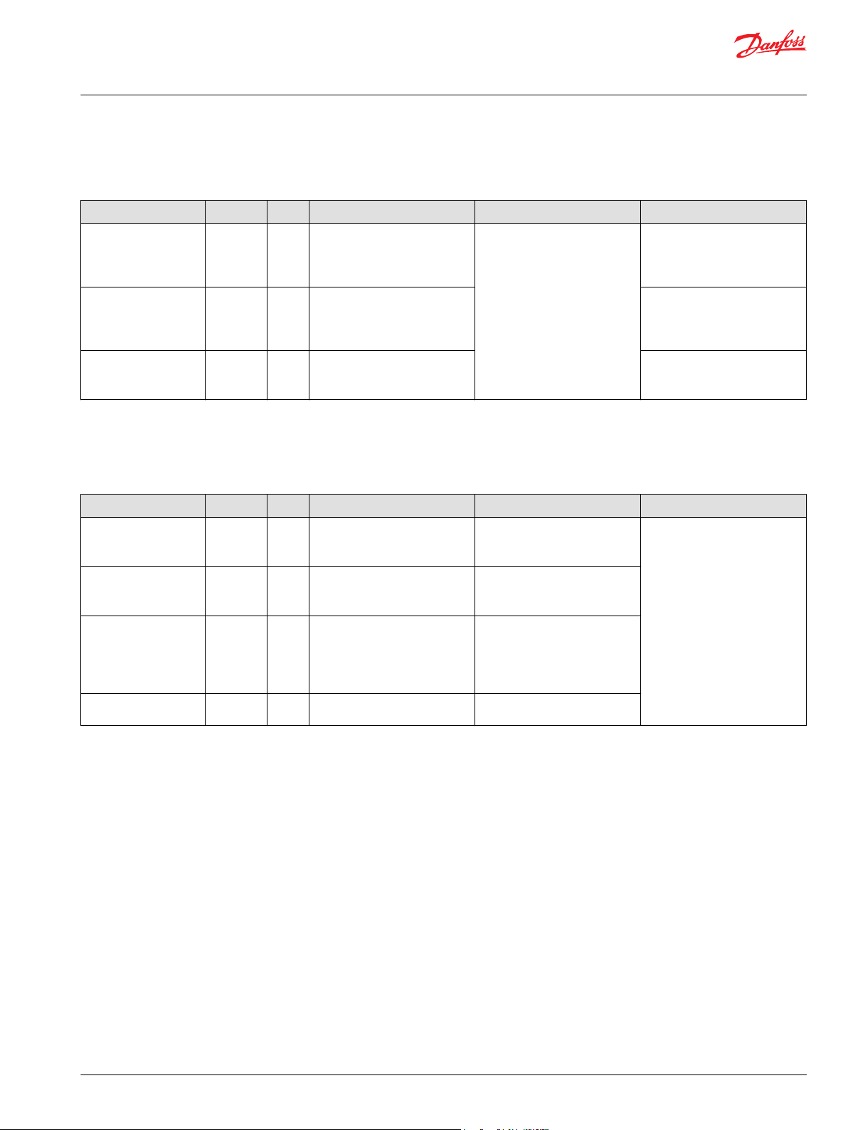
User Manual
PLUS+1® Compliant Function Block Library—Input Function Blocks
Sensor_3Pt_AC Function Block
Status Logic
This topic describes how status logic is indicated for the function block.
Condition Hex
Block not calibrated. 0x8001 0001 Both Cal_1, Cal_2, and Cal_3 are
Block partially
calibrated.
Invalid configuration. 0x8008 1000 One of the parameters and/or
*
Bit 16 set to 1 identifies a standard Danfoss status or fault code.
Fault Logic
Condition Hex
Input value is too low. 0x8001 0001 Input value is lower than halfway
Input value is too high. 0x8002 0010 Input value is higher than
Open circuit. 0x8004 0100 Input value is close to ground
Short circuit. 0x8008 1000 Input value is close to Snsr Pwr.
*
Bit 16 set to 1 identifies a standard Danfoss status or fault code.
*
Binary Cause Response Correction
zero.
0x8002 0010 One or two of the following are
zero: Cal_1, Cal_2, Cal_3. The
other(s) are non-zero.
Snsr Pwr is outside its defined
range.
Output = 0
This topic describes how fault logic is indicated for the function block.
*
Binary Cause Response Correction
Output = 0 after a delay of
between the lowest calibration
point and Snsr Pwr.
halfway between the highest
calibration point and Snsr Pwr.
(0).
FltDetTm.
Output = 0 after a delay of
FltDetTm.
Output = 0 after a delay of
FltDetTm.
If Cal Cmd = 1, then Cal_1,
Cal_2, and Cal_3 are both set to
zero.
Output = 0 after a delay of
FltDetTm.
Start calibration using Cal Cmd
and moving the sensor to each
extreme or set values through
the service tool.
Complete calibration using Cal
Cmd and moving the sensor to
each extreme or set values
through the service tool.
Review function parameters to
ensure they are within their valid
ranges.
Ensure the ExpCal and Cal
values are correct for the sensor.
Verify there is no wire or sensor
failure.
Calibration and Fault Values
The graph shows how the function block sets high and low calibration points, as well as how s the high
and low fault values are determined based on the high and low calibration points.
The following graph shows how the:
Default Cal_3_Def value defines the Input value (in mV) that produces an Output value of 10000.
•
Default Cal_2_Def value defines the Input value (in mV) that produces an Output value of 0.
•
Default Cal_1_Def value defines the Input value (in mV) that produces an Output value of -10000.
•
Function block calculates the high and low fault values based on the high and low calibration points.
•
A CalCmd input of 2 applies default calibration values.
The function block has a Snsr Pwr input of 5000 mV.
©
Danfoss | February 2019 11062082 | AQ00000274en-000102 | 49
Page 50

User Manual
PLUS+1® Compliant Function Block Library—Input Function Blocks
Sensor_3Pt_AC Function Block
Deadband Values
Configuration settings you define produce high, medium, and low deadband ranges.
The following graph shows how the:
Dbnd_3, Cal_2_Def, and Cal_3_Def values define a high deadband range in which Input values
•
produce a constant Output value of 10000.
Dbnd_2, Cal_1_Def, Cal_2_Defand Cal_3_Def values define a middle deadband range in which
•
Input values produce a constant Outputvalue of 0.
Dbnd_1, Cal_1_Def, and Cal_2_Def values define a low deadband range in which Input values
•
produce a constant Output value of -10000.
(In an auto-calibration procedure, captured calibration values define the deadbands.)
A CalCmd input of 2 applies default calibration values.
The function block has a Snsr Pwr input of 5000 mV.
50 | © Danfoss | February 2019 11062082 | AQ00000274en-000102
Page 51
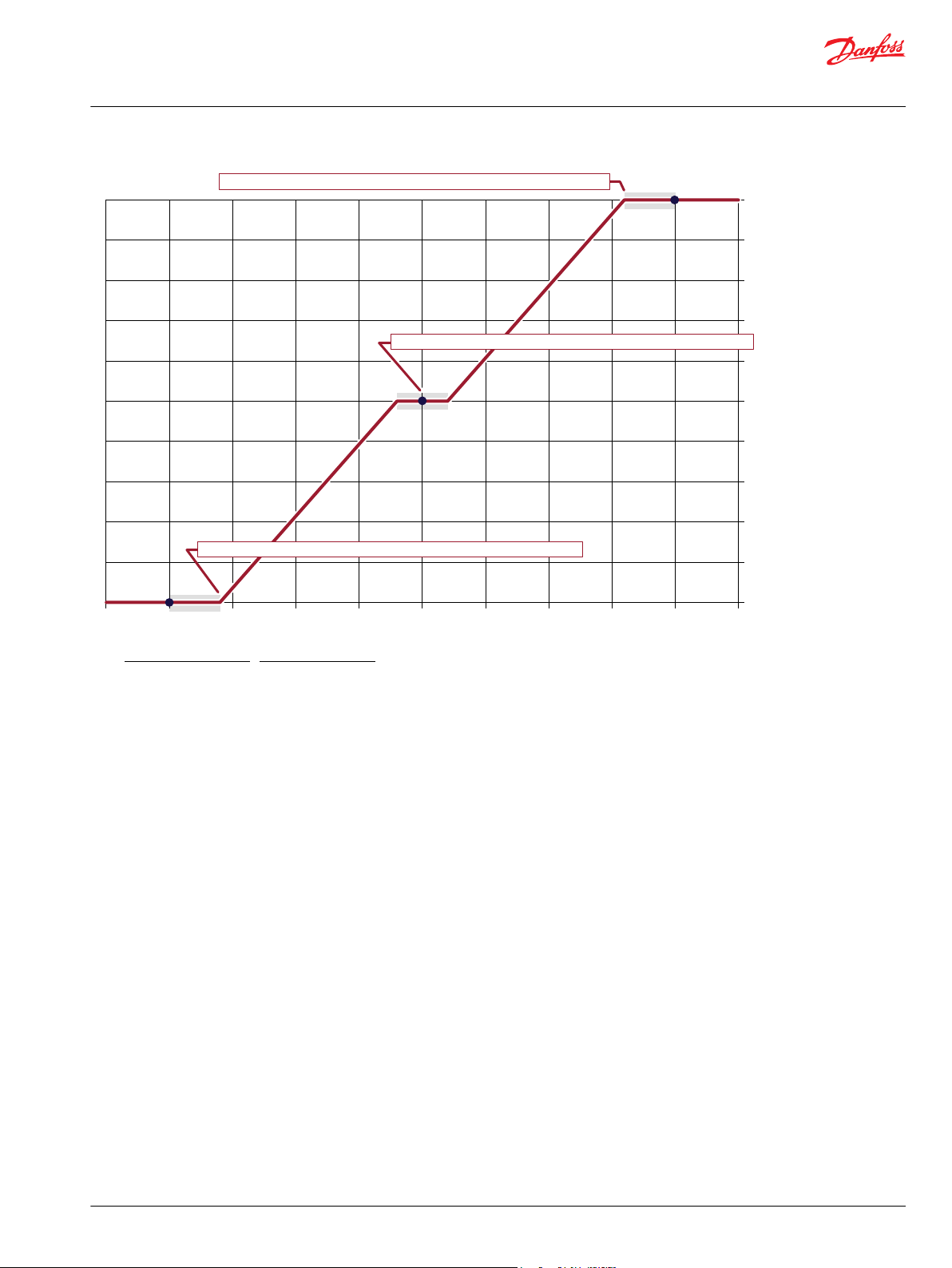
500
1000
0
1500 2000
2500
3000
Input (mV)
3500 4000
4500
5000
-10000
-8000
-6000
-4000
-2000
0
2000
4000
6000
8000
10000
Output (10000 = 100.00%)
3000
Function Block Values
Cal_3_Def = 9000
Cal_2_Def = 5000
Cal_1_Def = 1000
Dbnd_3 = 1000
Dbnd_2 = 1000
Dbnd_1 = 1000
Cal Cmd = 2
Snsr Pwr = 5000 mV
Deadband Formulas
High deadband starts = (Snsr Pwr) x [Cal_3_Def* - (Dbnd_3) x (Cal3_Def – Cal2_Def)]
Middle deadband starts = (Snsr Pwr) x [Cal_2_Def* - (Dbnd_2) x (Cal_2_Def - Cal_1_Def)]
Middle deadband ends = (Snsr Pwr) x [Cal_2_Def* + (Dbnd_2) x (Cal_3_Def - Cal_2_Def)]
Low deadband starts = (Snsr Pwr) x [Cal_1_Def* + (Dbnd_1) x (Cal2_Def – Cal1_Def)]
*The auto-calibration procedure uses captured calibration values in these formulas.
Low deadband starts at 900 mV—the Output stays at -10000 in this band
High deadband starts at 4100 mV—the Output stays at 10000 in this band
Middle deadband 2300–2700 mV—the Output stays at 0 in this band
User Manual
PLUS+1® Compliant Function Block Library—Input Function Blocks
Sensor_3Pt_AC Function Block
Calibration Windows
©
Danfoss | February 2019 11062082 | AQ00000274en-000102 | 51
Configuration settings you define allow an auto-calibration procedure to capture high, medium, and low
calibration points.
The following graph shows how the:
ExpCal_3 and CalWin values define a window range in which an auto-calibration procedure can
•
capture a valid high calibration point.
ExpCal_2 and CalWin values define a window range in which an auto-calibration procedure can
•
capture a valid middle calibration point.
ExpCal_1 and CalWin values define a window range in which an auto-calibration procedure can
•
capture a valid low calibration point.
A CalCmd input of 1 enables an auto-calibration procedure to capture calibration values.
The function block has a Snsr Pwr input of 5000 mV.
Page 52

500
1000
0
1500 2000
2500
3000
Input (mV)
3500 4000
4500
5000
-10000
-8000
-6000
-4000
-2000
0
2000
4000
6000
8000
10000
Output (10000 = 100.00%)
3000
Upper calibration window—a valid Cal_3 value (high calibration point) can only be captured in this 4250–4750 mV range
ExpCal_3 x Snsr Pwr—the upper calibration window centers on this value
Lower calibration window—a valid Cal_1 value (low calibration point) can only be captured in this 250–750 mV range
ExpCal_1 x Snsr Pwr—the lower calibration window centers on this value
ExpCal_2 x Snsr Pwr—the middle calibration window centers on this value
Middle calibration window—a valid Cal_2 value (middle calibration point)
can only be captured in this 2250–2750 mV range
Function Block Values
CalWin = 1000
ExpCal_3 = 9000
ExpCal_2 = 5000
ExpCal_1 = 1000
Cal_3 = To be captured in auto-calibration
Cal_2 = To be captured in auto-calibration
Cal_1 = To be captured in auto-calibration
Cal Cmd = 3
Snsr Pwr = 5000 mV
Calibration Window Formulas
Calibration window width (mV) = Snsr Pwr x CalWin
Center of upper calibration window = ExpCal_3 x Snsr Pwr
Upper calibration window range = ExpCal_3 ± (Calibration window width ÷ 2)
Center of middle calibration window = ExpCal_2 x Snsr Pwr
Middle calibration window range = ExpCal_2 ± (Calibration window width ÷ 2)
Center of lower calibration window = ExpCal_2 x Snsr Pwr
Lower calibration window range = ExpCal_1 ± (Calibration window width ÷ 2)
User Manual
PLUS+1® Compliant Function Block Library—Input Function Blocks
Sensor_3Pt_AC Function Block
Identical Function Blocks Need Different Namespace Values to Successfully Compile
If you use the same function block more than once in an application, you must change each function
block’s namespace value to avoid compiler errors.
All function blocks contain Advanced Checkpoint with Namespace components that enable the PLUS+1
Service Tool to read block input and output values.
Some function blocks contain non-volatile memory components that store function block operating
52 | © Danfoss | February 2019 11062082 | AQ00000274en-000102
parameters.
Both these components use memory names (“aliases”) to allocate memory. Identical memory names
cause compiler errors.
The namespace value adds a unique prefix to each component name to avoid errors. Keep each
namespace value short to save controller memory.
®
Page 53

User Manual
PLUS+1® Compliant Function Block Library—Input Function Blocks
Sensor_3Pt_AC Function Block
Change Namespace Value
To successfully compile your application, change the namespace value for function blocks that are used
more than once in an application.
1. In the PLUS+1® GUIDE menu bar, click the Query/Change button.
2. Click on the function block whose namespace you want to set to a unique value.
The Edit Page window opens.
3. In the Edit Page window, enter a meaningful Namespace value.
Namespace values are case-sensitive.
•
To save controller memory, use a short namespace value.
•
4. Press Enter.
5. Repeat these steps to enter unique namespace values for other identical function blocks.
©
Danfoss | February 2019 11062082 | AQ00000274en-000102 | 53
Page 54

User Manual
PLUS+1® Compliant Function Block Library—Input Function Blocks
Sensor_3Pt_AC Function Block
IEC 61508-3 Annex D Supplemental Information
The following table provides IEC 61508-3 Annex D supplemental information.
Item
Function block name Sensor_3Pt_AC
Function block version 4.0.
Function block development
environment
Compatible hardware
Function block developed in
compliance with
Competence required of
function block integrator
Contacting Danfoss
Description
PLUS+1® GUIDE version 8.1 and later.
Verified in the PLUS+1® GUIDE compile process.
When the PLUS+1® GUIDE compiler finds a function block that is incompatible with hardware, it aborts the compile
process and logs an error message. The error message gives the location of the function block and states “Error 80:
component not supported in hwd.”
Danfoss Software Product Development Process (PDP), which includes ISO 9001 and IEC 61508-3 standards.
The knowledge, competence, and training required to:
Understand this manual.
•
Use the PLUS+1® GUIDE program to develop a machine control application.
•
Follow quality software practices to develop a machine control application.
•
https://www.danfoss.com/en/products/software/dps/plus1-software-services-support-and-training/plus1-support-andservices
54 | © Danfoss | February 2019 11062082 | AQ00000274en-000102
Page 55

User Manual
PLUS+1® Compliant Function Block Library—Input Function Blocks
Freq_to_RPM Function Block
The Freq_to_RPM block calculates a rotational speed using a frequency signal.
Typical uses for this function block include:
Showing engine, pump or motor speed on a vehicle dashboard display.
•
Closed-loop speed control.
•
Straight-tracking propel control.
•
Determining engine, pump, motor, wheel, and other work function speeds through a Pulse Pick Up
•
(PPU) sensor.
There is no built-in detection for hardware wire faults within this function block. If fault detection is
required, it must be added outside this function block.
Inputs
The inputs to the Freq_to_RPM function block are described.
Use only the data types specified in this table. Other data types cause compiler errors.
Item Type Range Description
ChkPt BOOL ——
Freq U16 0–50000 Frequency (Hz)—Signal from PPU or other similar device.
Puls/Rev U16 0–50000 Pulses Per Revolution—Number of pulses in one revolution.
True—include the function block’s built-in Advanced Checkpoint with Namespace in the compiled
•
LHX download file.
False—exclude the function block’s built-in Advanced Checkpoint with Namespace components
•
from the compiled LHX download file.
10 = 10 mm
10 = 10 pulse/revolution.
Outputs
The outputs of the Freq_to_RPM function block are described.
Item Type Range Description
IO Bus —— Outputs a bus with all of the function block's input and output signals.
This bus provides a convenient way to distribute this function block's signals to your application.
Status U16 —— Reports the status of the function block.
This output follows the standard bitwise scheme described in the Status Logic topic.
Fault U16 —— Reports the faults of the function block.
Output U32 0–3000000 Rotational speed based on the Freq and Puls/Rev inputs.
This output follows the standard bitwise scheme described in the Status Logic topic.
1000 = 1000 RPM
©
Danfoss | February 2019 11062082 | AQ00000274en-000102 | 55
Page 56

User Manual
PLUS+1® Compliant Function Block Library—Input Function Blocks
Freq_to_RPM Function Block
Function Block Connections
Connections you can make with the function block are described.
Description
Item
1
2 Used to monitor frequency of the sensor pulses.
3 Configuration for setting the number of pulses per revolution.
4 Outputs a bus with all of the function block's input and output signals.
5 Reports the status of the function block.
6 Reports the faults of the function block.
7 Calculated RPM from the input signals.
True—include the function block’s built-in Advanced Checkpoint with Namespace in the compiled LHX download file.
•
False—exclude the function block’s built-in Advanced Checkpoint with Namespace components from the compiled LHX download file.
•
Status Logic
This topic describes how status logic is indicated for the function block.
Condition Hex
Invalid configuration. 0x8008 1000 Puls/Rev parameter is outside its
*
Bit 16 set to 1 identifies a standard Danfoss status or fault code.
*
Binary Cause Response Correction
Output signal is calculated using
defined range.
the parameters clamped to their
respective ranges.
Review function parameters to
ensure they are within their valid
ranges.
Fault Logic
This topic describes how fault logic is indicated for the function block.
Condition Hex
Input value is too low. 0x8001 0001 Freq < 0. Output = 0 Verify the input signal is correct.
Input value is too high. 0x8002 0010 Freq > 50000. Output signal is calculated using
*
Bit 16 set to 1 identifies a standard Danfoss status or fault code.
*
Binary Cause Response Correction
Freq = 50000.
If a signed signal is received from
the sensor to indicated direction,
then use the absolute value.
Verify there is no noise
introduced to the input signal
and that the sensor’s output
range is within the Freq limit.
56 | © Danfoss | February 2019 11062082 | AQ00000274en-000102
Page 57
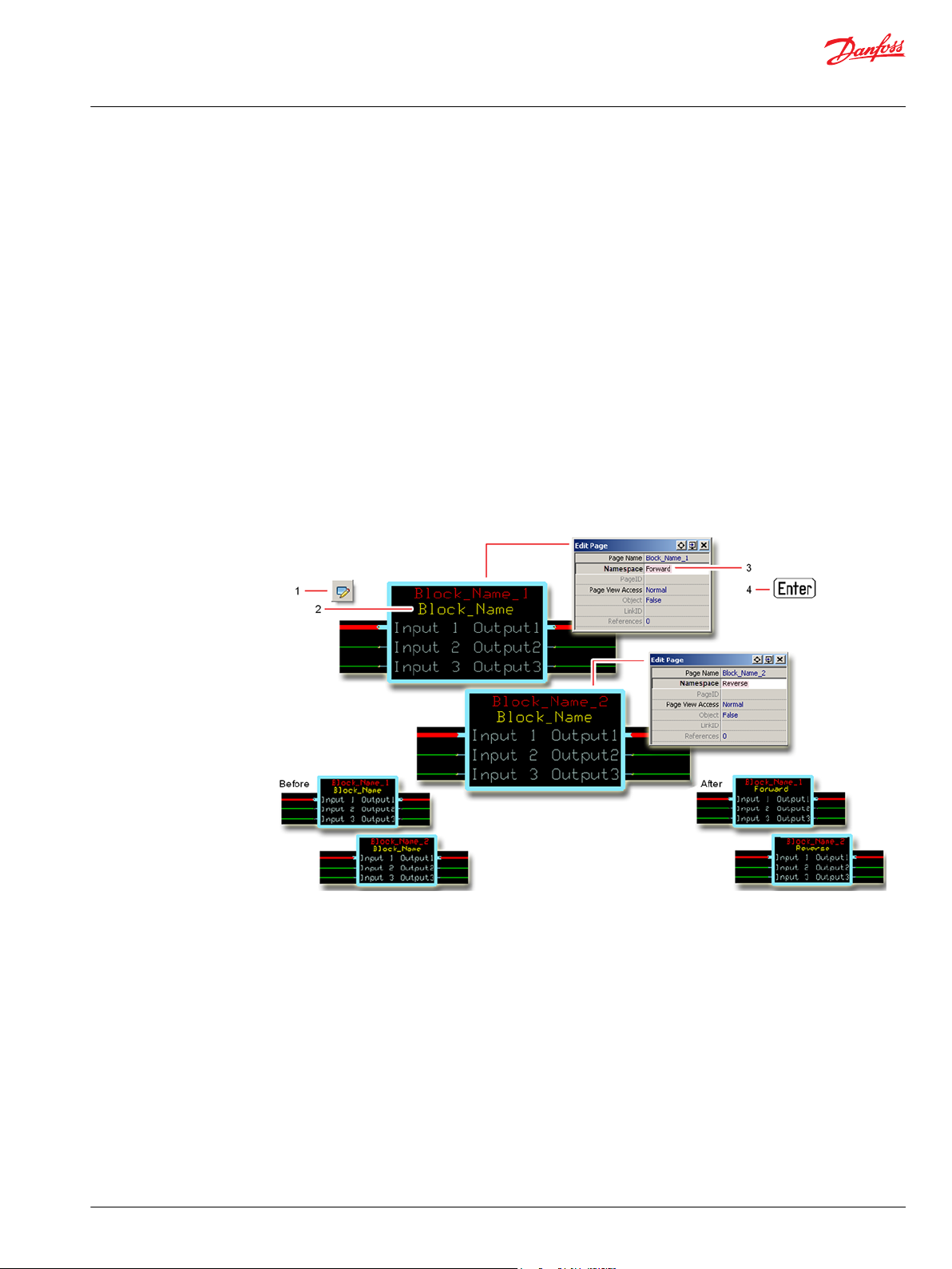
User Manual
PLUS+1® Compliant Function Block Library—Input Function Blocks
Freq_to_RPM Function Block
Identical Function Blocks Need Different Namespace Values to Successfully Compile
If you use the same function block more than once in an application, you must change each function
block’s namespace value to avoid compiler errors.
All function blocks contain Advanced Checkpoint with Namespace components that enable the PLUS+1
Service Tool to read block input and output values.
Some function blocks contain non-volatile memory components that store function block operating
parameters.
Both these components use memory names (“aliases”) to allocate memory. Identical memory names
cause compiler errors.
The namespace value adds a unique prefix to each component name to avoid errors. Keep each
namespace value short to save controller memory.
Change Namespace Value
To successfully compile your application, change the namespace value for function blocks that are used
more than once in an application.
®
1. In the PLUS+1® GUIDE menu bar, click the Query/Change button.
2. Click on the function block whose namespace you want to set to a unique value.
The Edit Page window opens.
3. In the Edit Page window, enter a meaningful Namespace value.
Namespace values are case-sensitive.
•
To save controller memory, use a short namespace value.
•
4. Press Enter.
5. Repeat these steps to enter unique namespace values for other identical function blocks.
©
Danfoss | February 2019 11062082 | AQ00000274en-000102 | 57
Page 58

User Manual
PLUS+1® Compliant Function Block Library—Input Function Blocks
Freq_to_RPM Function Block
IEC 61508-3 Annex D Supplemental Information
The following table provides IEC 61508-3 Annex D supplemental information.
Item
Function block name Freq_to_RPM
Function block version 4.0.
Function block development
environment
Compatible hardware
Function block developed in
compliance with
Competence required of
function block integrator
Contacting Danfoss
Description
PLUS+1® GUIDE version 8.1 and later.
Verified in the PLUS+1® GUIDE compile process.
When the PLUS+1® GUIDE compiler finds a function block that is incompatible with hardware, it aborts the compile
process and logs an error message. The error message gives the location of the function block and states “Error 80:
component not supported in hwd.”
Danfoss Software Product Development Process (PDP), which includes ISO 9001 and IEC 61508-3 standards.
The knowledge, competence, and training required to:
Understand this manual.
•
Use the PLUS+1® GUIDE program to develop a machine control application.
•
Follow quality software practices to develop a machine control application.
•
https://www.danfoss.com/en/products/software/dps/plus1-software-services-support-and-training/plus1-support-andservices
58 | © Danfoss | February 2019 11062082 | AQ00000274en-000102
Page 59

User Manual
PLUS+1® Compliant Function Block Library—Input Function Blocks
Freq_to_Speed Function Block
The Freq_to_Speed block calculates a linear speed using a frequency signal.
Typical uses for this function block include:
Cruise control.
•
Closed-loop speed control.
•
Straight-tracking propel control.
•
Determining vehicle ground speed through a Pulse Pick Up (PPU) sensor on a motor.
•
There is no built-in detection for hardware wire faults within this function block. If fault detection is
required, it must be added outside this function block.
Inputs
The inputs to the Freq_to_Speed function block are described.
Use only the data types specified in this table. Other data types cause compiler errors.
Item Type Range Description
ChkPt BOOL ——
Freq U16 0–50000 Frequency (Hz)—Signal from PPU or other similar device.
Whl Dia U16 0–10000 Effective diameter of the wheel.
Puls/Rev U16 0–50000 Pulses Per Revolution—Number of pulses in one revolution.
True—include the function block’s built-in Advanced Checkpoint with Namespace in the compiled
•
LHX download file.
False—exclude the function block’s built-in Advanced Checkpoint with Namespace components
•
from the compiled LHX download file.
10 = 10 mm
10 = 10 Hz
10 = 10 pulse/revolution.
Outputs
The outputs of the Freq_to_Speed function block are described.
Item Type Range Description
IO Bus —— Outputs a bus with all of the function block's input and output signals.
This bus provides a convenient way to distribute this function block's signals to your application.
Status U16 —— Reports the status of the function block.
This output follows the standard bitwise scheme described in the Status Logic topic.
©
Danfoss | February 2019 11062082 | AQ00000274en-000102 | 59
Page 60

User Manual
PLUS+1® Compliant Function Block Library—Input Function Blocks
Freq_to_Speed Function Block
Item Type Range Description
Fault U16 —— Reports the faults of the function block.
This output follows the standard bitwise scheme described in the Status Logic topic.
Speed U32
0 to 565486200
Linear speed based on the Freq, Whl Dia, and Puls/Rev inputs.
1000 = 10.00 km/h
60 | © Danfoss | February 2019 11062082 | AQ00000274en-000102
Page 61
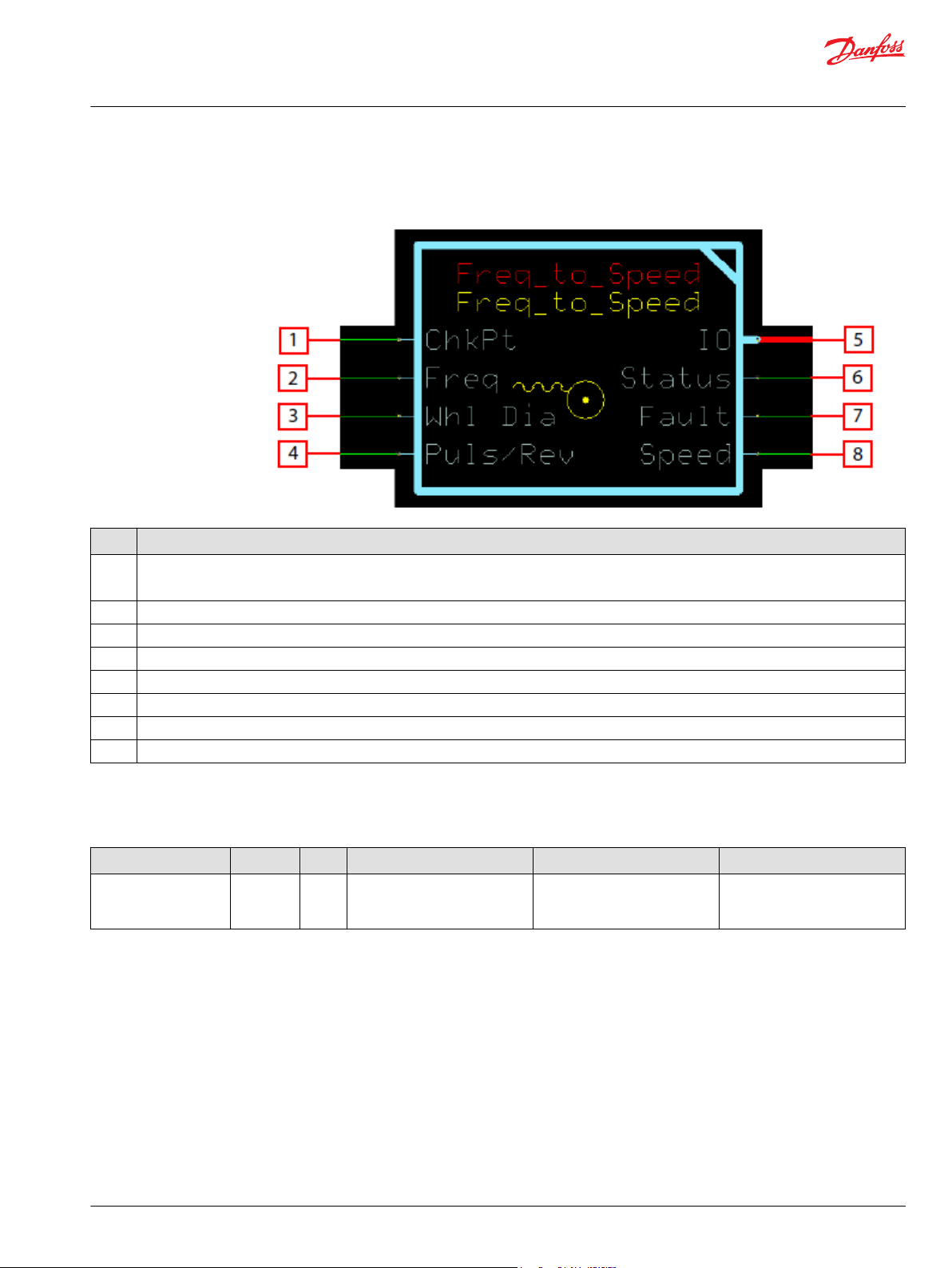
User Manual
PLUS+1® Compliant Function Block Library—Input Function Blocks
Freq_to_Speed Function Block
Function Block Connections
Connections you can make with the function block are described.
Description
Item
1
2 Used to monitor frequency of the sensor pulses.
3
4 Configuration for setting the number of pulses per revolution.
5 Outputs a bus with all of the function block's input and output signals.
6 Reports the status of the function block.
7 Reports the faults of the function block.
8 Speed output calculated from Freq, Whl Dia, and Puls/Rev.
True—include the function block’s built-in Advanced Checkpoint with Namespace in the compiled LHX download file.
•
False—exclude the function block’s built-in Advanced Checkpoint with Namespace components from the compiled LHX download file.
•
Configuration for setting the number of pulses per revolution.
Status Logic
This topic describes how status logic is indicated for the function block.
Condition Hex
Invalid configuration. 0x8008 1000 Puls/Rev or Whl Dia parameter
*
Bit 16 set to 1 identifies a standard Danfoss status or fault code.
©
Danfoss | February 2019 11062082 | AQ00000274en-000102 | 61
*
Binary Cause Response Correction
Speed signal is calculated using
is outside its defined range.
the parameters clamped to their
respective ranges.
Review function parameters to
ensure they are within their valid
ranges.
Page 62

User Manual
PLUS+1® Compliant Function Block Library—Input Function Blocks
Freq_to_Speed Function Block
Fault Logic
This topic describes how fault logic is indicated for the function block.
Condition Hex
Input value is too low. 0x8001 0001 Freq < 0. Speed = 0 Verify the input signal is correct.
Input value is too high. 0x8002 0010 Freq > 50000. Speed signal is calculated using
*
Bit 16 set to 1 identifies a standard Danfoss status or fault code.
Identical Function Blocks Need Different Namespace Values to Successfully Compile
*
Binary Cause Response Correction
If a signed signal is received from
the sensor to indicated direction,
then use the absolute value.
Verify there is no noise
Freq = 50000.
introduced to the input signal
and that the sensor’s output
range is within the Freq limit.
If you use the same function block more than once in an application, you must change each function
block’s namespace value to avoid compiler errors.
All function blocks contain Advanced Checkpoint with Namespace components that enable the PLUS+1
Service Tool to read block input and output values.
Some function blocks contain non-volatile memory components that store function block operating
parameters.
Both these components use memory names (“aliases”) to allocate memory. Identical memory names
cause compiler errors.
The namespace value adds a unique prefix to each component name to avoid errors. Keep each
namespace value short to save controller memory.
®
Change Namespace Value
To successfully compile your application, change the namespace value for function blocks that are used
more than once in an application.
62 | © Danfoss | February 2019 11062082 | AQ00000274en-000102
Page 63

User Manual
PLUS+1® Compliant Function Block Library—Input Function Blocks
Freq_to_Speed Function Block
1. In the PLUS+1® GUIDE menu bar, click the Query/Change button.
2. Click on the function block whose namespace you want to set to a unique value.
The Edit Page window opens.
3. In the Edit Page window, enter a meaningful Namespace value.
Namespace values are case-sensitive.
•
To save controller memory, use a short namespace value.
•
4. Press Enter.
5. Repeat these steps to enter unique namespace values for other identical function blocks.
©
Danfoss | February 2019 11062082 | AQ00000274en-000102 | 63
Page 64

User Manual
PLUS+1® Compliant Function Block Library—Input Function Blocks
Freq_to_Speed Function Block
IEC 61508-3 Annex D Supplemental Information
The following table provides IEC 61508-3 Annex D supplemental information.
Item
Function block name Freq_to_Speed.
Function block version 4.0.
Function block development
environment
Compatible hardware
Function block developed in
compliance with
Competence required of
function block integrator
Contacting Danfoss
Description
PLUS+1® GUIDE version 8.1 and later.
Verified in the PLUS+1® GUIDE compile process.
When the PLUS+1® GUIDE compiler finds a function block that is incompatible with hardware, it aborts the compile
process and logs an error message. The error message gives the location of the function block and states “Error 80:
component not supported in hwd.”
Danfoss Software Product Development Process (PDP), which includes ISO 9001 and IEC 61508-3 standards.
The knowledge, competence, and training required to:
Understand this manual.
•
Use the PLUS+1® GUIDE program to develop a machine control application.
•
Follow quality software practices to develop a machine control application.
•
https://www.danfoss.com/en/products/software/dps/plus1-software-services-support-and-training/plus1-support-andservices
64 | © Danfoss | February 2019 11062082 | AQ00000274en-000102
Page 65

User Manual
PLUS+1® Compliant Function Block Library—Input Function Blocks
©
Danfoss | February 2019 11062082 | AQ00000274en-000102 | 65
Page 66

User Manual
PLUS+1® Compliant Function Block Library—Input Function Blocks
66 | © Danfoss | February 2019 11062082 | AQ00000274en-000102
Page 67

User Manual
PLUS+1® Compliant Function Block Library—Input Function Blocks
©
Danfoss | February 2019 11062082 | AQ00000274en-000102 | 67
Page 68

Danfoss
Power Solutions GmbH & Co. OHG
Krokamp 35
D-24539 Neumünster, Germany
Phone: +49 4321 871 0
Danfoss
Power Solutions ApS
Nordborgvej 81
DK-6430 Nordborg, Denmark
Phone: +45 7488 2222
Danfoss
Power Solutions (US) Company
2800 East 13th Street
Ames, IA 50010, USA
Phone: +1 515 239 6000
Danfoss
Power Solutions Trading
(Shanghai) Co., Ltd.
Building #22, No. 1000 Jin Hai Rd
Jin Qiao, Pudong New District
Shanghai, China 201206
Phone: +86 21 3418 5200
Products we offer:
Comatrol
www.comatrol.com
Turolla
www.turollaocg.com
Hydro-Gear
www.hydro-gear.com
Daikin-Sauer-Danfoss
www.daikin-sauer-danfoss.com
DCV directional control
•
valves
Electric converters
•
Electric machines
•
Electric motors
•
Hydrostatic motors
•
Hydrostatic pumps
•
Orbital motors
•
PLUS+1® controllers
•
PLUS+1® displays
•
PLUS+1® joysticks and
•
pedals
PLUS+1® operator
•
interfaces
PLUS+1® sensors
•
PLUS+1® software
•
PLUS+1® software services,
•
support and training
Position controls and
•
sensors
PVG proportional valves
•
Steering components and
•
systems
Telematics
•
Danfoss Power Solutions is a global manufacturer and supplier of high-quality hydraulic and
electric components. We specialize in providing state-of-the-art technology and solutions
that excel in the harsh operating conditions of the mobile off-highway market as well as the
marine sector. Building on our extensive applications expertise, we work closely with you to
ensure exceptional performance for a broad range of applications. We help you and other
customers around the world speed up system development, reduce costs and bring vehicles
and vessels to market faster.
Danfoss Power Solutions – your strongest partner in mobile hydraulics and mobile
electrification.
Go to www.danfoss.com for further product information.
We offer you expert worldwide support for ensuring the best possible solutions for
outstanding performance. And with an extensive network of Global Service Partners, we also
provide you with comprehensive global service for all of our components.
Local address:
Danfoss can accept no responsibility for possible errors in catalogues, brochures and other printed material. Danfoss reserves the right to alter its products without notice. This also applies to products
already on order provided that such alterations can be made without subsequent changes being necessary in specifications already agreed.
All trademarks in this material are property of the respective companies. Danfoss and the Danfoss logotype are trademarks of Danfoss A/S. All rights reserved.
©
Danfoss | February 2019 11062082 | AQ00000274en-000102
 Loading...