

Page 1
Data Sheet
Pilot
-operated servo valve
Type ICS
Controlling pressure, temperature and ON/OFF in refrigeration systems
ICS pilot-operated servo valves belong to the
ICV (I
The valve comprises three main components:
valve body, function module and top cover.
ICS pilot-operated servo valves are pilot
operated valves for regulating pressure,
temperature and ON/OFF function in
refrigeration systems. ICS valves are designed
for low and high-pressure refrigerants.
ICS valves can be used on the high and
lowpressure sides, in wet and dry suction lines
and in liquid lines without phase change (i.e.
where no expansion takes place in the valve).
ndustrial Control Valve) family.
The function of ICS valves is dependent on the
pilot pressure applied from either a pilot valve
or external pilot pressure source.
ICS 1 pilot has one pilot pressure connection
and ICS 3 pilot has three pilot pressure
connections.
AI241186442033en-001301
Page 2

Pilot-operated servo valve, type ICS
Features
• Designed for industrial refrigeration applications for a maximum working pressure of 52 bar / 754 psig.
• Applicable to HCFC, HFC, R717 (Ammonia) and R744 (CO2).
• Direct coupled connections.
• Connection types include butt weld, socket weld, solder and threaded connections.
• Low temperature steel body.
• Low weight and compact design.
• V-port regulating cone ensures optimum regulating accuracy particularly at part load.
• Function module has a QPQ surface treated insert and a steel piston ring ensuring precise control accuracy.
• ICV 4 in., 5 in. and 6 in. ANSI with NPT threaded pressure outlet in the outlet of the valve.
• Replaceable Teon valve seat for ICS 25-80.
• Maintenance spare part kit available for ICS 100-150.
• Modular Concept:
◦ Each valve body is available with several
◦ Valve overhaul on ICS 25-80 is done by replacing the function module.
◦ Possible to convert ICS pilot-operated servo valve to ICM motor operated valve.
• Manual opening.
• The ICS valve is a multifunction valve where several pilot valves can be mounted into the pilot ports.
• The standard range of pilot valves can be used on all sizes of ICS valves. Pilot valves can be either screwed directly
into the ICS valve, thus eliminating the need for solder/weld connections or external pilot lines.
• Pressure gauge connection port to measure valve inlet pressure.
• The top cover can be rotated into any possible position without aecting the operation of the valve.
• To get an updated list of certication on the products please contact your local Danfoss Sales Company.
dierent connection types and sizes.
© Danfoss | Climate Solutions | 2022.04 AI241186442033en-001301 | 2
Page 3
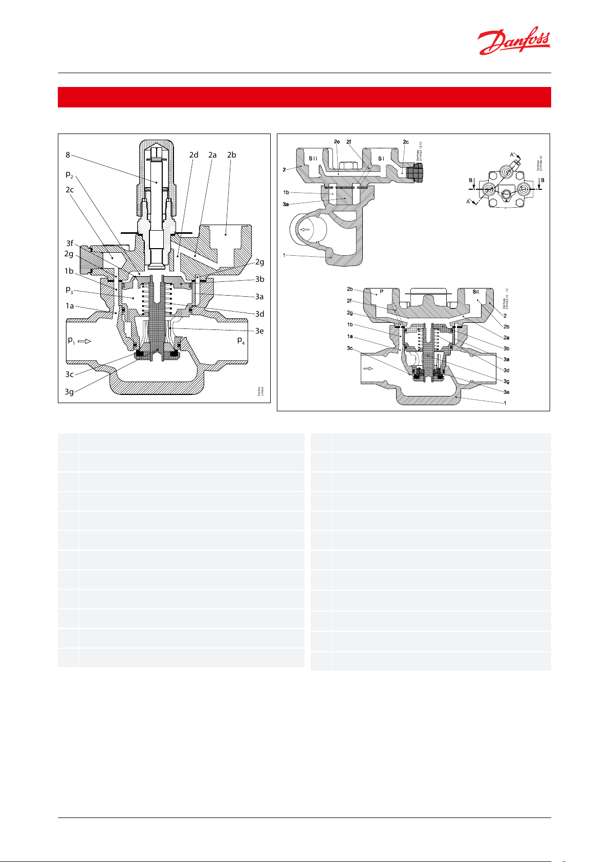
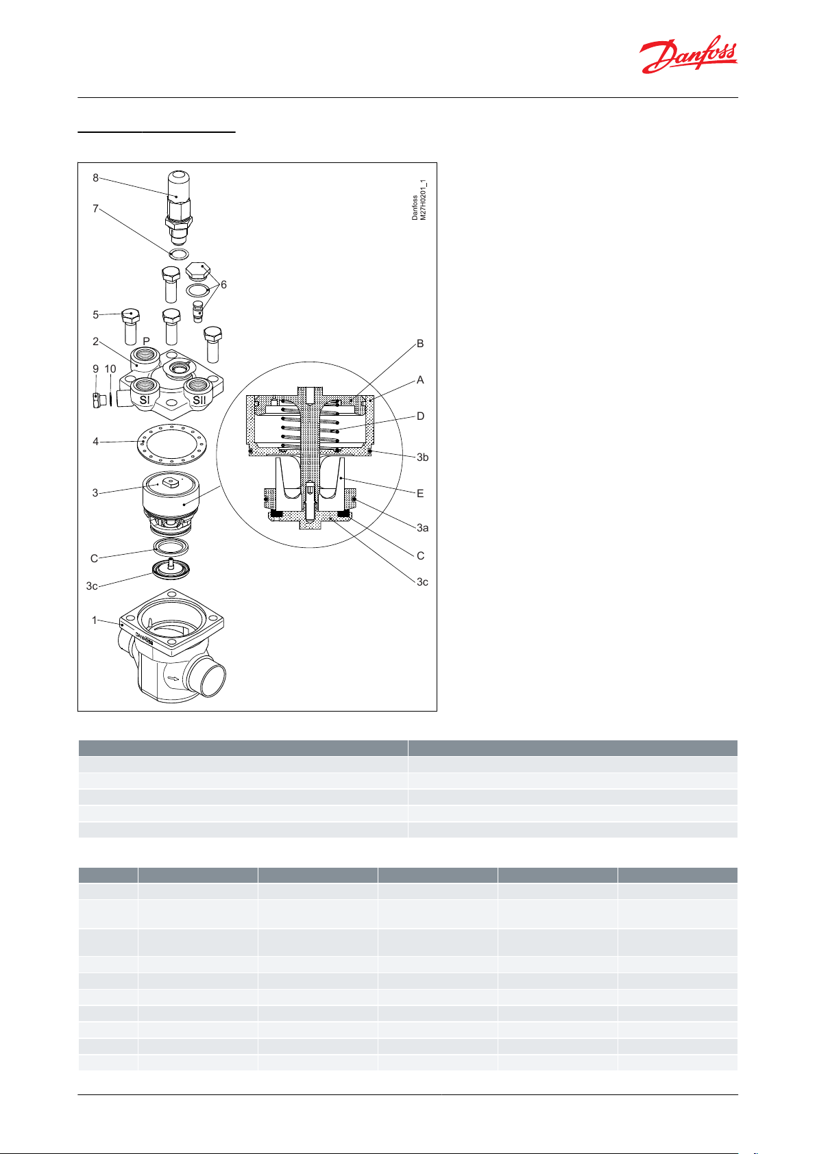
8
p
2
2c
3f
2g
1b
p
3
1a
3c
3g
p
1
p
4
2d 2a 2b
Danfoss
27H436
2g
3b
3a
3d
3e
11a1b22a2b2c2d2e2f2g33a3b3c3d3e3f3g
p1p2p3p
4
8
Body
Pilot channel to inlet side
Circular gap between house and module
Top cover
Pilot channels in top cover
Pilot insertion hole
Pressure gauge connection
Piston top inlet channel
Cross channel SI to SII
Inlet channel
Circular groove
Function module
Cylinder
Piston
Valve plate
Spring
Cone
Equalisation orice
Piston rod
Inlet pressure
Pressure on piston
Pressure underneath piston
Outlet pressure
Manual operating spindle
Pilot-operated servo valve, type ICS
Functions
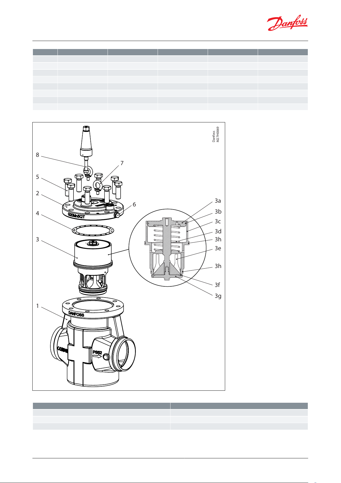
Figure 1: ICS 1 Pilot
Figure 2: ICS 3 Pilots
ICS 1 Pilot and ICS 3 Pilot
The ICS main valve is a pilot operated valve. The types of pilot valves used determine the function. The ICS main
valve with pilot valve(s) controls refrigerant ow
by modulation or on/o in accordance with the pilot valve and
main valve status. The manual spindle can be used to open the valve plate.
The opening degree of the main valve is determined by the pressure dierence (dierential pressure) between
pressure p2, which acts on top of the servo piston (3b), and pressure p3, which acts on the underside of the servo
piston.
If this pressure dierence is 0, the main valve will be fully closed.
© Danfoss | Climate Solutions | 2022.04 AI241186442033en-001301 | 3
Page 4

Pilot-operated servo valve, type ICS
If the pressure dierence is 0.2 bar (3 psi) or greater, the main valve will be fully open. At pressure
dierences (p2 -
p3) between 0.07 bar (1 psi) and 0.2 bar (3 psi), the degree of opening will be correspondingly proportional.
The port of the throttle cone (3e) is V-shaped, which provide good regulation characteristic to pilot operated main
valves even at low loads. P3 pressure is equal to the valve outlet pressure (P4), due to a clearance between the piston
rod (3g) and the function module. The opening degree of the ICS valve is therefore controlled by the application of
P2 pressure acting on top of the servo piston, which is equal to or greater than valve outlet pressure (P4).
p2 = p4 ~ closed
p2 = p4 + 0.2 bar (3 psi)~ fully open
p4 ≤ p2 ≤ p4 + 0.2 bar (3 psi) ~ proportional degree of opening.
The maximum pressure (p2) can act on the top of the servo piston (3b). p2 normally corresponds to the pressure, p1 ICS main valve inlet pressure. Inlet pressure p1 is led, via the drilled channels (1a, 1b, 2f, 2b (pilot), 2a, 2d) in the valve
body (1) and cover (2) through the individual pilot valves and onto the top of the servo piston (3b).
The degree of opening of the individual pilot valves determines the magnitude of pressure p2 and thus the degree
of opening of the main valve. The equalisation hole (3f) in the servo piston (3b) ensures that pressure p2 is balanced
in accordance with the degree of opening of the pilot valve.
NOTE:
When ICS valves with 3 pilot ports are used with external pressure connector (Figure 2: ICS 3 Pilots, pos. 61), the
valve port inlet pressure will be isolated.
The ICS can be tted with just a single screwed-in pilot valve or external pilot connection. The degree of opening of
the main valve will be in accordance with the control status of the pilot valve or external pilot ow control.
ICS main valve with one pilot connection is fully closed when the pilot valve is fully closed and fully open when the
pilot valve is fully open. Otherwise the degree of opening of the main valve is proportional to the degree of opening
of the pilot valve.
The ICS 3 pilot version can be tted with one, two, or three pilot valves so that up to three regulating functions are
possible. If the external pilot connection is used, more functions can be added.
In the ICS three pilot version, the pilot ports are related as follows:
• The pilot valves tted in ports SI and SII are connected in series.
• The ICS 3 pilot operated main valve will be fully closed if just one of the series-connected pilot valves is closed. The
main valve can only open if both pilot valves are open at the same time.
• The pilot valve tted in port P is connected in parallel to the pilot valves in ports SI and SII.
The ICS valve will be fully open if the pilot valve in P is fully open, irrespective of the degree of opening of pilot
valves SI and SII.
The ICS valve will be fully closed if the pilot valve in P is fully closed and at least one of the valves in SI or SII is fully
closed at the same time. The relation between the pilot valves in ports SI, SII and P is shown in the table on the next
page.
If the ICS is not tted with three pilot valves, the unused port(s) must be sealed with a blanking plug. If the blanking
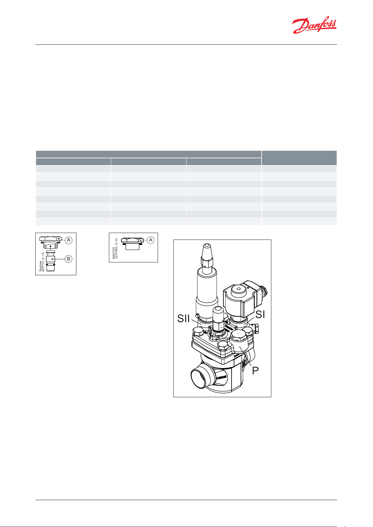
plug is tted as an assembled unit, A + B, the channels from the specic port will be closed. (See illustration below)
If only the top part, A, of the plug is tted, the channels from the ports in question will be open. If the degree of
opening of the ICS main valve is not to be a function of the main valve inlet pressure, or if more than three
regulating functions are required, ports SI, SII or P can be tted with a nipple for the connection of external pilot
pressure. This applies to all ICS versions.
The pressure to which the external pilot line is connected will then determine pressure p2 on top of the servo
piston. The pilot valves tted in that external pilot line will determine the main valve function. Pilot valves installed
in external lines must be mounted in a type CVH housing.
Depending on the function of the pilot valves, the ICS regulating characteristic becomes:
© Danfoss | Climate Solutions | 2022.04
AI241186442033en-001301 | 4
Page 5
A
B
P
SI
SII
Pilot valve port
ICS valve
SI
SII
P
Open
Open
Closed
Open
Open
Open
Open
Open
Open
Closed
Closed
Closed
Open
Closed
Open
Open
Closed
Open
Closed
Closed
Closed
Open
Open
Open
Closed
Closed
Closed
Closed
Closed
Closed
Open
Open
Pilot-operated servo valve, type ICS
• on/o
• proportional
• integral or
• cascade.
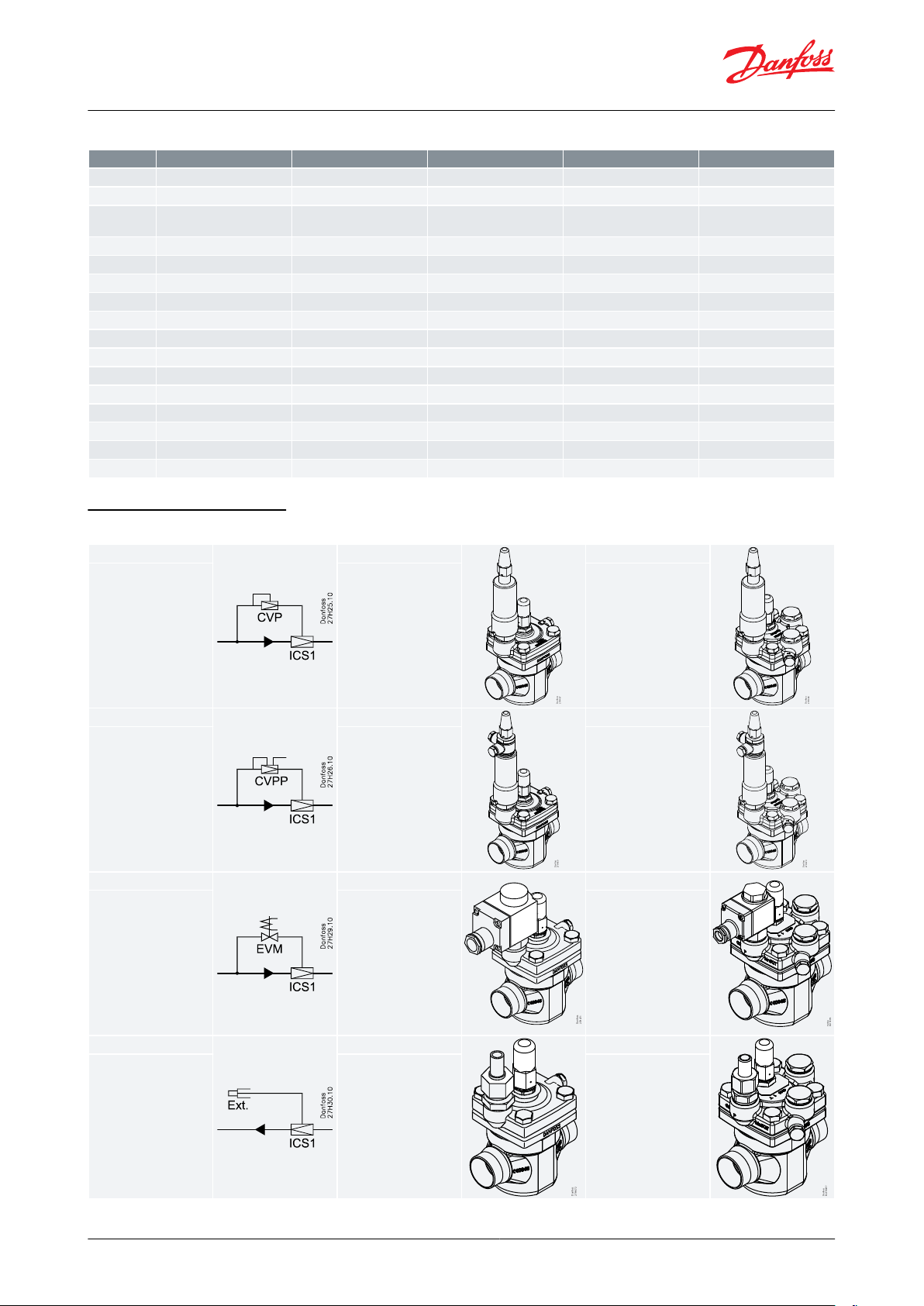
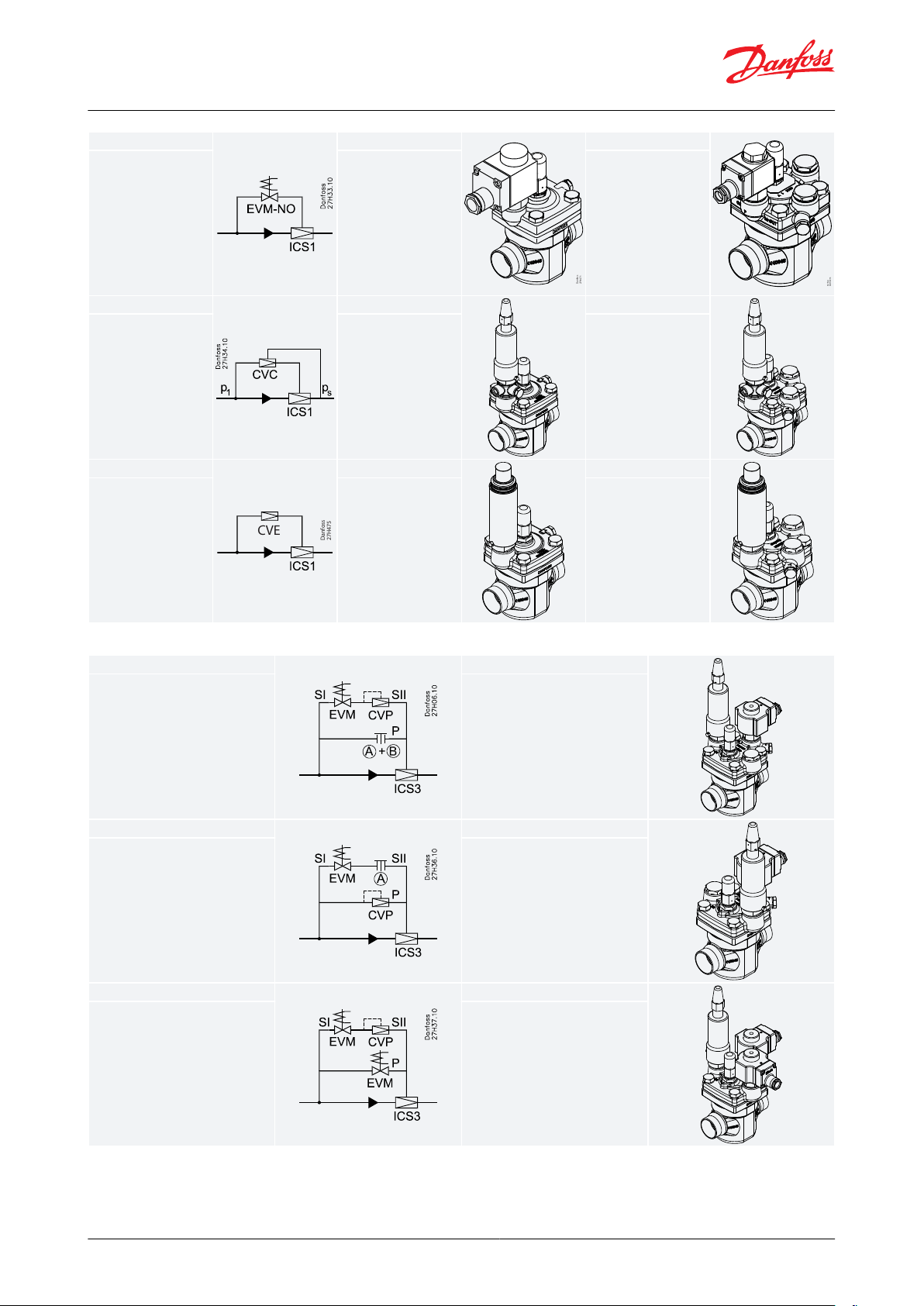
ICS main valves ar
e therefore especially suitable for all forms of temperature and pressure regulating systems.
An overview of the types of pilot valves available can be found in the literature “Pilot valves for operated main
valves” (AI248786497190).
On the following pages, a number of conguration examples can be found. These are only for explanatory purpose.
However, by using the literature regarding pilot valves these examples are easier to comprehend.
Table 1: Pilot valve port
Figure 3: Blanking plug A + B
Figure 4: Blanking plug AAFigure 5: Example (ICS with 3 pilot
valves)
© Danfoss | Climate Solutions | 2022.04 AI241186442033en-001301 | 5
Page 6

Pilot-operated servo valve, type ICS
Media
Refrigerants
Applicable to HCFC, HFC, R717(
Use with ammable hydrocarbons cannot be recommended; please contact Danfoss.
Surface protection ICS 25-150: The external surface is zinc-chromated to provide good corrosion protection.
Ammonia) and R744 (CO2).
New refrigerants
Danfoss products are continually evaluated for use with new refrigerants depending on market requirements.
When a refrigerant is approved for use by Danfoss, it is added to the relevant portfolio, and the R number of the
refrigerant (e.g. R513A) will be added to the technical data of the code number. Therefore, products for specic
refrigerants are best checked at store.danfoss.com/en/
, or by contacting your local Danfoss representative.
© Danfoss | Climate Solutions | 2022.04 AI241186442033en-001301 | 6
Page 7

Pilot-operated servo valve, type ICS
Product specication
Design
ICS valves ar
dierence is 0 bar /0 psi, the ICS valve will be closed. If the pressure dierence is 0.2 bar /3 psi or more, the ICS valve
will be fully open. At pressure dierences between 0.07 bar /1 psi and 0.2 bar /3 psi, the opening degree will be
correspondingly proportional.
The ICS is available for use with either one or three pilot valves.
Two of the three pilot pressure connections (S1 and S2) are connected in series whilst the third (P) is connected in
parallel to S1 and S2. This allows dierent combinations of pilot valves to be used, thus providing numerous
variations in control functions.
Valve body and top cover material Low temperature steel
e designed as pilot operated valves requiring minimal pressure dierential to open. If the pressure
Pressure and temperature range
Temperature range
-60 °C /+120 °C (-76 °F /+248 °F).
Pressure range
The valve is designed for: Max. working pressure: 52 bar (754 psig)
Surface protection
ICS 25-150: The external surface is zinc-chromated to provide good corrosion protection.
Opening
Fully open: Min. 0.2 bar (min. 3 psig); Max. Opening Pressure Dierential (MOPD), solenoid valves only - at nominal
conditions.
dierential pressure:
• 10 W a.c. up to 21 bar (305 psi)
• 20 W a.c. up to 40 bar (580 psi)
© Danfoss | Climate Solutions | 2022.04
AI241186442033en-001301 | 7
Page 8
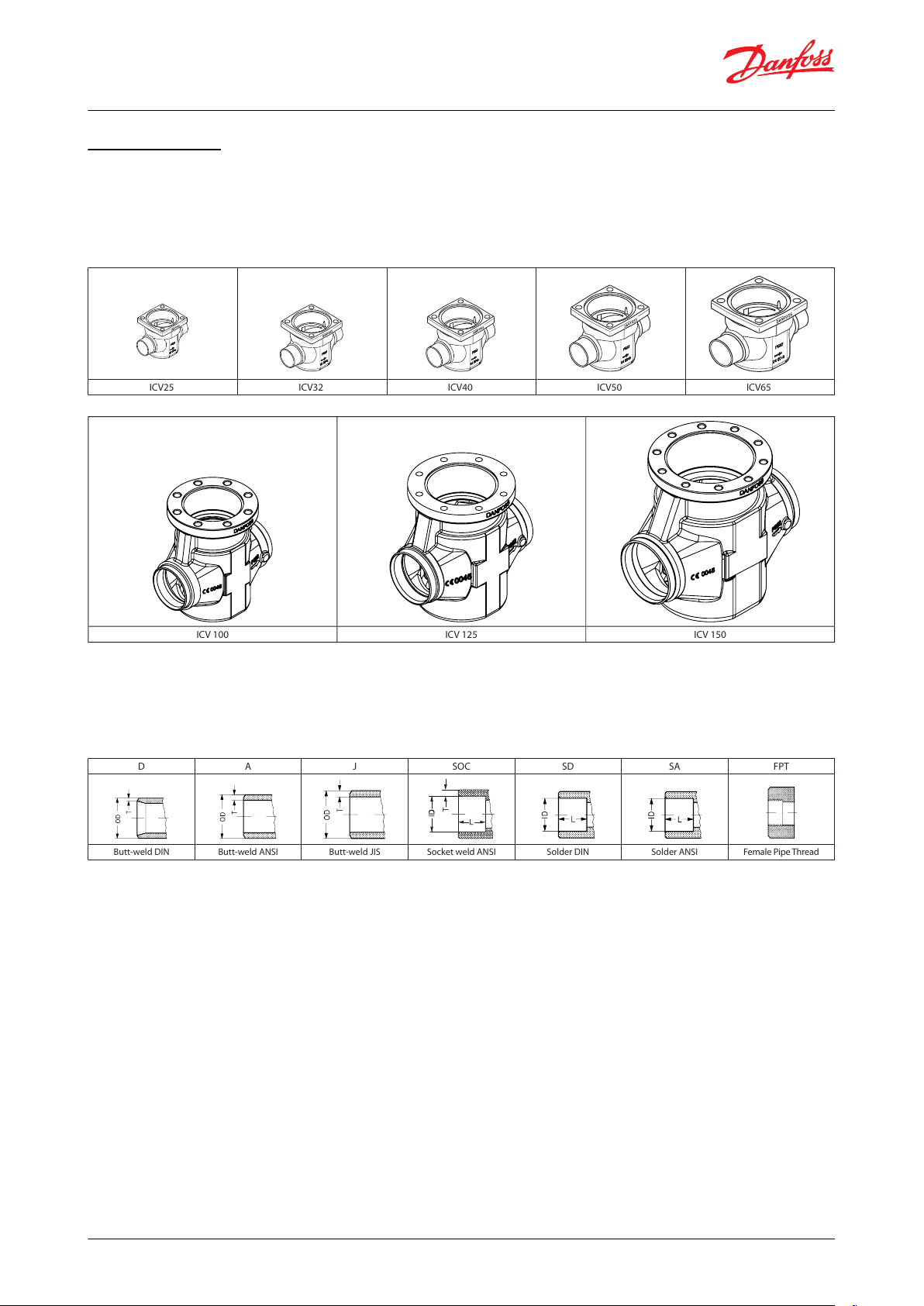
ICV25 ICV32 ICV40 ICV50 ICV65
ICV 100 ICV 125 ICV 150
D A J SOC SD SA FPT
Butt-weld DIN Butt-weld ANSI Butt-weld JIS Socket weld ANSI Solder DIN Solder ANSI Female Pipe Thread
Pilot-operated servo valve, type ICS
The ICS Concept
The ICS conc
ept is developed around a modular principle. This gives the possibility of combining function modules
and top covers with special valve body size that is available in a variety of connection possibilities.
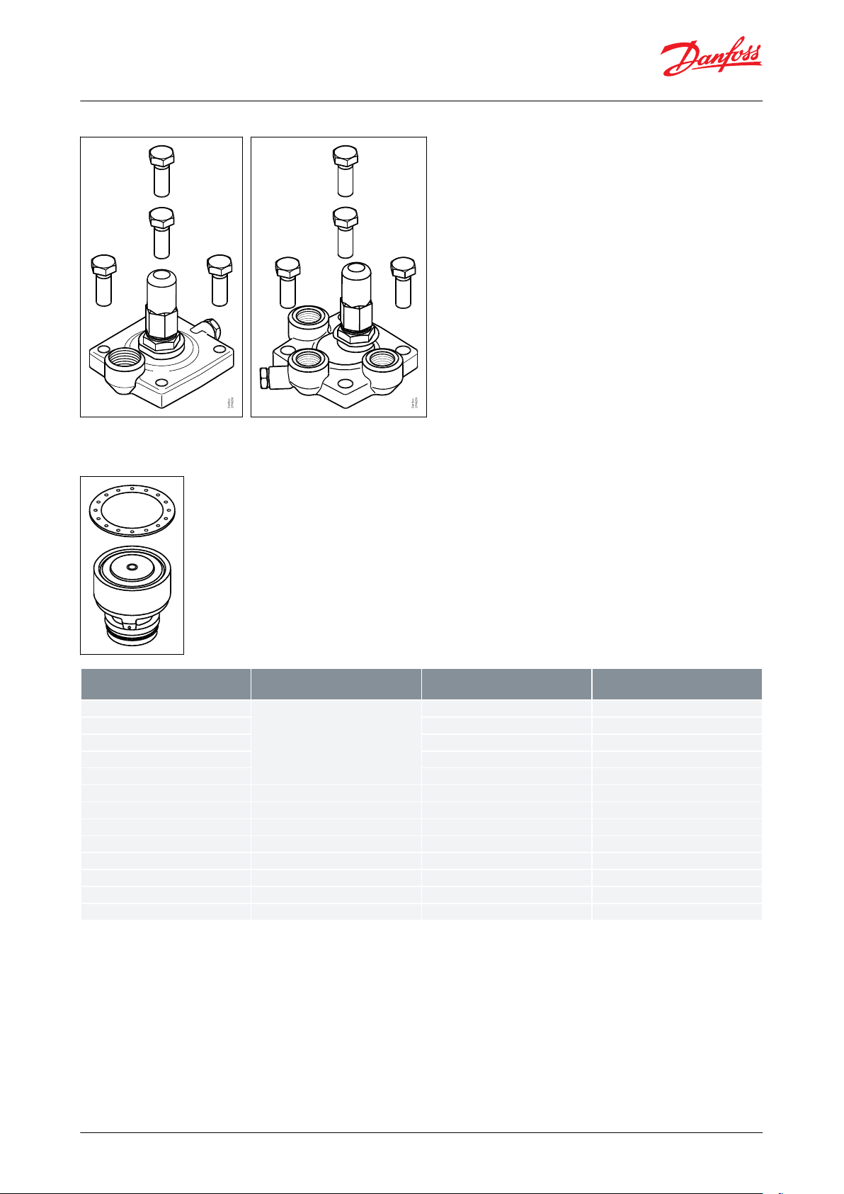
There are eight valve bodies available.
Figure 6: Valve bodies
Valve bodies in the sizes ICV 20-ICV65 are available with a range of undersizes through oversized connection sizes
and types.
V 100 - ICV 150 are available in butt-weld DIN and butt-weld ANSI nominal sizes
IC
Figure 7: Valve body in sizes
Each valve body may be tted with a 1 pilot or 3 pilot top cover.
© Danfoss | Climate Solutions | 2022.04
AI241186442033en-001301 | 8
Page 9
Danfoss
27H8258
Danfoss
27H8259
Type
Valve body size
K
v
(m3/h)
C
v
(USgal/min)
ICS 25-5
25
1.7
2.0
ICS 25-10
3.5
4.1
ICS 25-15
6.0
7.0
ICS 25-20
8
9.3
ICS 25-25
11.5
13.3
ICS 32
321720
ICS 40
402731
ICS 50
504451
ICS 65
657081
ICS 80
808598
ICS 100
100
142
165
ICS 125
125
207
240
ICS 150
150
354
410
Pilot-operated servo valve, type ICS
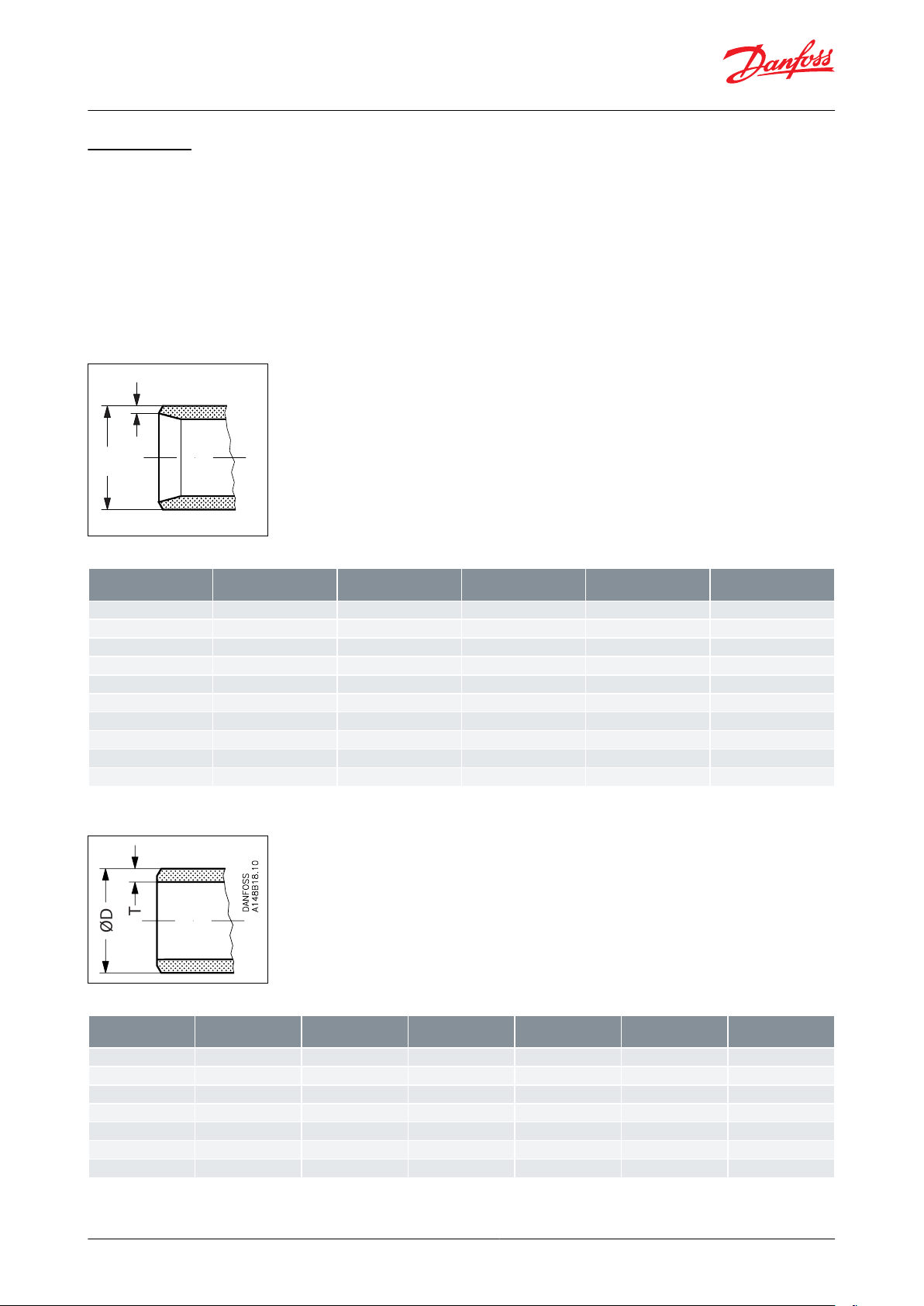
Figure 8: 1 pilot top cover
Figure 9: 3 pilot top cover
In ICS, multiple inserts (function modules) are available to give dierent
Figure 10: ICS function modules
capacities.
© Danfoss | Climate Solutions | 2022.04 AI241186442033en-001301 | 9
Page 10
T
ØD
Danfoss
A148B15.10
SizemmSize
in.ODmmTmmODin.Tin.
20
(¾)
26.9
2.3
1.059
0.09125(1)
33.7
2.6
1.327
0.10332(1¼)
42.4
2.6
1.669
0.10240(1½)
48.3
2.6
1.902
0.103
50
(2)
60.3
2.9
2.37
0.11
65
(2½)
76.1
2.930.1180(3)
88.9
3.2
3.50
0.13
100
(4)
114.3
3.6
4.5
0.14
125
(5)
140.745.5
0.16
150
(6)
168.3
6.3
6.6
0.25
T
ØD
SizemmSize
in.ODmmTmmODin.Tin.
Schedule
(20)¾26.9
4.0
1.059
0.15880(25)133.7
4.6
1.327
0.18180(32)1¼42.4
4.9
1.669
0.19380(40)1½48.3
5.1
1.902
0.201
80
(50)260.3
3.9
2.37
0.15
40
(65)2½73.0
5.2
2.87
0.2040(80)388.9
5.5
3.50
0.22
40
Pilot-operated servo valve, type ICS
Connections
There is a v
ery wide range of connection types available with ICS valves:
• D: Butt weld, DIN (2448)
• A: Butt weld, ANSI (B 36.10)
• J: Butt weld, JIS (B S 602)
• SOC: Socket weld, ANSI (B 16.11)
• SD: Solder connection, DIN (2856)
• SA: Solder connection, ANSI (B 16.22)
• FPT: Female pipe thread (ANSI/ASME B 1.20.1)
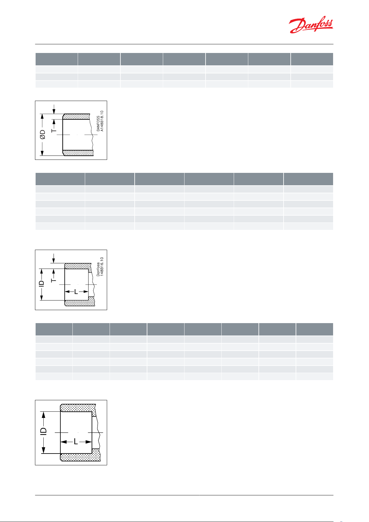
Figure 11: D: Butt-weld
DIN (2448)
Table 2: Butt-weld DIN
Figure 12: A: Butt-weld
ANSI (B 36.10)
Table 3: Butt-weld ANSI
© Danfoss | Climate Solutions | 2022.04
AI241186442033en-001301 | 10
Page 11
SizemmSize
in.ODmmTmmODin.Tin.
Schedule
(100)4114.364.5
0.24
(125)5140.7
6.5
5.5
0.26
(150)6168.3
7.1
6.6
0.28
T
ØD
SizemmSize
in.ODmmTmmODin.Tin.
(20)¾26.9
4.0
1.059
0.158
(25)133.7
4.6
1.327
0.181
(32)1¼42.4
4.9
1.669
0.193
(40)1½48.3
5.1
1.902
0.201
(50)260.3
3.9
2.37
0.15
(65)2½76.3
5.2
3.0
0.20
SizemmSize
in.ODmmTmmODin.Tin.LmmLin.
(20)¾27.2
4.6
1.071
0.181130.51
(25)133.9
7.2
1.335
0.284130.51
(32)1¼42.7
6.1
1.743
0.240130.51
(40)1½48.8
6.6
1.921
0.260130.51
(50)261.2
6.2
2.41
0.24160.63
(65)2½74
8.8
2.91
0.344160.63
L
ID
Pilot-operated servo valve, type ICS
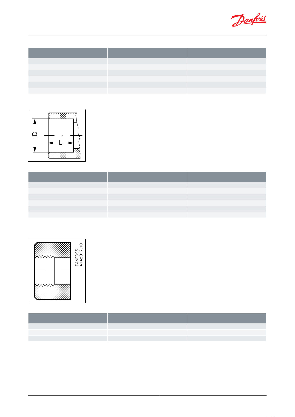
Figure 13: J: Butt-weld JIS
Table 4: Butt-weld JIS
Figure 14: SOC: Socket
welding ANSI (B 16.11)
Table 5: Socket welding ANSI
Figure 15: SD: Soldering
(DIN 2856)
© Danfoss | Climate Solutions | 2022.04 AI241186442033en-001301 | 11
Page 12
SizemmIDmmL
mm
22
22.08
16.52828.082635
35.072542
42.07
28
54
54.09
33
76
76.1
33
L
ID
Size
in.ODin.Lin.
⅞
0.875
0.6501⅛1.125
1.0241⅜1.375
1.0241⅝1.625
1.102
2⅛
2.125
1.300
2⅝
2.625
1.300
SizemmSize
in.
Inside pipe thread
(20)
¾
(¾ × 14 NPT)
(25)
1
(1 × 11.5 NPT)
(32)
1¼
(1¼ × 11.5 NPT)
Pilot-operated servo valve, type ICS
Table 6: SD: Soldering DIN
Figure 16: SA: Soldering
(ANSI B 16.22)
Table 7: Socket welding ANSI
Figure 17: FPT: Female
ead
pipe thr
ANSI/ASME B
, (
1.20.1)
Table 8: Socket welding ANSI
© Danfoss | Climate Solutions | 2022.04
AI241186442033en-001301 | 12
Page 13
B
A
D
3b
E
3a
C
3c
8
7
5
2
9
10
4
6
P
3
C
3c
1
Type
Screw
ICS 25
M12 × 30 A2-70 DIN 933
ICS 32
M14 × 35 A2-70 DIN 933
ICS 40
M14 × 40 A2-70 DIN 933
ICS 50
M16 × 40 A2-70 DIN 933
ICS 65
M16 × 50 A2-70 DIN 933
No.
Part
Material
EN
ASTM
JIS
1
Body
Low temperature steel
G20Mn5QT, EN 10213-3
LCC A352
SCPL1 G5151
2
Top cover
Low temperature steel
G20Mn5QT, EN 10213-3
P285QH+QT 10222-4
LCC A352
LF2, A350
SCPL1 G5151
3
Function module (assembled)3ao-ring
Cloroprene (Neoprene)
3b
o-ring
Cloroprene (Neoprene)
3c
Washer plate
Steel
A
Cylinder
SteelBPiston
SteelCValve plate
PTFE
D
Spring
Steel
Pilot-operated servo valve, type ICS
Material specication
Figure 18: ICS 25, 32, 40, 50, 65
Table 9: Type and size of Bolt (pos. 5)
Table 10: Material and parts list (ICS 25, 32, 40, 50, 65)
© Danfoss | Climate Solutions | 2022.04 AI241186442033en-001301 | 13
Page 14
No.
Part
Material
EN
ASTM
JIS
E
Cone
Steel4Gasket
Fiber, non-asbestos
5
Bolts
Stainless steel
A2-70, EN 1515-1
Grade B8 A320
A2-70, B 1054
6
Plug
Steel7Gasket
Aluminium
8
Manual operating spindle
Steel
9
Plug
Steel10Gasket
Aluminium
1
2
3
3a
Danfoss
M27H0069
3b
3c
3d
3e
3f
3g
3h
3h
4
5
6
7
8
Type
Screw
ICS 100
M20 × 60 A2-70 DIN 933
ICS 125
M20 × 60 A2-70 DIN 933
ICS 150
M20 × 70 A2-70 DIN 933
Pilot-operated servo valve, type ICS
Figure 19: ICS 100, 125, 150
Table 11: Type and size of Bolt (pos. 5)
© Danfoss | Climate Solutions | 2022.04
AI241186442033en-001301 | 14
Page 15
No.
Part
Material
EN
ASTM
JIS
1
Body
Low temperature steel
G20Mn5QT, EN 10213-3
LCC A352
SCPL1 G5151
2
Top cover
Low temperature steel
G20Mn5QT, EN 10213-3
LCC A352
SCPL1 G5151
3
Function module (assembled)3aPiston/rod
Stainless steel / steel
3b
Piston ring
Steel3cInsert
Steel
3d
Spring
Steel3eCone
Stainless steel / steel
3f
Teon plate
Teon unlled
3g
Washer plate
PTFE3hO-ring
Cloroprene (Neoprene)
4
Gasket
Fiber, non-asbestos
5
Bolts
Stainless steel
A2-70, EN 1515-1
Grade B8 A320
A2-70, B 1054
6
Plug
Steel7Eye bolt
Galvanized steel
8
Manual operating spindle
Steel
Example no. 1-1
Products
Danfoss
27H467
Products
Danfoss
27H468
Constant pressure
regulation
• CVP
-L (-0.66 to 7 bar g)
(19.5 in. Hg to 102
psig)
• CVP-M (4 to 28 bar g)
(58 to 406 psig)
• CVP-H (25 to 52 bar g)
(363 to 754 psig)
1 × ICS 1 Pilot
1 × CVP-L/M/H
1 × ICS 3 Pilots
1 × CVP-L/M/H
2 × Blank
ing plugs
SI: A + B
SII: A
Example no. 1-2
Products
Danfoss
27H469
Products
Danfoss
27H470
Dierential pressure r
egu-
lation
• CVPP-L (0.66 to 7 bar
g) (19.5 in. Hg to 102
psig)
• CVPP-M (4 to 28 bar g)
(58 to 406 psig)
1 × ICS 1 Pilot
1 × CVPP-L/M
1 × ICS 3 Pilots
1 × CVPP-L/M
2 × Blank
ing plugs
SI: A + B
SII: A
Example no. 1-3
Products
Danfoss
27H471
Products
Danfoss
M27H0076
On/o regulation (solenoid valv
e)
1 × ICS 1 Pilot
1 × EVM
1 × coil
1 × ICS 3 Pilots
1 × EVM
1 × coil
2 × Blank
ing plugs
SI: A + B
SII: A
Example no. 1-4
Products
Danfoss
27H472
Products
Danfoss
M27H0077
Regulation with external
contr
ol pressure
1 × ICS 1 Pilot
1 × nipple for ex
ternal
control pressure
1 × ICS 3 Pilots
1 × nipple for ex
ternal
control pressure
2 × Blanking plugs
SI: A + B
SII: A
Pilot-operated servo valve, type ICS
Table 12: Material and parts list (ICS 100, 125, 150)
Conguration examples
Table 13: Example no. 1
© Danfoss | Climate Solutions | 2022.04 AI241186442033en-001301 | 15
Page 16
Example no. 1-5
Products
Danfoss
27H471
Products
Danfoss
M27H0076
On/o regulation (solenoid valv
e)
1 × ICS 1 Pilot
1 × EVM-NO
(12 W c
oil)
1 × ICS 3 Pilots
1 × EVM-NO (12 W c
oil)
2 × Blanking plugs
SI: A + B
SII: A
Example no. 1-6
Products
Products
Crankcase pressure regulation. (Max. suction pr
es-
sure regulation)
• -0.45 to 7 bar g (13.3
in. Hg to 102 psig)
1 × ICS 1 Pilot
1 × CVC-L
1 × ICS 3 Pilots
1 × CVC-L
2 × Blanking plugs
SI: A + B
SII: A
Example no. 1-7
CVE
Danfoss
27H475
Products
Products
Electronically controlled
media temperatur
e regu-
lation
• -0.66 to 8 bar g (19.5
in. Hg to 116 psig)
1 × ICS 1 Pilot
1 × CVE
1 × ICS 3 Pilots
1 × CVE
2 × Blanking plugs
SI: A + B
SII: A
Example no. 2-1
Products
Constant pressure regulation combined
with electrical shut
o
• -0.66 bar to 7 bar (19.5 in. Hg to 102
psig)
1 × ICS 3 Pilots
1 × blanking plug (A + B)
1 × C
VP-L
1 × EVM
1 × coil
Example no. 2-2
Products
Constant pressure regulation combined
with electrical wide open
1 × ICS 3 Pilots
1 × blanking plug (A
)
1 × CVP-L
1 × EVM
Example no. 2-3
Products
Constant pressure regulation combined
with electrical shut
o and wide open
• -0.66 bar to 7 bar (19.5 in. Hg to 102
psig)
1 × ICS 3 Pilots
1 × CVP-L
2 × E
VM
2 × coils
Pilot-operated servo valve, type ICS
Table 14: Example no. 2
© Danfoss | Climate Solutions | 2022.04
AI241186442033en-001301 | 16
Page 17

Example no. 2-4
Products
Constant pressure regulation with
change-o
ver between two preset evap-
orating pressures
• -0.66 bar to 7 bar (19.5 in. Hg to 102
psig)
1 × ICS 3 Pilots
2 × CVP-L
1 × E
VM
1 × coil
Example no. 2-5
Products
External control pressure with electrical
shut o combined with constan
t pres-
sure regulation
• -0.66 bar to 7 bar (19.5 in. Hg to 102
psig)
1 × ICS 3 Pilots
1 × Nipple for e
xternal
control pressure
1 × CVP-L
1 × EVM
1 × Coil
Example no. 2-6
Products
Constant pressure regulation with external c
ontrol pressure combined with
electrical wide open
• -0.66 bar to 7 bar (19.5 in. Hg to 102
psig)
1 × ICS 3 Pilots
1 × Nipple for e
xternal
control pressure
1 × CVP-L
1 × EVM
1 × Coil
Example no. 2-7
Products
Constant pressure regulation with electrical shut o
combined with external
control pressure
• -0.66 bar to 7 bar (19.5 in. Hg to 102
psig)
1 × ICS 3 Pilots
1 × Nipple for e
xternal
control pressure
1 × CVP-L
1 × EVM
1 × Coil
Example no. 2-8
Products
Solenoid valve with external control
pressure f
or small pressure drops
1 × ICS 3
1 × Blanking plug (A + B)
1 × N
ipple for external
control pressure
1 × EVM
1 × Coil
Example no. 2-9
Products
Dierential pressure r
egulation com-
bined with electrical shut o
• CVPP-L (0.66 bar to 7 bar ) (19.5 in.
Hg to 102 psig)
1 × ICS 3
1 × Blanking plug (A + B)
1 × C
VPP-L
1 × EVM
1 × Coil
Pilot-operated servo valve, type ICS
© Danfoss | Climate Solutions | 2022.04 AI241186442033en-001301 | 17
Page 18

Example no. 2-10
Products
Dierential pressure r
egulation com-
bined with electrical wide open
• CVPP-L (0.66 bar to 7 bar) (19.5 in.
Hg to 102 psig)
1 × ICS 3 Pilots
1 × Blanking plug (A
)
1 × CVPP-L
1 × EVM
1 × Coil
Example no. 2-11
Products
Dierential pressure r
egulation combined with electrical wide open and
shut o
• CVPP-L (0.66 bar to 7 bar) (19.5 in.
Hg to 102 psig)
1 × ICS 3 Pilots
1 × CVPP-L
2 × E
VM
2 × Coils
Example no. 2-12
Danfoss
27H492
Products
Constant pressure regulation combined
with electrical shut
o
• CVP-L (-0.66 bar to 7 bar) (19.5 in. Hg
to 102 psig)
• CVP-M (4 bar to 28 bar) (58 to 406
psig)
• CVP-H (25 bar to 52 bar) (363 to 754
psig)
1 × ICS 3 Pilots
1 × Blanking plug (A + B)
1 × C
VP-L/M/H
1 × EVM
1 × Coil
Example no. 2-13
Danfoss
27H493
Products
Constant pressure regulation combined
with electrical wide open
•
CVP-L (-0.66 bar to 7 bar) (19.5 in. Hg
to 102 psig)
• CVP-M (4 bar to 28 bar) (58 to 406
psig)
• CVP-H (25 bar to 52 bar) (363 to 754
psig)
1 × ICS 3 Pilots
1 × Blanking plug (A
)
1 × CVP-L/M/H
1 × EVM
1 × Coil
Example no. 2-14
Danfoss
27H494
Products
Danfoss
27H491
Constant pressure regulation combined
with electrical shut
o and wide open
• CVP-L (-0.66 bar to 7 bar) (19.5 in. Hg
to 102 psig)
• CVP-M (4 bar to 28 bar) (58 to 406
psig)
• CVP-H (25 bar to 52 bar) (363 to 754
psig)
1 × ICS 3 Pilots
1 × CVP-L/M/H
2 × E
VM
2 × Coils
Example no. 2-15
Danfoss
27H495
Products
Danfoss
27H500
Constant pressure regulation with
change-o
ver between two preset evap-
orating pressures
• CVP-L (-0.66 bar to 7 bar) (19.5 in. Hg
to 102 psig)
• CVP-M (4 bar to 28 bar) (58 to 406
psig)
• CVP-H (25 bar to 52 bar) (363 to 754
psig)
1 × ICS 3 Pilots
2 × CVP-L/M/H
1 × E
VM
1 × Coil
Pilot-operated servo valve, type ICS
© Danfoss | Climate Solutions | 2022.04
AI241186442033en-001301 | 18
Page 19

Example no. 2-16
Danfoss
27H496
Products
Danfoss
27H501
Dierential pressure r
egulation com-
bined with electrical shut o
• CVPP-L (-0.66 bar to 7 bar) (19.5 in.
Hg to 102 psig)
• CVPP-M (4 bar to 28 bar) (58 to 406
psig)
1 × ICS 3 Pilots
1 × Blanking plug (A + B)
1 × C
VPP-L/M
1 × EVM
1 × Coil
Example no. 2-17
Danfoss
27H497
Products
Danfoss
27H502
Dierential pressure r
egulation com-
bined with electrical wide open
• CVPP-L (-0.66 bar to 7 bar) (19.5 in.
Hg to 102 psig)
• CVPP-M (4 bar to 28 bar) (58 to 406
psig)
1 × ICS 3 Pilots
1 × Blanking plug (A
)
1 × CVPP-L/M
1 × EVM
1 × Coil
Example no. 2-18
Danfoss
27H498
Products
Danfoss
27H503
Dierential pressure r
egulation combined with electrical wide open and
shut o
• CVPP-L (-0.66 bar to 7 bar) (19.5 in.
Hg to 102 psig)
• CVPP-M (4 bar to 28 bar) (58 to 406
psig)
1 × ICS 3 Pilots
1 × CVPP-L/M
2 × E
VM
2 × Coils
Example no. 2-19
Danfoss
27H499
Products
Danfoss
27H504
Constant pressure regulation combined
with electrical wide open and shut
o
• CVP-L (-0.66 bar to 7 bar) (19.5 in. Hg
to 102 psig)
• CVP-M (4 bar to 28 bar) (58 to 406
psig)
• CVP-H (25 bar to 52 bar) (363 to 754
psig)
1 × ICS 3 Pilots
1 × CVP-L/M/H
1 × E
VM
1 × EVM-NO (12 W coil)
2 × Coils
Example no. 2-20
Products
Danfoss
27H514
Crankcase pressure regulation (max.
suction pressur
e regulation) combined
with shut o
• -0.45 bar to 7 bar (13.3 in. Hg to 102
psig)
1 × ICS 3 Pilots
1 × Blanking plug (A + B)
1 × C
VC-L
1 × EVM
1 × Coil
Example no. 2-21
Products
Danfoss
27H511
Crankcase pressure regulation (max.
suction pressur
e regulation) combined
with evaporating pressure regulation
• -0.66 bar to 28 bar (19.5 in. Hg to
406 psig).
1 × ICS 3 Pilots
1 × Blanking plug (A + B)
1 × C
VC-L/M
1 × CVP-L/M
Pilot-operated servo valve, type ICS
© Danfoss | Climate Solutions | 2022.04 AI241186442033en-001301 | 19
Page 20

Example no. 2-22
Products
Danfoss
27H512
Crankcase pressure regulation (max.
suction pressur
e regulation) at low
pressure drops across the valve
• -0.45 bar to 7 bar (13.3 in. Hg to 102
psig)
1 × ICS 3 Pilots
1 × Blanking plug (A + B)
1 × N
ipple for external
control pressure
1 × CVC-L
Example no. 2-23
Products
Danfoss
27H513
Crankcase pressure regulation (max.
suction pressur
e regulation) combined
with constant pressure regulation and
electrical shut o.
• -0.66 bar to 7 bar (19.5 in. Hg to 102
psig).
1 × ICS 3 Pilots
1 × Blanking plug (A + B)
1 × N
ipple for external
control pressure
1 × CVP-L
1 × EVM
1 × Coil
2 × CVH
1 × CVC-L
Example no. 2-24
Products
Danfoss
27H514
Hot gas bypass regulation combined
with electrical shut
o
• -0.45 bar to 7 bar (13.3 in. Hg to 102
psig)
1 × ICS 3 Pilots
1 × Blanking plug (A + B)
1 × C
VC-L
1 × EVM
1 × Coil
Example no. 2-25
Danfoss
27H505
Products
Danfoss
27H515
Constant pressure regulation with electrical shut o
and protection against
high pressure when suction line is
closed
• -0.66 bar to 28 bar (19.5 in. Hg to
406 psig).
1 × ICS 3 Pilots
1 × CVP-L
1 × E
VM
1 × Coil
1 × CVP-M
Example no. 2-26
CVE
Danfoss
27H506
Products
Danfoss
27H516
Electronically controlled media temperature regulation c
ombined with electri-
cal shut o
• -1 bar to 8 bar (0 in. Hg to 116 psig).
1 × ICS 3 Pilots
1 × Blanking plug (A + B)
1 × C
VE
1 × EVM
1 × Coil
Example no. 2-27
CVE
Danfoss
27H506
Products
Electronically controlled media temperatur
e r
egulation c
ombined with electri-
cal shut o and wide open
• -1 bar to 8 bar (0 in. Hg to 116 psig).
1 × ICS 3 Pilots
1 × C
VE
2 × E
VM
2 × C
oils
Pilot-operated servo valve, type ICS
© Danfoss | Climate Solutions | 2022.04
AI241186442033en-001301 | 20
Page 21

Example no. 2-28
CVE
Danfoss
27H507
Products
Danfoss
27H518
Electronically controlled media temperature regulation c
ombined with electrical shut o and changeover to constant
pressure regulation
• -1 bar to 8 bar (0 in. Hg to 116 psig).
1 × ICS 3 Pilots
1 × CVQ
1 × CVP
-L
1 × EVM
1 × Coil
Example no. 2-29
CVE
Danfoss
27H508
Products
Danfoss
27H519
Electronically controlled media temperature regulation with lo
w evaporating
pressure protection combined with
wide open
• -1 bar to 8 bar (0 in. Hg to 116 psig).
1 × ICS 3 Pilots
1 × CVE
1 × CVP
-L
1 × EVM
1 × Coil
Example no. 2-30
CVE
Danfoss
27H509
Products
Danfoss
27H520
Electronically controlled media temperature regulation with lo
w evaporating
pressure protection combined with
changeover to constant pressure regulation
• -1 bar to 8 bar (0 in. Hg to 116 psig).
1 × ICS 3 Pilots
1 × CVE
2 × CVP
-L
Pilot-operated servo valve, type ICS
Valve selection based on capacity calculation
As for extended capacity calculations and valve selection based on capacities and refrigerants, please refer to
Coolselector®2. Rated and extended capacities are calculated with the Coolselector®2 calculation engine to ARI
standards with the ASEREP equations based on laboratory measurements of selected valves.
Download Coolselector®2 for free at coolselector.danfoss.com
.
© Danfoss | Climate Solutions | 2022.04
AI241186442033en-001301 | 21
Page 22

ICS 3 Pilots
ICS 1 pilot
Connection
H1H2H3H
4
L
L1L2B1B
2
Weight
ICS 1 Pilot
Weight
ICS 3
Pilots
20 D (¾ in.)
mm
in.371.46
145
5.71863.39602.36
135
5.31421.65150.59421.65873.43
3 kg
6.6 lb.
3.6 kg
7.92 lb.
25 D (1 in.)
mm
in.371.46
145
5.71863.39602.36
135
5.31421.65150.59421.65873.43
3 kg
6.6 lb.
3.6 kg
7.92 lb.
32 D (1¼ in.)
mm
in.371.46
145
5.71863.39602.36
135
5.31421.65150.59421.65873.43
3 kg
6.6 lb.
3.6 kg
7.92 lb.
40 D (1½ in.)
mm
in.371.46
145
5.71863.39602.36
135
5.31421.65150.59421.65873.43
3 kg
6.6 lb.
3.6 kg
7.92 lb.
20 A (¾ in.)
mm
in.371.46
145
5.71863.39602.36
135
5.31421.65150.59421.65873.43
3 kg
6.6 lb.
3.6 kg
7.92 lb.
25 A (1 in.)
mm
in.371.46
145
5.71863.39602.36
135
5.31421.65150.59421.65873.43
3 kg
6.6 lb.
3.6 kg
7.92 lb.
32 A (1¼ in.)
mm
in.371.46
145
5.71863.39602.36
135
5.31421.65150.59421.65873.43
3 kg
6.6 lb.
3.6 kg
7.92 lb.
20 SOC (¾ in.)
mm
in.371.46
145
5.71863.39602.36
135
5.31421.65150.59421.65873.43
3 kg
6.6 lb.
3.6 kg
7.92 lb.
25 SOC (1 in.)
mm
in.371.46
145
5.71863.39602.36
147
5.79421.65150.59421.65873.43
3 kg
6.6 lb.
3.6 kg
7.92 lb.
22 SD (⅞ in.)
mm
in.371.46
145
5.71863.39602.36
135
5.31421.65150.59421.65873.43
3 kg
6.6 lb.
3.6 kg
7.92 lb.
28 SD (1⅛ in.)
mm
in.371.46
145
5.71863.39602.36
147
5.78421.65150.59421.65873.43
3 kg
6.6 lb.
3.6 kg
7.92 lb.
22 SA (⅞ in.)
mm
in.371.46
145
5.71863.39602.36
135
5.31421.65150.59421.65873.43
3 kg
6.6 lb.
3.6 kg
7.92 lb.
28 SA (1⅛ in.)
mm
in.371.46
145
5.71863.39602.36
147
5.78421.65150.59421.65873.43
3 kg
6.6 lb.
3.6 kg
7.92 lb.
Pilot-operated servo valve, type ICS
Dimensions and weights
ICS 25-5 to ICS 25-25
e 20: Dimensions and weights - ICS 25-5 to ICS 25-25
Figur
Table 15: Connection type and Weight
© Danfoss | Climate Solutions | 2022.04
AI241186442033en-001301 | 22
Page 23

Connection
H1H2H3H
4
L
L1L2B1B
2
Weight
ICS 1 Pilot
Weight
ICS 3
Pilots
35 SA (1⅜ in.)
mm
in.371.46
145
5.71863.39602.36
147
5.78421.65150.59421.65873.43
3 kg
6.6 lb.
3.6 kg
7.92 lb.
20 FPT (¾ in.)
mm
in.371.46
145
5.71863.39602.36
135
5.31421.65150.59421.65873.43
3 kg
6.6 lb.
3.6 kg
7.92 lb.
25 FPT (1 in.)
mm
in.371.46
145
5.71863.39602.36
135
5.31421.65150.59421.65873.43
3 kg
6.6 lb.
3.6 kg
7.92 lb.
ICS 3 Pilots
ICS 1 pilot
Connection
H1H2H3H
4
L
L1L2B1B
2
Weight
ICS 1 Pilot
Weight
ICS 3
Pilots
32 D (1¼ in.)
mm
in.401.57
160
6.30
100
3.93742.91
145
5.71512.00150.59512.00873.43
4.5 kg
9.9 lb.
5 kg
11 lb.
40 D (1½ in.)
mm
in.401.57
160
6.30
100
3.93742.91
145
5.71512.00150.59512.00873.43
4.5 kg
9.9 lb.
5 kg
11 lb.
32 A (1¼ in.)
mm
in.401.57
160
6.30
100
3.93742.91
145
5.71512.00150.59512.00873.43
4.5 kg
9.9 lb.
5 kg
11 lb.
Pilot-operated servo valve, type ICS
NOTE:
Specied weights ar
e approximate values only.
D = Butt-weld DIN
A = Butt-weld ANSI
J = Butt-weld JIS
SOC = Socket weld ANSI
SD = Solder DIN
SA = Solder ANSI
FPT = Female Pipe Thread
ICS 32
Figure 21: ICS 32, Dimensions and weights
Table 16: Connection type and Weight
© Danfoss | Climate Solutions | 2022.04 AI241186442033en-001301 | 23
Page 24

Connection
H1H2H3H
4
L
L1L2B1B
2
Weight
ICS 1 Pilot
Weight
ICS 3
Pilots
40 A (1½ in.)
mm
in.401.57
160
6.30
100
3.93742.91
145
5.71512.00150.59512.00873.43
4.5 kg
9.9 lb.
5 kg
11 lb.
32 SOC (1¼ in.)
mm
in.401.57
160
6.30
100
3.93742.91
145
5.71512.00150.59512.00873.43
4.5 kg
9.9 lb.
5 kg
11 lb.
35 SD (1⅜ in. SA)
mm
in.401.57
160
6.30
100
3.93742.91
145
5.71512.00150.59512.00873.43
4.5 kg
9.9 lb.
5 kg
11 lb.
42 SD (1⅝ in.)
mm
in.401.57
160
6.30
100
3.93742.91
145
5.71512.00150.59512.00873.43
4.5 kg
9.9 lb.
5 kg
11 lb.
42 SA (1⅝ in.)
mm
in.401.57
160
6.30
100
3.93742.91
145
5.71512.00150.59512.00873.43
4.5 kg
9.9 lb.
5 kg
11 lb.
ICS 3 Pilots
ICS 1 pilot
Pilot-operated servo valve, type ICS
NOTE:
Specied weights ar
e approximate values only.
D = Butt-weld DIN
A = Butt-weld ANSI
J = Butt-weld JIS
SOC = Socket weld ANSI
SD = Solder DIN
SA = Solder ANSI
FPT = Female Pipe Thread
ICS 40
Figure 22: ICS 40, Dimensions and weights
© Danfoss | Climate Solutions | 2022.04
AI241186442033en-001301 | 24
Page 25

Connection
H1H2H3H
4
L
L1L2B1B
2
Weight
ICS 1 Pilot
Weight
ICS 3
Pilots
40 D (1½ in.)
mm
in.491.93
166
6.54
105
4.13783.07
160
6.30512.00150.59542.13873.43
5.9 kg
13.0 lb.
6.3 kg
13.9 lb.
50 D (2 in. )
mm
in.491.93
166
6.54
105
4.13783.07
180
7.09512.00150.59542.13873.43
5.9 kg
13.0 lb.
6.3 kg
13.9 lb.
40 A (1½ in.)
mm
in.491.93
166
6.54
105
4.13783.07
160
6.30512.00150.59542.13873.43
5.9 kg
13.0 lb.
6.3 kg
13.9 lb.
50 A (2 in.)
mm
in.491.93
166
6.54
105
4.13783.07
180
7.09512.00150.59542.13873.43
5.9 kg
13.0 lb.
6.3 kg
13.9 lb.
40 SOC (1½ in.)
mm
in.491.93
166
6.54
105
4.13783.07
180
7.09512.00150.59542.13873.43
5.9 kg
13.0 lb.
6.3 kg
13.9 lb.
42 SD (1⅝ in.)
mm
in.491.93
166
6.54
105
4.13783.07
180
7.09512.00150.59542.13873.43
5.9 kg
13.0 lb.
6.3 kg
13.9 lb.
42 SA (1⅝ in.)
mm
in.491.93
166
6.54
105
4.13783.07
180
7.09512.00150.59542.13873.43
5.9 kg
13.0 lb.
6.3 kg
13.9 lb.
ICS 3 Pilots
ICS 1 pilot
Pilot-operated servo valve, type ICS
Table 17: Connection type and Weight
NOTE:
Specied weights ar
e approximate values only.
D = Butt-weld DIN
A = Butt-weld ANSI
J = Butt-weld JIS
SOC = Socket weld ANSI
SD = Solder DIN
SA = Solder ANSI
FPT = Female Pipe Thread
ICS 50
Figure 23: ICS 50, Dimensions and weights
© Danfoss | Climate Solutions | 2022.04 AI241186442033en-001301 | 25
Page 26

Connection
H1H2H3H
4
L
L1L2B1B
2
Weight
ICS 1 Pilot
Weight
ICS 3
Pilots
50 D (2 in. )
mm
in.592.32
181
7.13
120
4.72933.66
200
7.87512.00150.59632.48913.58
8.9 kg
19.6 lb.
9.2 kg
20.2 lb.
65 D (2½ in.)
mm
in.592.32
181
7.13
120
4.72933.66
210
8.27512.00150.59632.48913.58
8.9 kg
19.6 lb.
9.2 kg
20.2 lb.
50 A (2 in.)
mm
in.592.32
181
7.13
120
4.72933.66
200
7.87512.00150.59632.48913.58
8.9 kg
19.6 lb.
9.2 kg
20.2 lb.
65 A (2½ in.)
mm
in.592.32
181
7.13
120
4.72933.66
210
8.27512.00150.59632.48913.58
8.9 kg
19.6 lb.
9.2 kg
20.2 lb.
50 SOC (2 in.)
mm
in.592.32
181
7.13
120
4.72933.66
216
8.50512.00150.59632.48913.58
8.9 kg
19.6 lb.
9.2 kg
20.2 lb.
54 SD (2⅛ in. SA)
mm
in.592.32
181
7.13
120
4.72933.66
216
8.50512.00150.59632.48913.58
8.9 kg
19.6 lb.
9.2 kg
20.2 lb.
ICS 3 Pilots
ICS 1 pilot
Pilot-operated servo valve, type ICS
Table 18: Connection type and Weight
NOTE:
Specied weights ar
e approximate values only.
D = Butt-weld DIN
A = Butt-weld ANSI
J = Butt-weld JIS
SOC = Socket weld ANSI
SD = Solder DIN
SA = Solder ANSI
FPT = Female Pipe Thread
ICS 65/ ICS 80
Figure 24: ICS 65 / ICS 80, Dimensions and weights
© Danfoss | Climate Solutions | 2022.04
AI241186442033en-001301 | 26
Page 27

Connection
H1H2H3H
4
L
L1L2B1B
2
Weight
ICS 1 Pilot
Weight
ICS 3
Pilots
65 D (2½ in.)
mm
in.652.56
202
7.95
140
5.51
115
4.53
230
9.06512.00150.59702.76913.58
13.4 kg
29.48 lb.
13.5 kg
29.7 lb.
80 D (3 in.)
mm
in.652.56
202
7.95
140
5.51
115
4.53
245
9.65512.00150.59702.76913.58
13.4 kg
29.48 lb.
13.5 kg
29.7 lb.
65 A (2½ in.)
mm
in.652.56
202
7.95
140
5.51
115
4.53
230
9.06512.00150.59702.76913.58
13.4 kg
29.48 lb.
13.5 kg
29.7 lb.
80 A (3 in.)
mm
in.652.56
202
7.95
140
5.51
115
4.53
245
9.65512.00150.59702.76913.58
13.4 kg
29.48 lb.
13.5 kg
29.7 lb.
65 J (2½ in.)
mm
in.652.56
202
7.95
140
5.51
115
4.53
230
9.06512.00150.59702.76913.58
13.4 kg
29.48 lb.
13.5 kg
29.7 lb.
65 SOC (2½ in.)
mm
in.652.56
202
7.95
140
5.51
115
4.53
230
9.06512.00150.59702.76913.58
13.4 kg
29.48 lb.
13.5 kg
29.7 lb.
76 SD (3 in.)
mm
in.652.56
202
7.95
140
5.51
115
4.53
245
9.65512.00150.59702.76913.58
13.4 kg
29.48 lb.
13.5 kg
29.7 lb.
67 SA (2⅝ in.)
mm
in.652.56
202
7.95
140
5.51
115
4.53
245
9.65512.00150.59702.76913.58
13.4 kg
29.48 lb.
13.5 kg
29.7 lb.
Pilot-operated servo valve, type ICS
Table 19: Connection type and Weight
NOTE:
Specied weights are approximate values only.
= Butt-weld DIN
D
A = Butt-weld ANSI
J = Butt-weld JIS
SOC = Socket weld ANSI
SD = Solder DIN
SA = Solder ANSI
FPT = Female Pipe Thread
© Danfoss | Climate Solutions | 2022.04
AI241186442033en-001301 | 27
Page 28

H3
H1
H2
H4
min. 125 mm
min. 4.92 in.
L
B4
L1
L2
B1
B3
B2
L1
L3
P
Sll
Sl
Connection
H1H2H3H
4
L
L1L2L3B1B2B3B
4
Weight
100 D or A (4 in.)
mm
in.
109
4.3
372
14.7
237
9.3
196
7.7
295
11.6602.4512.0502.0
109
4.3381.5522.1331.3
45 kg
99.2 lb
.
Pilot-operated servo valve, type ICS
ICS 100
Figure 25: ICS 100, Dimensions and w
eights
Table 20: Connection type and Weight
NOTE:
Specied weights are approximate values only.
D = Butt-weld DIN ; A = Butt-weld ANSI
© Danfoss | Climate Solutions | 2022.04 AI241186442033en-001301 | 28
Page 29

L
H1
H4
H2
H3
B3
B4
B1
L1
L2
L3
L4
B2
Sll
Sl
P
min. 125 mm
min. 4.92 in.
Connection
H1H2H3H
4
L
L1L2L3L4B1B2B3B
4
Weight
125 D or A (5 in.)
mm
in.
139
5.5
386
15.2
246
9.7
212
8.4
350
13.8843.3562.2552.2853.4
130
5.1451.8502.0471.9
68 kg
149.9 lb.
Pilot-operated servo valve, type ICS
ICS 125
Figure 26: ICS 125, D
imensions and weights
Table 21: Connection type and Weight
NOTE:
Specied weights are approximate values only.
= Butt-weld DIN ; A = Butt-weld ANSI
D
© Danfoss | Climate Solutions | 2022.04 AI241186442033en-001301 | 29
Page 30

H1
H2
H4
H3
L
B1
L3 L4
B3
B4
B2
L1
L2
Sll
Sl
P
min. 125 mm
min. 4.92 in.
Connection
H1H2H3H
4
L
L1L2L3L4B1B2B3B
4
Weight
150 D or A (6 in.)
mm
in.
168
6.6
425
16.7
297
11.7
256
10.1
445
17.5
107
4.2582.3692.7963.8
150
5.9481.9522.1502.0
115 kg
253.5 lb.
Pilot-operated servo valve, type ICS
ICS 150
Figure 27: ICS 150, D
imensions and weights
Table 22: Connection type and Weight
NOTE:
Specied weights are approximate values only.
= Butt-weld DIN ; A = Butt-weld ANSI
D
© Danfoss | Climate Solutions | 2022.04 AI241186442033en-001301 | 30
Page 31

+
+ =
Valve body25 D (1 in.)
027H2120
Function module ICS 25-15
027H2203
Top cover 3 pilots
027H2173
Connection
Code Number
20 D (3/4 in.)
027H2128
25 D (1 in.)
027H2120
32 D (11/4 in.)
027H2129
40 D (11/2 in.)
027H2135
35 SD (13/8 in. SA)
027H2134
28 SA (11/8 in.)
027H2126
22 SA (7/8 in.)
027H2125
28 SD (11/8 in.)
027H2124
22 SD (7/8 in.)
027H2123
20 A (3/4 in.)
027H2131
25 A (1 in.)
027H2121
32 A (11/4 in.)
027H2130
20 SOC (3/4 in.)
027H2132
25 SOC (1 in.)
027H2122
20 FPT (½ in.)
027H2133
25 FPT (1 in.)
027H2127
Pilot-operated servo valve, type ICS
Ordering
ICS 25
Ordering fr
om the parts programme
Figure 28: Example (select from table ICV 25 valve body w/dierent
25 top cover)
Figure 29: ICV 25 valve body
connections, table ICS 25 function module and table ICS
Table 23: ICV 25 valve body w/dierent connections
D = Butt-weld DIN
A = Butt-weld ANSI
J
= Butt-weld JIS
SOC = Socket weld ANSI
SD = Solder DIN
SA = Solder ANSI
FPT = Female Pipe Thread
© Danfoss | Climate Solutions | 2022.04 AI241186442033en-001301 | 31
Page 32

Danfoss
27H8258
Danfoss
27H8259
Description
Code Number
ICS 25-5
027H2201
(1)
ICS 25-10
027H2202
(1)
ICS 25-15
027H2203
(1)
ICS 25-20
027H2204
(1)
ICS 25-25
027H2200
(1)
Description
Code Number
Top cover 1 Pilot
027H2172
(2)
Top cover 3 Pilots
027H2173
(3)
Pilot-operated servo valve, type ICS
Figure 30: ICS 25 function module
Table 24: ICS 25 function module
(1)
(1)
Including gasket and O-rings
Including gasket and O-rings
Figure 31: ICS 1
Table 25: ICS 25 top cover
(2)
(2)
Including bolts
Including bolts
(3)
(3)
including bolts and one blanking plug
including bolts and one blanking plug
Figure 32: ICS 3
Ordering complete factory assembled valve
(body, function module and top cover)
© Danfoss | Climate Solutions | 2022.04
AI241186442033en-001301 | 32
Page 33

Danfoss
27H8261
Danfoss
27H8260
Available connections
20 D (¾ in.)
25 D (1 in.)
32 D (1¼ in.)
40 D (1½ in.)
35 SD (1⅜ in.
SA)
28 SA (1⅛ in.)
22 SA (⅞ in.)
28 SD (1⅛ in.)
ICS 25-5
1 Pilot
027H2028
027H2020***027H2026
027H2025
027H2024
3 Pilots
(4)
027H2078
027H2070***027H2076
027H2075
027H2074
ICS 25-10
1 Pilot
027H2038
027H2030***027H2036
027H2035
027H2034
3 Pilots
(4)
027H2088
027H2080***027H2086
027H2085
027H2084
ICS 25-15
1 Pilot
027H2048
027H2040***027H2046
027H2045
027H2044
3 Pilots
(4)
027H2098
027H2090***027H2096
027H2095
027H2094
ICS 25-20
1 Pilot
027H2058
027H2050***027H2056
027H2055
027H2054
3 Pilots
(4)
027H2108
027H2100***027H2106
027H2105
027H2104
ICS 25-25
1 Pilot
027H2068
027H2060***027H2066
027H2065
027H2064
3 Pilots
(4)
027H2118
027H2110***027H2116
027H2115
027H2114
Available connections
22 SD (⅞ in.)
20 A (¾ in.)
25 A (1 in.)
32 A (1¼ in. )
20 SOC (¾ in.)
25 SOC (1 in.)
20 FPT (½ in. )
25 FPT (1 in. )
ICS 25-5
1 Pilot
027H2023
027H2029
027H2021
*
027H2140**
*
3 Pilots
(4)
027H2073
027H2079
027H2071
*
027H2145**
*
ICS 25-10
1 Pilot
027H2033
027H2039
027H2031****
*
3 Pilots
(4)
027H2083
027H2089
027H2081
*
027H2146**
*
ICS 25-15
1 Pilot
027H2043
027H2049
027H2041
*
027H2142**
*
3 Pilots
(4)
027H2093
027H2099
027H2091****
*
ICS 25-20
1 Pilot
027H2053
027H2059
027H2051
*
027H2143**
*
3 Pilots
(4)
027H2103
027H2109
027H2101
*
027H2148**
*
ICS 25-25
1 Pilot
027H2063
*
027H2061**
027H2062**
3 Pilots
(4)
027H2113
*
027H2111**
027H2112**
Pilot-operated servo valve, type ICS
Figure 33: 1 pilot
Table 26: Connections
Figure 34: 3 pilots
(4)
(4)
Including one blanking plug (A+B)
Including one blanking plug (A+B)
* Select from parts programme
Table 27: Connections
* Select from parts programme
© Danfoss | Climate Solutions | 2022.04
AI241186442033en-001301 | 33
Page 34

+
+ =
Valve body32 D (11/4in.)
027H3120
Function module ICS 32
027H3200
Top cover 3 pilots
027H3173
Connections
Code Number
32 D (1¼ in.)
027H3120
40 D (1½ in.)
027H3125
42 SA (1⅝ in.)
027H3127
42 SD (1⅝ in.)
027H3128
35 SD (1⅜ in. SA)
027H3123
32 A (1¼ in.)
027H3121
32 SOC (1¼ in.)
027H3122
40 A (1½ in.)
027H3126
Pilot-operated servo valve, type ICS
ICS 32
Ordering fr
Figure 35: Example (select from table ICV 32 valve body w/dierent
32 top cover)
Figure 36: ICV 32 valve body w/dierent
om the parts programme
connections
connections, table ICS 32 function module and table ICS
Table 28: ICV 32 valve body w/dierent
D = Butt-weld DIN
A = Butt
-weld ANSI
J = Butt-weld JIS
SOC = Socket weld ANSI
SD = Solder DIN
SA = Solder ANSI
FPT = Female Pipe Thread
Figure 37: function module
connections
© Danfoss | Climate Solutions | 2022.04
AI241186442033en-001301 | 34
Page 35

Danfoss
27H8258
Danfoss
27H8259
Danfoss
27H8261
Danfoss
27H8260
Description
Code Number
ICS 32
027H3200
(1)
Description
Code Number
Top cover 1 Pilot
027H3172
(2)
Top cover 3 Pilots
027H3173
(3)
Available connections
32 D (1¼ in.)
40 D (1½ in.)
42 SA (1⅝ in.)
42 SD (1⅝ in.)
35 SD (1⅜ in.
SA)
32 A (1¼ in.)
32 SOC (1¼
in.)
40 A (1½ in.)
ICS 32
1 Pilot
027H3020***027H3023
027H3021
027H3022
*
3 Pilots
(4)
027H3030***027H3033
027H3031
027H3032
*
Pilot-operated servo valve, type ICS
Table 29: ICS 32 function module
(1)
(1)
Including gasket and O-rings
Including gasket and O-rings
Figure 38: ICS 1
Table 30: ICS 32 top cover
(2)
(2)
Including bolts
Including bolts
(3)
(3)
Including bolts and one blanking plug
Including bolts and one blanking plug
Figure 39: ICS 3
Ordering complete factory assembled valve
(body, function module and t
Figure 40: 1 pilot
Table 31: Connections
op cover)
Figure 41: 3 pilots
(4)
(4)
Including one blanking plug (A+B)
Including one blanking plug (A+B)
* Select from parts programme
© Danfoss | Climate Solutions | 2022.04 AI241186442033en-001301 | 35
Page 36

+ + =
Valve body50 D (2 in.)
027H4126
Function module ICS 40
027H4200
Top cover 1 pilot
027H4172
Connections
Code Number
40 D (1½ in.)
027H4120
50 D (2 in.)
027H4126
42 SA (1⅝ in.)
027H4124
42 SD (1⅝ in.)
027H4123
40 A (1½ in.)
027H4121
40 SOC (1½ in.)
027H4122
50 A (2 in.)
027H4127
Pilot-operated servo valve, type ICS
ICS 40
Ordering fr
om the parts programme
Figure 42: Example (select from table ICV 40 valve body w/dierent
40 top cover)
Figure 43: ICV 40 valve body w/dierent
connections
connections, table ICS 40 function module and table ICS
Table 32: ICV 40 valve body w/dierent
D = Butt-weld DIN
A = Butt-weld ANSI
J = Butt-weld JIS
SOC = Socket weld ANSI
SD = Solder DIN
SA = Solder ANSI
FPT = Female Pipe Thread
Figure 44: function module
connections
© Danfoss | Climate Solutions | 2022.04
AI241186442033en-001301 | 36
Page 37

Danfoss
27H8258
Danfoss
27H8259
Danfoss
27H8261
Danfoss
27H8260
Description
Code Number
ICS 40
027H4200
(1)
Description
Code Number
Top cover 1 Pilot
027H4172
(2)
Top cover 3 Pilots
027H4173
(3)
Available connections
40 D (1½ in.)
50 D (2 in.)
42 SA (1⅝ in.)
42 SD (1⅝ in.)
40 A (1½ in.)
40 SOC (1½ in.)
50 A (2 in.)
ICS 32
1 Pilot
027H4020
*
027H4024
027H4023
027H4021
027H4022
*
3 Pilots
(4)
027H4030
*
027H4034
027H4033
027H4031
027H4032
*
Pilot-operated servo valve, type ICS
Table 33: ICS 40 function module
(1)
(1)
Including gasket and O-rings
Including gasket and O-rings
Figure 45: ICS 1
Table 34: ICS 40 top cover
(2)
(2)
Including bolts
Including bolts
(3)
(3)
Including bolts and one blanking plug
Including bolts and one blanking plug
Figure 46: ICS 3
Ordering complete factory assembled valve
(body, function module and t
Figure 47: 1 pilot
Table 35: Connections
(4)
(4)
Including one blanking plug (A+B)
Including one blanking plug (A+B)
op cover)
Figure 48: 3 pilots
* Select from parts programme
© Danfoss | Climate Solutions | 2022.04 AI241186442033en-001301 | 37
Page 38

+
+ =
Valve body65 D (2
¹
/²in.)
027H5124
Function module ICS 40
027H5200
Top cover 1 pilot
027H5172
Connections
Code Number
50 D (2 in.)
027H5120
65 D (2½ in.)
027H5124
54 SD (2⅛ in. SA)
027H5123
50 A (2 in.)
027H5121
50 SOC (2 in.)
027H5122
65 A (2½ in.)
027H5125
Pilot-operated servo valve, type ICS
ICS 50
Ordering fr
Figure 49: Example (select from table ICV 50 valve body w/dierent
50 top cover)
Figure 50: ICV 50 valve body w/dierent
om the parts programme
connections
connections, table ICS 50 function module and table ICS
Table 36: ICV 50 valve body w/dierent
D = Butt-weld DIN
A = Butt
-weld ANSI
J = Butt-weld JIS
SOC = Socket weld ANSI
SD = Solder DIN
SA = Solder ANSI
FPT = Female Pipe Thread
Figure 51: function module
connections
© Danfoss | Climate Solutions | 2022.04
AI241186442033en-001301 | 38
Page 39

Danfoss
27H8258
Danfoss
27H8259
Danfoss
27H8261
Danfoss
27H8260
Description
Code Number
ICS 50
027H5200
(1)
Description
Code Number
Top cover 1 Pilot
027H5172
(2)
Top cover 3 Pilots
027H5173
(3)
Available connections
50 D (2 in.)
65 D (2½ in.)
54 SD (2⅛ in. SA)
65 A (2½ in.)
50 A (2 in.)
50 SOC (2 in.)
ICS 50
1 Pilot
027H5020
*
027H5023
*
027H5021
027H5022
3 Pilots
(4)
027H5030
*
027H5033
*
027H5031
027H5032
Pilot-operated servo valve, type ICS
Table 37: ICS 50 function module
(1)
(1)
Including gasket and O-rings
Including gasket and O-rings
Figure 52: ICS 1
Table 38: ICS 50 top cover
(2)
(2)
Including bolts
Including bolts
(3)
(3)
Including bolts and one blanking plug
Including bolts and one blanking plug
Figure 53: ICS 3
Ordering complete factory assembled valve
(body, function module and t
Figure 54: 1 pilot
Table 39: Connections
(4)
(4)
Including one blanking plug (A+B)
Including one blanking plug (A+B)
op cover)
Figure 55: 3 pilots
* Select from parts programme
© Danfoss | Climate Solutions | 2022.04 AI241186442033en-001301 | 39
Page 40

+ +
=
Valve body 76 SD (2
5
/8in.)
027H6124
Function module
ICS 65 027H6200
ICS 80027H8200
Top cover 3 pilots
027H6173
Connections
Code Number
65 D (2½ in.)
027H6120
65 A (2½ in.)
027H6121
65 J (2½ in.)
027H6122
80 D (3 in.)
027H6126
80 A (3 in.)
027H6127
67 SA (2 ⅝ in.)
027H6125
76 SD (3 in.)
027H6124
65 SOC (2½ in.)
027H6123
Pilot-operated servo valve, type ICS
ICS 65 and ICS 80
Ordering fr
Figure 56: Example (select from table ICV 65 valve body w/dierent
and table ICS 65/80 top cover)
Figure 57: ICV 65 valve body w/dierent
om the parts programme
connections
connections, table ICS 65 and ICS 80 function module
Table 40: ICV 65 valve body w/dierent
D = Butt-weld DIN
A = Butt-weld ANSI
J
= Butt-weld JIS
SOC = Socket weld ANSI
SD = Solder DIN
SA = Solder ANSI
FPT = Female Pipe Thread
connections
© Danfoss | Climate Solutions | 2022.04 AI241186442033en-001301 | 40
Page 41

Danfoss
27H8258
Danfoss
27H8259
Description
Code Number
ICS 65
027H6200
(1)
ICS 80
027H8200
(1)
Description
Code Number
Top cover 1 Pilot (65)
027H6172
(2)
Top cover 3 Pilots (65)
027H6173
(3)
Top cover 1 Pilot (80)
027H8192
(2)
Top cover 3 Pilots (80)
027H8193
(3)
Pilot-operated servo valve, type ICS
Figure 58: function module
Table 41: ICS 65 and ICS 80 function module
(1)
(1)
Including gasket and O-rings
Including gasket and O-rings
Figure 59: ICS 1
Table 42: ICS 65/80 top cover
Figure 60: ICS 3
(2)
(2)
Including bolts
Including bolts
(3)
(3)
Including bolts and one blanking plug
Including bolts and one blanking plug
Ordering complete factory assembled valve
(body, function module and top cover)
© Danfoss | Climate Solutions | 2022.04 AI241186442033en-001301 | 41
Page 42

Danfoss
27H8261
Danfoss
27H8260
Available connections
65 D (2½ in.)
65 A (2½ in.)
65 SOC (2½
in.)
80 D (3 in.)
80 A (3 in.)
67 SA (2⅝ in.)
76 SD (3 in.)
65 J (2½ in.)
ICS 50
1 Pilot
027H6020
027H6021
027H6023**
027H6025
027H6024
*
3 Pilots
(4)
027H6030
027H6021
027H6033**
027H6035
027H6034
*
ICS 80
1 Pilot***027H8020
027H8021**
*
3 Pilots
(4)
***
027H8030
027H8031**
*
Danfoss
M27H0083
Connections
100 D (4 in.)
100 A (4 in.)
100 A (4 in.) with ⅜ in. NPT pressure
outlet
ICS 100
(1)
027H7120
027H7121
027H7122
Pilot-operated servo valve, type ICS
Figure 61: 1 pilot
Table 43: Connections
(4)
(4)
Including one blanking plug (A+B)
Including one blanking plug (A+B)
Figure 62: 3 pilots
* Select from parts programme
NOTE:
The capacity of the ICS 80 module can only be achiev
ed when using the valve body with 80 D or A (3 in)
connections.
If any other ICV 65 valve body is used the capacity of the complete valve will be reduced by approximately 6%.
ICS 100 - 150
Ordering c
(body, function module and top cover)
Figure 63: ICS 100
omplete factory assembled valve
Table 44: Connections
(1)
(1)
Including two blanking plugs (A) and one sealing plug (B)
Including two blanking plugs (A) and one sealing plug (B)
© Danfoss | Climate Solutions | 2022.04
AI241186442033en-001301 | 42
Page 43

Danfoss
M27H0084
Connections
125 D (5 in.)
125 A (5 in.)
125 A (5 in.) with ⅜ in. NPT pressure
outlet
ICS 125
(1)
027H7140
027H7141
027H7142
Danfoss
M27H0085
Connections
150 D (6 in.)
150 A (6 in.)
150 A (6 in.) with ⅜ in. NPT pressure
outlet
ICS 150
(1)
027H7160
027H7161
027H7162
Pilot-operated servo valve, type ICS
Figure 64: ICS 125
Table 45: Connections
Figure 65: ICS 150
Table 46: Connections
Spare parts:Please see AI245486497115
Accessories
Figure 66: T
© Danfoss | Climate Solutions | 2022.04 AI241186442033en-001301 | 43
op cover
Page 44

Top covers
Consist of: Top cover complete with manuel spindle,
and gasket
Size
Code number
ICS 100
027H7123
ICS 125
027H7143
ICS 150
027H7163
Danfoss
27H249
Description
Code no.
ICV 25 PM Valve housing
027H2119
(1)
ICV 32 PM Valve housing
027H3129
(1)
ICV 40 PM Valve housing
027H4128
(1)
ICV 50 PM Valve housing
027H5127
(2)
ICV 65 PM Valve housing
027H6128
(2)
PM
REMOVE
ICV PM
ICV PM
DROP IN
ICM
ICS
ICLX
CUSTOMIZE
Pilot-operated servo valve, type ICS
Table 47: Top covers
ICV PM anged v
IC
V PM anged valve housings can replace the PM valves on already installed refrigeration systems.
e housings
alv
Figure 67: ICV PM anged valve housing
Pressure range
The ICV P
M valve housing is designed for a max. working pressure of 28 bar (406 psig) and therefore a suitable
replacement for PM valves in the service market. They also oer the same drop-in dimensions as the PM valves.
Table 48: Top covers
(1)
(1)
Includes ICV PM valve housing, ange gaskets and ange bolts.
Includes ICV PM valve housing, ange gaskets and ange bolts.
(2)
(2)
Includes ICV PM valve housing, ange gaskets, ange bolts and ange nuts.
Includes IC
V PM valve housing, ange gaskets, ange bolts and ange nuts.
Function modules and top covers must be ordered separately (see the section “Ordering”).
Figure 68: ICV PM
ICV (H)A4A anged valve housings
ICV (H)A4A
anged valve housings can replace the (H)A4A valves on already installed refrigeration systems.
© Danfoss | Climate Solutions | 2022.04
AI241186442033en-001301 | 44
Page 45

Danfoss
27H249
Description
Code no.
ICV 25 (H)A4A Valve housing
027H2304
(3)
ICV 32 A4A Valve housing
027H3130
ICV 32 HA4A Valve housing
027H3131
ICV 40 (H)A4A Valve housing
027H4129
ICV 50 (H)A4A Valve housing
027H5128
ICV 65 (H)A4A Valve housing
027H6129
(H)A4A
REMOVE
ICV (H)A4A
ICV (H)A4A
DROP IN
ICM
ICS
ICLX
CUSTOMIZE
Description
Code no.
∅ 6.5 mm / ∅ 10 mm
(∅ 0.26 in. / ∅ 0.39 in.) weld / solder
027B2035
Pilot-operated servo valve, type ICS
Figure 69: ICV (H)A4A anged valve housing
Pressure range
The ICV (H)A4A v
alve housing is designed for a max. working pressure of 28 bar (406 psig) and therefore a suitable
replacement for (H)A4A valves in the service market. They also oer the same drop-in dimensions as the (H)A4A
valves.
Table 49: ICV Valve housing
(3)
(3)
Includes ICV (H)A4A valve housing, ange gaskets, ange
Includes ICV (H)A4A valve housing, ange gaskets, ange bolts and ange nuts.
bolts and ange nuts.
Function modules and top covers must be ordered separately (see the section “Ordering”).
Figure 70: ICV (H)A4A
Pressure gauge connection (weld / solder)
Figure 71: P
connection (weld / solder).
ressure gauge
Table 50: Pressure gauge connection (weld / solder).
© Danfoss | Climate Solutions | 2022.04 AI241186442033en-001301 | 45
Page 46

Accessories
size
L
L1B1B2B3B4B
5
mm
in.662.60542.13
AF 19
AF 22
G ¼ A
G ⅜ A
∅6.5 / ∅10
Description
Code no.
¼ in. are
027B2041
Accessories
B
B1B
2
¼ in. are
G ¼ A
AF 19
¼ in. are
Pilot-operated servo valve, type ICS
Figure 72: Pressure gauge
connection (w
Table 51: Pressure gauge connection (weld / solder)
eld / solder)
Pressure gauge connection, ¼ in. are (self-
closing)
Pressure gauge connection, ¼ in. are (self-closing) Must not be used in R 717 plant.
Figure 73: ¼ in. are (selfclosing)
Table 52: Connection
Figure 74: ¼ in. are (selfclosing)
Table 53: Pressure gauge connection, ¼ in. are (self-
© Danfoss | Climate Solutions | 2022.04
closing)
AI241186442033en-001301 | 46
Page 47

Description
Code no.
Cutting ring connection, 6 mm
027B2063
Cutting ring connection, 10 mm
027B2064
Accessories
LL1BB1B2
6 mm
mm
in.271.06391.54
G ¼ A
AF 19
AF 14
10 mm
mm
in.291.14401.57
G ¼ A
AF 19
AF 14
Description
Code no.
Multi-function tool for ICS 25-65
027H0180 / 027H0181
Pilot-operated servo valve, type ICS
Pressure gauge connection (cutting ring)
Figure 75: P
ressure gauge
connection (cutting ring).
Table 54: Cutting ring connection
Figure 76: Cutting ring
connection
Table 55: Pressure gauge connection (cutting ring)
Multi-function tool
Table 56: Multi-function tool
Figure 77: Multi-function tool
The multi-funktion tool can be used for:
• Removing the ICS function module
• Operating the manual spindle
For further information please see the instruction PIHU0A.
© Danfoss | Climate Solutions | 2022.04 AI241186442033en-001301 | 47
Page 48

Description
Code no.
¼ FPT
027B2062
Accessories
L
L
1
B
B1B
2
mm
in.230.91
35.5
1.40
G ¼ A
AF 22
¼ FPT
ICS
Description
Code no.
5 - 80
External pilot connection (incl. damping orice
, D: 1.0
mm)
027F1048
5 - 150
Accessory bag with seal and O-ring for pilot valve
027F0666
100 - 150
External pilot connection (incl. damping orice
, D: 1.8
mm)
027F1049
Pilot-operated servo valve, type ICS
Pressure gauge connection
Figure 78: C
onnection
Table 57: Pressure gauge connection
Figure 79: Pressure gauge
connection
Table 58: Pressure gauge connection
External pilot connection
Figure 80: C
Table 59: ICS connections
Figure 81: External pilot
connection
onnection
© Danfoss | Climate Solutions | 2022.04
AI241186442033en-001301 | 48
Page 49

Accessories
H
H
1
OD
B
B1B
2
mm
in.903.54662.60180.71
AF 32
AF 32
M 24 × 1.5
Description
Code no.
Blanking plug
027F1046
Danfoss
148H8045
Recommended lt
ers
Filter element for liquid line
Filter element for suction
line
150 mesh
100 mesh
72 mesh
38 mesh
Filter Type
SizeDA
FPT
SOC
100 my
150 my
250 my
500 my
FIA Straightway
20 (¾ in.)
148B5343
148B5347
148B5349
148B5348
148H3122
148H3124
148H3126
148H3128
FIA Straightway
25 (1 in.)
148B5443
148B5447
148B5449
148B5448
148H3123
148H3125
148H3127
148H3129
FIA Straightway
32 (1¼ in.)
148B5544
148B5552
148B5549
148B5548
148H3123
148H3125
148H3127
148H3129
FIA Straightway
40 (1½ in.)
148B5625
148B5644
148B5645
148H3123
148H3125
148H3127
148H3129
FIA Straightway
50 (2 in.)
148B5713
148B5716
148B5717
148H3157
148H3130
148H3138
148H3144
FIA Straightway
65 (2½ in.)
148B5813
148B5815
148H3131
148H3139
148H3145
FIA Straightway
80 (3 in.)
148B5906
148B5908
148H3119
148H3120
148H3121
FIA Straightway
100 (4 in.)
148B6007
148B6009
148H3132
148H3140
148H3146
FIA Straightway
125 (5 in.)
148B6106
148B6108
148H3133
148H3141
148H3147
FIA Straightway
150 (6 in.)
148B6203
148B6205
148H3134
148H3142
148H3148
Pilot-operated servo valve, type ICS
Table 60: External pilot connection
Blanking plug for pilot valves
Figure 82:
Figure 83: Blanking plug
Blanking plug
Table 61: Blanking plug
Figure 84: FIA Straightway
Table 62: Recommended lters
© Danfoss | Climate Solutions | 2022.04 AI241186442033en-001301 | 49
Page 50

The ICV valve concept is designed to fulll global refriger
ation requirements.
For specic approval information, please contact Danfoss.
The ICS valves are approved in accordance with the European standard specied in the Pressure Equipment Directive and
are
CE marked.
ICS valves
Nominal bore
DN≤ 25 (1 in.)
DN 32-65 (1¼ - 2½ in.)
DN 80-125 (3 - 5 in.)
Classied for
Fluid group I
Category
Article 3, paragraph 3
II
III
File name
Document type
Document topic
Approval authority
RU Д-DK.БЛ08.В.00191_18
EAC Declaration
Machinery & Equipment
EAC
0045 202 1204 Z 00354 19 D 001(00)
Pressure - Safety Certicat
e
-
TÜV
RU Д-DK.БЛ08.B.00189_18
EAC Declaration
EMC
EAC
RU Д-DK.РА01.B.72054_20
EAC Declaration
PED
EAC
RU C-DK.БЛ08.B.01093_20
Pressure - Safety Certicat
e
PED
EAC
033F0685.AK
EU Declaration
EMCD/PED
Danfoss
033F0691.AE
Manufacturers Declaration
RoHS
Danfoss
0045 202 1204 Z 00355 19 D 001(00)
Pressure - Safety Certicat
e
-
TÜV
19.10325.266
Marine - Safety Certicat
e
-
RMRS
Pilot-operated servo valve, type ICS
Certicates, declarations, and appr
ovals
The list contains all certicates, declarations, and approvals for this product type. Individual code number may have
some or all of these approvals, and certain local approvals may not appear on the list.
Some approvals may change over time. You can check the most current status at danfoss.com or contact your local
Danfoss representative if you have any questions.
Table 63: The ICV valve approvals
Table 64: ICS valves
Table 65: Certicates and declarations
© Danfoss | Climate Solutions | 2022.04
AI241186442033en-001301 | 50
Page 51

Online support
Danfoss oers
a wide range of support along with our products, including digital product information, software,
mobile apps, and expert guidance. See the possibilities below.
The Danfoss Product Store
The Danfoss Product Store is your one-stop shop for everything product related—no matter where
you are in the world or what area of the cooling industry you work in. Get quick access to essential
information like product specs, code numbers, technical documentation, certications, accessories,
and more.
Start browsing at store.danfoss.com.
Find technical documentation
Find the technical documentation you need to get your project up and running. Get direct access to
our ocial collection of data sheets, certicates and declarations, manuals and guides, 3D models
and drawings, case stories, brochures, and much more.
Start searching now at www.danfoss.com/en/service-and-support/documentation.
Danfoss Learning
Danfoss Learning is a free online learning platform. It features courses and materials specically
designed to help engineers, installers, service technicians, and wholesalers better understand the
products, applications, industry topics, and trends that will help you do your job better.
Create your Danfoss Learning account for free at www.danfoss.com/en/service-and-support/learning.
Get local information and support
Local Danfoss websites are the main sources for help and information about our company and
products. Find product availability, get the latest regional news, or connect with a nearby expert—all
in your own language.
Find your local Danfoss website here: www.danfoss.com/en/choose-region.
Spare Parts
Get access to the Danfoss spare parts and service kit catalog right from your smartphone. The app
contains a wide range of components for air conditioning and refrigeration applications, such as
valves, strainers, pressure switches, and sensors.
Download the Spare Parts app for free at www.danfoss.com/en/service-and-support/downloads.
Coolselector®2 - nd the best components for you HVAC/R system
Coolselector®2 makes it easy for engineers, consultants, and designers to nd and order the best
components for refrigeration and air conditioning systems. Run calculations based on your operating
conditions and then choose the best setup for your system design.
Download Coolselector®2 for free at coolselector.danfoss.com.
Danfoss can accept no responsibility for possible errors in catalogues, brochures and other printed material. Danfoss reserves the right to alter its
products without notice. This also applies to products already on order provided that such alterations can be made without subsequential
changes being necessary in
the Danfoss logotype are trademarks of Danfoss A/S. All rights reserved.
specications already agreed. All trademarks in this material are property of the respective companies. Danfoss and
© Danfoss | Climate Solutions | 2022.04 AI241186442033en-001301 | 51
 Loading...