

Page 1
Data Sheet
Danfoss Icon™ 24V Master Controller
Description
Ordering
Danfoss Icon™ is a modular heating system for
individual room control.
It can be configured as a wired or wireless system
or as a combination, if required.
The center of the system is the Danfoss Icon™
Master Controller 24 V, which configures and ties
the system together.
Installation and set-up of the Danfoss Icon™
Master Controller 24 V is made easy by using the
pre-defined application and intuitive touch user
interface.
The system offer following features (some
require Expansion Module):
• Automatic balancing (PWM+), which ensure
that the hydraulic balancing of the system is
done by the master controller based on the
actual room demand.
• Requires no pre-setting on the manifold.
• On/Off control possibility.
• NC/NO actuator functionality.
• Cooling change over (require an Expansion
Module).
Product Code number
Danfoss Icon™ Master, 24 V, 10 ch. 088U1071
Danfoss Icon™ Master, 24 V, 15 ch. 088U1072
• Supports 2, 3 or 4 pipe applications in various
configurations (please see Expansion Module
application guide for all configurations).
• Supply temperature control (require an
Expansion Module), can be set to either a
fixed temperature or demand based supply
temperature control.
• 230 V power output with protected earth for
circulation pump.
• 230 V power output (for e.g. always on).
• Heat demand signal output (for e.g. potential
free relay).
• Can be made wireless by adding a Radio Module
(required for wireless installations).
• Powerline communication (for 24 V wired
thermostats).
• Possibility to combine wired and wireless
thermostats in same installation.
• APP functionality, for iOS and Android devices
(require APP Module).
Accessories
© Danfoss | FEC | 2020.03
Danfoss Icon™ Master, 24 V, 10 ch., CH 088U1074
Danfoss Icon™ Master, 24 V, 15 ch., CH 088U1075
Danfoss Icon™ Master, 24 V, 10 ch., NP 088U1077
Danfoss Icon™ Master, 24 V, 15 ch., NP 088U1078
Product Code number
Danfoss Icon™ Expansion Module 088U1100
Danfoss Icon™ App Module 088U1101
Danfoss Icon™ and Danfoss Link™ Repeater 088U1102
Danfoss Icon™ Radio Module 088U1103
AI289334683789en-000102 / VDMCB102 | 1
Page 2
Data Sheet Danfoss Icon™ 24V Master Controller
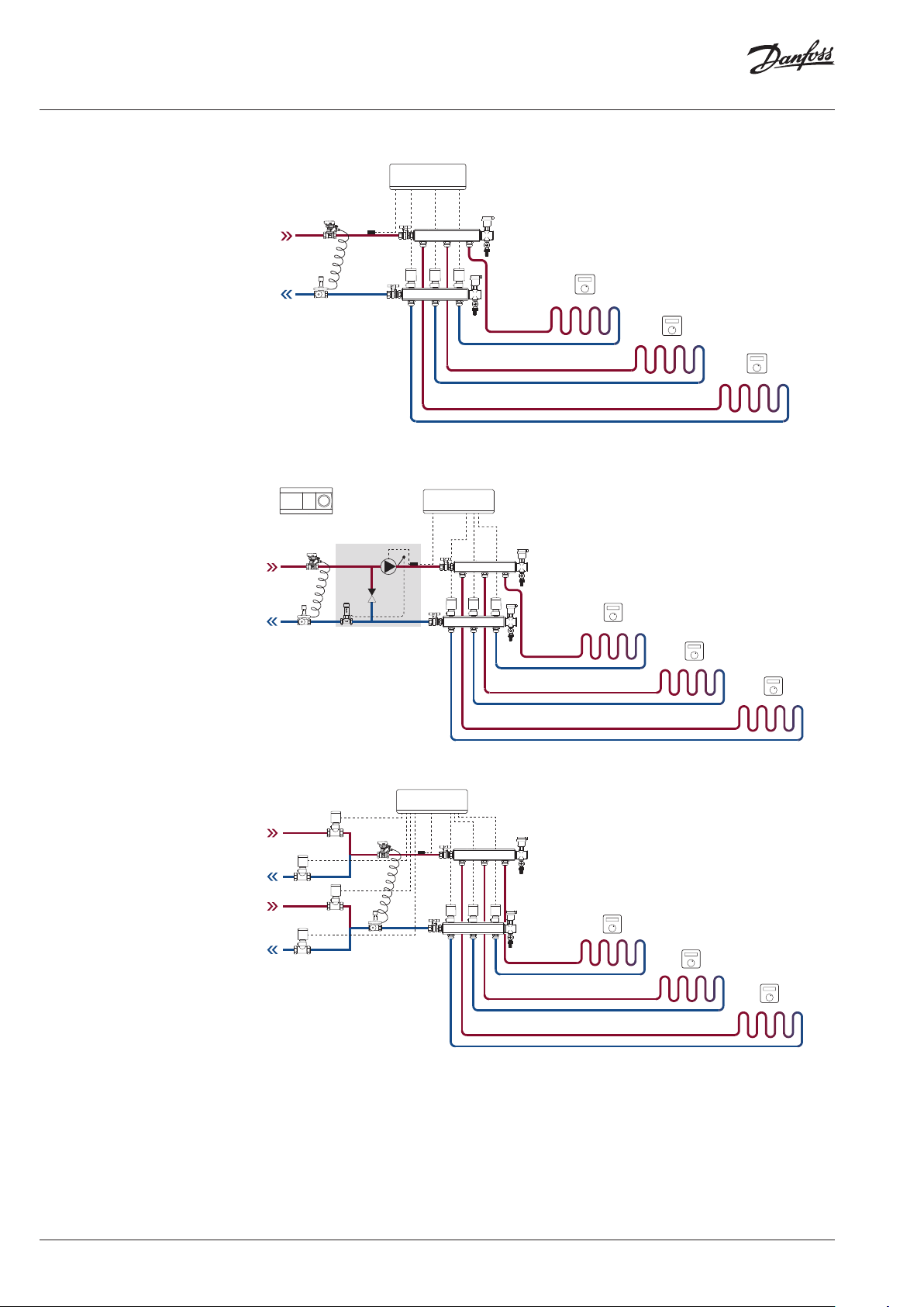
Application drawings
Example 1: 2-pipe system (optional cooling)
Example 2: 2-pipe system with mixing shunt
(optional supply temperature control)
23
Example 3: 4-pipe cooling
2 | © Danfoss | FEC | 2020.03
AI289334683789en-000102 / VDMCB102
Page 3

Data Sheet Danfoss Icon™ 24V Master Controller
Technical data
Common characteristics,
all Danfoss Icon™ products
Master Controller 24V and
Expansion Module (optional)
For all applications please see Installation guide for Expansion Module.
Temperature for the ball pressure test 75 °C
Control polution degree Degree 2, normal household environment
Software class Class A
Rated impulse voltage 4 kV
Operating time Permanently connected
Temperature range, storage and transportation -20 °C to +65 °C
Dispossal instructions The product must be disposed as electronic waste
Supply voltage 220-240 V AC
Supply frequency 50/60 Hz
Output voltage, actuators 24 V DC
Max. power consumption per actuator output 2 W
Number of actuator outputs
10 or 15 depending on type of Master Controller
(1 actuator per output terminal)
Output voltage, thermostats 24 V DC
Stand-by consumption per thermostat 0,2 W
Max. number of thermostats 10 or 15 depending on type of Master Controller
Max. length of wire from master controller to a
24 V thermostat (depends on cable type used)
If 2 × 2 × 0,6 mm² STP/UTP: 100 m
If 2 × 0,5 mm²: 150 m
If > 2 × 0,75 mm²: 200 m
Stand-by consumption, Master Controller < 2 W
Max. power consumption, excluding use of
< 50 W
PWR 1 and PWR 2 outputs
Internal protection (fuse, non-replacable) 2,5 A
Output “Relay” Potential free relay, Max. 2 A load
Actuator outputs, type Type 1C (Micro interuption)
Output “PWR 1”, type and rated max. output Type 1B (Micro disconnection)
Output “PWR 2”, type and rated max. output Type: Permanent output, 230 V, max. 50 W
Output “PWR 3” (optional, on Expansion
24 V DC, max. 1 W
Module - used for dew point sensor)
Input “1” (optional, on Expansion Module - use
Ext. switch input (internal 24 V pull-up)
varies acc. to application chosen)
Input “2” (optional, on Expansion Module - use
Ext. switch input (internal 24 V pull-up)
varies acc. to application chosen)
Input “3”, sensor input (optional, on Expansion
External sensor, PT 1000 (Danfoss ESM 11)
Module)
Dimensions W: 370 mm, H: 100 mm, D: 53 mm
Conformity declared acc. to following directives LVD, EMC, RoHS and WEEE
Purpose of control Individual electronic room temperature control
Method of providing earthing Factory fitted power cord, incl. PE-conductor
Encapsulation (IP Class) IP 20
Protection class Class II Construction with earthing terminal
Ambient temperature range, continious use 0 °C to 50 °C
© Danfoss | FEC | 2020.03
AI289334683789en-000102 / VDMCB102 | 3
Page 4

Danfos
produc
Al
Danfoss A/S
Heating Segment • heating
101
50
54
Technical data
Radio Module & Repeater
Purpose of control Transmitting and receiving device
Ambient temperature range, continious use 0 °C to 40 °C
Frequency 868,4–869,85 MHz
Transmission power < 2,5 mW
Encapsulation (IP Class) IP 20
Conformity declared acc. to following directives RED, RoHS, WEEE
Protection class Radio: Class III Construction;
Repeater: Class II Construction
Supply voltage Radio: 5 V DC; Repeater: 230 V AC 50/60 Hz
App Module
Drawings
Purpose of control Wi-Fi transmitting and receiving device,
incl. Bluetooth
Ambient temperature range, continious use 0 °C to 40 °C
Frequency 2,4 GHz
Encapsulation (IP Class) IP 20
Conformity declared acc. to following directives RED, RoHS, WEEE
Protection class Radio: Class III
Supply voltage 5 V DC
372
1 2 3 987654 10
50
10
354 8
Danfoss Icon™ 24V Master Controller
s can accept no responsibility for possible errors in catalogues, brochures and o ther printed material. Danfoss reserves the right to alter its products w ithout notice. This also applies to
ts already on order provided that such alterations can be m ade without subsequential changes being necessary in specications already agreed.
l trademarks in this material are p roperty of the r espective companies. Danfoss and a ll Danfoss logotypes are trademarks of Danfoss A/S. All rights r eserved.
4 | © Danfoss | FEC | 2020.03
97
53 24
Danfoss Icon™ Expansion Module Danfoss Icon™ Radio Module
.danfoss.com • +45 7488 2222 • E-Mail: heating@danfoss.com
125
29 69
AI289334683789en-000102 / VDMCB102
 Loading...