

Page 1
Optyma™ iCO2
Condensing Units OP-MPAM005COP04G
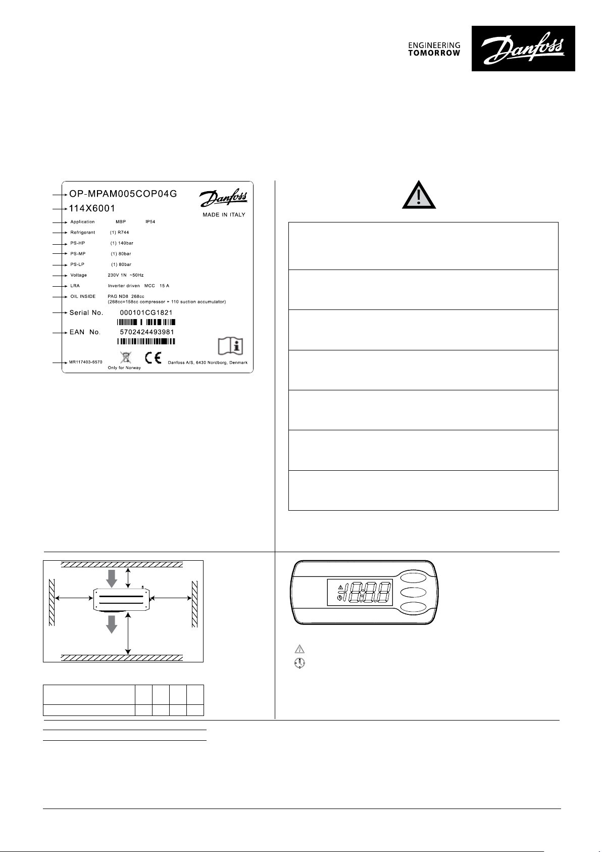
Name plate
A
B
C
D
E
F
G
H
I
J
K
L
This unit contains frequency converter and EMI filter with capacitors. Disconnect the AC mains and wait for at least 4 min to de-Energize all Electrical parts
before opening the door for performing any service or repair work. Failure to
wait the specified time after power has been removed could result in death
or serious injury
Installation and servicing of the condensing units by qualified personnel
only. Follow these instructions and sound refrigeration engineering practice
relating to installation, commissioning, maintenance, and service.
The condensing unit must only be used for its designed purpose(s) and within
its scope of application.
M
* For exact values please refer name plate in unit
A: Model
B: Code number
C: Application, IP protection level
D: Refrigerant (R744=CO2)
E: Maximum working pressure
F: Middle working pressure
G: Minimum working pressure
H: Supply voltage
I: Locked Rotor Ampere, Maximum Current Consumption
J: Oil type
K: CDU serial number
L: European Article Number
M: Condensing unit Label PN (Factory)
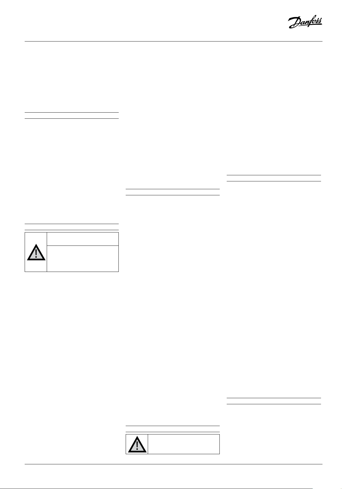
Q
W
ZY
R
X
Picture 1 : Minimum mounting distances
Q: Air in R: Air out
Unit
Housing 250 760 581 581
W
[mm]X [mm]Y [mm]Z [mm]
Under all circumstances, the EN378 (or other applicable local safety regulation) requirements must be fulfilled.
The condensing unit is delivered under nitrogen gas pressure (1 bar) and
hence it cannot be connected as it is; refer to the «installation» section for
further details.
The condensing unit must be handled with caution in the vertical position
(maximum offset from the vertical: 15°)
Compressor of condensing unit cannot be connected directly to the network
in any case, only via original drive from Danfoss.
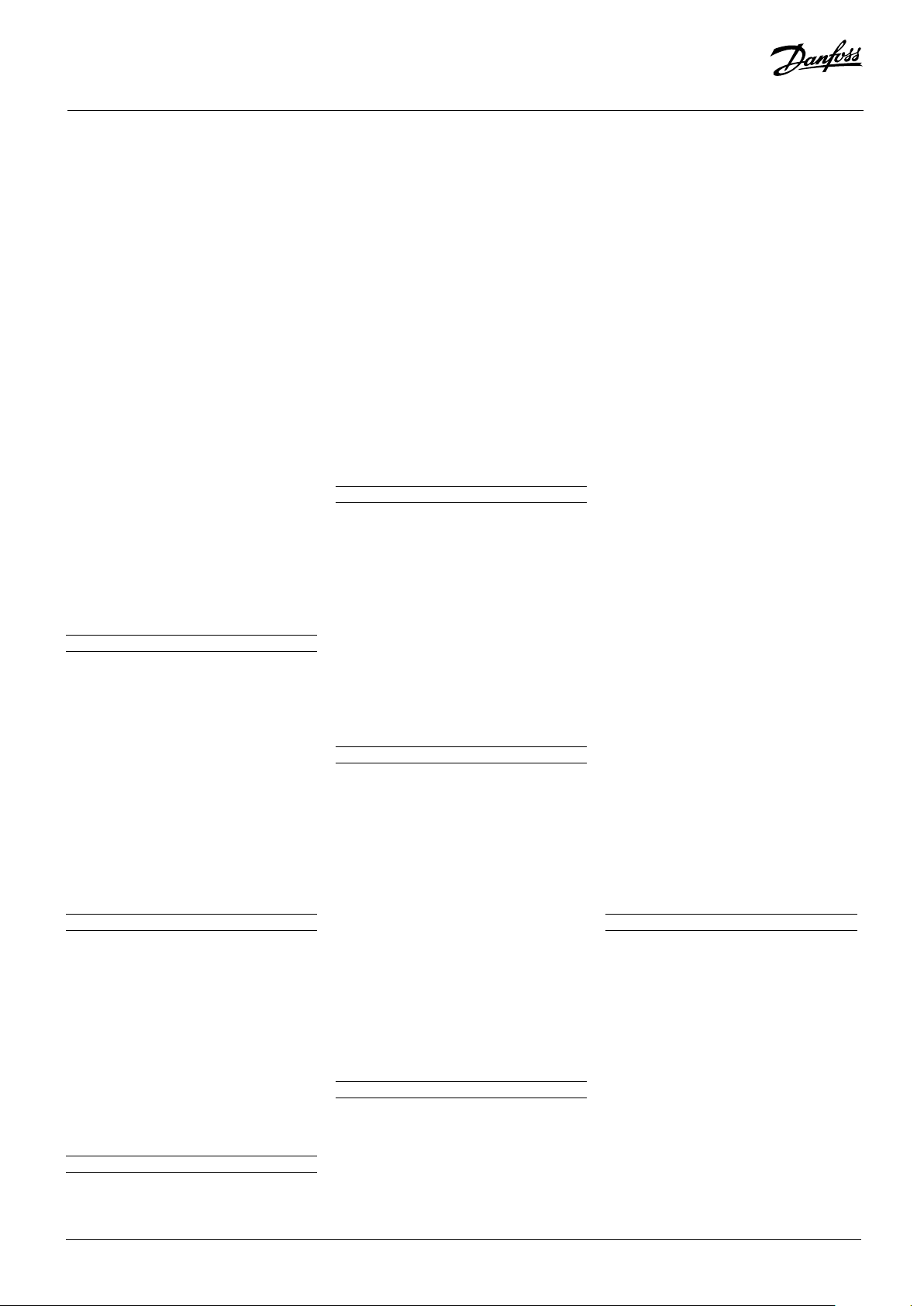
Picture 3 : Electronic controller display
Active alarm
No function
Display shows temperature value for suction
pressure. Push middle button to switch to
Evaporating temp. setpoint.
1- Introduction
These instructions pertain to Optyma™ iCO
condensing units OP-MPAM005COP04G
used for refrigeration systems. They provide
necessary information regarding safety and
proper usage of this product.
© Danfoss | Climate Solutions | 2021.12
The condensing unit includes following:
• Microchannel heat exchanger
• Variable speed scroll compressor
• Receiver
• Pressure relief valve
• Suction accumulator
• Oil separator integrated to the compressor
• Ball valves with Shrader for unit inlet and
outlet
• Sight glass on liquid line
• Filter drier
AN399635986435en-000101 | 1
Page 2
Instructions
• High pressure switch
• Electronic controller
• high and medium pressure valves
• Compressor drive with EMC filter
• Main circuit breaker (Main switch with
overload protection)
• DC Fan
• Robust weatherproof housing
2 - Handling and storage
• It is recommended not to open the
packaging before the unit is at the final
place for installation.
• Handle the unit with care. The packaging
allows for the use of a forklift or pallet
jack. Use appropriate and safe lifting
equipment.
• Store and transport the unit in an upright
position.
• Store the unit between -35°C and 50°C.
• Don’t expose the packaging to rain or
corrosive atmosphere.
• After unpacking, check that the unit is
complete and undamaged.
3 - Installation precautions
Never place the unit in a
flammable atmosphere.
Place the unit in such a way that
it is not blocking or hindering
walking areas, doors, windows
or similar.
• Ensure adequate space around the unit for
air circulation and to open doors. Refer to
picture 1 for minimal values of distance to
walls.
• Avoid installing the unit in locations which
are daily exposed to direct sunshine for
longer periods.
• Avoid installing the unit in aggressive and
dusty environments.
• Ensure a foundation with horizontal
surface (less than 3° slope), strong and
stable enough to carry the entire unit
weight and to eliminate vibrations and
interference.
• The unit ambient temperature may not
exceed 46°C during off-cycle.
• Ensure that the power supply corresponds
to the unit characteristics (see nameplate).
• Use clean and dehydrated refrigerationgrade copper tubes.
• Use clean and dehydrated system
components.
• The suction piping connected to the
compressor must be flexible in 3
dimensions to dampen vibrations.
Furthermore, piping must be done in such
a way that oil return for the compressor is
ensured and the risk of liquid slug over in
compressor is eliminated.
• Evaporator, suction, and liquid line must
be rated for PS 80 barg.
• Liquid line and receiver are protected by
a pressure relieve valve connected to the
receiver. Pressure limit set at 80 barg.
• Suction line must be protected by a
pressure relief valve set at 80 barg.
• All section of system that can be close by
isolation valve must be protected by a
PRV or a check valve to allow flow in the
direction of a PRV.
• Pressure relieve valve must be place where
no risk for people or goods
• Piping must be supported and clamped.
• The machine room if any and cold room
must be equipped with a CO detector
according to EN378.
4 - Installation
• The installation in which the condensing
unit is installed must comply to European
community Pressure directive (PED) and
European standard EN 378.
• The condensing unit itself is a partly
completed machine, which is not in the
scope the PED directive.
• It is recommended to install the unit on
rubber grommets or vibration dampers
(not supplied).
• Slowly release the nitrogen holding charge
through the Shrader port.
• Connect the unit to the system as soon as
possible to avoid oil contamination from
ambient moisture.
• Avoid material entering the system while
cutting tubes. Never drill holes where
burrs cannot be removed.
• Braze with great care using state-ofthe-art technique and vent piping with
nitrogen gas flow.
• Connect the required safety and control
devices.
• Liquid line and return line must be
thermally insulated. A badly insulated
liquid line can generate flash gas during
operation and receiver over pressure
during standstill. Receiver overpressure
can eventually result in the release of
refrigerant through the receiver PRV.
• Apply liquid and return line insulation
after leak test .
5 - Leak and pressure test
Never pressurize the circuit
with oxygen or dry air. This
could cause fire or explosion.
Do not use dye for leak detection.
• Pressure tests:
- Close condensing unit shutoff valve.
We don’t want receiver relief valve to
discharge during pressure test.
- make sure evaporator expansion valve
is open.
- pressure test liquid and return line at 1,1
x PS = 88 bar with nitrogen.
• Leak test:
- Perform a leak detection test on the
complete system at pressure P = 0,25 x
PS = 20 bar.
- When a leak is discovered, repair the
leak, and repeat the leak detection.
• After completion of test, vent nitrogen to
atmosphere and open condensing unit
service valve.
6 - Electrical connections
• Switch off and isolate the main power
supply.
• Ensure that power supply cannot be
switched on during electrical connection.
• All electrical components must be
selected as per local standards and unit
requirements.
• Refer to wiring diagram for electrical
connections details.
• Ensure that the power supply corresponds
to the unit characteristics and that the
it is stable (nominal voltage ±10% and
nominal frequency ±2,5 Hz).
• Dimension the power supply cables
according to unit data for voltage and
current, ambient temperature and cable
grouping.
• Protect the power supply against overload,
mechanical stress, and damage, and
ensure correct earthing.
• Make the power supply according to local
standards and legal requirements.
• The unit is equipped with an electronic
controller.
• The unit is equipped with a main switch
with overload protection.
• The unit is equipped with high pressure
switch, which directly cut the power
supply to the compressor in case of
activation. PS = 140 bar.
7 - Setting the electronic controller
• The unit is equipped with an electronic
controller which is factory programmed
with parameters for use with the actual
unit. Refer to application guideline for
details.
• Energize the unit.
• The electronic controller display shows
the temperature value for the suction
© Danfoss | Climate Solutions | 2021.122 | AN399635986435en-000101
Page 3
Instructions
pressure.
• A short push on middle button show
evaporating temperature setpoint r23.
Factory setting of r23 = -10°C.
• Controller main switch parameter r12
should be set to 0 = stop (factory setting ).
• To change controller parameter,
- Push the upper button for a couple of
seconds. The first parameter code r05
appears.
- Push the upper or lower button to find
parameter.
- Push the middle button until the value
for this parameter is shown.
- Push the upper or lower button to
select the new value.
- Push the middle button to confirm the
selected value.
- Select next parameter with upper or
lower button or simply wait 20s to
return to main display.
• If necessary, change parameter r23 to
desired suction pressure (°C/°F).
• Change parameter c75 for pump down
(OFF) and c76 for restart (ON) value
according to your needs.
8 - Vacuum dehydration
• Before vacuuming the system, you need to
open fully high pressure and bypass valve.
Unit must be connected to power supply
and controller main switch r12 must be
set to value 2 = Vacuum mode.
• Connect a vacuum pump to both the LP &
HP sides.
• Pull down the system under a vacuum of
500 µm Hg (0.67 mbar) absolute.
• Do not use a megohmmeter nor apply
power to the compressor while it is
under vacuum as this may cause internal
damage.
9 - Oil addition
• Make calculation of oil charge addition
with the excel sheet “Danfoss calculation
of additional oil charge”
• If additional oil needed, you have
additional oil can inside the unit charge
through the suction service valve.
• If further oil is require you can get it from
Danfoss article code : 118U4144 (250ml)
• The condensing unit is supply with
Idemitsu PAG ND8 oil. Be sure to use same
oil type
10 - Filling the system
• Use only R744 refrigerant grade 4.5
(99,995%).
• Make calculation of refrigerant charge
with the excel sheet before charging.
• Use a scale to measure the refrigerant
charge you put in the system.
• Condensing unit main switch r12 must be
set to value 2 = Vacuum mode.
• Start fill the refrigerant in vapor phase into
the liquid line. Ensure a slow charging of
the system to 7-10 bar. This charging in
vapor phase is required to avoid dry ice
formation inside the circuit. Dry ice could
prevent the charging of the circuit.
• When pressure in circuit reach 7-10 bar, fill
the refrigerant in liquid phase into liquid
line till you reach the charge given by the
excel sheet.
• You may need to finish the charge in
vapor phase on suction line when unit is
running.
11 - Start-up
• All service valves must be in the open
position.
• Check that the fan can rotate freely.
• After filling the system, condensing unit
main switch r12 is set to 2 = Vacuum
mode. To start the unit, first set r12 to
value 0 = Stop. And then set r12 to value
1 = Automatic. Unit will make a reset of
motorized valve and start.
• If the compressor does not start, check
wiring conformity and voltage on
terminals.
12 - Check with running unit
• Check the fan rotation direction. Air must
flow from the condenser towards the fan.
• Check current draw and voltage.
• Check suction superheat to reduce risk of
slugging. The optimum unit return gas
superheat is around 6K. The maximum
allowed superheat is 30K.
• Respect the operating limits.
• Check all tubes for abnormal vibration.
Movements more than 1.5 mm require
corrective measures such as tube brackets
or balance weight.
• For charge adjustment please refer to next
section
• in case of problem see Trouble shooting
section
13 - Charge adjustment
• The remaining charge is done when
installation has reached stable condition
during operation.
• Do not overcharge the system.
• Overfilling the system may risk in pressure
increase and release of refrigerant through
the receiver relief valve.
• Liquid line sight glass should be 3/4 filled
with liquid. A sight glass with 100% liquid
could be an indication of overcharge.
• Tuning of refrigerant charge should
be done by looking at the evaporator
superheat, evaporator expansion valve
opening and suction pressure value.
• Low charge will give low evaporating
pressure, high superheat, largely open
evaporator expansion valve
• Correction for overcharged unit: Release
refrigerant via the access port of the
suction side. Connect a service pipe
equipped with a shutoff valve to the
Shrader port. Open the valve very slowly.
• Correction in case of refrigerant shortage:
Charge additional refrigerant through the
low pressure Shrader port in vapor phase.
Open the cylinder valve very slowly.
• Do not fill with liquid on suction line. It
risks damaging the compressor.
• Do not fill on liquid line when system
is running. Depending on running
conditions, pressure of liquid line can
reach high values. higher than cylinder
pressure.
• Simulate high ambient by covering the
gascooler and check system run correctly.
• Make a pump down to control the correct
charge: with too low charge, system may
have difficulty to recover after a pump
down.
• Never leave the filling cylinder connected
to the circuit.
• Record type and amount of refrigerant
charge as well as operating conditions as
a reference for future inspections.
• Before leaving the installation site, carry
out a general installation inspection
regarding cleanliness, noise, and leak
detection.
14 - Trouble shooting
• Compressor failure to build up pressure:
Check all bypass valves in the system
to ensure that none of these has been
opened. Also check that all solenoid
valves are in their proper position.
• Abnormal running noise: Ensure the
absence of any liquid flood-back to the
compressor by means of measuring the
return gas. Superheat should be at least 6K
above the saturated suction temperature
under steady-state operating conditions.
• The high-pressure switch trips: Check
condenser operation (condenser
cleanliness, fan operation). If all these are
OK, the problem may be due to either
refrigerant overcharging or the presence
AN399635986435en-000101 | 3© Danfoss | Climate Solutions | 2021.12
Page 4

Instructions
of a non-condensable (e.g. air, moisture)
in the circuit.
• The low-pressure switch trips: Check
evaporator operation (coil cleanliness,
fan operation, defrost, water flow, water
filter, etc.), liquid refrigerant flow and
pressure drops (solenoid valve, filter dryer,
expansion valve, etc.), refrigerant charge.
15 - Maintenance
Always switch off the unit at main
switch and wait 4 minutes (capacitor
discharge time) before opening the
fan door to avoid electric shock.
Even when main switch is OFF,
voltage is available on the income
terminals of main switch and
this should be considered during
maintenance and service repair.
Internal pressure and surface
temperature are dangerous and
may cause permanent injury.
Maintenance operators and
installers require appropriate skills
and tools. Tubing temperature may
exceed 100°C and can cause severe
burns.
Ensure that periodic service
inspections to ensure system
reliability and as required by local
regulations are performed.
Before working on pressurized component,
shut down the unit and wait until
equipment is at the ambient temperature.
To prevent system related problems,
following periodic maintenance is
recommended:
• Verify that safety devices are operational
and properly set.
• Ensure that the system is leak tight.
• Check the compressor current draw.
• Confirm that the system is operating in a
way consistent with previous maintenance
records and ambient conditions.
• Check that all electrical connections are
still adequately fastened.
• Keep the unit clean and verify the
absence of rust and oxidation on the
unit components, tubes, and electrical
connections.
• The condenser must be checked at least
once a year for clogging and be cleaned if
deemed necessary. Access to the internal
side of the condenser takes place through
the fan door. Microchannel coils tend
to accumulate dirt on the outer surface
rather than inside, which makes them
easier to clean than fin-&-tube coils.
• Switch off the unit at main switch before
opening the fan door.
• Remove surface dirt, leaves, fibers,
etc. with a vacuum cleaner, equipped
with a brush or other soft attachment.
Alternatively, blow compressed air
through the coil from the inside out, and
brush with a soft bristle. Do not use a wire
brush. Do not impact or scratch the coil
with vacuum cleaner tube or air nozzle.
• If the refrigerant system has been opened,
the system must be flushed with dry air or
nitrogen to remove moisture and a new
filter drier must be installed.
16 - Empty the system
• Set controller main switch r12 to value 2 =
vacuum mode. This will stop compressor
and force bypass valve and high-pressure
valve fully open.
• Connect a service pipe equipped with a
shutoff valve to suction line Shrader port.
• Open the valve slowly and discharge
refrigerant in free atmosphere
• Ensure proper ventilation of location
where refrigerant is release.
• Do no discharge refrigerant from liquid
line. You will risk dry ice formation inside
the pipe. Ice could prevent the flow of
refrigerant and generate a sudden burst
of CO when it melts.
17 - Warranty
• Always transmit the model number
and serial number with any claim filed
regarding this product.
• The product warranty may be void in
following cases:
• Absence of nameplate.
• External modifications, in particular
drilling, welding, broken feet, and shock
marks.
• Compressor opened or returned unsealed.
• Rust, water, or leak detection dye inside
the compressor.
• Use of a refrigerant or lubricant not
approved by Danfoss.
• Any deviation from recommended
instructions pertaining to installation,
application, or maintenance.
• Use in mobile applications.
• Use in explosive atmospheric environment.
• No model number or serial number
transmitted.
18 - Disposal
Danfoss recommends that
condensing units and oil should be
recycled by a suitable company at
its site.
© Danfoss | Climate Solutions | 2021.124 | AN399635986435en-000101
Page 5

Instructions
GA & PID Drawings
OP-MPAM005COP04G
1379.3
C
550.5
A
English Legend
A Ø12 Hole for Mounting
B Sight Glass
C Controller Display
842.8
1252.2
D Air in
E Air out
F Suction Port
B
353
E
H
D
F
G
G Liquid Port
H Nameplate
Electrical Cables
Note: all dimension are in mm
AN399635986435en-000101 | 5© Danfoss | Climate Solutions | 2021.12
Page 6

Instructions
PID (Piping & Instrumentation Diagram)
© Danfoss | Climate Solutions | 2021.126 | AN399635986435en-000101
Page 7

Instructions
Φ
Φ
Φ
Φ
ΦΦΦ
Φ
Φ
Φ
Φ
Φ
Φ
Φ
Φ
Φ
Wiring Diagram
OP-MPAM005COP04G
WD 1
AN399635986435en-000101 | 7© Danfoss | Climate Solutions | 2021.12
Page 8

8 | AN399635986435en-000101
© Danfoss | Climate Solutions | 2021.12
 Loading...